Download Device description
Transcript
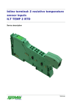
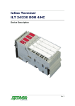
Inline Terminal: ILT AI/TEMP4 RTD Device Description Preliminary Disclaimer / Imprint This manual is intended to provide support for installation and usage of the device. The information is believed to be accurate and reliable. However, SysMik GmbH Dresden assumes no responsibility for possible mistakes and deviations in the technical specifications. SysMik GmbH Dresden reserves the right to make modifications in the interest of technical progress to improve our modules and software or to correct mistakes. We are grateful to you for criticism and suggestions. Further information (device description, available software) can be found on our homepage www.sysmik.de. Please ask for latest information. SysMik disclaims all warranties in case of improper use or disassembly and software modifications not described in this document or when using improper or faulty tools. Commissioning and operation of the device by qualified personnel only. All applicable regulations have to be observed. SysMik® and the SysMik logo are registered trademarks of SysMik GmbH Dresden. IPOCS™ is © trademark of SysMik GmbH Dresden. "Networking Together!" is subject to copyright of SysMik GmbH Dresden. All other trademarks mentioned in this document are registered properties of their owners. These and further trademarks are used in this document but not marked for better readability. No part of this document may be reproduced or modified in any form without prior written agreement with SysMik GmbH Dresden. Copyright © 2014 by SysMik GmbH Dresden SysMik GmbH Dresden Tel + 49 (0) 351 – 4 33 58 – _0 Bertolt-Brecht-Allee 24 Fax + 49 (0) 351 – 4 33 58 – 29 01309 Dresden E-Mail (Sales) E-Mail (Support) Germany 2 Homepage sysmik.de [email protected] [email protected] www.sysmik.de ILT AI/TEMP 4 RTD Contents Contents Device Description 1 Contents 3 1 Overview 4 2 Order Information 4 3 Connections 5 3.1 Wiring Example 7 3.2 Installation Instructions 7 4 Selecting Measuring Mode and Sensors 8 1.1 Systematic Errors 8 1.2 Tolerance and Drift 8 5 Technical Data 11 6 Literature 12 ILT AI/TEMP 4 RTD sysmik.de 3 Overview / Order informationi 1 Overview The terminal IB IL AI/TEMP 4 RTD-PAC is designed for use within an Phoenix Contact Inline station. It provides 4 analog input channels, which can be configured independently from each other either as voltage or resistance and/or resistive temperature detector (RTD) inputs. The sensor interface uses 2-wire technology, hence a nominal sensor resistance of at least 1000 Ω is being advised in case of sensors with comparatively small temperature coefficient (e.g. platinum sensors). For temperature measurement with NTC sensors, whose big advantage is a large temperature coefficient, use resistance measurement with temperature calculation by means of characteristics interpolation performed by the bus controller. The terminal with its 4 channels and a width of 12.2 mm is very compact built. Features: 4 analoge inputs, configurable as 0-10 V voltage inputs resistor inputs from 10 Ω up to 300 kΩ, values either as Ohm or percent Platinum sensors according to DIN EN 60751 and/or IEC 751 and SAMA Nickel sensors according to DIN 43760 and SAMA KTY81-110, KTY81-210, KTY84 Viessmann Ni500, Viessmann NTC10 k Siemens LG-Ni1000 Temperature output as Celsius [°C] or Fahrenheit [°F] width only 12.2 mm (0.48 inch) 2-wire technology Note: This data sheet is only valid in association with the IL SYS INST UM E user manual of Phoenix Contact (see [1]) or the Inline system manual for your bus system. 2 Order Information Device Part number IL AI/TEMP 4 RTD 1225-100275-07-6 Table 2.1: Order information 4 sysmik.de ILT AI/TEMP 4 RTD Connections 3 Connections D AI/TEMP 4 RTD 1.1 2.1 1.2 2.2 1.3 2.3 1.4 2.4 1.5 2.5 1.6 2.6 Fig. 3.1: Terminal connections Indicator Color Description D green bus diagnostics Table 3.1: Local diagnostic and status indicator Terminal point Signal Assignment 1.1 sensor (both resistance and voltage) input channel 1 1.2 +AI1 1) sensor ground channel 1 1) shield channel 1 AGND 1.3 Shield 1.4 +AI3 1.5 sensor (both resistance and voltage) input channel 3 1) sensor ground channel 3 1) shield channel 3 AGND 1.6 Shield 2.1 +AI2 2.2 sensor (both resistance and voltage) input channel 2 1) sensor ground channel 2 1) shield channel 2 AGND 2.3 Shield 2.4 +AI4 2.5 2.6 1) sensor (both resistance and voltage) input channel 4 1) sensor ground channel 4 1) shield channel 4 AGND Shield Connectors AGND and Shield are internally connected to each other Table 3.2: Terminal assignment ILT AI/TEMP 4 RTD sysmik.de 5 Connections OPC Local Bus OPC Protocol chip µC UL+ UANA UL- Microcontroller with Multiplexer andAnalog-Digital-Converter MUX UL DC-DC-Converter with galvanically isolation 3.3V UL Coupling network 3.3V µC MUX Analog ground EEPROM REF Optocoupler REF Voltage reference EEPROM +24V US Non-volatile memory +24V UM Fig. 3.2: Functional overview (without plug) 6 sysmik.de ILT AI/TEMP 4 RTD Connections 3.1 Wiring Example D D AI/TEMP 4 RTD AI/TEMP 4 RTD 1.1 2.1 1.1 2.1 +AI 2 +AI1 OUT1 1.3 2.3 1.4 2.4 +AI4 OUT3 OUT4 1.5 2.5 AGND AGND AGND 1.6 2.6 1.6 2.6 Shield +AI4 +AI3 1.5 2.5 AGND Shield Shield Shield 1.4 2.4 +AI3 AGND AGND AGND 1.3 2.3 Shield OUT2 1.2 2.2 1.2 2.2 AGND +AI 2 +AI1 Shield Shield Shield Fig 3.1.1: Wiring example of resistive sensors (left) and voltage measurement (right) Note: Always connect sensors using twisted pair cabling. Note: Shielding may reduce the influence of electromagnetic interferences. Connect the shield with the shield connector of the terminal and isolate it at the sensor. Note: Short-circuit unused channels to sensor ground. 3.2 Installation Instructions Currents flowing through the potential jumpers UM and US cause a temperature rise inside the terminal. Note the following instruction to minimize this influence: Instruction: Create a separate main circuit for the analog terminals or place the analog circuits after all other terminals at the end of a main circuit! ILT AI/TEMP 4 RTD sysmik.de 7 Selecting Measuring Mode and Sensors 4 1.1 Selecting Measuring Mode and Sensors Systematic Errors When measuring resistance and temperature by means of resistive temperature sensors, systematic errors may cause significant errors. With 2-wire technology, the biggest systematic error is caused by the resistance of the sensor cable and the contact resistances. The measuring error is proportional to the relation between resistance of sensor cables and contacts and coefficient of the sensor. This error cannot completely be compensated by calibration, because it is depending from the temperature of the cable. The temperature coefficient of Pt100 sensors is approximately 0.385 Ω/K. The resistance of a 10 m sensor cable with a cross section of 0.5 mm² is about 0.712 Ω and distorts the measuring result by nearly 2 K. The temperature depending change of the cable resistance and the contact resistance have to be additionally considered. The temperature coefficient of Pt1000 is 10 times higher in comparison to Pt100. According to that, the influence of cable and contact resistance is 10 times smaller. There are resistive temperature sensors with even higher temperature coefficients, e.g. NTC sensors. Note: Chose temperature sensors with temperature coefficients as high as possible in order to minimize the influence of systematic errors. We recommend sensors of appropriate type (preferable NTC) and/or with a nominal resistance of at least 1000 Ω (with Ni or Pt). 1.2 Tolerance and Drift The influence of measuring errors, which are caused by tolerance and drift of the measuring device, can be reduced by proper choice of measuring mode and sensor type. Basically, the same recommendations as with systematic errors have to be considered. Table 5.2.1 shows an overview of tolerance and drift of the several measuring modes. Table 5.2.2 contains an overview of the temperature coefficients of selected sensor types. With this information, it can be estimated, which errors can be caused by a certain combination of measuring mode and sensor type. Note: Regard 3.2 in order to reduce temperature rise of the terminal within the Inline station and the resulting temperature drift of the terminal. 8 sysmik.de ILT AI/TEMP 4 RTD Selecting Measuring Mode andSensors Measuring mode Typical 1) Range Tolerance Relative2) Absolute Maximal Absolute Relativ2) TU = 25 °C (77 °F) 0-10 V 0-10 V ±20 mV ±0.2 % ±50 mV ±0.5 % 0-3 kΩ 0-2.2 kΩ 3) ±1 Ω ±0.1 % ±3.0 Ω ±0.2 % 0-500 kΩ 0-5 kΩ 5-20 kΩ 20-100 kΩ 20-300 kΩ ±5 Ω ±20 Ω ±300 Ω ±2500 Ω ±0.1 % ±0.1 % ±0.3 % ±0.8 % ±10 Ω ±40 Ω ±600 Ω ±5000 Ω ±0.2 % ±0.2 % ±0.6 % ±1.7 % TU range of -25 °C to +55 °C (-13 °F to 131 °F) 0-10 V 0-3 kΩ 0-300 kΩ 0-10 V ±50 mV ±0.5 % ±150 mV ±1.5 % 3) ±2 Ω ±0.1 % ±8 Ω ±0.4 % 0-5 kΩ 5-20 kΩ 20-100 kΩ 100-300 kΩ ±10 Ω ±80 Ω ±1500 Ω ±12000 Ω ±0.2 % ±0.4 % ±1.5 % ±4.0 % ±20 Ω ±160 Ω ±3000 Ω ±24000 Ω ±0.4 % ±0.8 % ±3.0 % ±8.0 % 0-2.2 kΩ 1) A measuring mode can comprise multiple virtual ranges, each of which has to be considered separately, because the accuracy of measuring mode varies over its full range. 2) Relative specifications are related to the upper limit of the respective range. 3) Tolerance specifications only valid up to 2.2 kΩ Table 4.1: Tolerance of measuring modes ILT AI/TEMP 4 RTD sysmik.de 9 Selecting Measuring Mode and Sensors Sensor type Temperature range from Resistance range to from to Temperature coeffizient at 25 °C (77 °F) NTC10 k, B=3988 0 °C 70 °C 32650.0 Ω 1752.0 Ω -461.00 NTC20 k, B=4300 0 °C 70 °C 71126.0 Ω 3061.0 Ω -996.00 Pt1000 DIN -100 °C 850 °C 603.4 Ω 3904.8 Ω 3.88 Pt1000 SAMA -200 °C 600 °C 166.6 Ω 3118.7 Ω 3.88 Ni1000 DIN -60 °C 180 °C 695.2 Ω 2232.2 Ω 5.81 Ni1000 SAMA Type I -40 °C 200 °C 779.0 Ω 2490.2 Ω 6.11 KTY81-110 -55 °C 150 °C 490.0 Ω 2211.0 Ω 7.80 KTY81-210 -55 °C 150 °C 980.0 Ω 4280.0 Ω 15.60 KTY84 -40 °C 300 °C 359.0 Ω 2624.0 Ω 4.40 Siemens LG Ni 1000 -30 °C 160 °C 871.7 Ω 1863.6 Ω 4.70 Viessmann Ni 500 -40 °C 40 °C 412.0 Ω 576.0 Ω 2.40 10 °C 110 °C 20000.0 Ω 400.0 Ω -625.00 Viessmann NTC 10 k Table 4.2: Selected sensor parameters 10 sysmik.de ILT AI/TEMP 4 RTD Technical Data 5 Technical Data General data without connectors Dimensions (width x height x depth) with connectors 12.2 mm x 120 mm x 71.5 mm 12.2 mm x 142 mm x 71.5 mm without connectors 46 g with connectors 68 g Weight Operating mode Permissible temperature process data operation with 2 words operation -25 °C to +55 °C (-13 °F to +131 °F) storage / transport -25 °C to +85 °C (-13 °F to +185 °F) Permissible humidity 75 % on (non condensing) average, 85 % occasionally operation 80 kPa to (up to 2000 m / 6562 ft. above sea level) 106 kPa storage / transport 70 kPa to (up to 3000 m / 9843 ft. above sea level) 106 kPa Permissible air pressure Degree of protection IP20 according to IEC 60529 Interfaces Local bus Connection through data routing Transmission speed 500 kBaud Power consumption Communications power UL 7.5 V DC Current consumption at UL ≤ 60 mA (typical) Total power consumption ≤ 0.45 W (typical) ILT AI/TEMP 4 RTD sysmik.de 11 Technical data / Literature Analog inputs Number 4 Signal connection 2-wire, shielded Sensor types Pt, Ni, KTY, voltage 0-10 V Characteristic curves according to DIN, according to SAMA Conversion time of the A/D converter 150 ms Process data update of all 4 channels 600 ms Electrical isolation Electrical potentials The device is solely supplied by the logic circuit (logic voltage UL = 7.5 V). The analog inputs relate to a common electrical potential, which is galvanically isolated from all other circuits (UL, main circuit UM, segment circuit US, analog circuit UANA). Functional earth FE is a separate electrical potential and is connected to shield and analog ground via a coupling network, composed of an 1 MΩ resistor and a 1 nF capacitor in parallel. Isolated voltages Analog inputs ↔ UL / UM / US / UANA 500 V AC, 50 Hz, 1 min Table 5.1: Technical data 6 Literature [1] User manual IL SYS INST UM E: "Automation Terminals of the Inline Product Range", Phoenix Contact Phoenix Contact order no. 2698737 [2] www.phoenixcontact.com [3] www.sysmik.de 12 sysmik.de ILT AI/TEMP 4 RTD


