1
MiraiBio
®
DNASIS MAX
Version 2.5
Contig Manager
User's Manual
For Research Use Only
Part no. C-51125-10202
Preface
i
Preface
Thank you for purchasing DNASIS® MAX from MiraiBio. DNASIS® MAX incorporates an excellent,
user-friendly graphical user interface (GUI) and Contig Manager database for taking full control of fragments and
contigs. And by installing the Contig Manager Version 2.0, users can take advantage of sequence assembly at even
higher precision and higher-speed. Read this manual thoroughly to ensure correct usage.
Note:
●
The copyrights for this software and user manual belong to Hitachi Software Engineering Co., Ltd.
●
It is prohibited to copy or reproduce the contents of this manual in part or in whole.
●
This manual is subject to change without prior notice.
●
Hitachi Software Engineering Co., Ltd. is not responsible for any erroneous or incorrect descriptions in this
manual.
●
The use of this software and user manual is based upon agreement to the stipulations laid out in the Product
License Agreement.
First Edition July 2002 (invalid)
Second Edition February 2003 (invalid)
Third Edition April 2004
© 2002, 2004 Hitachi Software Engineering Co., Ltd. All rights reserved.
DNASIS is a registered trademark of Hitachi Software Engineering Co., Ltd.
DNASpace is a registered trademark of Hitachi Software Engineering Co., Ltd.
Windows is a registered trademark of Microsoft Corporation.
All other company and product names mentioned in this manual are trademarks or registered trademarks of their
owners.
Under the approval of UK Medical Research Council, TraceViewer program uses the io_lib library developed by
Staden Package of the UK.
Phred/Phrap is licensed from the University of Washington. The Phred/Phrap option for DNASIS is a product of
MiraiBio (USA).
ii
Contents
Preface......................................................................................................................... i
Phred/Phrap Option Installation and Default Settings .......................................... 1
Chapter 1 Contig Manager Tutorial ......................................................................... 7
1.1 Foreword ..................................................................................................................................9
1.1.1 Contig Manager ......................................................................................................................................................................9
1.1.2 Contigs and Fragments ...........................................................................................................................................................9
1.1.3 Data Management by Project .................................................................................................................................................9
1.1.4 Start up the Contig Manager ..................................................................................................................................................9
1.1.5 Create Projects........................................................................................................................................................................9
1.1.6 Part Names and Descriptions .................................................................................................................................................9
1.1.7 Close the Contig Manager ....................................................................................................................................................10
1.1.8 Data Used in the Tutorial .....................................................................................................................................................10
1.2 Analysis Example 1 - Assembling Trace Data ................................................................... 11
1.2.1 Start up the Contig Manager ................................................................................................................................................11
1.2.2 Create a Project ....................................................................................................................................................................11
1.2.3 Enter Trace Data ...................................................................................................................................................................12
1.2.4 Display Trace Data ...............................................................................................................................................................13
1.2.5 Trimming Parameter Setup 1................................................................................................................................................15
1.2.6 Add Vector Data....................................................................................................................................................................16
1.2.7 Trimming Parameter Setup 2................................................................................................................................................17
1.2.8 Perform Auto Assemble........................................................................................................................................................18
1.2.9 Display Contig Results.........................................................................................................................................................20
1.2.10 Sort and Display Trace Data ..............................................................................................................................................21
1.2.11 Reassembly .........................................................................................................................................................................22
1.2.12 Exit the Contig Manager ....................................................................................................................................................23
1.3 Analysis Example 2 - Sequence Clustering and DNASIS MAX Links ............................24
1.3.1 Start up the Contig Manager ................................................................................................................................................24
1.3.2 Create a Project ....................................................................................................................................................................24
1.3.3 Enter Trace Data ...................................................................................................................................................................25
1.3.4 Sequence Assembly ..............................................................................................................................................................26
1.3.5 Adjust the QV Threshold......................................................................................................................................................27
1.3.6 Examine Assembly Results ..................................................................................................................................................27
1.3.7 Display Assembly Status Details..........................................................................................................................................27
1.3.8 Link with DNASIS MAX.....................................................................................................................................................28
1.3.9 Manage Sequence Data by Folder........................................................................................................................................29
1.3.10 Create a New Folder...........................................................................................................................................................30
1.3.11 Move Fragments .................................................................................................................................................................30
1.3.12 Add Sequence Data.............................................................................................................................................................31
1.3.13 Sequence Assembly With Only the Sequence Data Contained in the Folder....................................................................31
1.3.14 Dissolve Assembled Sequences .........................................................................................................................................32
1.3.15 Search for Fragments..........................................................................................................................................................33
1.4 Analysis Example 3 - Analyses Using Phred Quality Values ..........................................36
1.4.1 Start up DNASpace and Opening Space ..............................................................................................................................36
1.4.2 Set Sequence Masks and Selection Parameters of Quality Values ......................................................................................37
1.4.3 Trimming Setup ....................................................................................................................................................................38
1.4.4 Blast Search Setup................................................................................................................................................................39
1.4.5 Enter Trace Data ...................................................................................................................................................................40
Contents
iii
1.4.6 Results ..................................................................................................................................................................................41
Chapter 2 Window Descriptions............................................................................ 45
2.1 Online Help ............................................................................................................................ 47
2.2 Project Window ..................................................................................................................... 47
2.2.1 Menu .....................................................................................................................................................................................48
2.2.2 Toolbar ..................................................................................................................................................................................49
2.2.3 Navigation Toolbar ...............................................................................................................................................................50
2.2.4 Status Bar..............................................................................................................................................................................51
2.2.5 Map View..............................................................................................................................................................................51
2.2.6 Tree View..............................................................................................................................................................................51
2.2.7 List View...............................................................................................................................................................................52
2.2.8 Preferences dialog ................................................................................................................................................................52
2.2.9 Open Project dialog ..............................................................................................................................................................52
2.2.10 Import Summary dialog......................................................................................................................................................53
2.2.11 Check Fragment dialog.......................................................................................................................................................54
2.2.12 DNASIS Assemble Parameter dialog.................................................................................................................................55
2.2.13 Phrap Parameter dialog ......................................................................................................................................................56
2.2.14 Trimming Parameters dialog ..............................................................................................................................................62
2.2.15 Vector Database Manager dialog........................................................................................................................................63
2.2.16 Relink Trace Files dialog ...................................................................................................................................................64
2.3 Contig Window ...................................................................................................................... 65
2.3.1 Menu .....................................................................................................................................................................................65
2.3.2 Toolbar ..................................................................................................................................................................................67
2.3.3 Status Bar..............................................................................................................................................................................67
2.3.4 Map View..............................................................................................................................................................................67
2.3.5 Sequence View .....................................................................................................................................................................68
2.3.6 Contig Viewer Parameters....................................................................................................................................................68
2.4 Trace Window ........................................................................................................................ 71
2.4.1 Menu .....................................................................................................................................................................................71
2.4.2 Toolbar ..................................................................................................................................................................................72
2.4.3 Status Bar..............................................................................................................................................................................73
2.4.4 Trace View ............................................................................................................................................................................73
2.4.5 Trace Viewer Parameter .......................................................................................................................................................73
Chapter 3 Project Window ..................................................................................... 75
3.1 What is a Project? ................................................................................................................. 77
3.2 Components of a Project ..................................................................................................... 77
3.2.1 Folders ..................................................................................................................................................................................77
3.2.2 Contigs..................................................................................................................................................................................77
3.2.3 Fragments .............................................................................................................................................................................77
3.3 Create a New Project ............................................................................................................ 78
3.4 Open Existing Projects......................................................................................................... 78
3.5 Delete Projects ...................................................................................................................... 79
3.6 Copy Projects ........................................................................................................................ 79
iv
Contents
3.7 Save Projects .........................................................................................................................79
3.8 Revert Projects ......................................................................................................................80
3.9 Merge Projects.......................................................................................................................80
3.10 Close Projects......................................................................................................................80
3.11 Structure of the Main Window ...........................................................................................81
3.11.1 Map View............................................................................................................................................................................81
3.11.2 Tree View ............................................................................................................................................................................82
3.11.3 List View.............................................................................................................................................................................83
3.12 Three Display Modes ..........................................................................................................83
3.12.1 Standard Display Mode ......................................................................................................................................................84
3.12.2 All Contigs Display Mode..................................................................................................................................................84
3.12.3 All Fragments Display Mode .............................................................................................................................................85
3.13 Operations in Map View......................................................................................................85
3.13.1 Display Contigs from Map View .......................................................................................................................................85
3.14 Operations in Tree View .....................................................................................................86
3.14.1 Operations for Folders........................................................................................................................................................86
3.14.2 Operations for Contigs .......................................................................................................................................................89
3.14.3 Operations for Fragments...................................................................................................................................................91
3.14.4 Other Operations ................................................................................................................................................................92
3.15 Operations in List View ......................................................................................................93
3.15.1 Operations for Contigs .......................................................................................................................................................93
3.15.2 Operations for Fragments...................................................................................................................................................96
3.15.3 Display Data .......................................................................................................................................................................99
3.15.4 Other Operations ..............................................................................................................................................................100
Chapter 4 Import and Export................................................................................ 101
4.1 Import Trace Files................................................................................................................103
4.2 Import Sequence Files........................................................................................................104
4.3 Import ACE Files..................................................................................................................106
4.4 Import Projects ....................................................................................................................107
4.5 Relink of Trace data ............................................................................................................107
4.6 Export Sequences ...............................................................................................................109
4.6.1 Export Sequences of Fragments.........................................................................................................................................109
4.6.2 Export the Original Fragment Sequences ..........................................................................................................................109
4.6.3 Export Contig Sequences ...................................................................................................................................................110
4.6.4 Export Contig Sequence to DNASIS MAX .......................................................................................................................111
4.7 Export Trace Files ............................................................................................................... 111
4.7.1 Export Original Basecall as Trace Data .............................................................................................................................111
4.7.2 Export Phred Basecall as Trace Data .................................................................................................................................111
Contents
v
Chapter 5 Phred Basecall and Quality Evaluation ............................................ 113
5.1 Phred Basecall and Quality ............................................................................................... 115
5.1.1 Phred Basecall ....................................................................................................................................................................115
5.1.2 Quality Value ......................................................................................................................................................................115
5.2 Display Basecall Results and Quality Values.................................................................. 115
5.2.1 Prepare Trace Data .............................................................................................................................................................115
5.2.2 Phred Basecalling ...............................................................................................................................................................115
5.2.3 Display Basecall Results ....................................................................................................................................................117
5.3 Search Low Quality Value Regions .................................................................................. 117
5.3.1 Change Colors of Quality Value Bars ................................................................................................................................117
5.3.2 Set Quality Value Thresholds .............................................................................................................................................118
5.4 Export Phred Results.......................................................................................................... 119
5.4.1 Export Phred Basecall Results as Strings ..........................................................................................................................119
5.4.2 Export Phred Basecall Results in SCF Format ..................................................................................................................119
Chapter 6 Vector Trimming .................................................................................. 121
6.1 Set up Vectors .....................................................................................................................123
6.2 Register Vectors ..................................................................................................................123
6.3 Trimming ..............................................................................................................................124
6.4 Display Trimming Results ..................................................................................................125
6.4.1 Trace Trimming Results .....................................................................................................................................................125
6.4.2 Trimming Results of Sequence Data..................................................................................................................................126
6.5 Reset Test Data....................................................................................................................126
Chapter 7 Phrap Assembly .................................................................................. 129
7.1 Assembly..............................................................................................................................131
7.2 Fully Automatic Assembly .................................................................................................131
7.3 Display Assembly Results .................................................................................................132
7.3.1 Map View............................................................................................................................................................................132
7.3.2 Tree View............................................................................................................................................................................132
7.3.3 List View.............................................................................................................................................................................132
7.4 Contig Detail View ...............................................................................................................133
7.5 Dissolve Contigs .................................................................................................................133
7.6 Reassemble Contig Sequences ........................................................................................134
7.6.1 Assemble a Contig as a Single Fragment...........................................................................................................................134
7.6.2 Assemble a Contig Using Constituent Fragments .............................................................................................................135
7.7 Parameters ...........................................................................................................................137
7.8 Advanced Parameters ........................................................................................................137
vi
Contents
Chapter 8 Contig Editing ...................................................................................... 139
8.1 Contig Viewer.......................................................................................................................141
8.2 Contig Map View..................................................................................................................141
8.3 Sequence View ....................................................................................................................142
8.4 Search a Consensus Sequence ........................................................................................144
8.5 Trace Display .......................................................................................................................144
8.5.1 Trace Display Methods.......................................................................................................................................................144
8.5.2 How to Read the Trace Display..........................................................................................................................................145
8.6 Markers .................................................................................................................................146
8.6.1 Marker Settings ..................................................................................................................................................................146
8.6.2 Jumping to Markers on the Contig Sequence ....................................................................................................................146
8.6.3 Jumping to Markers on Fragment Sequences ....................................................................................................................147
8.7 Dissolve a Contig ................................................................................................................147
8.8 Sequence Editing ................................................................................................................147
8.8.1 Contig Sequence Editing ....................................................................................................................................................147
8.8.2 Fragment Sequence Editing ...............................................................................................................................................148
8.9 Reassembly after Removing Sequences .........................................................................148
8.10 Display Color and Font Settings .....................................................................................149
8.11 Export Contig Sequences ................................................................................................149
8.12 Use DNASIS MAX to Analyze a Consensus Sequence ................................................150
Chapter 9 Trace Display ....................................................................................... 151
9.1 Open Trace File from the Project Window .......................................................................153
9.2 Open Trace Files from the Contig Trace Viewer .............................................................154
9.3 Export Trace Files ...............................................................................................................155
9.4 Display Color Settings........................................................................................................155
9.5 Search a Sequence .............................................................................................................156
9.6 Operations within Trace Viewer ........................................................................................157
9.6.1 Select Bases and Traces......................................................................................................................................................157
9.6.2 Copy Bases .........................................................................................................................................................................157
9.6.3 Copy Traces ........................................................................................................................................................................158
9.6.4 Hide Specific Traces...........................................................................................................................................................158
Chapter 10 Output ................................................................................................. 159
10.1.1 Print from the Project Window ........................................................................................................................................161
10.1.2 Print from the Contig Viewer ...........................................................................................................................................161
Contents
vii
10.1.3 Print the Trace View .........................................................................................................................................................164
10.2.1 Copy from the Project Window........................................................................................................................................165
10.2.2 Copy from the Contig Viewer ..........................................................................................................................................166
10.2.3 Copy from the Trace Viewer ............................................................................................................................................167
Index ....................................................................................................................... 169
Phred/Phrap Option Installation and Default Settings
2
Phred/Phrap Option Installation and Default Settings
Operating Platform
DNASIS MAX Phred/Phrap Option Ver2.0 operates in the following environment.
Hardware
CPU
Pentium® or higher (Pentium® 4, 1.0 GHz or higher recommended)
RAM
128 MB or more (1 GB or more recommended)
Hard Disk 150 MB or more (additional capacity will be required for data)
CD-ROM Drive
(Required for installation)
Video card & Display 1024 × 768 dots, 256 colors or more
Operating Systems
Windows 2000
Windows XP
*This program will not function on Windows 95/98/Me/NT.
Note
DNASIS MAX V2.5 must be installed on the computer before DNASIS MAX Contig Manager Ver2.0 can be
installed and used. The key codes specific to DNASIS MAX Contig Manager Ver2.0 are also required.
Installation
This section explains how to install DNASIS MAX Phred/Phrap Option Ver2.0. The user must logon to the system
with administrator rights in order to install the DNASIS MAX Phred/Phrap Option Ver2.0. DNASIS MAX needs
DNASIS MAX V2.5, MSDE2000 for DNASIS and Contig Manager to be installed before you attempt to install the
Phred/Phrap Option Ver2.0. Please refer to the Installation Guide that came with your DNASIS MAX software to
install DNASIS MAX V2.5, MSDE2000 for DNASIS and Contig Manager.
Phred/Phrap Option Installation and Default Settings
3
To install Phred/Phrap Option V2.0, insert the DNASIS MAX Phred/Phrap Option Ver2.0 CD-ROM in the
computer, and follow the instructions to proceed with installation.
If an installation dialog does not appear when you insert the CD-ROM, open the CD-ROM with Explorer or
another file manager, and then double click the Setup.exe file (fig. 2). (Depending on the Explorer settings, the .exe
extension may not be displayed.)
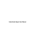
fig. 1 Setup program icon
Key Code Input
The DNASIS Key Code Manager shown in fig. 2 will start up once installation has completed.
fig. 2 DNASIS Key Code Manager
Select Phred/Phrap Option V2.0, click Unlock… to display the Unlock Product dialog shown in fig. 4, and then
enter the key code issued by your Regional Support Center (see Appendix A: User Support Contact Information)
in the Key Code field. Refer to the section on Key Code Issuance Procedures for details on acquiring the key code.
fig. 3 Unlock Product dialog
If the DNASIS Key Code Manager does not start up, select Programs > DNASIS MAX > Key Code Manager
from the Start menu.
4
Phred/Phrap Option Installation and Default Settings
Key Code Issuance Procedures
Fill in the required details on the Key Code Issuance & User Forum Registration Form included in the package,
and either fax or mail it (for email, see below) to your Regional Support Center (see Appendix A). The Key Code
Issuance Notification and User Forum Registration Certificate will be sent back to you by fax and mail.
For e-mail requests, fill in the details for Key Code Issuance and send it to your Regional Support Center by
e-mail. (Be sure to include the Validation Code that came with your software.)
The Machine ID of the computer on which DNASIS MAX Contig Manager Ver2.0 will be installed is also
required for key code issuance. The Machine ID is displayed in the Machine ID field of the Unlock Product dialog
when Unlock on the Key Code Manager is clicked. Be sure to include this machine ID number in your request.
fig. 4 Unlock Product dialog
Tutorial Data
Select Programs > DNASIS MAX > Tutorial Data from the Windows Start menu to open the folder that contains
the tutorial data. The data used by the ContigManager tutorial is stored in the ContigManager folder. Refer to
Chapter 1 Contig Manager Tutorial for details on how to use the tutorial data.
Start up the Contig Manager
Select Programs > DNASIS MAX > Contig Manager from the Start menu. The window shown in fig. 5 will
appear.
fig. 5 Initial window
Chapter 1 Contig Manager Tutorial
8
Chapter 1
Contig Manager Tutorial
This chapter explains the basic operations of the Contig Manager, which enables the sample data to be
used through a series of simple operations.
Chapter 1
Contig Manager Tutorial
9
1.1 Foreword
1.1.1 Contig Manager
The Contig Manager is a user interface that enables sequencing to be carried out with DNASIS MAX Contig
Manager both simply and graphically.
1.1.2 Contigs and Fragments
A contig is a consensus sequence constructed by assembling sequences. A fragment is sequence segment used
for constructing contigs.
1.1.3 Data Management by Project
The Contig Manager enables the entered fragment types, sequences, trimming results, assembled sequence
results, quality values and other data to be managed under single analysis units known as projects.
Multiple projects can be created to allow data management to be performed independently for each user or for
each sequence analysis.
1.1.4 Start up the Contig Manager
Select Programs > DNASIS MAX > Contig Manager from the Start menu to start up the Contig Manager.
1.1.5 Create Projects
The dialog shown below will display when the Contig Manager starts normally.
Open Project dialog
Before using the Contig Manager for analysis, select whether to create a new project or open an existing project
(a list is displayed in the lower part of the dialog) with this dialog. For this tutorial a new project is created.
Select the “Create a new project:” radio button and enter “Sample” in the Project Name text box, and then click
New.
1.1.6 Part Names and Descriptions
10
Chapter 1
Contig Manager Tutorial
The main Contig Manager window shown below will appear when a new project is created.
Map View
Navigation
Tree View
List View
Toolbar
Part Names of Main Contig Manager Window
Item
Description
Map View
Graphically displays a list of contigs that reside in the folder selected in Tree View.
Tree View
Displays the folder hierarchy to manage the sequence data, and a list of contigs.
List View
Displays the contigs and fragments that reside in the folder selected in Tree View, or a list
of the fragments that make up the contig selected in Tree View.
Navigation Toolbar
A group of tools for operating the Contig Manager.
1.1.7 Close the Contig Manager
Select File > Exit from the menu to exit the Contig Manager.
1.1.8 Data Used in the Tutorial
The data used in the tutorial is installed together with the Contig Manager. Select Programs > DNASIS MAX >
Tutorial Data from the Start menu to open the folder that contains the DNASIS MAX tutorial data.
The tutorial use the data contained in the ContigManager folder.
To use this tutorial, you need to install the DNASIS MAX Contig Manager Version 2.0.
Chapter 1
Contig Manager Tutorial
11
1.2 Analysis Example 1 - Assembling Trace Data
This section explains how to use the Contig Manager to load trace data output from sequences, to perform Phred
basecalling, vector trimming and Phrap assembly.
1.2.1 Start up the Contig Manager
Select Programs > DNASIS MAX > Contig Manager from the Start menu to display the Open Project dialog
shown below.
Open Project dialog
1.2.2 Create a Project
1.
Select the “Create a new project:” radio button on the Open Project dialog.
2.
Enter “Tutorial1” in the Project Name text box, and then click New.
3.
The main Contig Manager window appears.
12
Chapter 1
Contig Manager Tutorial
Main Contig Manager window
1.2.3 Enter Trace Data
1.
Select Programs > DNASIS MAX > Contig Manager Tutorial Data from the Start menu to open the
TutorialData folder.
2.
Then open ContigManager > TutorialData1 > TraceData1_1.
3.
Select all of the files contained in the TraceData1_1 folder, and then drag and drop them into the Root
folder in Tree View of the Contig Manager or into the List View.
4.
When dropping the files into Tree View, be sure that the data overlaps the destination folder (the Root
folder in this case).
Chapter 1
Contig Manager Tutorial
13
Drag & Drop
Enter Sequence Data by Drag & Drop
5.
File reading will complete after a few moments. The Import Summary dialog will show the total number
of data, the number and names of imported data, the number and names of skipped data, and the number
and names of error data.
Import Summary dialog
6.
Click OK to close the dialog after first checking the imported fragment contents.
1.2.4 Display Trace Data
1.
A list of the fragments imported in the previous step will appear in List View on the main Contig Manager
window.
14
Chapter 1
Contig Manager Tutorial
Fragments in List View
2.
Double click on any item in the list to display the fragment trace data.
Trace Display using the Trace Viewer
3.
Select View > Show Single Data from the Trace Viewer menu or click on Single Data (
) located on
the Toolbar to display the trace data in multiple stages so that it can be viewed over as wide a range as
possible.
Display Single Trace Data over Multiple Stages
Chapter 1
Contig Manager Tutorial
4.
15
Select multiple fragments from List View in Contig Manager, and then click Open on the Navigation
Toolbar to sort and display multiple trace data.
Display Multiple Trace Data with the Trace Viewer
1.2.5 Trimming Parameter Setup 1
This procedure sets the parameters for erasing vector sequences, sequencing primer sequences and other
elements before the fragments are assembled. Removing these sequences prior to assembly enables the sequences
to be assembled with even higher levels of precision.
Click Detail... under Trimming group on the Navigation Toolbar to display the Trimming Parameters dialog.
Trimming Parameters dialog
16
Chapter 1
Contig Manager Tutorial
This dialog is used to set up the parameters for trimming. Below are parameter descriptions:
Item
Description
Trim End
The parameter for trimming the end of fragments.
Trim at least
Trim the first XX bp, while the
quality is less than XX %.
Trim Vector
The base value for unconditional 5’ and 3’ ends trimming.
The base value for average movement (trim the first XX bp) with the unstable base (N)
percentage for the fragment’s end (quality is less than XX%.)
The parameter for removing vector sequences included in fragments.
Select Vector
The check boxes for selecting vectors to be trimmed.
Select 1 or 2 cloning sites
The check boxes for the cloning sites to be trimmed.
Window size for vector trimming The parameter for setting the base length (window size) to be extracted from the vector
cloning site sequence that is used for determining the vector sequence area. Set with
integers of 15 or higher.
Minimum matching percentage
considered as contamination
The parameter for setting the minimum percentage for matching the vector cloning site
sequence with the sequence targeted for trimming.
Vector sequences that are larger than the percentage set here will be ignored.
Trimming is performed on 5’ ends and 3’ ends with the conditions set for “Trim the first 10bp, while the quality
is less than 90%.” for explanatory purposes in this tutorial.
Note that trimming will not be carried out for registered vector sequences with the sample fragments provided by
the tutorial. Proceed onto the next section on Add Vector Data.
1.2.6 Add Vector Data
1.
Click Vector Database Manager on the Trimming Parameters dialog.
2.
The Vector Database Manager for managing registered vector data will start up.
Vector Database Manager
3.
Click Import... to open the dialog for importing vectors.
Chapter 1
Contig Manager Tutorial
17
Dialog to Import Vector Data
4.
Select ContigManager > TutorialData 1 > TutorialVector from the tutorial data (default:
C:\HSK_DB\TutorialData), select the TutorialVectorA.prm file, and then click Open.
5.
The window will return to the Vector Database Manager, and TutorialVectorA will be added to the vector
list.
6.
Perform the same procedure for TutorialVectorB.prm and TutotialVectorC.prm to add a total of three vectors.
When registering the vectors to be trimmed with actual analysis data, add any of the vectors from the
VectorData folder (default: C:\HSK_DB\VectorData) that is specified beneath the Database directory when
DNASIS MAX is installed. (If the location cannot be found, select Programs > DNASIS MAX > Tutorial Data
from the Start menu. The required folder is in the first hierarchy of folders in the database.)
This folder contains more than 900 different types of vector data. Refer to the VectorTable.txt file located in the
VectorData folder for details. This file can be easily viewed with Microsoft Excel or another spreadsheet
application.
7.
Register the vector, and then click Close to end the Vector Database Manager.
1.2.7 Trimming Parameter Setup 2
This procedure sets the parameters required trimming using the vectors added in the previous section on Add
Vector Data.
1.
Select the Trim Vector check box on the Trimming Parameters dialog.
2.
Select the TutorialVectorA check box on the Select Vector list.
3.
Select the PrimerA check box on the Cloning Sites list.
Select the vector and cloning site check boxes
18
Chapter 1
Contig Manager Tutorial
4.
Repeat the same procedure to select the TutorialVectorB and PrimerB check boxes, and the
TutorialVectorC and PrimerC check boxes.
Check the imported vectors and corresponding cloning sites when performing actual analysis.
5.
Set a value that is lower than the default value for the “Minimum matching percentage considered as
contamination:” parameter with the tutorial data. Amend the default value to 85%.
6.
Click OK to close the Trimming Parameters dialog once this setting has been made.
7.
Return to the main window, and select the Trimming check box on the Navigation Toolbar.
1.2.8 Perform Auto Assemble
This section explains how to perform basecalling, trimming and assembly of trace data.
1.
Select all of the fragments displayed in List View on the main Contig Manager window (an easy way to
select all data is to click on any data item in List View then press Ctrl + A or select Edit > Select All from
the menu).
2.
Confirm that all fragments are highlighted then click Auto Assemble on the Navigation Toolbar.
If the Use Phred check box was selected under the Basecall group, Phred basecalling will be performed with
assembly taking into account the quality values (QVs). If the check box is not selected, assembly will be
performed based on the trace’s internal basecall data, without regard to the QVs.
3.
The contig sequence information is added to Tree View once analysis is completed.
New contigs
4.
Trimming results and direction information are added to each fragment in List View.
The List View with the new information added
Chapter 1
Contig Manager Tutorial
19
In the example above, the length of fragment 30194804 is 927bp after trimming, the trimmed bp count is 24bp,
the name of the vector used for trimming is TutorialVectorA, the number of base pairs within the range set as Low
QV with the QV as 379bp, the basecall procedure was performed with Phred, trimming has been completed, and
assembly was carried out with the normal strand.
The details for each column are listed below:
Item
Description
Icons by data type
Indicates the data type.
The icon attached to fragments that possess trace data.
The icon attached to fragments that possess only sequence data.
The icon attached to fragments that have been entered as trace data, but for which the trace
data has been moved or deleted.
The icon attached to contigs.
Name
Displays the name of the corresponding data.
Length
Displays the sequence length of the corresponding data.
Trimmed Len.
Displays the total bp count of the trimmed area when trimming has been performed.
This column remains blank if trimming is not performed or no fragments were trimmed.
Vector
Displays the name of the vector for which trimming was performed.
Low QVs
When using Phred basecalling, displays the number of bases in bp units that are within the
range of Low QVs set in View > Preferences from the menu.
Phred icon
Displays if Phred basecalling is performed on the fragment.
Trimming icon
Displays if the fragment has been trimmed. It will also display even if trimming was not
performed.
Assembly Direction Icon
Indicates the direction in which the fragment was assembled. Data that does not display
this icon has not been assembled.
This icon is displayed when assembly has been performed with the same strand as the
entered sequence.
This icon is displayed when assembly has been performed with complementary strands of
the entered sequence.
Comment
Displays a character string when a comment has been entered for the corresponding data.
20
Chapter 1
Contig Manager Tutorial
1.2.9 Display Contig Results
1.
Select any of the contigs displayed in Tree View on the main window to display the fragment information
of the new contig.
2.
A list of the fragments forming the contig selected from the List View together with each assembly
direction will display.
List of Fragments Forming the Contig
3.
Double click Contig1 on the Tree View.
4.
The Contig Viewer will start up, and the status of the Contig1 fragment assembly will be displayed
graphically.
Map View
Sequence View
Graphical Display of the Composition
The Contig Viewer is divided into top and bottom panes. The top pane graphically displays the entire subject
(Map View) and the bottom (Sequence View) displays the contig sequence (top stage) and each fragment
sequence.
Chapter 1
Contig Manager Tutorial
21
1.2.10 Sort and Display Trace Data
Actual trace data can be sorted and displayed to evaluate assembly results.
1.
Click the base value for the trace that is to be sorted and displayed on the contig sequence, and then either
select View > Chromatograms from the menu, or click Show Chromatograms (
) with the base value
highlighted.
Highlighted base values
2.
The trace data will be aligned and displayed based on the selected base value.
Trace data sorted and displayed
3.
The status of the trace data display is linked into the selected position of the sequence in the Contig
Viewer and can be changed accordingly. Click the contig sequence in the Contig Viewer or the base value
on the fragment sequence to re-sort and display the trace data based on the selected base value.
22
Chapter 1
Contig Manager Tutorial
The linked display of the trace data when the base value on the contig is clicked
The linked display of the trace data when the base value on the fragment is clicked
1.2.11 Reassembly
This section explains how to add a new sequence and perform reassembly with the added fragments included.
1.
Select Programs > DNASIS MAX > Tutorial Data from the Start menu to open the TutorialData folder.
2.
Then open ContigManager > TutorialData1 > TraceData1_2.
3.
Drag and drop the data contained in the folder to the Root folder in Tree View.
4.
The name of the sequence and the number involved entered on the Import Summary dialog will be
displayed. Click OK to close the dialog.
5.
Select the Root folder in Tree View and confirm that the corresponding fragments have been added to the
List View.
6.
Select the required fragment and click Basecall on the Navigation Toolbar to perform Phred basecalling
and calculate the quality value.
7.
Select the corresponding fragment and click Trim on the Navigation Toolbar to perform the vector
trimming.
8.
Select all of the fragments in the List View and press Assemble. A message stating, “Some of the selected
fragments are connected. Are you sure to dissolve the connection and continue operation?” will appear.
Click Yes to continue with the process.
Chapter 1
Contig Manager Tutorial
9.
23
The assembly process will be performed including the added fragments, and a new contig sequence will
be created.
10. These will be assembled into a single contig if the tutorial data is used.
1.2.12 Exit the Contig Manager
Select File > Exit from the Contig Manager’s menu if analysis has completed.
24
Chapter 1
Contig Manager Tutorial
1.3 Analysis Example 2 - Sequence Clustering and DNASIS MAX Links
This section explains how to perform clustering on the EST sequences registered in Genbank using the Contig
Manager. It also explains how to perform simple analysis of new contig sequences with the use of DNASIS MAX.
1.3.1 Start up the Contig Manager
Select Programs > DNASIS MAX > Contig Manager from the Start menu to display the Open Project dialog
shown below.
Open Project dialog
1.3.2 Create a Project
1.
Select the “Create a new project:” radio button on the Open Project dialog.
2.
Enter “Tutorial2” in the Project Name text box, and then click New to open the main Contig Manager
window.
Chapter 1
Contig Manager Tutorial
25
Main Contig Manager Window
1.3.3 Enter Trace Data
1.
Select Programs > DNASIS MAX > Tutorial Data from the Start menu to open the TutorialData folder.
2.
Open ContigManager > TutorialData2 > TraceData2_1.
3.
Select all of the files contained in the TraceData2_1 folder, and then drag and drop them into the Root
folder on the Tree View of the Contig Manager or into the List View.
Drag & Drop
4.
File reading will complete after a few moments. The Import Summary dialog will show the total number
of data, the number and names of imported data, the number and names of skipped data, and the number
and names of error data.
26
Chapter 1
Contig Manager Tutorial
Import Summary dialog
5.
Click OK to close the dialog.
1.3.4 Sequence Assembly
1.
Select all fragments added to the List View on the main Contig Manager window.
Select any data item in List View, and then press Ctrl + A, or select Edit > Select All from the menu to select all
fragments.
2.
Click Assemble on the Navigation Toolbar.
3.
The assembled contigs will appear in Tree View.
Composition Results
4.
36 contigs will be created if analysis is performed with the default values. This may be interpreted as the
entered fragment groups forming 36 clusters.
Chapter 1
Contig Manager Tutorial
27
1.3.5 Adjust the QV Threshold
It is possible to specify different colors for the Map View and set up high/low threshold values as the parameters
for the Low QVs count in Tree View and List View. In this tutorial, low QV can be changed from 1 to 29 and high
QV from 30 to 99.
1.
Select View > Preferences… from the menu, or click Preferences (
) on the Toolbar to display the
Preferences dialog.
Preferences dialog
2.
Change the value circled in the dialog above between 20 and 30 then click OK to close the dialog.
3.
The Map View will be redrawn, and the values in Tree View and List View will be re-calculated.
1.3.6 Examine Assembly Results
Contig34 created through analysis with the default values is used in this tutorial.
Contig34
The view above shows a Contig34 length of 2807bp, consisting of 48 fragments, and a base value of 1758bp for
the QV (set at 30 or less for this example.) It is also clear that the low quality areas are situated on both ends and in
the center of the contig.
1.3.7 Display Assembly Status Details
1.
Double click on Contig34 to view actual assembly details in List View.
28
Chapter 1
Contig Manager Tutorial
Map View
2.
The layout of fragments in Map View of the Contig Viewer indicates that both ends of the contig have
been read comparatively well, whereas the central area has not.
3.
Viewing the sequence enables us to estimate that a Poly-A region exists near the 3’ end of the contig
sequence.
Poly-A Region
1.3.8 Link with DNASIS MAX
1.
Select File > Export Contig to DNASIS MAX from the Contig Viewer menu, or click Export Contig to
DNASIS MAX (
2.
) on the Toolbar to analyze the new contig sequence with DNASIS MAX.
DNASIS MAX will start up when the contig sequence is read.
DNASIS Start Up window
Chapter 1
Contig Manager Tutorial
3.
29
Try an ORF search at this point by clicking ORF in the DNA-Search group. And click Execute in the
Analysis dialog. The analysis will be performed and results similar to those shown below will appear.
ORF search results
4.
These results show that errors still exist in the contig sequence.
5.
As shown by the contig’s quality value the sequence accuracy between values close to 1150bp to values
close to 2050bp are relatively low. The next step is to design a primer for increasing sequence accuracy by
performing sequencing with the use of the primer working method from areas with high levels of
sequence precision.
6.
Select 1050bp to 1100bp from the DNASIS MAX contig sequence, and then press Primer Design in the
DNA-Search group. A primer that increases the width of the relevant area will be designed when the
sequence is selected.
Result of Primer Design
7.
By performing analyses and linking with DNASIS MAX and by repeating the primer design, sequencing
and re-assembly in this way, it is possible to increase the accuracy of the contig sequence.
1.3.9 Manage Sequence Data by Folder
The most convenient method to manage a large volume of sequence data is to create hierarchical folders in Tree
View and manage the sequence data by folder.
Managing sequence data by folder without dividing the projects enables work to be efficiently and simply
carried out for such tasks as sequence clustering with contig creation, adding sequences and performing
re-assembly after contigs have been created.
30
Chapter 1
Contig Manager Tutorial
1.3.10 Create a New Folder
1.
Right click the Root folder and select New Folder from the popup menu that appears.
Popup menu
2.
A folder named New Folder(1) is created under the Root folder.
New Folder
3.
Right click the new folder and select Property... from the popup menu that appears. The Property dialog
appears.
4.
The first text box of the dialog is for the folder name, which can be changed.
5.
For this Tutorial use TutorialFolder1.
Property dialog
1.3.11 Move Fragments
Fragments and contigs are moved to other folders by dragging and dropping. For example, the following
explains how to move all the fragments that make up Contig34 to TutorialFolder1.
1.
Select Contig34 from the Tree View to display a list of fragments that make up Contig34 on the List
View.
2.
Select all the fragments in ListView. Drag and drop all fragments into the TutorialFolder1.
3.
The selected fragments move to TutorialFolder1.
Chapter 1
Contig Manager Tutorial
31
1.3.12 Add Sequence Data
This section explains how to add sequence data from sequencing using a combination of DNASIS MAX features
like primer design and others.
1.
Select Programs > DNASIS MAX > Tutorial Data from the Start menu to open the TutorialData folder.
2.
Then open ContigManager > TutorialData2.
3.
Select TutorialData2_2.txt from the TutorialData2 folder, and then drag and drop it into the
TutorialFolder1 folder on the Contig Manager’s Tree View.
4.
File reading will complete after a few moments. The Import Summary dialog will show the total number
of data, the number and names of imported data, the number and names of skipped data, and the number
and names of error data.
Dropping this file into TutorialFolder1 enables the fragments contained in the folder to be read directly.
1.3.13 Sequence Assembly With Only the Sequence Data Contained in the
Folder
1.
Click TutorialFolder1 in Tree View to display a list of the contigs and fragments contained in the folder in
List View.
2.
Select all of the fragments in List View and click Assemble on the Navigation Toolbar.
3.
A message stating, “Some of the selected fragments are connected. Are you sure to dissolve the
connection and continue operation?” will appear. Click Yes to continue with the process.
4.
The assembly process will be performed, and Contig37 will be created immediately beneath
TutorialFolder1.
32
Chapter 1
Contig Manager Tutorial
Contig37
5.
Clearly, adding fragments and re-assembling the data has reduced the low region quality value from
1758bp to 1402bp, and that the accuracy of the contig sequence has been improved.
1.3.14 Dissolve Assembled Sequences
To dissolve assembled sequences, select the contig assembly to dissolve from Tree View or List View, and then
click Dissolve on the Navigation Toolbar. In this example, Contig36 will be dissolved. A new folder will also be
created for easy confirmation of dissolving results. All fragments will be moved to this folder to perform
dissolving.
1.
Right click on the Root folder, and then select New Folder from the popup menu.
2.
Right click on the New Folder (1) created in the previous step, and then select Property... from the popup
menu.
3.
The Property dialog for the folder will appear. Amend the folder name from New Folder (1) to
TutorialFolder2.
4.
Select Contig36 from Tree View to display a list of fragments that make up this contig in List View.
5.
Click on any item of data displayed in List View, and then press Ctrl + A, or select Edit > Select All from
the menu.
6.
Drag and drop the fragments selected in List View and move them to TutorialFolder2.
7.
Select Contig36 from the List View, and then click Dissolve on the Navigation Toolbar.
8.
A confirmation dialog with a message, “Are you sure to dissolve contigs?” will display. Click Yes to
continue with the dissolving process.
9.
Click TutorialFolder2 on the Tree View to display a list of all fragments contained in that folder (the
fragments that make up Contig36). The absence of the icons that indicate the assembled status confirms
that assembled sequence has been dissolved.
Chapter 1
Contig Manager Tutorial
33
1.3.15 Search for Fragments
Fragment names can be specified to run searches on which folder or contig they belong to. Wildcards can be used
as search strings to enable fragment names that share specific patterns to be retrieved as efficiently as possible.
1.
Click Fragments on the Navigation Toolbar.
2.
Check Fragment dialog appears.
Check Fragment dialog
N a v i g a t i o n To o l b a r D e s c r i p t i o n
1. Select target folder / contig
Select the folder or contig for the search target.
2. Pattern1 - Pattern10
Enter the name of the fragments for which the search is to be run. Searches can be run with
a maximum of ten fragments.
The following two methods are available for specifying the wildcard:
*: Random character strings
?: Single random character
Names that represent perfect matches and names that include the wildcard can be entered.
3. Find Results
Displays a list of the fragments found that match the search strings.
4. Fragments
Displays a list of the fragments found during the search.
3.
Enter AA494612 in Pattern 1, AI* in Pattern 2, *12 in Pattern 3, and AA49???? in Pattern 4.
34
Chapter 1
Contig Manager Tutorial
Search Pattern Entry
• A494612: Searches for data with a sequence name of AA494612.
• AI*: Searches for data for which the sequence name starts with AI.
• *12: Searches for data for which the sequence name ends with 12.
• AA49????: Searches for data for which the sequence name starts with AA49 and contains four other random
characters consecutively.
4.
Select all of the contigs and folders on the Select target folder/contig list, and then click Find.
When selecting multiple elements from the list, click the mouse button while pressing the Ctrl button to add
required selections, or click the mouse button while pressing the Shift button to sequentially select all of the data
between the first click and the second click.
Number of search
Search target
results
for
each
pattern.
Search result
5.
The Find Results shows that the AA494612 fragment entered in Pattern 1 resides in TutorialFolder1, and
those three fragments that start with the AI entered in Pattern 2 reside in Contig6, 1 in Contig9, 60 in the
Root folder, 26 in TutorialFolder1, and 10 in TutorialFolder2.
6.
Click on the cell for search results to display a list of the fragments that match the search conditions in the
Fragments list.
Chapter 1
Contig Manager Tutorial
Fragment search result list
7.
Double click on any of the fragments displayed on the Fragments list to display the sequence for that
specific fragment.
8.
Trace data will be displayed together with the sequence if fragments that possess trace data are found.
Fragment sequence display
Fragment trace display
35
36
Chapter 1
Contig Manager Tutorial
1.4 Analysis Example 3 - Analyses Using Phred Quality Values
This section explains how to run homology searches using sequence selection and only high quality regions based
on Phred quality values.
*The DNASIS MAX DNASpace option is required for this tutorial.
1.4.1 Start up DNASpace and Opening Space
1.
Select Programs > DNASIS MAX > DNASpace from the Start menu.
2.
The Open Space dialog shown below will appear.
Open Space dialog
3.
Select “A-09. Blast Search with Phred QV” from the list. Click Open and the following space appears.
A-09. Blast Search with Phred QV
Chapter 1
Contig Manager Tutorial
37
1.4.2 Set Sequence Masks and Selection Parameters of Quality Values
1.
Double click on Phred Quality Value Masking on the Space dialog to open the Parameter Set Editor.
Phred QV Masking Parameterset Editor
Item
Description
Masking Parameters
Sets the masking parameters based on the input sequence quality value.
5’ End
Sets whether or not to perform masking with the QV set for the 5’ end sequence. Select
this check box to perform masking.
Mask while moving average of Obtains the moving average of the QV from the 5’ end and performs masking while the
QV is less than or equal to XX average value is XX or less. Masking ends when the average value exceeds the value
specified here.
Moving average window size
Specifies the window size for obtaining the moving average when masking with 5’ end
sequences.
Mask as N
Select this check box if the base value is to be replaced with N for the relevant region
when the moving average of the 5’ end sequence’s QV is the same or less than the
threshold value.
3’ End
Sets whether or not to perform masking with the QV set for the 3’ end sequence. Select
this check box to perform masking.
Mask while moving average of Obtains the moving average of the QV from the 3’ end and performs masking while the
QV is less than or equal to XX average value is XX or less. Masking ends when the average value exceeds the value
specified here.
Moving average window size
Specifies the window size for obtaining the moving average when masking with 3’ end
sequences.
Mask as N
Select this check box if the base value is to be replaced with N for the relevant area when
the moving average of the 3’ end sequence’s QV is the same or less than the threshold
value.
Middle
Sets whether or not to perform masking with the QV set for the entire sequence. Select
this check box if masking is to be performed.
Mask while moving average of Obtains the moving average of the QV from the closest 5’ end to the closest 3’ end of
QV is less than or equal to XX non-masked regions, and performs masking while the average value is XX or less.
Moving average window size Specifies the window size for obtaining the moving average when masking with the entire
sequence.
Mask as N
Select this check box if the base value is to be replaced with N for the relevant region
38
Chapter 1
Contig Manager Tutorial
Item
Description
when moving average of the entire sequence’s QV is the same or less than the threshold
value.
Output Parameters
Sets the parameters for the folder where masking result data is output.
If high QV bp is less than or equalThe results are output to the “NG” folder if the length of unmasked region is XXbp or less
to XX bp, output to “NG” folder when this check box is selected.
2.
In this tutorial, the threshold of the QVs for both ends are set to 29, the threshold of the QVs for the entire
sequence are set to 19, and the bp count of the high quality regions to be output to the NG folder is set at
500bp and lower.
Masking Parameters
Output Parameters
1.4.3 Trimming Setup
This tutorial uses the vector registered in section 1.2. If the relevant vector has not been registered, refer to 1.2.6
“Add Vector Data” to register the vector before continuing with this tutorial.
1.
Double click ***** Double click this to set the vector. ***** to open the trimming settings dialog.
2.
Select the Trim End check box at the top, and then set 5’ End to “Trim the first 10bp, while the quality is
less than 90%”, and 3’ End to Same as 5’ End.
Chapter 1
Contig Manager Tutorial
3.
39
Select the Trim Vector check box, select TutorialVectorA from the Vector Name: list, and then select
PrimerA from the Cloning Site: list.
Trimming setup
4.
Close the dialog with OK once the settings have been made.
1.4.4 Blast Search Setup
Double click ***** Double click this to set database ***** to open the parameter setup dialog.
Select the target
database check box.
Blast Parameters dialog
It is not necessary to modify the parameters for use with this tutorial. When performing actual analyses, set the
target search database and other details in this dialog.
40
Chapter 1
Contig Manager Tutorial
1.4.5 Enter Trace Data
1.
Select Programs > DNASIS MAX > Contig Manager Tutorial Data from the Start menu, and then open
the TutorialData folder.
2.
Open the ContigManager > TutorialData1 > TraceData1_1 folder.
3.
Select all of the files contained in the TraceData1_1 folder, and drag and drop them into the ***** Drop
trace data here ***** folder in the Space dialog.
4.
The progress dialog will appear, and then close when processing has completed.
Progress dialog
Chapter 1
Contig Manager Tutorial
41
1.4.6 Results
1.
Data will accumulate in the folders located in the Space window when the processing has completed.
Double click ***** Drop trace data here ***** and confirm that the entered trace data has been saved.
Data confirmation in the Space window
2.
Double click on any item listed in the selected folder to display data details.
Trace data
3.
The Phred basecall data is saved in the ***** Basecall result by Phred ***** folder. Double click this
data to display the trace data. The original basecall, the Phred basecall, the Phred QV, and the trace data
can be viewed.
Original Basecall
Phred Basecall
Phred QV
Trace data
Results of Phred
42
Chapter 1
Contig Manager Tutorial
4.
The vector sequences deleted with trimming are output to the ***** Trimmed sequence. ***** folder. Of
the 30 items of data input with this tutorial, 17 have been vector trimmed. This shows the vectors regions
replaced with N.
Trimming Results
5.
The vector sequences that could not be deleted are output to the ***** No trimmed sequence ***** folder.
Of the 30 items of data input with this tutorial, 13 have been separated as data that could not be vector
trimmed.
6.
The results of Phred QV masking and the data for which the high quality region bp count is longer than
the threshold value (500bp with the tutorial) are output to the ***** High quality region is short. *****
folder. Of the 17 items of trimmed data input with this tutorial, 12 items of data are judged to have long
high quality regions. Double click on the data to display the results and show the low quality regions
masked by N.
.
Masking results with Phred QV
7.
The data for which the high quality region bp count is shorter than the threshold value is output to the
***** High quality region is short. ***** folder. Of the 17 items of trimmed data input with this tutorial,
5 are judged to have short high quality regions.
8.
The Blast search results that have vector sequences were deleted, high quality regions longer than 500bp
and the low quality regions have been masked by N are output to the ***** Blast Search Result *****
folder. Double click on the data to display the search results graphically.
Chapter 1
Contig Manager Tutorial
Blast search results
43
Chapter 2 Window Descriptions
Chapter 2
Window Descriptions
47
2.1 Online Help
Online Help is available in Contig Manager. Select Help > Contents from the menu or click
Also, by clicking Help of each dialog, Help for the dialog will appear.
on the Toolbar.
2.2 Project Window
Toolbar
Menu Bar
Navigation Toolbar
Map View
List View
Tree View
View Switchover Tab
Status Bar
48
Chapter 2
Window Descriptions
2.2.1 Menu
File menu
Description
New
Opens a new project in a new window. Displays Open Project dialog.
Open
Opens a specified project file. It is also possible to specify multiple files to open.
Revert
Returns the project to the pre-edit status. If the project was not saved, returns the project to
the status when opened.
Save Project
Stores a project by overwriting it.
Print Setup...
Displays the Set Printing Information dialog and gives the setting of the paper size and
printer information.
Print Preview
Displays a print image.
Print...
Carries out printing.
Import
Obtains a specified project or sequence.
Import Project…
Imports a project.
Merges the data of other project with the currently opened project.
Import Sequence…
Reads the sequence from the specified file.
Export Sequence
Stores a sequence by giving it a name.
Export Original Sequence...
Stores a sequence by giving it a name before trimming or assembly.
Export Sequence...
Stores a specified sequence in the List View by giving it a name.
Exit
Terminates the Contig Manager.
Edit menu
Description
Copy
The active view decides the target of copy.
When Map View is active:
The shapes drawn by Map View are copied to Clipboard.
When Tree View is active:
The data is copied as text data to Clipboard, with all the data hierarchies of the Tree View
open. The depth of each hierarchy is expressed with the number of tabs at the line head, so
when pasted to applications such as Microsoft Excel, browsing becomes easy.
When List View is active:
The information highlighted on List View is copied to Clipboard as tab delimited text.
Delete
Deletes a selected folder, fragment, or contig.
Select All
When Map View is active, every contig displayed in Map View is highlighted. When List
View is active, every fragment and contig displayed in List View is highlighted.
Deselect All
Every selection made in the active view is canceled.
View menu
Description
Map View
Views/hides the Map View.
Check Fragments Composition...
Displays the Check Fragments dialog. For details refer to 2.2.11 “Check Fragments
dialog”.
Open Data...
Opens the highlighted data in the active view.
Summary...
Displays the Import Summary dialog. For details refer to 2.2.10 “Import Summary
dialog”.
Navigation Tool bar
Views/hides the Navigation Toolbar.
Standard Toolbar
Views/hides the Standard Toolbar.
Status Bar
Views/hides the Status Bar.
Preferences...
Displays the Preferences dialog. For details refer to 2.2.8 “Preferences dialog”.
Chapter 2
Window Descriptions
49
Contig menu
Description
New Folder
Creates a new folder. This feature is enabled when Tree View is active and a folder is
selected. The new folder is created under the selected folder.
Assemble
Assembles what is selected in List View such as fragments.
Basecall
Performs basecall assembly of the trace data selected in List View from the Basecall
setting on the Navigation Toolbar.
Trimming
Removes terminal regions with numerous N’s and vector sequences from fragments
selected in List View. Refer to 2.2.15 “Trimming Parameter dialog” for setting details.
Phrap Assemble
Assembles fragments selected in List View, utilizing Phrap. Refer to 2.2.13 “Phrap
Parameter dialog” for setting details. To use Phrap, you need to install the Contig
Manager.
DNASIS Assemble
Automatically searches and assembles the fragments selected in List View. Refer to
2.2.12 “DNASIS Assemble Parameter dialog” for setting details.
Auto Assemble
Based on the Navigation Toolbar settings, performs basecalling, trimming and assembly
of fragments selected in List View.
Dissolve Contig
Removes the contig alignment selected in the currently active view.
Remove Selected Sequence
Removes contig fragments selected in List View. Reassembles the contig without the
fragments selected for removal.
Copy Contig As Fragment
Copies the selected contig as a fragment. When reassembling the contig, use the copied
fragment.
Relink Trace Files...
Resets the links to trace files. Refer to 2.2.16 “Relink Trace Files dialog” for setting
details.
Parameters...
Displays the parameter setting window.
Trimming...
Sets the trimming parameters. Refer to 2.2.14 “Trimming Parameter dialog” for setting
details.
Vector DB Manager...
Sets the Vector Database Manager. Refer to 2.2.15 “Vector Database Manager dialog” for
setting details.
Phrap...
Sets the Phrap parameters. Refer to 2.2.13 “Phrap Parameter dialog” for setting details.
DNASIS Assemble
Set the parameters for DNASIS Assemble. Refer to 2.2.12 “DNASIS Assemble Parameter
dialog” for further details.
Property...
Displays the folder, contig and fragment information selected in Tree View or List View.
The names and comments can be edited.
Help menu
Description
Contents
Displays online help.
User Forum Web Page
Displays the User Forum website of DNASIS MAX. Requires connection to the Internet.
About Contig Manager...
Displays the version information.
2.2.2 Toolbar
Icon
Description
Opens a new project in a new window. Displays Open Project dialog. The same as selecting File > New from
the menu.
Opens a specified project file. It is also possible to specify multiple files to open. The same as selecting File
> Open… from the menu.
Stores a project by overwriting it. The same as selecting File > Save Project from the menu.
Not supported in the current version.
50
Chapter 2
Window Descriptions
Icon
Description
Copies data selected in Tree View or List View to the clipboard. The same as selecting Edit > Copy from the
menu.
Not supported in the current version.
Carries out printing. The same as selecting File > Print from the menu.
Displays a print image. The same as selecting File > Print Preview from the menu.
Displays the Preferences dialog. For details refer to 2.2.8 “Preferences dialog”. The same as selecting View
> Preference… from the menu.
Displays online help. The same as selecting Help > Contents from the menu.
2.2.3 Navigation Toolbar
Item
Description
Auto Assemble
Based on the Navigation Toolbar Settings, performs basecalling, trimming and assembly.
Basecall
Sets trace basecall parameters.
Use Phred
Basecall
Trimming
Selects the parameter to use for basecalling.
Original:
Basecalling using the sequence information stored in the trace file.
Phred:
Basecalling using Phred. To use Phred, you need to install the Contig Manager.
Perform a basecall using the trace selected in List View.
Performs trimming if Auto Assemble is checked.
Detail...
Displays the Trimming Parameter dialog. Refer to 2.2.14 “Trimming Parameter dialog”
for setting details.
Trim
Trims the fragments selected in List View based on the settings in Detail....
Assemble
Method
Sets the assembly parameters.
Selects the algorithm to use for assembling.
DNASIS Assemble:
Aligns using DNASIS Assemble.
Phrap:
Chapter 2
Window Descriptions
Item
Fwd. Primer
51
Description
Aligns using Phrap. When Phrap is selected, the following parameters will be
displayed. To use Phred, you need to install the Contig Manager.
Trace data is forward read using the dye primer method and when distinct name patterns
are identified for a fragment they are input. Forward linking is given priority if the
direction cannot be determined.
Rev. Primer
Trace data is reverse read using the dye primer method and when distinct name patterns
are identified for a fragment they are input. Reverse linking is given priority if the
direction cannot be determined.
Fwd. Terminator
Trace data is forward read using the terminator method and when distinct name patterns
are identified for a fragment they are input. Forward linking is given priority if the
direction cannot be determined.
Rev. Terminator
Trace data is reverse read using the terminator method and when distinct name patterns
are identified for a fragment they are input. Reverse linking is given priority if the
direction cannot be determined.
Detail...
When selecting DNASIS Assemble in Method:
Displays the DNASIS Assemble Parameter dialog. Refer to 2.2.12 “DNASIS Assemble
Parameter dialog” for details.
When selecting Phrap in Method:
Assemble
Displays the Phrap Parameter dialog. Refer to 2.2.13 “Phrap Parameter dialog” for
details.
Assembles the fragments selected in List View based on the settings.
Jump
Searches for fragments. Enter the name of the fragment you want to search in the box and
click Jump.
Fragments with identical names will be selected when List View is active.
Open
Opens the selected fragment or contig in an active view.
Dissolve
Removes the contig alignment selected in the currently active view.
Remove
Removes contig fragments selected in List View. Reassembles the contig without the
fragments selected for removal.
Fragments…
Displays Check Fragment dialog. Refer to 2.2.11 “Check Fragment dialog” for setting
details.
Reset To Original Sequence
Returns the selected fragments to the sequence at the time of input. When the fragments
are linked, the links are removed.
2.2.4 Status Bar
The Status Bar displays the names of each menu button of menu and Toolbar at the mouse cursor, and each
application on the application palette.
2.2.5 Map View
Map View graphically displays the project contigs with quality values. Refer to 3.11.1 “Map View” for the
details.
2.2.6 Tree View
Tree View displays the project structure, with folders, contigs, and fragments that compose it. Refer to 3.11.2
“Tree View” for the details.
52
Chapter 2
Window Descriptions
2.2.7 List View
List View displays the contents of the folder selected in Tree View. Refer to 3.11.3 “List View” for the details.
2.2.8 Preferences dialog
Settable Range
Displaying colors of
Contig
Item
Description
Quality score is between X and Y
Sets the boundaries when coloring the contigs in Map View based quality values.
Boundary values can range is from 1 to 99.
Displaying colors of Contig
Sets the display color when quality value is within the set range. When double clicking
the display color with the mouse the color setting dialog will display.
2.2.9 Open Project dialog
Item
Create a new project
Description
Creates a new project.
Project Name
Enter a project name. Up to 120 characters can be used. The following characters cannot
be used in the project name:
()*=|![]@{};?\,/
New
Creates a new project with the name input in the Project Name textbox.
Open existing project
Opens an existing project.
Server Name
Specifies the server to store data. In the current version, the server cannot be changed.
Select Projects
Displays a list of existing projects.
Chapter 2
Window Descriptions
Item
53
Description
Delete
Deletes the project selected in the Select Projects list.
Duplicate
Copies the project selected in the Select Projects list. After pushing the button you will be
prompted to enter a new name, which is required.
Rename
Renames the project selected in the Select Projects list.
Export…
Exports the project selected in the Select Projects list. The whole project can be stored in a
file.
Import…
Imports the project exported in Export…. Project names can be specified for import.
Open
Opens the project selected in the Select Projects list.
Exit
Closes the Open Project dialog.
2.2.10 Import Summary dialog
When the imported data is not an ACE file, the dialog displays the contents of the imported data.
Item
Description
The number of processed data
Displays the number of data processed for import.
Import Data
Displays a list of the imported data. Also displays the names and sequence length. The
data can be sorted by clicking each column header.
Skip Data
Specifies files to skip when trying to import data with the same name as data already
present. The data can be sorted by clicking each column header.
Error Data
Displays data failed to import. The data can be sorted by clicking each column header.
# of data
Displays the number of imported data.
# of overwrite data
Displays the number of data overwritten on importing.
OK
Closes the dialog.
54
Chapter 2
Window Descriptions
2.2.11 Check Fragment dialog
Item
Description
Select target folder/contig
Selects the search target folder or contig.
Pattern
Input the fragment name for search. Up to ten fragments can be searched. * and ? are
available as wild cards.
*: any string
?: any one character
Find Results
Lists the number of fragments found with the search string.
Fragments
Displays a list of fragments found with the search string.
Name
Displays the name of the fragment.
Length
Displays the length of the fragment.
Trimmed Length
Displays the length of the region masked by trimming.
Trimmed Vector
If masked by a vector sequence in trimming, displays the name of the vector.
Low Quality bps
For fragments resulting from Phred basecalling of a trace, the total bp number in the
region where the Phred QV value of the fragment is low will display.
Connected
Displays the process done to the corresponding fragment.
Comment
Phred: Phred basecalled fragments
Trimmed: Trimmed fragments
Assemble(N): Fragments linked with a Normal strand
Assemble(C): Fragments linked with a complementary strand
Displays the comment of the corresponding fragment.
Chapter 2
Window Descriptions
55
2.2.12 DNASIS Assemble Parameter dialog
Parameterset Editor
Item
Description (Initial setting)
Min_Overlap_Length
Sets the minimum overlap of the fragments necessary to determine whether the pieces of
the fragments can be linked. The setting can range from 1 to 100, and it cannot be smaller
than the value set in Homology_Compare_NA. (30)
Min_Match_Rate
Sets the minimum percentage of the matching fragments to determine whether the pieces
of the fragments can be linked. The setting can range from 1 to 100. (90)
Homology_Compare_NA
Sets the number of bases (bp) to compare when searching for regions of fragment
homology. The starting and ending points for searches will be perfectly identical points,
more than the number of bases set here. The setting can range from 1 to 6. (4)
MaxMatch_Compare_NA
Sets the number of bases (bp) to compare in the maximum matching of fragments. When
the part to compare is greater than the number of bases set here, the ends of the part to
compare will be repeatedly compared by half the value set here. The setting can range
from 200 to 500. (200)
Contig_Header
To embed MIME information, sets the header name for contig information (the actual
name of a contig will be “the value set here + the order of creation”). Value up to 64 letter
characters, both capitals and lower cases, and the underbar. (_)
56
Chapter 2
Window Descriptions
2.2.13 Phrap Parameter dialog
Scoring of pairwise alignments
Item
Description (Initial setting)
penalty
Sets the mismatch penalty for SWAT comparisons. ( -2)
gap_init
Sets the gap initiating penalty for SWAT comparisons. ( -2)
gap_ext
Sets the gap extension penalty for SWAT comparisons. ( -1)
raw
Uses raw rather than the existing Smith-Waterman scores. (-)
Chapter 2
Window Descriptions
57
Others
Item
Description (Initial setting)
minmatch
Sets the minimum length of matching word to nucleate SWAT. If the value is set to 0, the
matching process will terminate. (14)
bandwidth
Sets the region value at half band width for banded SWAT search. (Full width is 2n+1.)
(14)
minscore
Sets the minimum SWAT score. (30)
vector_bound
Sets the number of bases at the beginning of each read, matches within which are assumed
to be a vector. (60)
node_seg
Sets the minimum segment size. (8)
node_space
Sets the spacing width between nodes. (4)
58
Chapter 2
Window Descriptions
Miscellaneous
Item
Description (Initial setting)
trim_penalty
Sets the penalty for identifying a degenerate sequence at beginning/end of a read. (-2)
trim_score
Sets the minimum score for identifying a degenerate sequence at beginning/end of a read.
(20)
confirm_length
Sets the minimum size of confirming segments. (8)
confirm_trim
Sets the amount by which confirming segments are trimmed at the edges. (1)
confirm_penalty
Sets the penalty used in aligning against “confirming” reads. (-5)
confirm_score
Sets the minimum alignment score for a read to be allowed to “confirm” part of another
read. (30)
indexwordsize
Sets the size of an indexing (hashing) word in words.c. This parameter has a small effect
on run time and memory usage. (10)
Chapter 2
Window Descriptions
59
Assembly
Item
Description (Initial setting)
forcelevel
Sets the stringency during final contig merge pass. Values can range from 0 (most
stringent) to 10 (least stringent). (0)
maxgap
Sets the maximum permitted size of an unmatched region in merging contigs, during first
(most stringent) merging pass. (30)
repeat_stringency
Sets the stringency of match required for joins. (0.95)
revise_greedy
Splits initial greedy assembly into pieces at “weak joins”, and then tries to reattach them
to give a higher overall score. (-)
shatter_greedy
Breaks the assembly at weak joins, as with revise_greedy, but does not try to reattach
pieces. (-)
force_high
Causes edited high-quality discrepancies to be ignored during final contig merge pass.
(-)
60
Chapter 2
Window Descriptions
Program
Item
Description (Initial setting)
Program File Path
Sets the drive path for storing phrap.exe.
Automatically set at installation, and usually it is not necessary to change.
Output File Name
Sets the name of output files in MIME types files. Set without using an extension.
(Contig)
Chapter 2
Window Descriptions
61
Input data interpretation / Output
Item
Description (Initial setting)
trim_start
Sets the number of bases to be removed at beginning of each read. (0)
qual_show
Sets the LLR score. The LLR score is a measure of overlap length and quality. High
quality discrepancies that might indicate different copies of a repeat lead to low LLR
scores. (20)
62
Chapter 2
Window Descriptions
2.2.14 Trimming Parameters dialog
Item
Description
Trim End
Sets whether to trim off any base pairs at the ends of reads.
5’End
When checked, trims from the 5’ end. When both “Trim at least” and “Trim the first” are
checked, first run “Trim at least” followed by “Trim the first”.
Trim at least
Unconditionally trims the length of sequence specified from the 5’ end. Trims when
checked. Sequence lengths must be integers greater than 0.
Trim the first
When checked, trims where quality is low from the 5’ end. When determining the quality,
set integers greater than 0 for window lengths and quality thresholds.
Below is the trimming procedure:
1. Calculate the quality of the sequence length (called a window) set from the 5’ end.
2. When the quality is lower than the threshold, move the window toward the 3’ end for
one base, and repeat 1.
3. When the above produces a quality higher than the threshold, trimming will be done
from the 5’ end to N closest to the 3’ end in the current window.
3’End
When checked, trims the 3’ end. When both “Trim at least” and “Trim the first” are
checked, first run “Trim at least”, followed by “Trim the first”.
Trim at least
Unconditionally trims the length of sequence specified from the 3’ end. Trims when
checked. For sequence lengths must be integers greater than 0.
Trim the first
When checked, trims where quality is low from the 3’ end. When determining the quality,
set integers greater than 0 for window lengths and quality thresholds.
Below is the trimming procedure:
1. Calculate the quality of the sequence length (called a window) set from the 3’ end.
2. When the quality is lower than the threshold, move the window toward the 5’ end for
one base, and repeat 1.
3. When the above produces a quality higher than the threshold, trimming will be done
from the 3’ end to N closest to the 5’ end in the current window.
Chapter 2
Window Descriptions
Item
Same as 5’End
Trim Vector
63
Description
Sets whether to make the trimming conditions from the 3’ end the same as those from the
5’ end. Check to make them the same.
Sets whether to remove a vector sequence. Check when trimming. Up to six vectors can be
checked simultaneously.
Vector Name
Select the vectors to be removed from a list. Trimming can be done with up to six vectors
simultaneously.
Cloning Site
Sets a cloning site from a list for each vector to be trimmed. Up to two cloning sites can be
selected for each vector. Check the cloning sites to use for trimming.
Window size for vector trimming
Sets the base length (window size) to extract from the vector cloning site sequence to use
for determining the portion of vector sequence. It is also used to correct the matching
percentage. Sets 15 or more integers.
Minimum matching percentage
considered as contamination
Sets the minimum matching percentage between the alignment of a vector cloning site and
the alignment to be trimmed.
When the matching percentage is larger than the set value, it is considered to be a vector
alignment.
Vector Database Manager
Displays the Vector Database Manager. Refer to 2.2.15 “Vector Database Manager
dialog” for the details of the Vector Database Manager.
OK
Closes the Dialog, enabling what is set.
Cancel
Closes the Dialog, disabling all the changes.
Help
Displays online help.
2.2.15 Vector Database Manager dialog
The Vector Database Manager dialog displays a list of vectors registered in the database. It also creates, modifies,
and deletes vectors.
Item
Vector Database Manager
Description
Displays a list of registered vectors.
Vector Name
Displays vector names.
Length
Displays vector lengths.
Definition
Displays vector definitions.
64
Chapter 2
Window Descriptions
Item
Accession
Cloning Site
Description
Displays accession numbers of vectors.
Edits vector cloning sites.
Cloning Site
Displays a list of cloning sites.
Name
Displays cloning site names.
Position
Displays the cloning site positions of Normal strands.
CPosition
Displays the cloning site positions of complementary strands.
Edit…
Displays the update window to update the cloning site selected in the cloning site list.
Add…
Displays the registration window to add a new cloning site.
Delete
Deletes the cloning sites selected in the list.
Features
Sets the vector features.
Features
Displays a list of features.
Start
Displays the starting position of the corresponding feature.
End
Displays the ending position of the corresponding feature.
Features
Displays the features.
Edit…
Displays the update window to update the features selected in the list.
Add
Displays the registration window to add a new feature.
Delete
Deletes the features selected in the list.
Edit
Changes vector contents selected in the vector list.
New ...
Adds a new vector.
Delete
Deletes the vectors selected in the vector list.
Import...
Imports vectors by specifying vector data files.
Export...
Outputs the vector information selected in the vector list into a vector data file, so that the
file can be exported to DNASIS on other PCs.
Close
Exits the Vector Database Manager.
Reference
Displays the reference information of the vectors selected in the vector list.
Help
Displays online help.
2.2.16 Relink Trace Files dialog
Chapter 2
Window Descriptions
Item
Relink Trace Files
Description
Displays a list of fragments whose links have been disconnected.
Name
Displays the data names. The data can be sorted by clicking column headers.
Current Path Name
Displays the path to the currently linked trace file.
Path to a new directory:
65
When setting where to link, designates the path to the directory where trace files are
stored.
…
Click this button to a path to a new directory.
Set
When selecting data from the list to link to a new directory and then pushing this button, if
data with the same name as the selected data is already present, a new link is created to the
file.
2.3 Contig Window
Map View
Sequence View
2.3.1 Menu
File menu
Description
Export...
Stores sequences in the selected fragment range in Fasta format.
When multiple fragments are selected and stored, they are stored in multi-Fasta format.
Export Contig…
Stores a contig sequence in a file.
Export Contig to DNASIS MAX
Outputs the currently displayed contig sequence into DNASIS MAX. The data will be
displayed in Sequence View of DNASIS MAX.
This is the same as
on the Toolbar.
Revert...
Refreshes the Viewer by rereading the stored data. When the data has not been saved, the
data at the creation of the contig will be displayed.
Save
Overwrites the sequence currently displayed in Sequence View to the original file.
The quality value in editing the sequence can be set with the Quality Tab in the dialog,
which is displayed when selecting View > Preferences ... from the menu.
Print...
Prints the currently active view. Only the displayed part of the page in each view will be
printed.
Refer to 10.1.2 “Print from the Contig Viewer” for printing.
Print Preview
Displays the print image of the currently active view. Print preview shows the area
displayed in each view.
66
Chapter 2
Window Descriptions
File menu
Description
Print Setup
Displays the standard print setup dialog for setting the paper size, printing direction.
Exit
Closes the Contig Viewer.
Edit menu
Description
Cut
Not supported in the current version.
Copy
When clicking the contig sequence, copies the names of fragments and bases to the
clipboard as tab delimited text for all aligned fragments.
Copy Image
Copies the contents of the active view to the clipboard in meta-file format.
Paste
Not supported in the current version.
Select All
Selects all the bases in all fragment sequences.
Deselect All
Cancels the selection of all the bases in all fragment sequences.
Find…
Displays the Search dialog and searches designated sequence in the contig.
Valid when a contig sequence is selected in Sequence View.
Jump to Next Marker
Jumps to the mark to the right of the cursor in the Sequence View.
Jump to Previous Marker
Jumps to the mark to the left of the cursor in the Sequence View.
View menu
Description
Toolbar
Displays/hides the Toolbar.
Status Bar
Displays/hides the Status Bar.
Display Type
Sets the display style in Sequence View.
Sequence
Displays only the sequence. The same as clicking
Quality Map
Displays a diagram of the sequence and quality value. The same as clicking
on the
Toolbar.
Displays the sequence and quality value. The same as clicking
on the Toolbar.
Quality Numeric
on the Toolbar.
Chromatograms
Displays the trace data of the sequence selected in Sequence View. The same as clicking
on the Toolbar.
Quality Lists
Displays the list of the consensus and the high quality region of a fragment in a dialog. The
same as clicking
on the Toolbar.
The criteria for determining the high quality region can be set with the Quality Tab in the
dialog, which is displayed when selecting View > Preferences ... from the menu.
Additionally, selecting a high quality region from the list in the dialog and clicking OK
will underline the corresponding sequence and region in Sequence View.
Auto Scroll
Sets whether to automatically compensate the display position of the Sequence View.
Preferences...
Displays the parameter setting window. The same as clicking
Help menu
Description
Contents
Displays the Help for Contig Manager Contig View.
About Contig Viewer...
Displays the contig version information.
on the Toolbar.
Chapter 2
Window Descriptions
67
2.3.2 Toolbar
Button
Description
Prints the contents of the currently active view. What is displayed will be printed.
The function is the same as selecting File > Print from the menu.
Searches sequences. The function is the same as selecting Edit > Find… from the menu.
Outputs the currently open contig to DNASIS MAX. The data is displayed in the Sequence View of
DNASIS MAX.
The function is the same as selecting File > Export Contig to DNASIS from the menu.
Expands the Map View.
Shrinks the Map View.
Displays the Map View at 100% size.
Jumps to the mark to the right of the cursor in the Sequence View.
Jumps to the mark to the left of the cursor in the Sequence View.
Displays the Sequence View in sequence.
The function is the same as selecting View > Display Type > Sequence from the menu.
Displays a sequence diagram and quality value in Sequence View.
The function is the same as selecting View > Display Type > Quality Map from the menu.
Displays a sequence and quality value in Sequence View.
The function is the same as selecting View > Display Type > Quality Numeric from the menu.
Displays sequence chromatograms selected in Sequence View.
If the selected sequence does not have trace information, Chromatograms will not display.
Same as selecting View > Chromatograms from the menu.
Displays the list of the selected consensus, and the quality information of the sequence used to link the
consensus.
Same as selecting View > Quality Lists from the menu.
Displays the Parameter Editor.
Same as selecting View > Preferences from the menu.
Displays online help.
Same as selecting Help > Contents from the menu.
2.3.3 Status Bar
The Status Bar displays a description of each button on the menu and Toolbar at the mouse cursor.
Displays the location of the mouse cursor on the contig in Sequence View.
2.3.4 Map View
The Map View graphically displays contigs and the fragments composing the contigs.
Refer to 8.2 “Contig Map View” for the details.
68
Chapter 2
Window Descriptions
2.3.5 Sequence View
Sequence View displays contigs and fragment sequences.
Displays the sequences using the color parameters set for Base A, Base G, Base C, Base T, and others.
Refer to 8.3 “Sequence View” for the details.
2.3.6 Contig Viewer Parameters
Consensus Map
Item
Description
Color of Sequence Bar
Sets the display color of the contigs and fragments in Map View. When double clicking on
the displayed colors with the mouse cursor, a color setting dialog will display.
Consensus Sequence
Sets the display color of contigs.
Normal Fragment Sequence
Sets the display color of fragments linked with the strand as the input data.
Complementary Fragment
Sequence
Sets the display color of fragments linked with complementary strands of the input data.
Low Quality Part
Sets the display color of the lower quality parts than the set value.
Graphical cursor color.
Sets the color of the graphical cursor.
Selected frame color.
Sets the color of the frame.
Chapter 2
Window Descriptions
69
Sequence
Item
Display Font
Description
Sets the display font of sequences.
Font Name
Sets the font type. Click “…”, and set the display font in the font setting dialog.
Font Size
Sets the size of font. Click “…”, and set the display font size in the font setting dialog.
Sequence Color
Sets the sequence color. Double clicking each color with mouse will display the color
setting dialog.
A
Sets the color of Base A.
G
Sets the color of Base G.
C
Sets the color of Base C.
T
Sets the color of Base T.
*(Gap)
Sets the color of elements other than Bases -, G, C, T.
Marker Color
Sets the color of the markers.
Consensus Sequence
Sets the color of the contig sequence markers. When set to display Low Quality,
Ambiguous Code, and Mismatch Base, the respective marker will be the color specified
here.
Fragment Sequence
Sets the marker color of the fragment sequences. The color will be the background color
of the fragments bases, which do not match the contig.
Find sequence of consensus
Sets the background color of the region where searching strings are found in the alignment
search.
Selecting sequence
Sets the background color of the last searched region.
Emphasis sequence
Sets the previously searched region when performing consecutive searches.
Consensus Marker
Displays a marker on a consensus sequence. When a check box is selected that item will
display with a marker.
*:Low Quality
Attaches an asterisk (*) to low quality sequences. The quality threshold can be changed
with the parameters in the Quality page.
?:Ambiguous Code
Attaches a question mark (?) to a contig sequence when the code is ambiguous.
!:Mismatch Base
Attaches an exclamation mark (!) to mismatched bases in fragments.
70
Chapter 2
Window Descriptions
Quality
Item
Description
The quality value to be set when
sequence are edited:xx
When sequences are edited, the quality value of the corresponding bases will be the value
set here. The valid range is 0 to 99.
Color of Quality Bar:
Sets the color of the Quality Bar.
Quality value is between xx and yy When the quality value is within the set range, it will display in the specified color. Only
the lower limit of the high quality value can be changed.
Chapter 2
Window Descriptions
71
2.4 Trace Window
The Trace Window displays trace data in ABI and SCF formats as trace data. Features include copying and
searching bases.
Toolbar
Menu
Trace View
Status Bar
2.4.1 Menu
File menu
Description
Export
Stores the original basecall (the upper sequence) of the active data in a file. The file can be
saved in Fasta or SCF format.
When a range is selected, only the sequence in the selected region will be stored in Fasta
format.
Export Phred…
Stores the Phred basecall (the lower sequence) of the active data in a file. The storing
format can be chosen from either Fasta format or SCF format.
When a range is selected, only the sequence in the selected region will be stored in Fasta
format.
Print Setup…
Sets the printer.
Print Preview
Displays the printing image. To exit the print preview mode and return to the previous
window, click Close.
Print…
Performs printing.
Exit
Closes the window.
Edit menu
Description
Copy
Copies the selected sequence or the trace value of the selected part to the clipboard. Refer
to 9.6.2 “Copying Bases” and 9.6.3 “Copying Traces” for details of operation.
Select All
Selects the whole original sequence of the selected data.
Find
Searches a particular base from the displayed data. Refer to 9.5 “Searching a Sequence”
for the details of operation.
72
Chapter 2
Window Descriptions
View menu
Description
Toolbar
Toggles the Toolbar to display/hide it.
Status Bar
Toggles the status bar to display/hide it.
Show Single Data
Switches to the Single Data mode.
Show All Data
Switches to the Parallel Data mode.
Preference…
Displays the parameter dialog of the view. Refer to 2.4.5 “Trace Viewer Parameter” for
the details.
Help menu
Description
Contents
Displays the help for Contig Trace Viewer.
About Contig Trace Viewer…
Displays the version information of Contig Trace Viewer.
2.4.2 Toolbar
Button
Description
Displays the previous data in the Single Data mode.
Displays the next data in the Single Data mode.
Displays the data list in the Single Data mode.
Switches to the Single Data mode.
Switches to the Parallel Data mode.
Stores the original sequence in a file. The same as selecting File > Export... from the menu.
Prints the window. The same as selecting File > Print… from the menu.
Displays the Search dialog for bases. The same as selecting Edit > Find… from the menu.
Decreases the vertical width of a trace.
Increases the vertical width of a trace.
Decreases the horizontal width of a view.
Increases the horizontal width of a view.
Decreases the vertical width of a view.
Increases the vertical width of a view.
Turns ON/OFF the hand tool (for scrolling through individual items of data) in the parallel
data mode.
Displays/hides a trace of lane A.
Displays/hides a trace of lane C.
Displays/hides a trace of lane G.
Displays/hides a trace of lane T.
Displays the dialog to set view parameters.
Displays online help.
Chapter 2
Window Descriptions
73
2.4.3 Status Bar
The Status Bar displays the names of each menu and Toolbar button at the mouse cursor, and each application on
the application palette.
2.4.4 Trace View
The Trace View displays four big rows, which are the Sequence Name, Base Display, Quality Bar, and Trace
Data, from top to bottom.
Refer to 8.5.2 “How to Read the Trace Display” for details.
2.4.5 Trace Viewer Parameter
Item
Description
Color
Sets the colors of the Trace View.
Background
Sets the background color of the Contig Trace View.
A
Sets the color for Base A and a trace of lane A.
C
Sets the color for Base C and a trace of lane C.
G
Sets the color for Base G and a trace of lane G.
T
Sets the color for Base T and a trace of lane T.
N
Sets the color for Base N and a trace of lane N.
Selection of Sequence
Sets the color for the selection of sequence. Double click the color box to display the color
setting dialog.
74
Chapter 2
Window Descriptions
Item
Selection of Trace
BasePair Font
Description
Sets the color for the selection of trace. Double click the color box to display the color
setting dialog.
Sets the display font for the number of bases (bp). Click Select… to display the font
dialog.
Name
Displays the currently set font type.
Size
Displays the currently set font size. When changed, the View Font will automatically be
set to the same size.
View Font
Sets the display font for sequences. Click Select… to display the font dialog.
Name
Displays the currently set font type.
Size
Displays the currently set font size. When changed, the BasePair Font will automatically
be set to the same size.
Color of Quality Bar
Sets the color of the Quality Bar.
Quality score is between xx and yy When the quality value is within the set range, it will display in the specified color. To
change the high quality range, adjust the lower limit.
Chapter 3 Project Window
Chapter 3
Project Window
77
3.1 What is a Project?
In the Contig Manager a project is an analytical unit in which operations are performed. A project contains
information on sequences, how they are linked, how contigs are formed and user defined parameters.
3.2 Components of a Project
A project is composed of a folder(s), contig(s), and fragment(s).
3.2.1 Folders
A folder is a place to store data. A folder can contain folders, contigs, and fragments, and manage a hierarchical
structure of data. The folder at the top hierarchy is called a root folder. Folders are displayed with icons as in the
following figure.
Users can give a folder any non-duplicate name. However, the root folder cannot be renamed.
3.2.2 Contigs
A sequence made by linking fragments is called a contig, and displayed using the
icon.
3.2.3 Fragments
Fragments are classified into trace data and sequence data with only base alignments.
Trace Data
The data output from a sequencer in ABI Format and SCF Format can be imported as trace data. On the Contig
Manager, trace data is displayed using the
icon.
Sequence Data
The kinds of data that can be imported as sequence data are Fasta Format, Multi-Fasta Format, Genbank Format,
Multi-Genbank Format, EMBL Format, Multi-EMBL Format, DNASIS for Windows Format, and Simple Text
Format. In a view, sequence data is displayed using the
icon.
78
Chapter 3
Project Window
3.3 Create a New Project
At the start of the Contig Manager, the Open Project dialog is displayed. A new project can be created following
the procedure below.
1.
Select Program > DNASIS MAX > Contig Manager from the Start menu. The Contig Manager will start,
and the Open Project dialog will appear.
2.
Check that the “Create a new project:” radio button is selected and type any project name in the Project
Name box.
3.
Click New to create a new project with the typed in name.
A new project can be created during the operation of the Contig Manager. Select File > New from the menu or
click
on the Toolbar to open the Open Project dialog.
3.4 Open Existing Projects
Follow the procedure below to open an existing project.
1.
Select Program > DNASIS MAX > Contig Manager from the Start menu. The Contig Manger will start
and the Open Project dialog will appear.
Chapter 3
Project Window
2.
Select a project in the Select Projects list.
3.
Click Open to open the selected project.
79
3.5 Delete Projects
1.
Select Program > DNASIS MAX > Contig Manager from the Start menu. The Contig Manager will start
and the Open Project dialog will appear.
2.
Select a project to delete in the Select Projects list.
3.
Click Delete to delete the selected project.
3.6 Copy Projects
1.
Select Program > DNASIS MAX > Contig Manager from the Start menu. The Contig Manager will start
and the Open Project dialog will appear.
2.
Select a project to copy in the Select Projects list.
3.
Click Duplicate to display a dialog for entering a new project name. The selected project will be copied.
3.7 Save Projects
To save a project, select Save Project from the File menu, or click
current condition will be saved.
on the Menu Bar. The whole project’s
When any of the following operations are performed, a project is automatically saved. Therefore,
performing Revert will not restore the project.
AutoAssemble, Basecall, Trim, Assemble
When opening ContigViewer, ContigTraceViewer or SequenceViewer.
When importing data into the project.
When opening another project.
When terminating a project.
80
Chapter 3
Project Window
3.8 Revert Projects
To revert a project, select File > Revert from the menu. The project will revert to the last saved status.
3.9 Merge Projects
The currently open project can be merged with another project.
1.
Select Import > Import Project… from the Contig Manager. The Import Project dialog will appear.
Item
Description
Select a project to import
Displays a list of existing projects.
Option
Sets options when merging projects.
Add project name to head of data When merging into an opened project, the corresponding project name is added to the
heads of the contigs and fragments of the project to be merged.
name.
When merging into an opened project, the names of the contigs and fragments of the
Use original data name.
project to be merged are added as they are. If the currently opened project has contigs and
fragments with the same name, merging is not possible.
2.
Specify a project to merge from the projects displayed in the list, and select the Option.
3.
Click OK to merge the selected project.
3.10 Close Projects
Select Exit from the File menu to close the Contig Manager. The operation status will automatically be saved.
Chapter 3
Project Window
81
3.11 Structure of the Main Window
The Main Window of the Contig Manager is explained below. The Main Window consists of Map View, Tree
View, and List View.
Map View
Tree View
List View
3.11.1 Map View
Map View colors the contigs in a project according to their quality values and displays them graphically. The
contig names are displayed at the left side of the view, and the contigs are displayed under the ruler, colored
according to their quality values.
Ruler
Contig name
Contig
When the mouse pointer is moved over a contig, the bp number and the quality value of the contig will display.
82
Chapter 3
Project Window
3.11.2 Tree View
The Tree View displays folders and contigs in a project in a hierarchical structure.
The hierarchical structure can be changed by using the mouse. Refer to 3.14 “Operations in Tree View” for
details.
Column header item
Description
Name
Displays the names of folders and contigs. Each time the column
header is clicked, the names are sorted in ascending and descending
orders.
Length
Displays the total bp length of fragments in a folder, and the bp length
of each contig. Each time the column header is clicked, the names are
sorted in ascending and descending orders.
Fragments
Displays the number of fragments in a folder and the number of
fragments composing a contig. Each time the column header is clicked,
the names are sorted in ascending and descending orders.
Low QVs
Displays the number of base pairs in a contig whose quality is less than
the threshold quality. The threshold of quality can be set in 2.2.8
“Preferences dialog”. Each time the column header is clicked, the
names are sorted in ascending and descending orders.
Comment
If comments are attached to folders or fragments, they are displayed
here. Each time the column header is clicked, the names are sorted in
ascending and descending orders.
Chapter 3
Project Window
3.11.3 List View
The List View displays the contents of the folder selected in Tree View.
Column header item
Description
Name
Displays the names of the contig and fragment. Each time the column
header is clicked, the names are sorted in ascending and descending
orders.
Length
Displays the bp length of contigs and fragments. Each time the column
header is clicked, the names are sorted in ascending and descending
orders.
Trimmed Len.
Displays the number of base pairs trimmed by performing Trimming.
Vector
Displays the corresponding vector name when a fragment is trimmed
by a vector.
Low QVs
Displays the number of low quality base pair regions in the
corresponding fragment. The threshold of quality can be set in 2.2.8
“Preferences dialog”.
Indicates fragments for which Phred was performed.
Indicates trimmed fragments.
Indicates the link direction for fragments that are linked.
Comment
If comments are attached to folders or fragments, they are displayed
here. Each time the column header is clicked, the names are sorted in
ascending and descending orders.
3.12 Three Display Modes
The Main Window of Contig Manager has three display modes: Standard, All Contigs, and All Fragments. By
clicking the tabs in the Main Window, the modes can be changed.
83
84
Chapter 3
Project Window
3.12.1 Standard Display Mode
Click the Standard Tab to display this mode. It is the standard display. The Map View, Tree View, and List View
are shown and folders, contigs, and fragments are displayed.
3.12.2 All Contigs Display Mode
Click the All Contigs Tab to display this mode. In Map View and Tree View, all the contigs included in a project
are display. In List View, the fragments composing the contigs selected in Tree View are displayed.
Chapter 3
Project Window
85
3.12.3 All Fragments Display Mode
Click the All Fragments Tab to display this mode. This mode displays all the fragments included in a project.
3.13 Operations in Map View
In the Map View, the following operations can be performed.
Displaying Contigs
3.13.1 Display Contigs from Map View
When double clicking the contig displayed in Map View, the Contig Viewer will start and the linking status of
fragments in the corresponding contig will graphically display.
The window is divided into Map View and Sequence View. Map View gives an overall view of the fragments
and contigs along with the quality value graph. In Sequence View, the contig alignments and each fragment
alignment are displayed.
Refer to 2.3 “Contig Window” for the details of the Contig Window.
86
Chapter 3
Project Window
3.14 Operations in Tree View
In Tree View, the following operations can be performed.
Operations for folders
Operations for contigs
Operations for fragments
Sorting data
Operating trees
3.14.1 Operations for Folders
Create Folders
1.
In Tree View, select the directory to create a new folder.
2.
Select Contig > New Folder from the menu, or right click the mouse on the folder and select New Folder
from the popup menu (see below).
3.
A new folder will be created under the selected or right clicked folder.
Move Folders
Select a folder and drag-and-drop it to the destination. This operation is typical of Windows-based programs
such as the Windows Explorer.
Delete Folders
1.
Select a folder to delete in Tree View, and press the Delete key on the keyboard, or right click the folder
and select Delete. A delete confirmation message will appear.
2.
Click Yes. The folder and all the folders, contigs, and fragments within will be deleted.
Chapter 3
Project Window
Display Folder Properties
1.
Right click the folder to display the property in List View.
2.
Select Property… from the popup menu.
3.
The Property dialog will appear.
Item
Description
Displays the folder name. Can be renamed.
Refer to “Rename Folders” for the details.
Folder
Shows the location of the corresponding folder with the path from the root folder.
Length
Displays the total number of base pairs in the fragments of a folder.
# of Fragments
Displays the number of fragments in a folder.
Low Quality BPs
Displays the number of base pairs in low quality regions in the fragments of the
corresponding folder.
Comment
Displays folder comments. They are editable by the user.
Rename Folders
1.
Right click the folder to rename.
2.
Select Property… from the popup menu.
3.
The Property dialog will appear.
87
88
Chapter 3
Project Window
4.
Type the new name for the folder in the textbox of the
icon.
5.
Press the Enter key or click OK. The folder will be renamed.
Attach Comments to Folders
1.
Right click the folder to attach a comment.
2.
Select Property… from the popup menu displayed. The Property dialog will appear.
3.
Type a comment in the Comment box. Up to 255 characters can be used.
4.
Press the Enter key or click OK.
Chapter 3
Project Window
89
3.14.2 Operations for Contigs
Move Contigs
Select a contig to move in Tree View, and drag-and-drop it to the destination. This operation is typical of
Windows-based programs such as the Windows Explorer.
Dissolve Contigs
1.
Right click on the contig to dissolve.
2.
Select Dissolve Contig from the popup menu.
3.
A confirmation message will appear. Click Yes to dissolve the link with the corresponding contig.
Delete Contigs
1.
Select a contig to delete, and press the Delete key on the keyboard. A confirmation message will appear.
2.
Click Yes and delete the corresponding contig and the fragments that composed the contig in the project.
90
Chapter 3
Project Window
Display Contigs from Tree View
1.
Double click the contig to display. Or select the contig, and click Open on the Navigation Toolbar.
2.
The Contig Viewer will start, and the corresponding contig will appear.
Display Contig Properties
1.
Right click the contig to display the property in Tree View.
2.
Select Property… from the popup menu displayed.
3.
The Property dialog will appear.
Item
Description
Displays the name of a contig. Can be renamed.
Folder
Shows the location of the contig with the path from the root folder.
Length
Displays the number of base pairs in the contigs.
# of Fragments
Displays the number of fragments composing the contigs.
Low Quality BPs
Displays the number of base pairs in low quality region in the contigs.
Comment
Displays comments. They are editable by the user.
Renaming Contigs
1.
Right click the contig to rename.
2.
Select Property… from the popup menu displayed.
3.
The Property dialog will appear.
Chapter 3
Project Window
4.
Type the new name for the contig in the textbox to the right of the
5.
Press the Enter key or click OK. The contig will be renamed.
91
icon.
Attach Comments to Contigs
1.
Right click the contig to attach a comment.
2.
Select Property… from the popup menu. The Property dialog will appear.
3.
Type a comment in the Comment box. Up to 255 characters can be used.
4.
Press the Enter key or click OK.
3.14.3 Operations for Fragments
Import Fragments
It is possible to import fragment data from a window to a given folder in Contig Manager.
1.
Select a fragment file from the window to import. More than one file can be imported simultaneously.
2.
Drag-and-drop the file(s) to the destination folder in Contig Manager. Be sure to drop when the mouse
pointer is over the destination folder.
92
Chapter 3
Project Window
3.
The Import Summary dialog will display a list of imported data, skipped data, and import-error data.
4.
Check the contents of the dialog, and click OK.
Move Fragments
Select a fragment displayed in List View and drop it in the destination folder in Tree View. This will move the
dropped fragment to the corresponding folder. This operation is typical of Windows-based programs such as the
Windows Explorer.
3.14.4 Other Operations
Sort Display Items
It is possible to sort by clicking on the column header of each item.
and
means the items are in descending order,
ascending order.
Column header
Expand/Shrink Trees
The folders with
on the left mean they contain folders or contigs.
To display the contents of a folder, click
, or double click the folder. This is called “expanding” a folder.
Chapter 3
Project Window
93
In reverse, collapsing a tree so that the low-order part of the tree will not be seen is called “shrinking” a folder.
Click
to the left of the folder, and the folder will shrink.
3.15 Operations in List View
In List View, the following operations are possible.
Operations for contigs
Operations for fragments
Display data
Sort data
3.15.1 Operations for Contigs
Create Contigs
1.
Select a fragment to create a contig.
2.
Select Contig > Assemble > Phrap Assemble from the menu, or click Assemble on the Navigation
Toolbar.
3.
In a few moments analysis will complete. When a contig is created its data is added.
Move Contigs
Select a contig to move in Tree View, and drag-and-drop it to the destination. This operation is typical of
Windows-based programs such as the Windows Explorer.
Delete Contigs
1.
Select a contig to delete and press the Delete key on the keyboard. A confirmation message will appear.
94
Chapter 3
Project Window
2.
Click Yes. The corresponding contig and the fragments composing the contig from the project will be
deleted.
Display Contigs from Tree View
1.
Double click the contig to display. Or select the contig and click Open on the Navigation Toolbar.
2.
The Contig Viewer will start, and the corresponding contig will appear.
Display Contig Properties
1.
Right click the contig to display its properties in Tree View.
2.
Select Property… from the popup menu.
3.
The Property dialog will appear.
Item
Description
Displays the name of the contig. Can be renamed.
Folder
Shows the location of the contig with the path from the root folder.
Length
Displays the number of base pairs in the contig.
# of Fragments
Displays the number of fragments composing the contig.
Low Quality BPs
Displays the number of base pairs in low quality regions in the contig.
Comment
Displays comments. They are editable by the user.
Chapter 3
Project Window
Rename Contigs
1.
Right click the contig to rename.
2.
Select Property… from the popup menu.
3.
The Property dialog will appear.
4.
Type the new name for the contig in the textbox to the right of the
5.
Press the Enter key or click OK. The contig will be renamed.
icon.
Attaching Comments to Contigs
1.
Right click the contig to attach a comment.
2.
Select Property… from the popup menu. The Property dialog will appear.
3.
Type a comment in the Comment box. Up to 255 characters can be used.
4.
Press the Enter key or click OK.
95
96
Chapter 3
Project Window
3.15.2 Operations for Fragments
Import Fragments
It is possible to import fragment data from a window to a given folder in Contig Manager.
1.
Click the destination folder in Tree View of Contig Manager to display the contents of the corresponding
folder in List View.
2.
Select a fragment file from the window to import. More than one file can be imported simultaneously.
3.
Drag-and-drop the file(s) in List View of Contig Manager. The fragment data will be imported to the
folder selected in Tree View.
4.
The Import Summary dialog will display a list of imported data, skipped data, and import-error data.
5.
Check the contents of the dialog, and click OK.
Move Fragments
Select a fragment displayed in List View and drop it in the destination folder in Tree View. This will move the
dropped fragment to the corresponding folder. This operation is typical of Windows-based programs such as the
Windows Explorer.
Delete Fragments
1.
Select a fragment to delete in List View, and press the Delete key on the keyboard. A confirmation
message will appear.
2.
Click Yes to delete the corresponding fragment from the project.
Display Fragment Properties
1.
Right click the fragment to display its properties in List View.
2.
Select Property… from the popup menu.
3.
The Property dialog will appear.
Chapter 3
Project Window
Item
97
Description
Displays the name of the fragment. Can be renamed.
When the fragment is trace data, the left icon is used, and when it is sequence data, the
right icon.
Folder
Shows the location of the fragment with the path from the root folder.
Length
Displays the number of base pairs in the fragment.
Low Quality BPs
Displays the number of base pairs in low quality regions in the fragment.
Trimmed Vector
Displays the vector name when a fragment is trimmed with by a vector.
Trimmed Length
Displays the number of trimmed base pairs.
Status
Displays the status (listed below) of the corresponding fragment.
Trimmed: trimmed fragments
Phred: Phred basecalled fragments
Assembled(N): fragments linked with normal strand
Assembled(C): fragments linked with complementary strand
Trace File Path
For trace data, displays the path to the linked trace file.
Comment
Displays comments. They are editable by the user.
Rename Fragments
1.
The Property dialog will appear.
2.
Right click the fragment to rename.
3.
Select Property… from the popup menu.
4.
The Property dialog will appear.
98
Chapter 3
Project Window
5.
Type the new name for the fragment in the textbox to the right of the
the
6.
icon).
Press the Enter key or click OK. The fragment will be renamed.
Attach Comments to Fragments
1.
Right click the fragment to attach a comment.
2.
Select Property… from the popup menu. The Property dialog will appear.
3.
Type a comment in the Comment box. Up to 255 characters can be used.
4.
Enter the new name and click OK. The fragment will be renamed.
icon (in case of sequence data,
Chapter 3
Project Window
99
3.15.3 Display Data
Display Contig Data
Double click a contig on the List View. The Contig Viewer will start, and the corresponding contig will display.
Display Sequence Data
Double click sequence data in List View. The Sequence Viewer will start, and the corresponding sequence data
will display.
100
Chapter 3
Project Window
Display Trace Data
The specified file can be displayed in trace from Tree View. Double click the file to display. More than one file
can be selected simultaneously.
3.15.4 Other Operations
Sort Displayed Items
It is possible to sort by clicking on the column header of each item.
order, and
means the items are in descending
ascending order.
Column header
In List View, it is possible to sort Name, Length, with/without Phred, with/without Trimming, linking direction,
and comments.
Chapter 4 Import and Export
Chapter 4
Import and Export
103
4.1 Import Trace Files
It is possible to directly import trace files output from DNA Auto sequencer. The formats of trace in ABI and SCF
formats can be imported.
1.
Select File > Import > Import sequence… from the menu. The Open Files dialog will display.
2.
Select a file to import and click Open. More than one file can be selected at the same time.
3.
The data is imported and the Import Summary dialog will display. Check the contents and click OK.
4.
The selected trace is imported, and will display as trace data in List View. Trace data is displayed using
the
icon.
104
Chapter 4
Import and Export
4.2 Import Sequence Files
It is possible to import sequence files that don’t have trace data. The formats that can be imported as sequence files
are text file in which only sequences are written, Fasta Format, Multi-Fasta Format, Genbank Flat File Format,
Multi-Genbank Flat File Format, EMBL Format, Multi-EMBL Format, and DNASIS for windows Format.
1.
Select File > Import > Import Sequence… from the menu. The Open Files dialog will display.
2.
Select a file to import and click Open. More than one file can be selected at the same time.
3.
The data is imported and the Import Summary dialog will display. Check the contents and click OK.
Chapter 4
Import and Export
4.
105
The sequence stored in the selected file is imported and will display as sequence data in List View.
Sequence data is displayed using the
icon.
When a file is imported and has the same data name as the one already existing in the project, the following
dialog will display.
Button
Description
Overwrite
Overwrites the data.
Overwrite All
Overwrites all the data that have the duplicate names. Used when multiple data files are
specified.
Skip
Skips data. The skipped data will not be imported.
Skip All
Skips all the data that have the same names. Only data that has a different name will be
imported.
Cancel
Cancels file import process. No data will be imported.
106
Chapter 4
Import and Export
4.3 Import ACE Files
ACE files can be imported when no data exist in a project.
1.
Select File > Import > Import Sequence… from the menu. The Open Files dialog will display.
2.
Select ACE files to import, and click Open. The files are imported, and the Import Summary dialog will
display.
3.
Check the contents and click OK. When importing is completed, the fragments and contigs imported to
the Contig Manager will display.
Chapter 4
Import and Export
107
4.4 Import Projects
Loading data of another project into the currently opened project is called “import.”
1.
Select File > Import > Import Project… from the menu. The Import Project dialog will display.
2.
The existing project will display in the window. Select a project to import.
3.
Check the Option box, and click OK.
Add project name to head of data name. Project names are added to the front of the names of each fragment and contig
included in the imported projects.
Use original data name
Adds data to the currently opened project, leaving the names of each fragment and
contig included in the imported projects as they are.
If importing would create duplicate fragment or contig names, the data cannot be
imported.
4.5 Relink of Trace data
The trace data imported into a project don’t actually contain trace information, they contain path information to
the trace files. Therefore, if the trace data are moved or deleted after the import process, the path information of the
trace files will not be correct and a
icon will display in the Contig Manager.
Relocating the trace data files in Contig Manager is called relinking. Select Contig > Relink Trace Files… from
the menu to display the Relink Trace File dialog.
108
Chapter 4
Import and Export
Item
Description
List
Displays the trace data information of broken links.
Name
Displays the trace data names of broken links. The data can be sorted in ascending or
descending order by clicking the column headers.
Current Path Name
Displays the current path name of the trace data with broken link. The data can be sorted
in ascending or descending order by clicking the column headers.
Path to a new directory
Designate the directory to relink.
…
Displays the Browse dialog to designate a directory to relink.
Set
When pushed, the trace data selected in the list and the files in the directory designated
for relinking are compared, and if the data names and file names match, relinking process
will be performed.
OK
Closes the Relink Trace File dialog.
1.
In the dialog, the trace data with broken links to trace files are displayed. Select data to relink.
2.
Type the correct path in the “Path to a new directory:” text box.
3.
To browse to the path, click “…”, select the folder to link, and click OK. The selected folder will display
in the “Path to a new directory:” text box.
4.
Check the path and click Set.
5.
Click OK to close the dialog.
Chapter 4
Import and Export
109
4.6 Export Sequences
4.6.1 Export Sequences of Fragments
To export fragment sequences, use the methods below. Exporting by these methods, will output sequences
reflecting Phred basecall, trimming, and Phrap respectively. Note that the data linked in reverse by Phrap will be
output as complementary strands.
Method to Export from Contig Manager
1.
Select the fragment sequence to export in List View of Contig Manager.
2.
Select File > Export Sequence > Export Sequence… from the menu.
3.
When the “Save As ...” dialog opens, designate the location and the file name to save, and click Save.
4.
When performed in List View with more than one data item selected, the sequence will be exported in
multi-Fasta Format.
Method to Export from Contig Viewer
1.
Select the fragment sequence region to export in Sequence View of Contig Viewer.
2.
Select File > Export ... from the menu.
3.
When the “Save As ...” dialog opens, designate the location and the file name to save, and click Save.
4.
When exporting the whole fragment length, by clicking the arrow of the corresponding fragment in Map
View, the entire fragment can be selected.
5.
When performed with more than one fragment selected, the sequence will be exported in multi-Fasta
Format.
Method to Export from Trace Viewer
It is possible to export from Trace Viewer only with trace data.
1.
Click the fragments to export in Sequence View of Contig Viewer to make them active.
2.
Select View > Chromatograms from the menu of Contig Viewer.
3.
The trace data of the corresponding fragment will display in the Contig Trace Viewer.
4.
Select File > Export Phred… from the menu of the Contig Trace Viewer.
5.
When the “Save As ...” dialog opens, ensure that the file type is FASTA, assign an appropriate name, and
click Save.
6.
If a part of Phred Basecall (the lower row of the sequence data) is selected and exported, only that selected
region will be exported.
4.6.2 Export the Original Fragment Sequences
To export fragment sequences, use the methods below. Exporting by these methods, sequences will be exported
as they were at the time of input, no matter what condition the sequences are in.
110
Chapter 4
Import and Export
Method to Export from Contig Manager
1.
Select the fragment sequence to export in List View of Contig Manager.
2.
Select File > Export Sequence > Export Original Sequence ... from the menu.
3.
When the “Save As ...” dialog opens, designate the location and the file name to save, and click Save.
4.
When performed in List View with more than one data item selected, the sequence will be exported in
multi-Fasta Format.
Method to Export from Trace Viewer
1.
Double click the trace data fragment to export in List View of Contig Manager.
2.
The trace data of the corresponding fragment will display in the Contig Trace Viewer.
3.
Select File > Export… from the menu of the Contig Trace Viewer.
4.
When the “Save As ...” dialog opens, ensure that the file type is FASTA, assign an appropriate name, and
click Save.
5.
If selecting a part of the original basecall (the upper row of the sequence data) to export, only the selected
sequence region will be exported.
Method to Export from Sequence Viewer
1.
Double click the sequence data fragment to export in List View of the Contig Manager.
2.
The sequence data of the corresponding fragment will display in the Sequence Viewer.
3.
Select File > Export… from the menu of the Sequence Viewer.
4.
When the “Save As ...” dialog opens, assign an appropriate name, and click Save.
4.6.3 Export Contig Sequences
To export contig sequences, use the following methods.
Method to Export from Contig Manager
1.
Select the contig data to export from List View, Tree View, or Map View of Contig Manager.
2.
Select File > Export Sequence > Export Sequence… or File > Export Sequence > Export Original
Sequence… from the menu.
3.
When the “Save As ...” dialog opens, assign an appropriate name, and click Save.
4.
When performed in List View with more than one data item selected, the sequence will be exported in
multi-Fasta Format.
Method to Export from Contig Viewer
1.
Double click the contig data to export from List View, Tree View, or Map View of Contig Manager.
2.
The corresponding contig will display in the Contig Viewer.
3.
Select File > Export Consensus… from the Contig Viewer menu.
Chapter 4
Import and Export
4.
When the “Save As ...” dialog opens, assign an appropriate name, and click Save.
4.6.4 Export Contig Sequence to DNASIS MAX
Follow the procedure below to export contig sequences directly to DNASIS MAX.
1.
Double click the contig data to export from List View, Tree View, or Map View of Contig Manager.
2.
The corresponding contig will display in the Contig Viewer.
3.
Select File > Export Contig to DNASIS MAX from the Contig Viewer menu, or click
Toolbar.
4.
The contig sequence will display in DNASIS MAX.
4.7 Export Trace Files
It is possible to export trace files not only by original basecall but also by Phred basecall.
4.7.1 Export Original Basecall as Trace Data
1.
Double click the trace data in List View of Contig Manager.
2.
The corresponding data will display in the Contig Trace Viewer.
3.
Select File > Export… from the menu of the Contig Trace Viewer.
4.
When the “Save As ...” dialog opens, change the file type to SCF (*.scf).
5.
Assign an appropriate name, and click Save.
4.7.2 Export Phred Basecall as Trace Data
1.
Double click the Phred Basecalled trace data in List View of Contig Manager.
2.
The corresponding data will display in the Contig Trace Viewer.
3.
Select File > Export Phred… from the menu of the Contig Trace Viewer.
4.
When the “Save As ...” dialog opens, change the file type to SCF (*.scf).
5.
Assign an appropriate name, and click Save.
on the
111
Chapter 5 Phred Basecall and Quality Evaluation
114
Chapter 5
Phred Basecall and Quality Evaluation
Contents in this section assume that the Phred/Phrap Option is installed.
Chapter 5
Phred Basecall and Quality Evaluation
115
5.1 Phred Basecall and Quality
This section explains the basics of Phred.
5.1.1 Phred Basecall
Basecalling converts trace data output from a sequencer into ACGT strings. Usually, the sequencer that outputs
the trace data file has its own algorithm for basecalling.
Phred is a program that independently analyzes trace data and basecalls them, without using the algorithm that
the sequencer has.
5.1.2 Quality Value
As the basecall information written in trace data files output from the sequencer contains only ACGT characters,
regions that are read clearly and not clearly are treated as equivalent information.
On the other hand, Phred calculates the accuracy of called bases, attaching a numerical Quality Value (QV) to
the results.
QV is defined in the equation below.
Q = -10 X log10P
Q: Quality Value representing the accuracy of a called base.
P: Estimated error probability of a called base.
The relationship between basecall QV and accuracy is shown in below.
QV Q
Error
Accuracy (
)
Probability P
10
0.1
90
20
0.01
99
30
0.001
99.9
40
0.0001
99.99
5.2 Display Basecall Results and Quality Values
Basecalls and quality values can be displayed following the procedure below.
5.2.1 Prepare Trace Data
Start the Contig Manager and create a new project.
Refer to 3.3 “Create a New Project” for creating new projects.
Import trace data into the project. Phred basecalling can only calculate the quality values (QV) for trace files. QV
cannot be calculated from a basecalled sequence that doesn’t have trace data.
Refer to 4.1 “Import trace files” for importing trace data.
5.2.2 Phred Basecalling
1.
Select data to Phred basecall on the List View.
116
Chapter 5
Phred Basecall and Quality Evaluation
Selecting Data to Phred Basecall
2.
Ensure that Use Phred is checked in Basecall group on the Navigation Toolbar, click Basecall.
3.
After a while performance of Phred ends, and Phred completed icons will be displayed on the List View.
Phred basecalled data
Chapter 5
Phred Basecall and Quality Evaluation
117
5.2.3 Display Basecall Results
By double clicking the data with Phred completed icons in List View, Phred basecall and QV bar are displayed in
the Contig Trace Viewer, along with trace data.
Sequence of Trace
Data
The result of Phred
Basecall
Phred
Quality
Trace Data
Basecall results in the Contig Trace Viewer
5.3 Search Low Quality Value Regions
5.3.1 Change Colors of Quality Value Bars
Select View > Preference… from the Contig Trace Viewer menu, or click Preference (
) on the Toolbar, to
open the Contig Trace Viewer Parameter dialog.
Contig Trace Viewer Parameter dialog
The respective colors (inside the ellipses in the figure above) in the Color of Quality Bar group will display in the
quality value graph for bases whose QV are within the specified range (in the example above, 0 to 19 and 20 to 99).
By double clicking inside these ellipses, the dialog will appear. Select any color and click OK to change the graph
color.
118
Chapter 5
Phred Basecall and Quality Evaluation
Color palette
5.3.2 Set Quality Value Thresholds
It is possible to change threshold colors of the quality value graph.
Select View > Preference… from the Contig Trace Viewer menu, or click Preference (
) on the Toolbar to
open the Contig Trace Viewer Parameters dialog.
Contig Trace Viewer Parameter dialog
The number in the ellipsis above is the lower threshold for coloring the quality value graph. By changing this
value along with colors for threshold values above and below, low quality regions can be easily found.
Low quality region emphasis
Chapter 5
Phred Basecall and Quality Evaluation
119
5.4 Export Phred Results
5.4.1 Export Phred Basecall Results as Strings
1.
When File > Export Phred… is selected from the Contig Trace Viewer menu, the Save As dialog will
appear.
2.
Check that File Type is FASTA Files (*.na), and click Save.
5.4.2 Export Phred Basecall Results in SCF Format
1.
When File > Export Phred… is selected from the Contig Trace Viewer menu, the Save As dialog will
appear.
2.
Check that File Type is SCF Files (*.scf), and click Save.
Chapter 6 Vector Trimming
Chapter 6
Vector Trimming
123
6.1 Set up Vectors
Click Detail... under Trimming on the Navigation Toolbar to display the Trimming Parameters dialog. All of the
parameters required for vector trimming are located here. Refer to 2.2.15 “Vector Database Manager dialog” for
details.
6.2 Register Vectors
1.
Click Vector Database Manager on the Trimming Parameters dialog to display the Vector Database
Manager.
124
Chapter 6
Vector Trimming
2.
Click Import.... The dialog below appears.
3.
Select the vector data that is to be imported, and then click Open. The Vector Database Manager dialog
appears again, and the new vector will be added to the vector list.
The vectors are registered in the VectorData folder. This folder is located inside the Database directory created
when installing DNASIS MAX. The default path is C:\HSK_DB\VectorData.
More than 900 vector databases reside in the VectorData folder. The contents of these vectors can be viewed
with the VectorTable.txt file located in the VectorData folder. The most convenient way of viewing this data is
to use MS-Excel or a similar spreadsheet application.
4.
Once the required vector data has been registered, click Close to exit the Vector Database Manager.
6.3 Trimming
1.
This procedure sets up the trimming parameters. Refer to 6.1 “Set up Vectors” for details.
2.
Place a check in the Trimming check box on the Navigation Toolbar.
3.
Select the fragments to be trimmed from the List View.
Chapter 6
Vector Trimming
4.
Click Trim under Trimming on the Navigation Toolbar.
5.
The Progress dialog will appear, and analysis will run. A
symbol will be displayed in the
column beside the fragments that have been trimmed once the process completes.
6.4 Display Trimming Results
Displaying trimming results is different for trace data and sequence data.
6.4.1 Trace Trimming Results
The trace trimming results are sorted sequentially and displayed.
Double click on the trimmed trace data.
125
126
Chapter 6
Vector Trimming
Trimmed Trace Data
The Contig Trace Viewer will start up and display the sequence data and trace data. The series of N’s are the
areas that have been trimmed.
6.4.2 Trimming Results of Sequence Data
Double click on the trimmed sequence data.
Trimmed Sequence Data
The Sequence Viewer will start up and display the trimmed sequence data. The series of N’s are the areas that
have been trimmed.
6.5 Reset Test Data
It is possible to restore the trimming to the original input sequence. However, note that this process does not only
clear the results of trimming, but also the Phred and Phrap results for the corresponding data.
Chapter 6
Vector Trimming
127
1.
Select the trimming results to reset to the original sequence data from the List View.
2.
Click Reset To Original Sequence on the Navigation Toolbar.
3.
A confirmation dialog will appear. Click Yes to go ahead and clear the Phred, trimming and Phrap results
for the corresponding data.
4.
The trimming results will be cleared, and the sequence will return to its previous status. The
corresponding trimming icon will disappear, indicating that the trimming results have been cleared.
Chapter 7 Phrap Assembly
130
Chapter 7
Contents in this section assume that the Phred/Phrap Option is installed.
Phrap Assembly
Chapter 7
Phrap Assembly
131
7.1 Assembly
The procedure for assembling a sequence is as follows.
1.
In List View, select the data to be assembled. (To select all items listed, press Ctrl+A or select Edit >
Select All from the menu.)
2.
Click Assemble in the Assemble group.
3.
After a few moments the assembly is complete and the resulting contig displays in List View, with each
fragment directional marker.
7.2 Fully Automatic Assembly
It is possible to perform automated processing for basecalling, trimming, and assembly, from settings in the
Navigation Toolbar.
1.
To use a trace data basecall as the original basecall (the sequence data described in the trace data file
itself), select Original on the Navigation Toolbar. To use the Phred basecall, select Phred. This parameter
has no effect if the input data is not trace.
2.
To perform trimming, select the Trimming check box on the Navigation Toolbar. If no trimming is to be
performed, clear the Trimming check box. See 6.1 “Vector Settings”, for detailed information on
trimming settings.
3.
Specify the assembly parameters. See 2.2.13 “Phrap Parameter dialog”, for detailed information on
parameter settings.
4.
In List View, select the data to be assembled. (To select all items listed, press Ctrl+A or select Edit >
Select All from the menu.)
5.
Click Auto Assemble on the Navigation Toolbar.
132
Chapter 7
Phrap Assembly
6.
After a few moments the operation is complete and List View displays analysis results based on the
settings.
7.3 Display Assembly Results
The items displayed for assembly results and generated contigs differ depending on the view.
7.3.1 Map View
In this view each contig is displayed as a single bar, with the quality value equal to or greater than the threshold
value and the quality value lower than the threshold value shown in the specified colors settings.
When a contig is selected in Map View, a list of the fragments composing it is displayed in List View.
7.3.2 Tree View
This view displays the contigs branching down from the folder containing them.
For each contig the contig name, contig length, number of fragments, number of low-QV bases, and comments
are displayed.
When a contig is selected in Tree View, a list of the fragments composing it is displayed in List View.
7.3.3 List View
This view displays the contigs contained in the folder selected in Tree View.
For each contig the contig name and contig length are displayed.
Chapter 7
Phrap Assembly
133
7.4 Contig Detail View
In Map View, Tree View, or List View, you can start the Contig Viewer and view contig, fragment sequence and
other detailed information, either by double clicking a contig or clicking Open on the Navigation Toolbar.
Refer to 8.1 “Contig Viewer Display”, for more information on the display items.
7.5 Dissolve Contigs
To dissolve contigs, select the contigs to be removed in Map View, Tree View, or List View and click Dissolve on
the Navigation Toolbar.
A confirmation dialog with the message “Are you sure to dissolve contigs?” is displayed. Click Yes to dissolve.
The selected contigs are removed from the view and each fragment directional marker composing the contig
disappear.
134
Chapter 7
Phrap Assembly
7.6 Reassemble Contig Sequences
There are two methods for assembling contig sequences. Each method may produce different results, so it is
important to select the method that is appropriate for the application.
7.6.1 Assemble a Contig as a Single Fragment
It is possible to assemble a contig as a single fragment.
This reduces the amount of computing time required if the number of fragments contained in the contig is large,
but it may produce results that differ from those that would have been produced if data were added to the individual
fragments before assembly.
1.
Right click a contig in the Tree View or List View.
2.
Select Copy Contig As Fragment from the popup menu.
3.
The contig sequence is copied as a fragment. The fragment is copied to the folder in which the contig
resides.
4.
The copied contig is treated exactly the same as other fragments. It can be used to assemble new contigs in
the normal manner.
Chapter 7
Phrap Assembly
135
7.6.2 Assemble a Contig Using Constituent Fragments
It is possible to add more fragments to the fragments composing a contig before performing assembly.
This requires more time than assembling a contig as a fragment because it is necessary to first dissolve the contig
and then realign it, but the result reflects the data from each fragment more accurately.
1.
Create a new folder for storing all of the fragments composing the contig. Right click the Root folder in
Tree View.
2.
Select New Folder from the popup menu.
3.
A new folder is created in Tree View.
4.
Select the contig to be assembled in Tree View. A list of the fragments composing the contig is displayed
in List View.
5.
Select all of the fragments shown in List View and drag and drop them to the new folder. (To select all of
the fragments, click in the List View display area and then press Ctrl+A or select Edit > Select All from
the menu.)
6.
All of the fragments composing the contig are moved to the new folder. Next, add any other fragments to
be assembled to the folder.
136
Chapter 7
Phrap Assembly
7.
Select the new folder and select all of the fragments in the folder.
8.
Click Assemble on the Navigation Toolbar.
9.
The program begins to reassemble the fragments composing the contig, and displays a confirmation
dialog with the message “Some of the selected fragments are connected. Are you sure to dissolve the
connection and continue operation?” To dissolve the contig and realign it, with the added fragments
included, click Yes.
10. After a few moments the operation completes and the new contig is created.
Chapter 7
Phrap Assembly
137
7.7 Parameters
The assembly parameters on the Navigation Toolbar are listed below.
Navigation Toolbar Assembly Parameters
Item
Description
Method
Selects the algorithm used for assembly.
DNASIS Assemble
Performs assembly using the DNASIS Assemble algorithm.
Phrap
Performs assembly using the Phrap algorithm. When Phrap is selected, the following
parameters are displayed. To use Phrap, you need to install the Contig Manager.
Fwd. Primer
Trace data is forward read using the dye primer method and when distinct name patterns
are identified they are input. Forward linking is given priority if the direction cannot be
determined.
Example: “_FP” is input for C0001_FP, C0002_FP.
Rev. Primer
Trace data is reverse read using the dye primer method and when distinct name patterns
are identified they are input. Reverse linking is given priority if the direction cannot be
determined.
Example: “_RP” is input for C0001_RP, C0002_RP.
Fwd. Terminator
Trace data is forward read using the terminator method and when distinct name patterns
are identified they are input. Forward linking is given priority if the direction cannot be
determined.
Example: “_FT” is input for C0001_FT, C0002_FT.
Rev. Terminator
Trace data is reverse read using the terminator method and when distinct name patterns
are identified they are input. Reverse linking is given priority if the direction cannot be
determined.
Example: “_RT” is input for C0001_RT, C0002_RT.
7.8 Advanced Parameters
It is possible to set other parameters by clicking Detail... in the Assemble group on the Navigation Toolbar.
Refer to 2.2.12 “DNASIS Assemble Parameter dialog”, and 2.2.13 “Phrap Parameter dialog”, for an explanation
of advanced parameters.
Chapter 8 Contig Editing
Chapter 8
Contig Editing
141
8.1 Contig Viewer
It is possible to view contig details in Contig Viewer by clicking on it in Contig Manager. The Contig Viewer
window appears as shown below. The top pane is the Map View and the bottom is the Sequence View.
Map View
Sequence View
8.2 Contig Map View
This view displays the contig and the fragments that compose it in graphical form. The upper gray bar is the contig.
Above that is the quality value (QV) bar graph quality value with color coded threshold values. The threshold value
and the colors can be changed* by the user. Below the contig bar are fragment bars that compose the contig. A blue
right-facing arrow indicates a fragment linked in the normal direction, and an orange left-facing arrow one that is
linked by a complementary strand. The bar lengths and positions indicate the fragment positions and lengths within
the contig sequence. In addition, the dark colored parts of fragment bars are of lower quality than the threshold
value.
* Refer to 2.3.6 “Contig Viewer Parameters” for details.
142
Chapter 8
Contig Editing
Quality graph
Ruler
Contig
Graphical Cursor
Move the mouse pointer over a contig or fragment bar to display the name, size, and number of sequences for the
corresponding contig or fragment.
Map View can be resized horizontally. Click the
icon to reduce the view one step. Click the
icon on the Toolbar to expand the view one step and the
icon to restore the 100% display.
The red rectangular box is the cursor. The portion inside the box is displayed in expanded form in the Sequence
View. When the red box is dragged with the mouse to a different location the content shown in the Sequence View
changes to match.
8.3 Sequence View
This view displays the alignment of contig and fragment sequences.
Ruler
Contig sequence
Alignment
The sequence shown at the very top is the contig (consensus) sequence, and the lines displayed below it each
correspond to fragment sequences. The names of the fragment sequences are displayed at the left edge of the
window. The names of fragments linked by complementary strands are displayed in bold type. The colors and fonts
used to display different bases can be changed from the Preferences dialog. Refer to 2.3.6 “Contig Viewer
Parameter Sequence Tab” for details.
Ruler
A ruler is displayed above the contig sequence. Since the 5' end of a contig sequence is always 1bp, the ruler may
begin with a negative bp value if there is a portion of a fragment sequence that does not compose part of the contig.
In addition, the ruler is calculated with gaps included.
Chapter 8
Contig Editing
143
Mismatch Display
Bases that do not match the contig sequence are highlighted in yellow. Gaps are indicated by an asterisk (*). The
display colors can be changed from the Preferences dialog. Refer to 2.3.6 “Contig Viewer Parameter Sequence
Tab” for details about this dialog.
Scrolling
The alignment sequence can be scrolled to the left or right using the horizontal scroll bar at the bottom of the
Sequence View pane or by moving the cursor in Map View. It is possible to have the display automatically scroll
vertically so that the bases are always displayed at the top of the Sequence View. To select this option, clear the
View > Auto Scroll check.
Quality Value Display
It is possible to display quality values below the base values of contig and fragment sequences. To select this
option, select View > Display Type > Quality Map from the menu or click
on the Toolbar. The quality values
of the bases are indicated by bar graphs.
Alternately, select View > Display Type > Quality Numeric from the menu or click
display the second digit of the quality values in numeric form.
on the Toolbar to
144
Chapter 8
Contig Editing
8.4 Search a Consensus Sequence
It is possible to search for data within a consensus sequence.
1.
In Sequence View, click a consensus sequence. The base clicked on is selected and highlighted.
2.
The search menu Toolbar becomes active. Next, select Edit > Find from the menu or click
on the
Toolbar.
3.
A dialog like the one shown below is displayed. Input the sequence of bases to be searched for in the text
box then click Find Next.
4.
The search begins from the selected base and proceeds toward the 3' end. Matching portions of the
sequence are displayed in pink and highlighted. Clicking Find Next again causes the program to search
for the next match. The matches found thus far remain displayed in yellow.
5.
Clicking Cancel clears all highlighted items and closes the search dialog.
8.5 Trace Display
It is possible line up the actual trace data in order to evaluate the assembly results.
8.5.1 Trace Display Methods
1.
Click the base in the contig sequence you want to display as trace data to select it. Clicking as base in the
contig sequence causes the corresponding bases in the fragment sequences to be selected as well. Clicking
a base in a fragment sequence will only select that base.
2.
Select View > Chromatograms from the menu or click
on the Toolbar. The relevant trace data is
displayed, with the selected base in the center. This step can be omitted if trace data is already being
displayed.
Chapter 8
Contig Editing
145
8.5.2 How to Read the Trace Display
The display consists of four sections. They show, starting from the top, the sequence name, the bases, a graph
indicating quality, and the traces. Since data for multiple sequences is displayed, arranged from top to bottom, the
data displayed on one line does not wrap to the next line. To see more of a particular sequence, use the horizontal
scroll bar to scroll the display.
Sequence Name
A sequence name with a blue background indicates the target of menu and toolbar operations. To change the
target, click a different area of the trace data. In addition, if “Complementary” appears after the sequence name, the
corresponding sequence is linked by complementary strands in the contig. In this case the trace and original base
sequence are displayed with left and right reversed.
Base Display
The sequences displayed below show the original data read from the trace files. The sequence displayed at the
top shows original sequence stored in the trace file. The sequences displayed below are the assembled sequences
(that were linked together). That is, the sequences that were basecalled using Phred. They may have been edited by
the user, have had gaps inserted by the assembly process, or have become linked by complementary strands.
Quality Graph
Base quality in graphical format. The display color differs depending on whether the quality value is higher or
lower than the threshold value set by the user. The user can set the display color and threshold value.
146
Chapter 8
Contig Editing
Trace Display
The trace data is displayed based on the ABI and SCF formats.
8.6 Markers
It is possible to display marks on the contig sequence.
8.6.1 Marker Settings
1.
Select View > Preferences... from the menu or click
on the Toolbar.
2.
Select the Sequence tab from the dialog that is displayed.
3.
Under the Consensus Marker item, select the check boxes for the items you wish to display as marks.
Refer to 2.3.6 “Contig Viewer Parameter” for a description of the Preferences dialog.
4.
Click OK. The markers are displayed above the contig sequence.
8.6.2 Jumping to Markers on the Contig Sequence
After specifying marker types to display, it is possible to jump to marked bases in the contig sequence. Click the
contig series in Sequence View. Now, clicking
(or
) causes the focus to jump from the current cursor
position to the next marker to the right (or to the left). It is possible to continue jumping until you reach the marker
closest to the end of the contig sequence.
Chapter 8
Contig Editing
147
8.6.3 Jumping to Markers on Fragment Sequences
It is possible to jump to positions where the fragments and contig sequence do not match. Click on a fragment
sequence in Sequence View. Now, clicking
(or
) causes the focus to jump from the current cursor position
to the next place to the right (or to the left) where there is a mismatch between the fragment and the contig
sequence. It is possible to continue jumping until you reach the marker closest to the end of the fragment sequence.
8.7 Dissolve a Contig
It is possible to dissolve a contig created previously. This is performed from the project window.
1.
In Map View, Tree View, or List View, select the contig you wish to dissolve. Then click Dissolve on the
Navigation Toolbar. Alternately, right click on the contig and select Dissolve Contig from the popup
menu, or select Contig > Dissolve Contig from the menu.
2.
A confirmation dialog with the message “Are you sure to dissolve contigs?” is displayed. Click Yes to
dissolve the contig.
8.8 Sequence Editing
It is possible to edit the base sequence of a contig, or the base sequences of the fragments that compose the contig.
The editor supports replace, delete, and backspace operations. The editing unit is one base only. It is not possible to
define a range of bases and then apply the replace, delete, or backspace operations.
Contig sequence
Cursor
Fragment sequence
8.8.1 Contig Sequence Editing
1.
Click a contig base sequence.
2.
The cursor moves to the base sequence you clicked. (The base sequences of the contig on which the cursor
is positioned and the fragments composing it are highlighted.)
3.
Move the cursor to the place in the base sequence you wish to edit.
148
Chapter 8
Contig Editing
4.
To move the cursor, either use the ← and → keys or click the base sequence you wish to edit directly with
the mouse.
Replace
Move the cursor to the replace position in the base sequence. Input the replacement using
the A, G, C, or T key. When the replacement is made in the contig base sequence, the
corresponding location in the consensus sequence will also be replaced with the input base
value.
8.8.2 Fragment Sequence Editing
1.
Click a fragment base sequence.
2.
The cursor moves to the base sequence you clicked. (The base sequence on which the cursor is positioned
is highlighted.)
3.
Move the cursor to the place in the base sequence you wish to edit.
4.
To move the cursor, either use the ↑, ↓, ↑, and → keys or click the base sequence you wish to edit directly
with the mouse.
Replace
Move the cursor to the place in the base sequence where the replacement is to take place.
Input the replacement using the A, G, C, or T key. When the replacement is made in the
fragment base sequence, the corresponding location in the contig sequence is replaced
with an ambiguous code.
Backspace
Move the cursor to the place in the base sequence where the backspace is to take place and
press the Backspace key. The base at the cursor position is moved backwards one space,
replacing the base that was to its left. If there is a consensus at the same position as the
cursor position, the base in the consensus base sequence is replaced with an ambiguous
code. In addition, the portion of the consensus extending to the right from the cursor
position to the data end is all replaced with an ambiguous code.
Delete
Move the cursor to the place in the base sequence where the deletion is to take place and
press the Delete key. The base at the cursor position is deleted. If there is a consensus at
the same position as the cursor position, the base in the consensus base sequence is
replaced with an ambiguous code. In addition, the portion of the consensus extending to
the left from the cursor position to the data end is all replaced with ambiguous codes.
Note: The backspace or delete function can only be performed once.
8.9 Reassembly after Removing Sequences
It is possible to select some of the fragments composing a contig for removal and then reassemble the contig.
In the project window, select the fragments you wish to remove. It is possible to select multiple fragments at once.
Click Remove on the Navigation Toolbar. Alternately, select Contig > Remove Selected Sequences from the
menu bar or right click on one of the selected fragments and select Remove selected sequences from the popup
menu.
A confirmation dialog with the message “This may dissolve the contig. Do you wish to continue?” is displayed.
Click Yes to proceed with reassembly of the contig.
Chapter 8
Contig Editing
149
8.10 Display Color and Font Settings
It is possible to change the colors used to display traces and bases.
1.
Select View > Preference from the menu or click
on the Toolbar. The Preferences dialog is
displayed.
2.
Enter the desired settings and click OK. Refer to 2.3.6 “Contig Viewer Parameters” for a description of
the Preferences dialog.
8.11 Export Contig Sequences
It is possible to export contig sequences. The output files use the Fasta format. If multiple contigs are selected for
export, they are saved in the Multi-Fasta format.
1.
In the project window, select the data you wish to export.
2.
In Contig Viewer, the displayed contig sequence is exported.
3.
Select File > Export Sequence > Export Sequence... from the project window menu. The Save As dialog is
displayed.
4.
In Contig Viewer, select File > Export Contig... from the menu.
150
Chapter 8
Contig Editing
5.
Specify the file name and the location then click Save.
8.12 Use DNASIS MAX to Analyze a Consensus Sequence
It is possible to use DNASIS MAX to analyze the contigs you create.
1.
In the project window Map View, click the contig you wish to analyze to display it in Contig View.
2.
Select File > Export Contig to DNASIS MAX, or click
on the Toolbar. DNASIS MAX starts and the
sequence is displayed.
Refer to the DNASIS MAX user’s manual for details on DNASIS MAX analysis procedures
Chapter 9 Trace Display
Chapter 9
Trace Display
153
9.1 Open Trace File from the Project Window
It is possible to display a trace graphically by double clicking on a trace data fragment in Contig Manager.
Alternately, you can select a trace data fragment and click Open on the Navigation Toolbar. The Open button is
located in the lower part of the Navigation Toolbar (see figure below).
Performing one of the above operations causes the Contig Trace Viewer to open with the trace of the specified
trace data fragment displayed.
For details, refer to 8.5.2 “How to Read the Trace Display”.
It is also possible to display multiple trace data fragments at the same time.
Select multiple trace data fragments in Contig Manager (see figure below). With the fragments still selected,
click Open on the Navigation Toolbar.
Performing the above operation displays the trace data fragments from the top downwards. The display order
matches the selection order of the trace data fragments in Contig Manager.
154
Chapter 9
Trace Display
9.2 Open Trace Files from the Contig Trace Viewer
It is possible to display the traces of trace data fragments linked to a contig displayed in the Contig Trace Viewer
window.
Select a contig in Contig Manager. Then double click it or click Open on the Navigation Toolbar to open the
Contig Viewer.
Continue with the procedure below.
1.
Click the base in the contig sequence you wish to display. This will select it. The base in the selected
contig sequence and the bases in the corresponding positions in the fragments composing the contig
sequence are highlighted.
2.
Select View > Chromatograms from the menu, or click
on the Toolbar. The contig sequence and the
fragment sequences are displayed with the position of the selected base displayed in black and aligned
vertically, as shown in the figure below.
Chapter 9
Trace Display
155
9.3 Export Trace Files
Trace fragment data can be stored as a FASTA file or as an SCF file. You can select them as sequence to be saved
as “the sequence originally basecalled by the sequencer” or “the sequence basecalled by Phred.”
1.
To store the sequence basecalled by the sequencer, select File > Export... from the menu. To store the
sequence basecalled by Phred, select File > Export Phred... from the menu.
In either case, the Save As dialog opens.
2.
Specify the output destination, the filename, and the file type, then click the Save button. The available
formats for saving files are FASTA (*.na) and SCF (*.scf).
9.4 Display Color Settings
It is possible to change the display colors for the background, traces, bases, quality values, and also the font used
to display bases.
1.
Select View > Preferences from the menu, or click
shown below.
on the Toolbar. A dialog displays like the one
156
Chapter 9
Trace Display
2.
Enter the desired settings and click OK. Refer to 2.4.5 “Trace Viewer Parameters”, for a description of the
Preferences dialog.
9.5 Search a Sequence
It is possible to search for a specific sequence within a contig sequence or fragment sequence.
1.
Select Edit > Find from the menu or click
on the Toolbar. The Search dialog is displayed.
2.
Input the search string of letters (bases) in the text box.
3.
Click Find Next.
4.
If a matching string is found, that string is selected.
You can click Find Next to continue searching as long as there are matching base sequences left. To quit the
search, click Cancel. In the parallel data display mode the search covers all the data that is being displayed. If
you select a sequence of bases in the data that you wish to search and then open the Find dialog, that string of
bases is entered in the text box for you.
It is only possible to search for base sequences within the original basecall base sequences output by the
sequencer.
Chapter 9
Trace Display
157
9.6 Operations within Trace Viewer
9.6.1 Select Bases and Traces
Drag the cursor along the portion of the base sequence or the trace you wish to select. The selected portion of the
base sequence or trace changes color. To cancel the selection click outside of the selected area.
9.6.2 Copy Bases
Select a portion of a base sequence and select Edit > Copy from the menu. The selected base sequence is copied
to the clipboard and can be copied into another application, such as Microsoft Word, for editing. It is also possible
to drag and drop sequences to paste them directly to a new location.
158
Chapter 9
Trace Display
9.6.3 Copy Traces
Select a portion of a trace and select Edit > Copy from the menu. The base traces for the selected portion of the
trace are copied to the clipboard in tabular format and can be copied into another application, such as Microsoft
Excel, for editing. It is also possible to drag and drop portions of traces to paste them directly to a new location.
The selected portion of a trace cannot be pasted as an image.
9.6.4 Hide Specific Traces
To hide traces for A, C, G, or T (one or more), click the corresponding lane button (or buttons). The specified
traces disappear from the display and the associated bases are displayed in an italic font. For example, click
hide A traces. The display then appears as shown below.
to
Chapter 10 Output
160
Output
This chapter explains how to print and how to copy windows. For information on project and sequence
export functions please refer to chapter 4, Import and Export.
Chapter 10
Output
161
10.1 Printing
It is possible to print the various views from Contig Manager. The procedure and the print format are described
in this section.
10.1.1 Print from the Project Window
From the project window you can print the Map View, Tree View, and List View.
Print the Map View
Click in the Map View pane. Then select File > Print... from the menu or click
on the Toolbar. The data
print range is what currently displays in Map View.
You can display a preview showing what the printout will look like by selecting File > Print Preview from the
menu.
The page orientation setting should be set to landscape before printing. Printing with the orientation set to
portrait can result in output that is partially cut off. Use the Print Setup dialog to set the paper orientation. To
display this dialog, select File > Print Setup... from the menu.
Print the Tree View
Click in the Tree View pane. Then select File > Print... from the menu or click
on the Toolbar.
Print the List View
Click in the List View pane. Then select File > Print... from the menu or click
10.1.2 Print from the Contig Viewer
From the Contig Viewer you can print the Map View and Sequence View.
on the Toolbar.
162
Output
Print the Map View
Click in the Map View pane. Then select File > Print... from the menu or click
on the Toolbar. The data
print range is what currently displays in Map View.
You can display a preview showing what the printout will look like by selecting File > Print Preview from the
menu.
The page orientation setting should be set to landscape before printing. Printing with the orientation set to
portrait can result in output that is partially cut off. Use the Print Setup dialog to set the paper orientation. To
display this dialog, select File > Print Setup... from the menu.
Print the Sequence View
Click in the Sequence View pane. Then select File > Print... from the menu or click
on the Toolbar. The
data print range is what currently displays in Sequence View.
You can display a preview showing what the printout will look like by selecting File > Print Preview from the
menu.
Chapter 10
Output
163
The page orientation setting should be set to landscape before printing. Printing with the orientation set to
portrait can result in output that is partially cut off. Use the Print Setup dialog to set the paper orientation. To
display this dialog, select File > Print Setup... from the menu.
164
Output
10.1.3 Print the Trace View
From the Trace View window, select File > Print... from the menu or click
on the Toolbar. The printed
output appears as shown below. All of the data is printed.
You can display a preview showing what the printout will look like by selecting File > Print Preview from the
menu.
The page orientation setting should be set to landscape before printing. Printing with the orientation set to
portrait can result in output that is partially cut off. Use the Print Setup dialog to set the paper orientation. To
display this dialog, select File > Print Setup... from the menu.
Chapter 10
Output
165
10.2 Copying Images
10.2.1 Copy from the Project Window
Map View
Click in the Map View pane. Then select Edit > Copy from the menu or click
on the Toolbar. The Map
View data is copied to the clipboard. The graphics are copied as vector data, so they can be copied into other
applications, such as Microsoft Word, and printed out in high quality.
Tree View
Click in the Tree View pane. Then select Edit > Copy from the menu. All the data in the view is copied to the
clipboard as tab-delimited text. It can then be copied into other applications, such as Microsoft Excel, and edited
as needed.
166
Output
List View
Click in the List View pane. Then select Edit > Copy from the menu. All the data in the view is copied to the
clipboard as tab-delimited text. It can then be copied into other applications, such as Microsoft Excel, and edited
as needed.
10.2.2 Copy from the Contig Viewer
Click in the pane of the View you wish to copy from. Then select Edit > Copy from the menu. In Map View and
Sequence View the range of data copied to the clipboard is what currently displays in the View. The graphics are
copied as vector data, so they can be copied into other applications, such as Microsoft Word, and printed out in
high quality.
Chapter 10
Output
167
10.2.3 Copy from the Trace Viewer
Select the part of the sequence you wish to copy. Then select Edit > Copy from the menu. The selected part is
copied to the clipboard as text data. In parallel display mode the sequence to copy from should first be made active.
Index
169
Index
Create a Project, 11, 24
A
Create Contigs, 93
ACE Files, 106
Alignment, 142
D
All Contigs Display Mode, 84
Delete Contigs, 89, 93
All Fragments Display Mode, 85
Delete Folders, 86
Assembled sequence results, 9
Delete Fragments, 96
Assembly, 131
Delete Projects, 79
Attach Comments to Contigs, 91
Display Basecall Results, 117
Attach Comments to Folders, 88
Display Color Settings, 155
Attach Comments to Fragments, 98
Display Contig Data, 99
Display Contig Properties, 94
B
Basecall Results, 117
Display Contigs, 85
Display Fragment Properties, 96
Display Sequence Data, 99
C
Display Trace Data, 100
Check Fragment, 54
Display Trimming Results, 125
Consensus Sequence, 144
Dissolve a Contig, 147
Contig Data, 99
DNASIS Assemble, 55
Contig Detail View, 133
DNASIS Assemble Parameter dialog, 55
Contig Editing, 139
Contig Map View, 141
E
Contig Properties, 90, 94
Export Contig Sequence to DNASIS MAX, 111
Contig Sequence, 147
Export Contig Sequences, 110, 149
Contig Sequence Editing, 147
Export Phred Basecall, 111, 119
Contig Viewer, 141
Export Phred Basecall Results in SCF Format, 119
Contig Viewer Parameters, 68
Export Phred Results, 119
Contig Window, 65
Export Sequences, 109
Contig Window - Sequence View, 68
Export Sequences of Fragments, 109
Contig Window - Status Bar, 67
Export the Original Fragment Sequences, 109
Contig Window - Toolbar, 67
Export Trace Files, 155
Contigs, 77, 93
Export Trace Files, 111
Copy Bases, 157
Copy Projects, 79
F
Copy Traces, 158
Folder Properties, 87
Create a New Folder, 30
Folders, 77, 86
170
Fragment Properties, 96
Index
Open Project, 52
Fragment Sequence, 148
Fragment Sequence Editing, 148
Fragments, 77, 91, 96
P
Phrap, 129
Phrap Parameter, 56
I
Phred, 115
Import ACE Files, 106
Phred Basecall, 115
Import Fragments, 91, 96
Preferences, 52
Import Projects, 107
Printing, 161
Import Sequence Files, 104
Project, 77
Import Summary, 53
Project Window, 47
Import Trace Files, 103
Project Window - Map View, 51
Installation, 2
Project Window - Menu, 48
Project Window - Status Bar, 51
K
Project Window - Toolbar, 49
Key Code Input, 3
Key Code Issuance, 4
Q
Quality Value, 115, 143
L
Quality Value Thresholds, 118
List View, 83
Low Quality Value Regions, 117
R
Reassembly, 148
M
Register Vectors, 123
Main Window, 81
Relink, 107
Map View, 81, 85
Relink of Trace data, 107
Markers, 146
Relink Trace Files, 64
Merge Projects, 80
Rename Contigs, 95
Mismatch Display, 143
Rename Folders, 87
Move Contigs, 89, 93
Reset, 126
Move Folders, 86
Reset Test Data, 126
Move Fragments, 30, 92, 96
Revert Projects, 80
Ruler, 142
N
Navigation Toolbar, 50
S
Save Projects, 79
O
Online Help, 47
Scrolling, 143
Search a Consensus Sequence, 144
Index
171
Search a Sequence, 156
Trace Display Methods, 144
Sequence Data, 99
Trace Files, 155
Sequence Editing, 147
Trace View, 73
Sequence Files, 104
Trace Viewer Parameter, 73
Sequence View, 142
Trace Window, 71
Set up Vectors, 123
Trace Window - Menu, 71
Sort, 92, 100
Trace Window - Status Bar, 73
Standard Display Mode, 84
Trace Window - Toolbar, 72
Start up the Contig Manager, 4, 9, 11, 24
Tree View, 82
Trimming Parameters, 62
T
Trimming, 124
The formats that can be imported, 104
Tutorial, 7, 10
Three Display Modes, 83
Tutorial Data, 4
Trace Data, 100
Trace Files, 103
Trace Display, 144, 151
V
Vector Database Manager, 63
Appendix A: User Support Contact Information:
Please use the following information to contact your regional support center with questions on using or
purchasing DNASIS® MAX.
MiraiBio, Inc.: (The Americas, Asia, and Pacific Regions)
1201 Harbor Bay Parkway Ste. 150
Alameda, CA 94502
U.S.A
Web: www.miraibio.com
Tel: +1-510-337-2000
Fax: +1-510-337-2099
E-mail: [email protected] (For obtaining key codes)
[email protected] (For other information or inquiries).
Hitachi Software Engineering Europe AG: (Europe, Middle East, and Africa Regions)
Neues Kranzler Eck
Kurfürstendamm 22
10719 Berlin
Germany
Web: www.hitachisoft-bio.com
Tel: 49-30-8877-2600
Fax: 49-30-8877-2610
E-mail: [email protected] (For obtaining key codes)
[email protected] (For other information or inquiries).