1
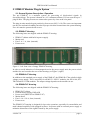
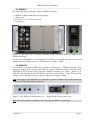
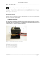
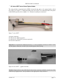
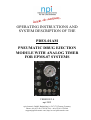
OPERATING INSTRUCTIONS AND
SYSTEM DESCRIPTION OF THE
PDES-01AM
PNEUMATIC DRUG EJECTION
MODULE WITH ANALOG TIMER
FOR EPMS-07 SYSTEMS
VERSION 2.4
npi 2015
npi electronic GmbH, Bauhofring 16, D-71732 Tamm, Germany
Phone +49 (0)7141-0730230; Fax: +49 (0)7141-9730240
[email protected]; http://www.npielectronic.com
PDES-01AM User Manual
___________________________________________________________________________
Table of Contents
1. Safety Regulations .............................................................................................................. 3
2. EPMS-07 Modular Plug-In System .................................................................................... 4
2.1. General System Description / Operation ..................................................................... 4
2.2. EPMS-07 Housing ....................................................................................................... 4
2.3. EPMS-H-07 Housing................................................................................................... 4
2.4. EPMS-E-07 Housing ................................................................................................... 4
2.5. EPMS-03 ..................................................................................................................... 5
2.6. PWR-03D .................................................................................................................... 5
2.7. System Grounding ....................................................................................................... 6
EPMS-07/EPMS-03 .................................................................................................... 6
EPMS-E-07.................................................................................................................. 6
2.8. Technical Data ............................................................................................................. 6
EPMS-07, EPMS-E-07 and EPMS-H-07 .................................................................... 6
EPMS-07 and EPMS-H-07.......................................................................................... 6
EPMS-E-07.................................................................................................................. 6
EPMS-03 ..................................................................................................................... 6
3. PDES System ...................................................................................................................... 7
3.1. System Description ...................................................................................................... 7
3.2. PDES-01AM Components .......................................................................................... 7
3.3. Description of the Front Panel ..................................................................................... 8
4. External Valves ................................................................................................................... 11
4.1. Remote Valve Plate ..................................................................................................... 11
4.2. microJECT micro Valve Pipette Holder...................................................................... 12
5. Operation ............................................................................................................................ 13
6. Literature ............................................................................................................................. 15
Microinjection into Oocytes ........................................................................................ 16
Fast Drug Application with microJECT ...................................................................... 16
7. Technical Data .................................................................................................................... 17
___________________________________________________________________________
version 2.4
page 2
PDES-01AM User Manual
___________________________________________________________________________
1. Safety Regulations
VERY IMPORTANT: Instruments and components supplied by npi electronic are NOT
intended for clinical use or medical purposes (e.g. for diagnosis or treatment of humans)
or for any other life-supporting system. npi electronic disclaims any warranties for such
purpose. Equipment supplied by npi electronic must be operated only by selected, trained
and adequately instructed personnel. For details please consult the GENERAL TERMS
OF DELIVERY AND CONDITIONS OF BUSINESS of npi electronic, D-71732 Tamm,
Germany.
1)
2)
3)
4)
5)
GENERAL: This system is designed for use in scientific laboratories and must be operated
by trained staff only. General safety regulations for operating electrical devices should be
followed.
AC MAINS CONNECTION: While working with the npi systems, always adhere to the
appropriate safety measures for handling electronic devices. Before using any device,
please read manuals and instructions carefully.
The device is to be operated only at 115/230 Volt 60/50 Hz AC. Please check for
appropriate line voltage before connecting any system to mains.
Always use a three-wire line cord and a mains power-plug with a protection contact
connected to ground (protective earth).
Before opening the cabinet, unplug the instrument.
Unplug the instrument when replacing the fuse or changing line voltage. Replace fuse only
with an appropriate specified type.
STATIC ELECTRICITY: Electronic equipment is sensitive to static discharges. Some
devices such as sensor inputs are equipped with very sensitive FET amplifiers, which can
be damaged by electrostatic charge and must therefore be handled with care. Electrostatic
discharge can be avoided by touching a grounded metal surface when changing or
adjusting sensors. Always turn power off when adding or removing modules,
connecting or disconnecting sensors, headstages or other components from the
instrument or 19” cabinet.
TEMPERATURE DRIFT / WARM-UP TIME: All analog electronic systems are sensitive
to temperature changes. Therefore, all electronic instruments containing analog circuits
should be used only in a warmed-up condition (i.e. after internal temperature has reached
steady-state values). In most cases a warm-up period of 20-30 minutes is sufficient.
HANDLING: Please protect the device from moisture, heat, radiation and corrosive
chemicals.
HIGH PRESSURE PRECAUTIONS: While working with PDES systems and components
always adhere to the appropriate safety measures for handling high pressure pneumatic systems.
Before using the PDES or any external pneumatic device please read manuals and instructions
carefully.
• Always turn off pressure source before connecting or disconnecting the PDES system.
• Any component used (tubes, fittings etc.) must be specified for the maximum possible
pressure.
• Do not use any aggressive, combustible or explosive gases. Only gases such as air, nitrogen,
carbon dioxide, helium, etc. are allowed.
• Use only dry, oil free, filtered gases (max. 5 µm filter is allowed).
• Maximum input pressure must be below 5 bar (72 psi).
___________________________________________________________________________
version 2.4
page 3
PDES-01AM User Manual
___________________________________________________________________________
2. EPMS-07 Modular Plug-In System
2.1. General System Description / Operation
The npi EPMS-07 is a modular system for processing of bioelectrical signals in
electrophysiology. The system is housed in a 19” rackmount cabinet (3U) has room for up to 7
plug-in units. The plug-in units are connected to power by a bus at the rear panel.
The plug-in units must be kept in position by four screws (M 2,5 x 10). The screws are important
not only for mechanical stability but also for proper electrical connection to the system housing.
Free area must be protected with covers.
2.2. EPMS-07 Housing
The following items are shipped with the EPMS-07 housing:
✓
✓
✓
✓
EPMS-07 cabinet with built-in power supply
Mains cord
Fuse 2 A / 1 A, slow (inserted)
Front covers
Figure 1: Left: front view of empty EPMS-07 housing.
In order to avoid induction of electromagnetic noise the power supply unit, the power switch
and the fuse are located at the rear of the housing (see Figure 2, right).
2.3. EPMS-H-07 Housing
In addition to the standard power supply of the EPMS-07, the EPMS-H-07 has a built-in high
voltage power supply. This is necessary for all MVCS / MVCC modules, the HVA-100, HVTR150 and HVC-03M modules. The output voltage depends on the modules in use.
2.4. EPMS-E-07 Housing
The following items are shipped with the EPMS-E-07 housing:
✓
✓
✓
✓
✓
✓
EPMS-E-07 cabinet
External Power supply PWR-03D
Power cord (PWR-03D to EPMS-E-07)
Mains chord
Fuse 1.6 A / 0.8 A, slow (inserted)
Front covers
The EPMS-E-07 housing is designed for low-noise operation, especially for extracellular and
multi channel amplifiers with plugged in filters. It operates with an external power supply to
minimize distortions of the signals caused by the power supply.
___________________________________________________________________________
version 2.4
page 4
PDES-01AM User Manual
___________________________________________________________________________
2.5. EPMS-03
The following items are shipped with the EPMS-07 housing:
✓
✓
✓
✓
EPMS-07 cabinet with built-in power supply
Mains cord
Fuse 034 A / 0,2 A, slow (inserted)
Front covers
Figure 2: Left: front view of EPMS-03 housing. Right: rear panel detail of EPMS-03 and
EPMS-07 housing.
In order to avoid induction of electromagnetic noise the power supply unit, the power switch
and the fuse are located at the rear of the housing (see Figure 2, right).
2.6. PWR-03D
The external power supply PWR-03D is capable of driving up to 3 EPMS-E housings. Each
housing is connected by a 6-pole cable from one of three connectors on the front panel of the
PWR-03D to the rear panel of the respective EPMS-E housing. (see Figure 3, Figure 4). A
POWER LED indicates that the PWR-03D is powered on (see Figure 3, left). Power switch,
voltage selector and fuse are located at the rear panel (see Figure 3, right).
Note: The chassis of the PWR-03D is connected to protective earth, and it provides protective
earth to the EPMS-E housing if connected.
Figure 3: Left: PWR-03D front panel view
Right: PWR-03D rear panel view.
Note: This power supply is intended to be used with npi EPMS-E systems only.
___________________________________________________________________________
version 2.4
page 5
PDES-01AM User Manual
___________________________________________________________________________
2.7. System Grounding
EPMS-07/EPMS-03
The 19" cabinet is grounded by the power cable through the ground pin of the mains connector
(= protective earth). In order to avoid ground loops the internal ground is isolated from the
protective earth. The internal ground is used on the BNC connectors or GROUND plugs of the
modules that are inserted into the EPMS-07 housing. The internal ground and mains ground (=
protective earth) can be connected by a wire using the ground plugs on the rear panel of the
instrument. It is not possible to predict whether measurements will be less or more noisy with
the internal ground and mains ground connected. We recommend that you try both
arrangements to determine the best configuration.
EPMS-E-07
The 19" cabinet is connected to the CHASSIS connector at the rear panel. It
can be connected to the SYSTEM GROUND (SIGNAL GROUND) on the rear
panel of the instrument (see Figure 4).
The chassis can be linked to PROTECTIVE EARTH by connecting it to the
PWR-03D with the supplied 6-pole cable and by interconnecting the
GROUND and PROTECTIVE EARTH connectors on the rear panel of the
PWR-03D (see Figure 3). Best performance is generally achieved without
connection of the chassis to protective earth.
Important: Always adhere to the appropriate safety measures.
Figure 4: Rear panel connectors of the EPMS-E-07
2.8. Technical Data
EPMS-07, EPMS-E-07 and EPMS-H-07
19” rackmount cabinet, for up to 7 plug-in units
Dimensions: 3U high (1U=1 3/4” = 44.45 mm), 254 mm deep
EPMS-07 and EPMS-H-07
Power supply: 115/230 V AC, 60/50 Hz, fuse 2 A / 1 A slow, 45-60 W
EPMS-E-07
External power supply (PWR-03D) 115/230 V AC, 60/50 Hz, fuse 1.6/0.8 A, slow
Dimensions of external power supply:
(W x D x H) 225 mm x 210 mm x 85 mm
EPMS-03
Power supply:
115/230 Volts AC, 60/50 Hz, fuse 0.4 A / 0.2 A slow
Maximum current supply: 500 mA
Dimensions:
3U high (1U=1 3/4” = 44.45 mm), 254 mm deep, 265 mm wide
___________________________________________________________________________
version 2.4
page 6
PDES-01AM User Manual
___________________________________________________________________________
3. PDES System
3.1. System Description
Pressure ejection is a convenient method for applying both ionic and non-ionic solutions from
micropipettes. This method is popular for two reasons. First, it can apply to almost all solutions.
Second, the amount of solution ejected can be monitored by viewing the tip of the micropipette
under a microscope.
npi PDES units are designed for pressure ejection of drugs in physiological and
pharmacological studies. PDES systems can be equipped with high pressure outputs (up to Pmax
= 4 bar / 58 psi) for drug application with fine-tipped micropipettes or with low-range pressure
output (Pmax = 0.7 bar / 10 psi) for controlled droplet application from large-tipped pipettes.
The PDES-01AM is a system with Pmax = 4 bar (58 psi). The device is designed as a module
for the npi EPMS-07 system. It comprises of one channel consisting of a precision pressure
regulator, an electronically controlled valve, (or a very fast micro valve located in the
microJECT), an analog timer and an analog pressure display. Ejection of drugs can be activated
manually or via a TTL input.
Mode of operation and timing is selected by controls at the front panel. If the internal timer is
used, the eject time is preset by a control and the time base can be selected by a toggle switch.
The operational status is indicated by a red/green LED.
The pressure connectors are also located at the front panel of the instrument. The injection
channel is equipped with an INPUT coupling where the pressure source is connected, an OUT
coupling where the injection pipette or the microJECT headstage, respectively, is connected,
and an EXHAUST coupling where a low "retain" pressure can be applied in order to avoid
capillary effects at the tip of the injection pipette (analogous to the "retaining" current used in
iontophoretic systems). This pressure must be generated by an additional pneumatic device.
Please contact npi electronic for details. Systems with microJECT are additionally equipped
with a connector for controlling the micro valve inside the microJECT.
The injection pressure is preset by a precision pressure regulator. The pressure is displayed on
an analog manometer. Additional pneumatic devices (tubes, fittings, connectors, filters etc.) are
available. Please contact npi electronic for details.
A calibration procedure allowing quantitative drug application is described by Hofmeier and
Lux (1981), (see chapter 6).
3.2. PDES-01AM Components
The following items are shipped with the PDES-01AM system:
✓ Pressure controller module for the EPMS-07 system
✓ User manual
___________________________________________________________________________
version 2.4
page 7
PDES-01AM User Manual
___________________________________________________________________________
Optional accessories:
➪
➪
➪
➪
➪
microJECT pipette holder (fast, switch time <1 ms)
Tubing
Ejection holder
Remote push button
External valve (slow, switch time >10 ms)
3.3. Description of the Front Panel
Figure 5: PDES-01AM front panel view (the numbers are related to those in the text below)
___________________________________________________________________________
version 2.4
page 8
PDES-01AM User Manual
___________________________________________________________________________
(1) Manometer
Display indicating the ejection pressure, range: 0-4 bar (0-58 psi) or 0-2.5
bar (0-36 psi).
(2) EXHAUST connector
Connector for connecting a “retain” pressure source or for EXHAUST. If no “retain”
pressure is connected, the system is exhausted as long as no pressure is applied to the
pipette.
(3) IN connector
Connector for connecting the filtered, dry and oil-free gas source. The gas source must
be filtered by a 5 µm filter element.
Important: Do not connect sources of OXYGEN or COMBUSTIBLE gases!!
Note: npi recommends an input pressure of 1 bar / 14 psi more than the maximum output
pressure.
(4) OUT connector
Connector for connecting the injection micropipette or for connecting the external
valve, e.g. microJECT. The EJECT pressure is supplied to this connector.
(5) Pressure regulator
Rotary knob for regulating the pressure of the ejection channel. The pressure is
indicated by the manometer (#1).
(6) EXTERNAL VALVE connector
Connector for the electrical connection of the external valve, e.g. microJECT.
(7) TIMING MONITOR
BNC connector providing a TTL signal that indicates the status of the regulated
injection valve (HI = valve open, LO = valve closed).
___________________________________________________________________________
version 2.4
page 9
PDES-01AM User Manual
___________________________________________________________________________
(8) REMOTE CONTROL connector
BNC connector for connecting a remote control, e.g. a pushbutton.
(9) TTL INPUT
BNC connector for connecting a TTL signal for EXTERN operation, or for using the
internal timer in TIMER operating mode (see also #10).
(10)
Operation mode switch
Switch for setting the operation mode
CONT.:
TIMER:
EXTERN:
OFF:
OFF:
The valve is continuously open
The internal timer is used. The timer can be started via a TTL HIGH signal at #9
or by pushing a pushbutton connected to #8
The valve is open as long as the input signal at #9 is high or the pushbutton is
pressed.
The module is switch OFF, the valve is closed. LED (#13) is also off.
The PDES module is turned OFF, the valve is closed. LED (#13) is also off. The
source pressure value is still shown at the manometer #1, but opening of the valve
is disabled in OFF position.
(see also chapter 4)
(11)
x10s, x1s / x0.01s / x0.01s switch
Switch to set the time base of the timer; ranges: x10 s, x1 s, x0.1 s or x0.01 s.
(12)
TIMER potentiometer
Potentiometer to set the ejection time. The total ejection time is the reading of this
potentiometer multiplied by the reading of the time base switch (#11).
Note: Due to tolerances of resistors and capacitors the time preset with the analog timer may
vary up to 20%!
___________________________________________________________________________
version 2.4
page 10
PDES-01AM User Manual
___________________________________________________________________________
(13) ON / EJECT LED
Indicates the operational status of the ejection channel.
red light:
valve is closed, i.e. OUT connector is closed and EXHAUST connector is open.
green light: valve is open, i.e. OUT connector is open and EXHAUST connector is closed.
Off (no light) valve is closed
4. External Valves
External valve(s) for the PDES system are either mounted on a remote valve plate or in the
microJECT micro valve pipette holder.
4.1. Remote Valve Plate
The valve which is controlled by the PDES is located on the remote valve plate (see Figure 6).
Tubing and cable of the external valves are connected at the front panel of the PDES system
(refer to chapter 3.3). Exhaust is usually not connected.
Figure 6: external valves on remote valve plate
1: electrical connection (black)
2: EJECT pressure tubing (red)
3: connector for ejection pipette
4: exhaust connector (optional)
___________________________________________________________________________
version 2.4
page 11
PDES-01AM User Manual
___________________________________________________________________________
4.2. microJECT micro Valve Pipette Holder
The valve which is controlled by the PDES is located in the micro valve pipette holder, called
microJECT (see Figure 7). Tubing and cable of the microJECT are connected at the front panel
of the PDES system (refer to chapter 3.3). Exhaust is usually not connected.
Figure 7: microJECT
1: pipette connector
2: connector for EJECT pressure
3: connector for EXHAUST pressure (optional)
4: electrical connection
Important: In experiments with high pressures (> 1 bar) it might be necessary to insert 2 seals
into the pipette connector in order to prevent the pipette from moving.
Figure 8: microJECT – pipette insertion
Caution: Pipettes that are not rigidly fixed in the pipette connector might be pressed out of the
connector by high pressure. Always adhere to the appropriate safety measures.
___________________________________________________________________________
version 2.4
page 12
PDES-01AM User Manual
___________________________________________________________________________
5. Operation
❏ Connect the gas source (max. 5 bar) to the INPUT connector at the front panel. The gas
source must be filtered by a 5 µm filter element.
Important: Do not connect sources of OXYGEN or COMBUSTIBLE gases!! The gas source
MUST be dry and oil free!! Please use a degreaser and filter the gas source by a 5 µm filter
element.
❏ Connect the injection pipette to the OUT connector at the front panel
or
❏ connect the microJECT pipette holder to the two microJECT connectors at the front panel
(#4 OUT and #5 EXTERNAL VALVE, Figure 5), and connect your ejection pipette to the
microJECT (#1, Figure 6).
❏ If a low "retain" pressure (analogous to the "retaining" current used in iontophoretic
systems) is required, connect the “retain” pressure source to EXHAUST at the front panel.
❏ Turn on pressure and adjust the pressure to the desired value using the pressure regulator.
❏ Connect a timing unit to the TTL INPUT connector (#9, Figure 5) at the front panel
or
connect a pushbutton to the REMOTE CONTROL connector (#8, Figure 5) at the front
panel
❏ The LED is green when no ejection occurs and red when the pressure is applied to the
pipette.
❏ Select the operation mode using the toggle switch (#11, Figure 5) at the front panel.
• In the CONT. position positive pressure is applied to the pipette continuously.
• In the EXTERN position the duration of the application is determined directly by the
duration of the TTL signal or the time the pushbutton is pressed.
• In the TIMER position the duration is preset by the timer control (#12, Figure 5) and
time base (#11, Figure 5) of the PDES. Application is started with a TTL signal
connected to TTL INPUT (#9, Figure 5) or by pressing the pushbutton connected to
#8, Figure 5. In position OFF of the timer control for pressure ejection is disabled.
• In the OFF position the PDES module is turned OFF, the valve is closed. LED (#13,
Figure 5) is also off. The source pressure value is still shown at the manometer #1,
Figure 5, but opening of the valve is disabled in OFF position.
Hint: Ejection time can be monitored by recording the signal at #7, Figure 5!
___________________________________________________________________________
version 2.4
page 13
PDES-01AM User Manual
___________________________________________________________________________
Figure 9: Operation modes of the PDES-01AM
___________________________________________________________________________
version 2.4
page 14
PDES-01AM User Manual
___________________________________________________________________________
6. Literature
❏
❏
❏
❏
❏
❏
❏
❏
❏
❏
❏
❏
❏
❏
❏
❏
Bickmeyer, U., Heine, M., Manzke, T., & Richter, D. W. (2002). Differential modulation
of Ih by 5-HT receptors in mouse CA1 hippocampal neurons. Eur.J.Neurosci. 16, 209-218.
Eggermann, E. & Feldmeyer, D. (2009). Cholinergic filtering in the recurrent excitatory
microcircuit of cortical layer 4. Proc.Natl.Acad.Sci.U.S.A. 106, 11753-11758.
Garaschuk, O., Milos, R. I., & Konnerth, A. (2006). Targeted bulk-loading of fluorescent
indicators for two-photon brain imaging in vivo. Nat.Protocols 1, 380-386.
Guzman, J. N., Hernandez, A., Galarraga, E., Tapia, D., Laville, A., Vergara, R., Aceves,
J., & Bargas, J. (2003). Dopaminergic modulation of axon collaterals interconnecting spiny
neurons of the rat striatum. J Neurosci. 23, 8931-8940.
Hahnel, C. (1992). Quantitative Microinjection, in: H. Kettenmann and R. Grantyn (eds.)
Practical Electrophysiological methods, Wiley-Liss, New York.
Hanganu, I. L. & Luhmann, H. J. (2004). Functional Nicotinic Acetylcholine Receptors on
Subplate Neurons in Neonatal Rat Somatosensory Cortex. Journal of Neurophysiology 92,
189-198.
Hofmeier, G & Lux, H. D. (1981). The time course of intracellular free calcium and related
electrical effects after injection of CaCl2 into neurons of the snail Helix pomatia, Pflügers
Arch. 391, 242-251.
Kolbaev, S. & Draguhn, A. (2008). Glutamine-induced membrane currents in cultured rat
hippocampal neurons. Eur.J Neurosci. 28, 535-545.
Lalley, P.M. (1999) Microiontophoresis and Pressure Ejection, in: U. Windhorst, and
H. Johansson (eds) Modern Techniques in Neuroscience Research, Springer, Berlin
Heidelberg, New York.
Langer, J. & Rose, C. R. (2009). Synaptically induced sodium signals in hippocampal
astrocytes in situ. J Physiol. 587, 5859-5877.
Lin, B. J., Chen, T. W., & Schild, D. (2007). Cell type-specific relationships between spiking
and [Ca2+]i in neurons of the Xenopus tadpole olfactory bulb. Journal of Physiology 582,
163-175.
Marandi, N., Konnerth, A., & Garaschuk, O. (2002). Two-photon chloride imaging in
neurons of brain slices. Pflugers Arch. 445, 357-365.
Misgeld, U. (1992). Droplet application of Agonists, in: H. Kettenmann and R. Grantyn
(eds.) Practical Electrophysiological methods. Wiley-Liss, New York
Partridge, L. D., Zeilhofer, H. U. & Swandulla, D. (1998). Combined Whole-Cell and
Single-Channel Current Measurement with Quantitative Ca2+ Injection or Fura-2
Measurement of Ca2+. In P.M. Conn (Ed.) Ion Channels Part B, Methods in Enzymology
293, Academic Press San Diego.
Ponimaskin, E., Dumuis, A., Gaven, F., Barthet, G., Heine, M., Glebov, K., Richter, D. W.,
& Oppermann, M. (2005). Palmitoylation of the 5-Hydroxytryptamine4a Receptor
Regulates Receptor Phosphorylation, Desensitization, and {beta}-Arrestin-Mediated
Endocytosis. Molecular Pharmacology 67, 1434-1443.
Qiu, J., Yao, S., Hindmarch, C., Antunes, V., Paton, J., & Murphy, D. (2007). Transcription
factor expression in the hypothalamo-neurohypophyseal system of the dehydrated rat:
upregulation of gonadotrophin inducible transcription factor 1 mRNA is mediated by cAMPdependent protein kinase A. J Neurosci. 27, 2196-2203.
___________________________________________________________________________
version 2.4
page 15
PDES-01AM User Manual
___________________________________________________________________________
❏ Stepanyan, R. & Frolenkov, G. I. (2009). Fast adaptation and Ca2+ sensitivity of the
mechanotransducer require myosin-XVa in inner but not outer cochlear hair cells. Journal
of Neuroscience 29, 4023-4034.
❏ Wolfram, V. & Juusola, M. (2004). The Impact of Rearing Conditions and Short-Term Light
Exposure on Signaling Performance in Drosophila Photoreceptors. Journal of
Neurophysiology 92, 1918-1927.
Microinjection into Oocytes
❏ Wetzel, C. H., Oles, M., Wellerdieck, C., Kuczkowiak, M., Gisselmann, G., & Hatt, H.
(1999). Specificity and sensitivity of a human olfactory receptor functionally expressed in
human embryonic kidney 293 cells and Xenopus Laevis oocytes. J.Neurosci. 19, 7426-7433.
Fast Drug Application with microJECT
❏ Courjaret, R., Troger, M., & Deitmer, J. W. (2009). Suppression of GABA input by A1
adenosine receptor activation in rat cerebellar granule cells. Neuroscience. 162, 946-958.
❏ Heck, N., Kilb, W., Reiprich, P., Kubota, H., Furukawa, T., Fukuda, A., & Luhmann, H. J.
(2007). GABA-A receptors regulate neocortical neuronal migration in vitro and in vivo.
Cereb Cortex. 17, 138-148.
___________________________________________________________________________
version 2.4
page 16
PDES-01AM User Manual
___________________________________________________________________________
7. Technical Data
Source gas:
air, nitrogen, helium etc. no aggressive, combustible or explosive gases, filtered by a 5 µm filter
element
Pressure range:
input pressure:
max. 5 bar (1 bar = 105 Pa)
pressure control range: 0-4 bar; display range 0-4 bar
or
0-2 bar; display range 0-2.5 bar
Input and output couplings:
hose fitting connect type for 4 mm (inner diameter) tubing
Status / EJECT time indicator:
red/green LED
red light:
valve is closed (in EXTERN TIMER, CONT. operation mode)
green light: valve is open
Off (no light) valve is closed
Mode selection:
four position toggle switch, OFF, EXTERN TIMER, CONT.
Minimum pressure pulsed width:
10-20 ms (dependent on tubing), 1 ms with microJECT
Analog timer:
0.001 – 0.1 s, 0.01 - 1 s, 0.1 - 10 s or 1 – 100 s with linear
control, range set by rotary switch time base selector
(x0.01 s, x0.1 s, x1 s, x10 s)
TTL INPUT:
standard BNC connector, TTL (LO = 0-2.5 V, HI = 2.5-12 V), input impedance 10 kΩ
___________________________________________________________________________
version 2.4
page 17