1
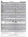
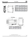
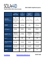
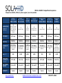
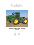
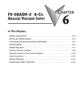
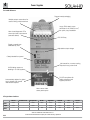
4 Power Supplies The SolaHD Difference Rugged metal packaging Multiple output connections for ease of wiring multiple devices Large, IP20-rated, screw terminals for #10 AWG/6 mm2, for quick, easy installation New visual diagnostic LEDs show input and output status (see table below) DC OK Relay Single or parallel use selectable by user Adjustable output voltage Clearly labeled front panel No internal fan, no extra cooling required in any power level UL508 listing means no derating in UL 508 systems Full CE compliance for safety, emissions and ingress protection Automatically adjusts for global Input voltages. No manual intervention required. New narrow width saves panel space LED Light Status Conditions Normal AC Power Loss AC Input Low No DC High Load Overload Hot Too Hot Input Green - Yellow Green Green Green Green Green Output Green - Green - Yellow Yellow Green - Alarm - - - Red Yellow Red Yellow Yellow 102 Visit our website at www.solahd.com or contact Technical Services at (800) 377-4384 with any questions. 4 Power Supplies SDN-C Specifications (Single Phase) Description Catalog Number SDN 5-24-100C SDN 10-24-100C SDN 20-24-100C Input Nominal Voltage 115/230 Vac -AC Range 85 - 264 Vac -DC Range 1 90 - 375 Vdc 43 - 67 Hz -Frequency 1.65 - 0.55 A 3.2 - 1.0 A -Inrush current max. Typ. < 15 A Typ.< 30 A < 40 A Efficiency (Losses ) > 90% typ. (12 W) > 90% typ. (24 W) > 92% (38 W) Nominal Current 2 3 6A/3A Active power factor correction to better than 0.92 Power Factor Correction Output 24 V (23.5~28.5 Vdc Adj.) Nominal Voltage < ±2 % overall (combination Line, load, time and temperature related changes) -Tolerance 24.5 V ± 1% Initial Voltage Setting -Ripple < 50 mVpp 4 <100 mVpp PARD (Periodic and Random Deviation) = 100 mV peak-peak max PARD > 30.5 but < 33 Vdc, auto recovery Overvoltage Protection < 35 V Power Back Immunity Nominal Current 5 A (120 W) 10 A (240 W) 1.5 x Nominal Current at near zero volts at short circuit condition -Short Circuit Current PowerBoost™ -Current Limit Parallel Operation 20 A (480 W) 1.5 × Nominal Current for 2 seconds minimum while holding voltage > 20 Vdc -Peak Current 5 Switch selectable single unit or parallel unit operation. Units will not be damaged by parallel operation (regardless of switch position setting). >20 ms (Full load, 100 Vac Input @ Tamb=+25°C) to 95% output voltage Holdup Time <150 mS from 95% to 10% rated voltage @ full load (Tamb=+25°C) Voltage Fall Time < 0.5% Line and Load Regulation General EMC: -Emissions -Immunity Approvals Temperature 6 EN61000-6-2:2001, EN61000-6-3:2001, Class B EN55011, EN55022 Radiated and Conducted including Annex. A, EN61000-3-2 EN61000-6-1:2001, EN61000-6-2:2001, EN61000-4-2 Level 4, EN61000-4-3 Level 3, EN61000-4-6 Level 3, EN61000-4-4 Level 4 input and level 3 output. EN61000-4-5 Isolation class 4, EN61000-4-11, IEC 61000-4-34 voltage dip immunity standard cULus Listed UL508, CSA C22.2 No. 107.1; UL 60950-1/CSA C22.2 No.60950-1 2nd ed, ANSI/ISA 12.12.01, CSA C22.2 UL 60950 E137632 No. 213; Class I, Div. 2, Groups A,B,C and D, T4 in a 40oC ambient; CE IEC60950-1:2005 2nd ed, EN60950-1:2006+A11:2009; CUL/CSA-C22.2 Models SDN 5-24-100C and SDN 10-24-100CNo.- 234-M90 UL60079-15/CSA C22.2 E60079-15 Class I, Zone 2 AEx nC IIC, Ex nC IIC, UL 60950 E137632 60oC ambient and ATEX EN60079-0, EN60079-15 II 3 G Ex nC IIC pending CUL/CSA-C22.2 No. 234-M90 Storage: -40oC to + 85oC, Operation -25oC to +60oC full power, with linear derating to half power from 60 to 70oC (Convection cooling, no forced air required). Operation up to 50% load permissible with sideways or front side up mounting orientation. II 3G > 550,000 hrs MTBF 7 > 450,000 hrs 5 Years Warranty General Protection/Safety Protected against continuous short -circuit, continuous overload, continuous open circuit. Protection Class 1 (IEC536), degree of protection IP20 (IEC60529) Safe low voltage: SELV (acc. IEC60950-1) Visual: 3 status LEDs (Input, Output, Alarm) Relay: N.O. contact rated 200ma/50 Vdc Status Indicators Installation Fusing -Input -Output Mounting Connections Internally fused Outputs are capable of providing high currents for short periods of time for inductive load startup or switching. Fusing may be required for wire/loads if 2x Nominal O/P current rating cannot be tolerated. Continuous current overload allows for reliable fuse tripping. Simple snap-on to DIN TS35/7.5 or TS35/15 rail system. Input: Screw terminals, connector size range: 16-10 AWG (1.5-6 mm2) for solid conductors. Output: Two terminals per output, connector size range: 16-10 AWG (1.5-6 mm2) for solid conductors. Fully enclosed metal housing with fine ventilation grid to keep out small parts. Case 15 mm in front, 25 ~ 40 mm above and below, 10 mm left and right. -Free Space H x W x D inches (mm) Weight lbs(kg) 4.85 × 1.97 × 4.36 (123 × 50 × 110) 4.85 × 2.36 × 4.36 (123 × 60 × 110) 4.85 x 3.42 x 4.98 (123 x 87 x 127) 1.10 (0.5) 1.76 (0.8) 2.6 (1.2) 1. Not UL listed for DC input. 2. Input current ratings are conservatively specified with low input, worst case efficiency and power factor. 3. Losses are heat dissipation in watts at full load, nominal input line. 4. Ripple/noise is stated as typical values when measured with a 20 MHz, bandwidth scope and 50 Ohm resistor. 5. Peak current is calculated at 24 Volt levels. 6. Contact tech support for operation at -25oC. 7. Demonstrated through extended life test. Visit our website at www.solahd.com or contact Technical Services at (800) 377-4384 with any questions. 103 4 Power Supplies SDN-C Specifications (Three Phase) Description Nominal Voltage Two - phase input -AC Range 2 -DC Range -Frequency Nominal Current 3 -Inrush current max. Efficiency (Losses 4) Power Factor Correction Turn on time Voltage Rise Time Power Back Immunity Overvoltage Protection Nominal Voltage Voltage Regulation Initial Voltage Setting -Ripple 5 PARD Catalog Number SDN 5-24-480C SDN 10-24-480C SDN 20-24-480CC SDN 40-24-480C 450 - 760 Vdc 9 N/A Input 380 - 480 Vac Yes 1 320 - 540 Vac 450 - 760 Vdc 450 - 760 Vdc 50/60 Hz 3 x 0.5 or 2 x 0.7 A 3 x 0.8 or 2 x 1.2 A 3 x 0.9 or 2 x 1.3 A 3 x 1.6 A Negligible Negligible 93% (42 W) 94% (78 W) Active Power Factor Correction Typ. <25 A > 85% (18 W) 91.2% (23.6 W) Power factor correction to meet EN61000-3-2 Class A Output Typ. 1s <100 ms full resistive load (Tamb =+25°C ) ca. 5-20 ms <35 V >30.5 but <33 Vdc auto recovery 24 V (24 - 28 Vdc Adjustable) < ±2 % overall 24.5 V ± 1% <100 mVpp PARD = 200 mV peak-peak max 20 A (480 W) (constant power, 40 A (960 W) not constant current) 6 6A, 2×Nominal Current <2sec 12A, 2×Nominal Current <2sec 1.5×Nominal Current for 4 sec minimum while holding voltage > 20Vdc -Peak Current PowerBoost™ -Current Limit typ. 12 W/oC typ. 24 W/oC typ. 48 W/oC typ. 6 W/oC Derating >20 ms >15 ms Holdup Time <50 ms from 95% to 10% rated voltage @ full load (Tamb=+25°C) <150 ms from 95% to 10% rated voltage @ full load (Tamb=+25°C) Voltage Fall Time Single or Parallel operation selectable via front switch. For redundant SDN 40 uses active paralelling Parallel Operation 7 operation, use of external diode module is preferred General Fully enclosed metal housing with fine ventilation grid to keep out small parts. Case 70mm above and below or Min. Required 25mm above and below or 25mm above and below or 70mm above and below, 15mm in 25mm in front and 25mm left & 15mm in front 10mm in front front, 25mm left & right Free Space right 4.85 × 1.97 × 4.36 (123 × 50 × 111) 4.85 × 2.36 × 4.36 (123 × 60 × 111) 4.85 x 3.35 x 4.68 (123 x 85 x 119) 4.85 x 7.09 x 4.66 (123 x 180 x 119) H×W×D inches (mm) 1.15 (.52) 1.54 (0.7) 2.86 (1.3) 5.28 (2.4) Weight lbs (kg) EN61000-6-3:2001, Class B EN55011, EN55022 Radiated and Conducted including Annex. A, EN61000-3-2 EMC: -Emissions EN61000-6-1:2001, EN61000-6-2:2001, EN61000-4-2 Level 4, EN61000-4-3 Level 3, EN61000-4-6 Level 3, EN61000-4-4 Level 4 input and level -Immunity 3 output. EN61000-4-5 Isolation class 4, EN61000-4-11, Semi F47 sag immunity. cULus Listed UL508, CSA C22.2 No. 107.1; UL 60950-1/CSA C22.2 No.60950-1 2nd ed; CE IEC60950-1:2005 2nd ed, UL 60950 E137632 EN60950-1:2006+A11:2009; SDN 20-24-480C and SDN 40-24-480C - UL 60950 ANSI/ISA 12.12.01, CSA C22.2 No. 213; Class I, Div. 2, Groups CUL/CSA-C22.2 o No. 234-M90 E137632 A,B,C and D, T4 in 60 C ambient; SDN 5-24-480C and SDN 10-24-480C - UL 60950 UL 60079-15/CSA C22.2 E60079-15 Class I, Zone 2 AEx nA Approvals CUL/CSA-C22.2 E137632 IIC, Ex nA IIC, T4 in 60oC ambient; ATEX: EN60079-0, EN60079-15 II 3No.G234-M90 Ex nC IIC Gc, T4 in 60oC ambient, DEMKO 11 ATEX 1057365U and CUL/CSA-C22.2 No. 234-M90 10 DEMKO 11 ATEX 1105449U Storage : -40 to + 85oC, Operation -25 to +60oC full power, with linear derating to half power from 60 to 70oC (Convection cooling, no forced air Temperature required). Operation up to 50% load permissible with sideways or front side up mounting orientation. < 90% RH, noncondensing; IEC 60068-2-2, 68-2-3 Humidity 0 to 3000 meters (0 to 10,000 feet) Altitude 2.5(g) RMS, 10-2000 Hz (random); three axes for 20 minutes each - IEC 60068-2-6 Vibration 3(g) peak, three axes, 11mseconds for each axis - IEC 60068-2-27 Shock 5 Years Warranty >500,000 hrs MTBF (Nominal voltage, full load, Tamb = 25oC) MTBF Protected against short -circuit, overload, open circuit. Protection class 1 (IEC536), degree of protection IP20 (IEC 529) General Protection/Safety Safe low voltage: SELV (acc. EN60950) LED Alarm, Output shutdown with automatic restart Over-temperature protection Visual: 3 status LEDs (Input, Output, Alarm) Relay: SSR or dry relay contact, signal active when Vout = 18.5 Vdc = +/-5% Status Indicators Installation Externally fused Fusing: -Input Not fused. Output is capable of providing high currents (PowerBoost) for motor load startup. -Output Simple snap-on to DIN TS35/7.5 or TS35/15 rail system. Mounting Unit should handle normal shock and vibration of industrial use and transportation without falling off the rail. Input: screw terminals, Wiring for the connector will be Ground on the left (when looking at the front of the unit), connector size range: 16-10AWG (1.5-6mm2) for solid conductors. Output: connector size range, wire gauge 6-7 AWG for SDN40; Connections 8 all other models: 16-10AWG (1.5-6mm2) for solid conductors. Nominal Current PARD = 100 mV peak-peak max 5 A (120 W) 10 A (240 W) II 3G 1. SDN 20 will operate at 75% load; SDN 40 will operate at 50% load under loss of 1 phase; SDN 5 and SDN 10 will operate with single phase input power at 100% of load. Unit will shut down if thermal threshold is exceeded under this condition. 2. Unit passed input voltage overstress test at 600 Vac without failure. 3. Input current ratings are specified with low input, line conditions, worst case efficiency values and power factor spikes. Input current at nominal input settings will typically be half these values. 4. Losses are heat dissipation in watts at full load, nominal line. 5. Ripple/noise is stated as typical values when measured with a 20 MHZ, bandwidth scope and 50 Ohm resistor. 104 6. SDN 20 and 40 unit will go to HICCUP mode. SDN 5 and 10 will maintain min 4 secs to deliver 150% load then drops to almost zero Vout. The output voltage will immediately drop to almost zero when load rises above 150%. 7. All models except the 40amp unit are capable of parallel operation by use of a jumper pin, accessible by the end user. 40 amp unit will have active current sharing signal. 8. SDN 40-24-480C only = Output signaling terminal block features (Shut down, Power Good, Current Monitor, Current Balance, signal GND). 9. 70% maximum rated load. 10. Additional Installation requirements apply when used in hazardous locations. (refer to user manual) Visit our website at www.solahd.com or contact Technical Services at (800) 377-4384 with any questions. 4 Power Supplies SDN-C Series Dimensions D W Dimensions - inches (mm) Catalog Number + + - - OK 24 VDC / 2.5 A OK NEC Class 2 Power Supply 24-28 V H W D SDN 5-24-100C 4.85 (123) 1.97 (50) 4.36 (111) SDN 10-24-100C 4.85 (123) 2.36 (60) 4.36 (111) SDN 20-24-100C 4.85 (123) 3.42 (87) 4.98 (127) SDN 5-24-480C 4.85 (123) 1.97 (50) 4.36 (111) SDN 10-24-480C 4.85 (123) 2.36 (60) 4.36 (111) SDN 20-24-480CC 4.85 (123) 3.35 (85) 4.68 (119) Single Parallel H S O LA Power Supply SDN 2.5-24-100P SDN5-24-100C C U L ���� ���� �� ���� US LISTED 115/230 VAC 1.3-0.7 A 50/60 HZ N L Catalog Number SDN 40-24-480C Dimensions - inches (mm) H W D 4.85 (123) 7.09 (180) 4.66 (118) Visit our website at www.solahd.com or contact Technical Services at (800) 377-4384 with any questions. 105 4 Power Supplies SDN-C Series Mounting (cont.) Chassis Mounting Dimensions Instead of snapping a SolaHD SDN™ unit on the DIN Rail, you can also attach it using the screw mounting set SDN-PMBRK2. This set consists of two metal brackets, which replace the existing two aluminum profiles. SDN-C Series Mounting Detachment from DIN Rail: DIN Rail Mounting Snap on the DIN Rail: 1.Tilt unit slightly backwards 2.Put it onto the DIN Rail 3. Push downwards until stopped 4. Push at the lower front edge to lock 5. Shake the unit slightly to ensure that the retainer has locked Alternative Panel Mount: Using the optional SDN-PMBRK2 accessory, the unit can be screw mounted to a panel. 106 Visit our website at www.solahd.com or contact Technical Services at (800) 377-4384 with any questions. Product Comparison Sheet SDN 5-24-480C to SDN 5-24-480 The Next Generation of SDN Series Power Supplies SDN 5-24-480C SolaHD is proud to introduce the new SDN 5-24-480C power supplies, the next generation of our popular SDN5-24-480. The new product has a significantly enhanced performance with a full 32% smaller width along the DIN rail! Every effort has been made to ensure compatibility between generations. Still, we realize that even small differences can sometimes have unforeseen impact, so we have created this document to highlight all of these differences. Specification SDN 5-24-480C SDN 5-24-480 1 phase or 3-phase 380 - 480 Vac 320-540 Vac 450-760 Vdc 50/60 Hz 3 x 0.5 or 2 x 0.7 A Typ. < 25 A > 85% (18 W) Power factor Correction to meet EN61000-3-2 Class A Similar: 1 phase or 3-phase 380 - 480 Vac 340-576 Vac 450-820 Vdc 50/60 Hz 0.5 A Typ. <18 A >90% (12 W) Nominal Voltage 24 V (24-28 VDC Adj.) 24 V (22.5 - 28.5 VDC Adj.) Initial voltage setting 24.5 V ± 1% SAME Input Nominal Voltage AC Range DC Range Frequency Nominal Current Inrush Current Max Efficiency (Losses) Power Factor Correction SAME Output < 2 % overall (combination Line, load, time and temperature related changes) < 0.5% < 0.5% SAME SAME > 30.5 but < 33 Vdc, auto recovery SAME < 35 V SAME < 1% SAME < 50 mVpp SAME Nominal Current 5 A (120 W) SAME Peak Current 6A, 2 × Nominal Current <2sec SAME Current Limit PowerBoost ™ Fold Forward (Current rises, voltage drops to maintain constant power during overload up to max peak current) Tolerance Line regulation Load regulation Over voltage protection Power Back Immunity Time & temperature drift Ripple 2011 Emerson Industrial Automation SAME EGS Electrical Group, LLC www.solahd.com Page 1 of 3 Product Comparison Sheet SDN 5-24-480C to SDN 5-24-480 Holdup Time >20ms (Full load, 380Vac Input @ T ambient +25°C) to 95% output Voltage > 16 ms at Full load (+25°C) Voltage fall time < 150ms from 95% to 10% rated voltage @ full load (T ambient =+25°C) SAME Turn on time Parallel Operation <1000mS after AC is applied to input at full resistive load (Tambient =+25°C) Single or Parallel operation selectable via front switch. For redundant operation, use of external diode module is preferred. SAME SAME General Case Fully enclosed metal housing with fine ventilation grid to keep out small parts. SAME Max. Required Free Space 25 mm above and below or 15 mm in front SAME H×W×D inches (mm) 4.85 x 1.97 x 4.36 (123.3 x 50.0 x 110.8) 4.88 x 2.91 x 4.55 (124 x 73 x 116) Weight 1.15 lb (520 g) 1.7 lbs. (730 g) Emissions Immunity Approvals Temperature Humidity Altitude Vibration EN61000-6-3:2001, Class B EN55011, SAME EN55022 Radiated and Conducted including Annex. A, EN61000-3-2 EN61000-6-1:2001, EN61000-6-2:2001, EN61000-4-2 Level 4, EN61000-4-3 Level 3, EN61000-4-6 Level 3, EN61000-4-4 Level 4 input and Level 3 output, EN61000-4-5 SAME Isolation Class 4, EN61000-4-11, SEMI F47 Sag Immunity, EN61000-4-8, EN61000-4-34, Transient protection according to VDE 0160/W2 over entire load range cULus Listed: UL 508, CSA C22.2 No. 107.1; : UL 60950-1/CSA C22.2 60950-1 2nd edition, UL 60079-15 and CAN/CSA-E60079-15, Class I, Zone 2, AEx nC IIC Gc, Ex nC IIC U SAME hazardous locations; CE: IEC60950-1:2005 2nd edition, EN60950-1:2006+A11:2009; ATEX: II 3 G Ex nC IIC Gc, DEMKO 11 ATEX 1057365U; EN60079-0:2009, EN6007915:2010 Storage : -40 to + 85 deg C, Operation -25 to Storage : -25 to + 85 deg C, Operation -10 to +60 deg C full power, with linear derating to +60 deg C full power, with linear derating to half power from 60 to 70 deg C (Convection half power from 60 to 70 deg C (Convection cooling, no forced air required). Operation up cooling, no forced air required). Operation up to 50% load permissible with sideways or front to 50% load permissible with sideways or front side up mounting orientation. side up mounting orientation. < 90% RH, non-condensing; IEC 68-2-2, 68-2SAME 3 0 to 3000 meters (0 to 10,000 feet) SAME 2.5(g) RMS, 10-2000 Hz (random); three axes for 20 minutes each - IEC 60068-2-6 2011 Emerson Industrial Automation EGS Electrical Group, LLC www.solahd.com SAME Page 2 of 3 Product Comparison Sheet SDN 5-24-480C to SDN 5-24-480 Shock Warranty MTBF General Protection/Safety Status Indicators Visual -Relay 3(g) peak, three axes, 11mseconds for each axis - IEC 60068-2-27 5 Years >500,000 hrs DMTBF (Nominal voltage, full load, T ambient = 25 degrees C Protected against short -circuit, overload, open circuit. Protection class 1 (IEC536), degree of protection IP20 (IEC 529) Safe low voltage: SELV (acc. EN60950) 3 status LEDs: Green LED when input voltage is in range and green LED on when V out = 18.5V +/-5%. Red alarm LED SSR or dry relay contact, signal active when Vout = 18.5Vdc = +/-5% SAME SAME No DMTBF figure, only calculated MTBF SAME Green LED on when Vout = 18V or greater SAME Installation Input Fusing Externally fused. Internally Fused Output Fusing Not fused. Output is capable of providing high currents (PowerBoost) for motor load startup. SAME Mounting Connections Simple snap-on to DIN TS35/7.5 or TS35/15 rail system. Unit should handle normal shock and vibration of industrial use and transportation without falling off the rail. Input: screw terminals, wiring for the connector will be Ground on the left (when looking at the front of the unit), connector size range: 16-10 AWG (1.52 6 mm ) for solid conductors. Output: connector size range, wire gauge 162 10 AWG (1.5-6 mm ) for solid conductors. The connector color will be either gray or off-white. 2011 Emerson Industrial Automation EGS Electrical Group, LLC www.solahd.com SAME SAME SAME Page 3 of 3 SDN 5-24-480C Competitive Comparison Comparison with 5A, 24Vdc, 3-phase slim models SolaHD SDN 5-24-480C DIAGNOSTICS (number of conditions) EFFICIENCY Mains Frequency RELIABILITY (MTBF) Size (cm3 ) Width along the DIN rail inch (mm) FULL POWER AMBIENT WARRANTY www.solahd.com PULS (Two-Phase Input) CT5.241 8 (Normal, AC Power Loss, AC Input Low, No DC, High Load, Overload, Hot, Too Hot) 2 (DC ON, DC OFF) Phoenix Contact QUINTPS/3AC/24DC/5 4 (IOUT<IN , IOUT>IN, VOUT<0.9xVN, VOUT>0.9xVN) AB/Rockwell (Two-Phase Input) 1606-XLE120E-2 2 (DC ON, DC OFF) >85% typ. >90.4% typ. >89% 90 % typ. 50-60 Hz 50-60 Hz 50-60 Hz 50-60 Hz >500,000 hrs >1,173 khrs > 500,000 hrs 1,173,000 hrs (Nominal Voltage, Full load, 25°C Ambient) (40°C, SN 29500) in acc. with IEC 61709 (SN29500) SN 29500, IEC 61709 (24 V, 5 A and 40°C) 682 580 650 580 1.97 (50) 1.57 (40) 1.57 (40) 1.57 (40) -25 to 60°C -25 to 60°C -25 to 60°C -25 to 60°C 5 years 3 years 5 years 1 year [email protected] 800-377-4384 SDN 5-24-480C Competitive Comparison Comparison with 5A, 24Vdc, 3-phase regular (non-slim) models SolaHD (Compact) SDN 5-24-480C DIAGNOSTICS (number of conditions) SolaHD (Non-Compact) SDN 5-24-480 PULS SL5.300 Lambda DPP-120-24-3 Phoenix Contact TRIOPS/3AC/24DC/5 Mean well (Two-Phase Input) DRH-120-24 AB/Rockwell 1606XL120E-3 8 (Normal, AC Power Loss, AC Input Low, No DC, High Load, Overload, Hot, Too Hot) 2 2 3 2 2 2 (DC ON, DC OFF) (DC ON, DC OFF) (DC ON, DC OFF, DC Output Low) (DC ON, DC OFF) (DC ON, DC OFF) (DC ON, DC OFF) >85% typ. >90% typ. 89% typ. 84-93% >89% 85% typ. 89% typ. 50-60 Hz 50-60 Hz 50-60 Hz 50-60 Hz 50-60 Hz 50-60 Hz 50-60 Hz >500,000hrs >1,110,000hrs 410,000hrs (MIL STD 217F, 30°C Ambient) (24V/5A, 3 AC 400V, 40°C ambient) 527,000hrs (Bellcore Issue 6 @ 40°C, GB) > 500,000 hrs (in acc. with IEC 61709 SN29500) 178.7 khrs (MIL-HDBK-217F, 25°C) acc. to Siemensnorm 29500 (24V/5A, 400Vac, 40°C) 682 1,050 1,059 1,093 598 820 1,059 Width along the DIN rail inch (mm) 1.97 (50) 2.91 (73) 2.91 (73) 2.92 (74.17) 1.57 (40) 2.58 (65.5) 2.87 (73) FULL POWER AMBIENT -25 to 60°C -10 to 60°C -10 to 60°C -25 to 60°C -25 to 55°C -20 to 60°C -25 to 60°C 5 years 5 years 3 years 2 years 5 years 3 years 1 year EFFICIENCY Mains Frequency RELIABILITY (MTBF) Size (cm3 ) WARRANTY (Nominal Voltage, Full load, 25°C Ambient) www.solahd.com [email protected] 410,000 hrs 800-377-4384 Product Comparison Sheet SDN 10-24-480C to SDN 10-24-480 The Next Generation of SDN Series Power Supplies SDN 10-24-480C SolaHD is proud to introduce the new SDN 10-24-480C power supplies, the next generation of our popular SDN 10-24-480. The new product has a significantly enhanced performance with a full 32% smaller width along the DIN rail! Every effort has been made to ensure compatibility between generations. Still, we realize that even small differences can sometimes have unforeseen impact, so we have created this document to highlight all of these differences. Specification SDN 10-24-480C SDN 10-24-480 1 phase or 3-phase 380 - 480 Vac 320-540 Vac 450-760 Vdc 50/60 Hz 3 x 0.8 or 2 x 1.2 A Typ. < 25 A > 91.2% (23.6 W) Power factor Correction to meet EN61000-3-2 Class A Similar: 1 phase or 3-phase 380 - 480 Vac 340-576 Vac 450-820 Vdc 50/60 Hz 0.8 A Typ. <18 A >90% (48 W) Nominal Voltage 24 V (24-28 VDC Adj.) 24 V (22.5 - 28.5 VDC Adj.) Initial voltage setting 24.5 V ± 1% SAME Input Nominal Voltage AC Range DC Range Frequency Nominal Current Inrush Current Max Efficiency (Losses) Power Factor Correction SAME Output < 2 % overall (combination Line, load, time and temperature related changes) < 0.5% < 0.5% SAME SAME > 30.5 but < 33 Vdc, auto recovery SAME < 35 V SAME < 1% SAME < 50 mVpp SAME Nominal Current 10 A (240 W) SAME Peak Current 12A, 2 × Nominal Current <2sec SAME Current Limit PowerBoost ™ Fold Forward (Current rises, voltage drops to maintain constant power during overload up to max peak current) Tolerance Line regulation Load regulation Over voltage protection Power Back Immunity Time & temperature drift Ripple 2011 Emerson Industrial Automation SAME EGS Electrical Group, LLC www.solahd.com Page 1 of 3 Product Comparison Sheet SDN 10-24-480C to SDN 10-24-480 Holdup Time >20ms (Full load, 380Vac Input @ T ambient +25°C) to 95% output Voltage > 24 ms at Full load (+25°C) Voltage fall time < 150ms from 95% to 10% rated voltage @ full load (T ambient =+25°C) SAME Turn on time Parallel Operation <1000mS after AC is applied to input at full resistive load (Tambient =+25°C) Single or Parallel operation selectable via front switch. For redundant operation, use of external diode module is preferred. SAME SAME General Case Fully enclosed metal housing with fine ventilation grid to keep out small parts. SAME Max. Required Free Space 25 mm above and below or 10 mm in front 25 mm above and below or 15 mm in front H×W×D inches (mm) 4.85 x 2.36 x 4.36 (123.3 x 60.0 x 110.8) 4.88 x 3.5 x 4.55 (124 x 89 x 116) Weight 1.54 lb (700 g) 2.16 lbs. (980 g) Emissions Immunity Approvals Temperature Humidity Altitude Vibration EN61000-6-3:2001, Class B EN55011, SAME EN55022 Radiated and Conducted including Annex. A, EN61000-3-2 EN61000-6-1:2001, EN61000-6-2:2001, EN61000-4-2 Level 4, EN61000-4-3 Level 3, EN61000-4-6 Level 3, EN61000-4-4 Level 4 input and Level 3 output, EN61000-4-5 SAME Isolation Class 4, EN61000-4-11, SEMI F47 Sag Immunity, EN61000-4-8, EN61000-4-34, Transient protection according to VDE 0160/W2 over entire load range cULus Listed: UL 508, CSA C22.2 No. 107.1; : UL 60950-1/CSA C22.2 60950-1 2nd edition, UL 60079-15 and CAN/CSA-E60079-15, Class I, Zone 2, AEx nC IIC Gc, Ex nC IIC U SAME hazardous locations; CE: IEC60950-1:2005 2nd edition, EN60950-1:2006+A11:2009; ATEX: II 3 G Ex nC IIC Gc, DEMKO 11 ATEX 1057365U; EN60079-0:2009, EN6007915:2010 Storage : -40 to + 85 deg C, Operation -25 to Storage : -25 to + 85 deg C, Operation -10 to +60 deg C full power, with linear derating to +60 deg C full power, with linear derating to half power from 60 to 70 deg C (Convection half power from 60 to 70 deg C (Convection cooling, no forced air required). Operation up cooling, no forced air required). Operation up to 50% load permissible with sideways or front to 50% load permissible with sideways or front side up mounting orientation. side up mounting orientation. < 90% RH, noncondensing; IEC 68-2-2, 68-2-3 SAME 0 to 3000 meters (0 to 10,000 feet) SAME 2.5(g) RMS, 10-2000 Hz (random); three axes for 20 minutes each - IEC 60068-2-6 2011 Emerson Industrial Automation EGS Electrical Group, LLC www.solahd.com SAME Page 2 of 3 Product Comparison Sheet SDN 10-24-480C to SDN 10-24-480 Shock Warranty MTBF General Protection/Safety Status Indicators Visual -Relay 3(g) peak, three axes, 11mseconds for each axis - IEC 60068-2-27 5 Years >500,000 hrs DMTBF (Nominal voltage, full load, T ambient = 25 degrees C Protected against short -circuit, overload, open circuit. Protection class 1 (IEC536), degree of protection IP20 (IEC 529) Safe low voltage: SELV (acc. EN60950) 3 status LEDs: Green LED when input voltage is in range and green LED on when V out = 18.5V +/-5%. Red alarm LED SSR or dry relay contact, signal active when Vout = 18.5Vdc = +/-5% SAME SAME No DMTBF figure, only calculated MTBF SAME Green LED on when Vout = 18V or greater SAME Installation Input Fusing Externally fused. Internally Fused Output Fusing Not fused. Output is capable of providing high currents (PowerBoost) for motor load startup. SAME Mounting Connections Simple snap-on to DIN TS35/7.5 or TS35/15 rail system. Unit should handle normal shock and vibration of industrial use and transportation without falling off the rail. Input: screw terminals, wiring for the connector will be Ground on the left (when looking at the front of the unit), connector size range: 16-10 AWG (1.52 6 mm ) for solid conductors. Output: connector size range, wire gauge 162 10 AWG (1.5-6 mm ) for solid conductors. The connector color will be either gray or off-white. 2011 Emerson Industrial Automation EGS Electrical Group, LLC www.solahd.com SAME SAME SAME Page 3 of 3 SDN 10-24-480C Competitive Comparison Comparison with 10A, 24Vdc, 3-phase slim models SolaHD SDN 10-24-480C DIAGNOSTICS (number of conditions) EFFICIENCY Mains Frequency RELIABILITY (MTBF) Size (cm3 ) Width along the DIN rail inch (mm) FULL POWER AMBIENT WARRANTY www.solahd.com PULS CT10.241 Phoenix Contact QUINTPS/3AC/24DC/10 2 (IOUT<IN , IOUT>IN, 8 (Normal, AC Power Loss, AC Input Low, No DC, High Load, Overload, Hot, Too Hot) (DC ON, DC OFF) 4 VOUT<0.9xVN, AB/Rockwell 1606-XLE240E-3 2 (DC ON, DC OFF) VOUT>0.9xVN) >91.2% typ. >92.8% typ. >93% typ. 92.9% typ. 50-60Hz 50-60Hz 50-60Hz 50-60Hz >500,000 hrs >975,000 hrs > 500,000 hrs > 700,000 hrs (Nominal Voltage, Full load, 25°C Ambient) (SN 29500, IEC 61709, 40°C Ambient) in acc. with IEC 61709 (SN29500) (Siemens norm SN29500 @ full load current, 40°C Ambient) 819 899 975 899 2.36 (60) 2.44 (62) 2.36 (60) 2.44 (62) -25 to 60°C -25 to 60°C -25 to 60°C -25 to 60°C 5 years 3 years 5 years 1 year [email protected] 800-377-4384 SDN 10-24-480C Competitive Comparison Comparison with 10A, 24Vdc, 3-phase regular (non-slim) models SolaHD (Compact) SDN 10-24-480C DIAGNOSTICS (number of conditions) SolaHD (Non-Compact) SDN 10-24-480 PULS SL10.300 Lambda DPP-240-24-3 Phoenix Contact TRIOPS/3AC/24DC/10 Mean well DRT-240-24 3 2 2 AB/Rockwell 1606XL240E-3 8 (Normal, AC Power Loss, AC Input Low, No DC, High Load, Overload, Hot, Too Hot) 2 2 3 (DC ON, DC OFF) (DC ON, DC OFF) (DC ON, DC OFF, DC Output Low) (DC ON, DC OFF) (DC ON, DC OFF) (DC ON, DC OFF, Overload) >91.2% typ. >90% typ. 91.2% typ. 90% >89% 89% typ. 91.2% typ. 50-60Hz 50-60Hz 50-60 Hz 50-60Hz 50-60 Hz 50-60Hz 50-60Hz >500,000 hrs (Nominal Voltage, Full load, 25°C Ambient) >940,000 hrs 543,000 hrs (MIL STD 217F, 30°C Ambient) (24V/10A, 3 AC 400V, 40°C Ambient) 488,000 (Bellcore Issue 6 @ 40°C, GB) > 500,000 hrs in acc. with IEC 61709 (SN29500) 114.6 khrs (MIL-HDBK217F, 25°C) acc. to Siemensnorm 29500 (24V/10A, 400Vac, 40°C) 819 1,280 1,291 1,309 1,189.5 1,571 1,291 Width along the DIN rail inch (mm) 2.36 (60) 3.50 (89) 3.50 (89) 3.50 (89) 2.36 (60) 4.94 (125.5) 3.50 (89) FULL POWER AMBIENT -25 to 60°C -10 to 60°C 0 to 60°C -25 to 60°C -25 to 55°C -20 to 60°C -25 to 60°C 5 years 5 years 3 years 2 years 5 years 3 years 1 year EFFICIENCY Mains Frequency RELIABILITY (MTBF) Size (cm3 ) WARRANTY www.solahd.com [email protected] 543,000 hrs 800-377-4384