1
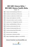
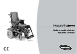
9
Seating systems
9.1
Standard and Kontur Seats
9.1.1
Adjusting the seat tilt
Kontur Seat
Manual adjustment:
• Manual adjustment:
• Loosen the knurled nut (1) and screw downwards.
• Turn the threaded adjustment sleeve (2) counterclockwise = lift the front
edge of the seat.
• Turn the threaded adjustment sleeve (2) clockwise = lower the front edge
of the seat.
• Re-tighten the knurled nut (1).
53
Electric adjustment:
The seat tilt of the wheelchair with electric actuator is adjusted using the ACS-Joystick Box. The adjustment
is infinitely variable, and can be selected in the range between -1° and +18°. If your wheelchair is equipped
with an electric lifter, then the adjustment range is between 0° and 9°.
• Switch the Joystick Box to Driving Mode "0” using the "Driving Mode Down” Button (see the description
of the Joystick Box). The Driving Mode Display automatically switches to a symbol of the seat.
•
•
•
54
By moving the Joystick to the right or left, the different options are
displayed one after the other as symbols. Scroll through options until you
the symbol depicted at right.
You can now individually adjust the seat tilt by moving the Joystick
forwards or backwards.
Finally, switch the Joystick Box back to Driving Mode by pressing the "Driving Mode Up” Button.
9.1.2
Backrest adjustment
Manual adjustment:
• The lever for adjusting the backrest can be located either on the right or left
side behind one of the clamping levers for adjusting the armrest height.
• Pull lever upwards.
• Press backrest backwards using your own weight.
• When the backrest is in the desired position, release the lever.
55
Adjustment by metal plate with holes (available as an option for
Standard Seats)
• The angle of the backrest is determined by the metal plate with screwholes, which attaches the backrest to the frame.
• The angle can be changed by selecting different combinations of holes
between 0°, 5°, 10° or 15° (see drawing).
Position of the metal
plate
•
Metal plate with holes
•
•
Remove the screws that hold the backrest frame on both sides using a 13
mm open-end spanner.
Select the correct holes for the desired angle using the drawing at right.
Re-fasten the backrest frame using the hole combination selected.
NOTE:
To make it easier to re-position the screws that hold the backrest, it may be held in place by a
second person.
56
Backrest with electric adjustment (option):
WARNING: Danger of tipping over!
• When driving, the backrest angle must never exceed 15°!
The backrest angle of the wheelchair with electric actuator is adjusted using the ACS-Joystick Box. The
adjustment is infinitely variable, and can be selected in the range between 0° and 45°.
•
Switch the Joystick Box to Driving Mode "0” using the "Driving Mode Down” Button.
The Driving Mode Display automatically switches to a symbol of the seat.
•
By moving the Joystick to the right or left, the different options are displayed one after
the other as symbols. Scroll through options until you the symbol depicted at right.
•
You can now individually adjust the angle of the backrest by moving the Joystick
forwards or backwards.
•
Finally, switch the Joystick Box back to Driving Mode by pressing the "Driving Mode
Up” Button.
57
9.1.3
Adjusting the headrest
Height adjustment:
• Loosen the clamping lever (1).
• Slide the headrest to the desired height.
• Re-tighten clamping lever (1).
Positioning the headrest:
• Loosen the clamping lever (2).
• Adjust the headrest to the desired angle.
• Re-tighten clamping lever (2).
58
9.1.4
Adjusting the height of the armrests
• Loosen the clamping lever.
• Pull the armrest upwards until the desired height is reached.
• Re-tighten clamping lever again.
9.1.5
Adjusting the height of the sideframes
• Loosen the screws using a 4 mm Allen Key.
• Adjust the sideframes to the desired position.
• Tighten the screw again.
9.1.6
Seat width adjustment:
• The clamping levers which allow adjustment of the seat width are located
under the seat.
Position of the clamping
levers
59
• Loosen the clamping lever.
• Pull the armrest frames outwards until the desired width is reached.
• Re-tighten clamping lever again.
9.1.7
Adjusting the pommel:
To position the pommel:
• Loosen the thumb screws (1 to 3)
• Adjust the pommel to the desired position.
• Re-tighten the thumb screws (1 to 3)
60
9.2
Recaro Seats
9.2.1
Recaro "N-Joy" and "Miles" (mechanically adjustable)
Backrest adjustment:
• When the hand wheel is turned forwards, the backrest is raised.
• When the hand wheel is turned backwards, the backrest is lowered.
Adjusting the height of the armrests
• Loosen one of the thumb screws depicted at right.
• Pull the armrest upwards until the desired height is reached.
• Re-tighten the thumb screw again.
61
9.2.2
Recaro Ergomed DS (electrically adjustable):
For a detailed description of the functions of the
Recaro Ergomed DS, please see the Recaro User's Manual.
By pressing the buttons, the Recaro Seat can be individually adjusted.
1. Backrest cushion 1
2. Backrest cushion 2
3. Seat height / seat tilt rear
4. Seat height / seat tilt front
5. Backrest Adjustment
62
9.3
Invacare® Ultimate and Personal Special
Seating Systems
Invacare® Special
Seating System
There are two different Invacare® Special Seating Systems, the Personal and
the Ultimate versions. Both systems have ergonomically formed back and seat
elements. In addition, the Ultimate back is equipped with inflatable side and
lumbar cushions.
9.3.1
Adjusting the seat tilt
Manual adjustment:
• Manual adjustment:
• Loosen the knurled nut (1) and screw downwards.
• Turn the threaded adjustment sleeve (2) counterclockwise = lift the front
edge of the seat.
• Turn the threaded adjustment sleeve (2) clockwise = lower the front edge
of the seat.
• Re-tighten the knurled nut (1).
Electric adjustment:
• Adjustment of the seat tilt by means of an electric actuator is described in
the ACS User's Manual.
63
9.3.2
Seat version: Personal
9.3.2.1
Adjusting the height of the back
•
•
•
64
Loosen the screws that hold both (1) retainer plates with a Phillips
Screwdriver.
Determine which holes in the backrest frame (2) and on the plates
correspond to the desired height.
Re-fasten the plates using the hole combination selected.
Retainer plate
9.3.2.2
Adjusting the backrest angle
The angle of the backrest is determined by the pins and the slots in the plates on the
backrest frame.
Plate - pins
lower slot
•
Release the securing belts (1) for the lower backrest holder (Velcro).
Lower
backrest
holder
65
•
Turn the levers (1) of both holders until the cams (2) can be pulled out of
the slots on the plates.
Lower backrest holder
•
•
•
Unhook the upper backrest support and reposition it in the desired slots.
Bring the lower backrest support into the desired position.
Turn the levers (1) of both holders until the cams (2) can be slid into the
slots on the plates.
Slide the holder in and turn until it reaches the securing belts.
Secure the lever using the securing belts.
Retainer plate
Upper backrest support
•
•
Lower backrest holder
66
9.3.3
Seat version: Ultimate
9.3.3.1
Adjusting the height of the back
•
•
•
Position of the backrest
holder
Loosen the retainer screws (1) of both upper backrest holders with a 4mm Backrest holder
Allen Key.
Adjust to the desired height.
Tighten the screws again.
67
9.3.3.2
Adjusting the backrest angle
Position of the metal
plate
The angle of the backrest is determined by the metal plate with screw-holes,
which attaches the backrest to the frame.
The angle can be changed by selecting different combinations of holes
between 0°, 5°, 10° or 15° (see drawing).
•
•
•
Remove the screws that hold the backrest frame on both sides using a 13
mm open-end spanner.
Select the correct holes for the desired angle using the drawing at right.
Re-fasten the backrest frame using the hole combination selected.
Metal plate with holes
NOTE:
To make it easier to re-position the screws that hold the backrest, it may be held in place by a
second person.
68
Fine adjustment of the backrest angle:
By turning the hand wheel, the backrest angle can be finely adjusted.
• Turn the hand wheel to the right
= increase the angle
• Turn the hand wheel to the left
= decrease the angle
Hand wheel
9.3.3.3
Position of the rubber
hand pumps
•
Adjusting the inflatable cushions
Inflate the inflatable cushions to the required size using the rubber hand
pumps.
Right and left rubber hand pumps = lateral inflatable cushions
Middle rubber hand pump
= lumbar cushion.
• Let air out of the lateral cushions using the release valves (1).
• Let air out of the lumbar cushion by using the release valve screw (2).
Letting air out
69
9.3.3.4
Removing the backrest
Upper backrest holders
• Loosen the clamps on both upper backrest holders by turning them.
Lower
latching
mechanism
70
•
Pull both lower latching mechanisms and remove backrest in an upward
direction.
Pull the levers
Refitting the backrest:
• Fit the backrest into the upper backrest holders and tighten the clamps.
• Pull the lower release mechanisms and snap the backrest into the
backrest frame.
Refitting the backrest
71