1
MELSEC iQ-R C Controller Module
User's Manual(Application)
-R12CCPU-V
SAFETY PRECAUTIONS
(Read these precautions before using this product.)
Before using this product, please read this manual and the relevant manuals carefully, and pay full attention to safety to
handle the product correctly.
In this manual, the safety precautions are classified into two levels: "
WARNING" and "
CAUTION".
WARNING
Indicates that incorrect handling may cause hazardous conditions, resulting in
death or severe injury.
CAUTION
Indicates that incorrect handling may cause hazardous conditions, resulting in
minor or moderate injury or property damage.
Under some circumstances, failure to observe the precautions given under "
CAUTION" may lead to serious
consequences.
Observe the precautions of both levels because they are important for personal and system safety.
Make sure that the end users read this manual and then keep the manual in a safe place for future reference.
[Considerations for using this manual]
● Replace the terms used in the following pages in this manual with the terms shown on the right,
respectively.
Corresponding page: SAFETY PRECAUTIONS, CONDITIONS OF USE FOR THE PRODUCT, and
COMPLIANCE WITH THE EMC AND LOW VOLTAGE DIRECTIVES
(1) "Programmable controller" "C Controller module"
(2) "Programmable controller system" "C Controller system"
● For details on a fail-safe circuit for C Controller module, refer to the following section.
Page 196 General Safety Requirements
1
[Design Precautions]
WARNING
● Configure safety circuits external to the programmable controller to ensure that the entire system
operates safely even when a fault occurs in the external power supply or the programmable controller.
Failure to do so may result in an accident due to an incorrect output or malfunction.
(1) Emergency stop circuits, protection circuits, and protective interlock circuits for conflicting
operations (such as forward/reverse rotations or upper/lower limit positioning) must be configured
external to the programmable controller.
(2) When the programmable controller detects an abnormal condition, it stops the operation and all
outputs are:
• Turned off if the overcurrent or overvoltage protection of the power supply module is activated.
• Held or turned off according to the parameter setting if the self-diagnostic function of the CPU
module detects an error such as a watchdog timer error.
(3) All outputs may be turned on if an error occurs in a part, such as an I/O control part, where the
CPU module cannot detect any error. To ensure safety operation in such a case, provide a safety
mechanism or a fail-safe circuit external to the programmable controller. For a fail-safe circuit
example, refer to "General Safety Requirements" in the MELSEC iQ-R Module Configuration
Manual.
(4) Outputs may remain on or off due to a failure of a component such as a relay and transistor in an
output circuit. Configure an external circuit for monitoring output signals that could cause a
serious accident.
● In an output circuit, when a load current exceeding the rated current or an overcurrent caused by a
load short-circuit flows for a long time, it may cause smoke and fire. To prevent this, configure an
external safety circuit, such as a fuse.
● Configure a circuit so that the programmable controller is turned on first and then the external power
supply. If the external power supply is turned on first, an accident may occur due to an incorrect output
or malfunction.
● For the operating status of each station after a communication failure, refer to manuals relevant to the
network. Incorrect output or malfunction due to a communication failure may result in an accident.
● When connecting an external device with a CPU module or intelligent function module to modify data
of a running programmable controller, configure an interlock circuit in the program to ensure that the
entire system will always operate safely. For other forms of control (such as program modification,
parameter change, forced output, or operating status change) of a running programmable controller,
read the relevant manuals carefully and ensure that the operation is safe before proceeding. Improper
operation may damage machines or cause accidents.
● Especially, when a remote programmable controller is controlled by an external device, immediate
action cannot be taken if a problem occurs in the programmable controller due to a communication
failure. To prevent this, configure an interlock circuit in the program, and determine corrective actions
to be taken between the external device and CPU module in case of a communication failure.
2
[Design Precautions]
WARNING
● Do not write any data to the "system area" and "write-protect area" of the buffer memory in the
module. Also, do not use any "use prohibited" signals as an output signal from the CPU module to
each module. Doing so may cause malfunction of the programmable controller system. For the
"system area", "write-protect area", and the "use prohibited" signals, refer to the user's manual for the
module used.
● If a communication cable is disconnected, the network may be unstable, resulting in a communication
failure of multiple stations. Configure an interlock circuit in the program to ensure that the entire
system will always operate safely even if communications fail. Incorrect output or malfunction due to a
communication failure may result in an accident.
● To maintain the safety of the programmable controller system against unauthorized access from
external devices via the network, take appropriate measures. To maintain the safety against
unauthorized access via the Internet, take measures such as installing a firewall.
[Precautions for using C Controller modules]
● In refresh parameter settings, the device Y cannot be specified for the link output (LY) refresh device
or the remote output (RY) refresh device. Therefore, C Controller module holds the device status as is
even after the module status is changed to STOP.
3
[Design Precautions]
CAUTION
● Do not install the control lines or communication cables together with the main circuit lines or power
cables. Keep a distance of 100mm or more between them. Failure to do so may result in malfunction
due to noise.
● During control of an inductive load such as a lamp, heater, or solenoid valve, a large current
(approximately ten times greater than normal) may flow when the output is turned from off to on.
Therefore, use a module that has a sufficient current rating.
● After the CPU module is powered on or is reset, the time taken to enter the RUN status varies
depending on the system configuration, parameter settings, and/or program size. Design circuits so
that the entire system will always operate safely, regardless of the time.
● Do not power off the programmable controller or do not reset the CPU module while the settings are
being written. Doing so will make the data in the flash ROM undefined. The values need to be set in
the buffer memory and written to the flash ROM again. Doing so may cause malfunction or failure of
the module.
● When changing the operating status of the CPU module from external devices (such as remote RUN/
STOP functions), select "Do Not Open in Program" for "Open Method Setting" in the module
parameters. If "Open in Program" is selected, an execution of remote STOP causes the
communication line to close. Consequently, the CPU module cannot reopen the communication line,
and the external device cannot execute the remote RUN.
4
[Installation Precautions]
WARNING
● Shut off the external power supply (all phases) used in the system before mounting or removing the
module. Failure to do so may result in electric shock or cause the module to fail or malfunction.
[Precautions for using C Controller modules]
● Do not mount C Controller module on the right end of the base unit. Attach a blank cover module
(RG60) to prevent entrance of foreign material such as dust when no module is mounted on the right
side of C Controller module.
[Installation Precautions]
CAUTION
● Use the programmable controller in an environment that meets general specifications written in Safety
Guidelines included in the base unit. Failure to do so may result in electric shock, fire, malfunction, or
damage to or deterioration of the product.
● To mount a module, place the concave part(s) located at the bottom onto the guide(s) of the base unit,
and push in the module until the hook(s) located at the top snaps into place. Incorrect interconnection
may cause malfunction, failure, or drop of the module.
● When using the programmable controller in an environment of frequent vibrations, fix the module with
a screw.
● Tighten the screws within the specified torque range. Undertightening can cause drop of the screw,
short circuit, or malfunction. Overtightening can damage the screw and/or module, resulting in drop,
short circuit, or malfunction.
● When using an extension cable, connect it to the extension cable connector of the base unit securely.
Check the connection for looseness. Poor contact may cause malfunction.
● When using an SD memory card, fully insert it into the memory card slot. Check that it is inserted
completely. Poor contact may cause malfunction.
● Securely insert an extended SRAM cassette into the cassette connector of a CPU module. After
insertion, close the cassette cover and check that the cassette is inserted completely. Poor contact
may cause malfunction.
● Do not directly touch any conductive parts and electronic components of the module, SD memory
card, extended SRAM cassette, or connector. Doing so may cause malfunction or failure of the
module.
[Wiring Precautions]
WARNING
● Shut off the external power supply (all phases) used in the system before installation and wiring.
Failure to do so may result in electric shock or cause the module to fail or malfunction.
● After installation and wiring, attach the included terminal cover to the module before turning it on for
operation. Failure to do so may result in electric shock.
5
[Wiring Precautions]
CAUTION
● Individually ground the FG and LG terminals of the programmable controller with a ground resistance
of 100 ohms or less. Failure to do so may result in electric shock or malfunction.
● Use applicable solderless terminals and tighten them within the specified torque range. If any spade
solderless terminal is used, it may be disconnected when the terminal screw comes loose, resulting in
failure.
● Check the rated voltage and signal layout before wiring to the module, and connect the cables
correctly. Connecting a power supply with a different voltage rating or incorrect wiring may cause fire
or failure.
● Connectors for external devices must be crimped or pressed with the tool specified by the
manufacturer, or must be correctly soldered. Incomplete connections may cause short circuit, fire, or
malfunction.
● Securely connect the connector to the module. Poor contact may cause malfunction.
● Do not install the control lines or communication cables together with the main circuit lines or power
cables. Keep a distance of 100mm or more between them. Failure to do so may result in malfunction
due to noise.
● Place the cables in a duct or clamp them. If not, dangling cable may swing or inadvertently be pulled,
resulting in damage to the module or cables or malfunction due to poor contact. Do not clamp the
extension cables with the jacket stripped.
● Check the interface type and correctly connect the cable. Incorrect wiring (connecting the cable to an
incorrect interface) may cause failure of the module and external device.
● Tighten the terminal screws or connector screws within the specified torque range. Undertightening
can cause drop of the screw, short circuit, fire, or malfunction. Overtightening can damage the screw
and/or module, resulting in drop, short circuit, fire, or malfunction.
● When disconnecting the cable from the module, do not pull the cable by the cable part. For the cable
with connector, hold the connector part of the cable. For the cable connected to the terminal block,
loosen the terminal screw. Pulling the cable connected to the module may result in malfunction or
damage to the module or cable.
● Prevent foreign matter such as dust or wire chips from entering the module. Such foreign matter can
cause a fire, failure, or malfunction.
● A protective film is attached to the top of the module to prevent foreign matter, such as wire chips,
from entering the module during wiring. Do not remove the film during wiring. Remove it for heat
dissipation before system operation.
6
[Wiring Precautions]
CAUTION
● Programmable controllers must be installed in control panels. Connect the main power supply to the
power supply module in the control panel through a relay terminal block. Wiring and replacement of a
power supply module must be performed by qualified maintenance personnel with knowledge of
protection against electric shock. For wiring, refer to the MELSEC iQ-R Module Configuration Manual.
● For Ethernet cables to be used in the system, select the ones that meet the specifications in the user's
manual for the module used. If not, normal data transmission is not guaranteed.
[Startup and Maintenance Precautions]
WARNING
● Do not touch any terminal while power is on. Doing so will cause electric shock or malfunction.
● Correctly connect the battery connector. Do not charge, disassemble, heat, short-circuit, solder, or
throw the battery into the fire. Also, do not expose it to liquid or strong shock. Doing so will cause the
battery to produce heat, explode, ignite, or leak, resulting in injury or fire.
● Shut off the external power supply (all phases) used in the system before cleaning the module or
retightening the terminal screws, connector screws, or module fixing screws. Failure to do so may
result in electric shock.
7
[Startup and Maintenance Precautions]
CAUTION
● When connecting an external device with a CPU module or intelligent function module to modify data
of a running programmable controller, configure an interlock circuit in the program to ensure that the
entire system will always operate safely. For other forms of control (such as program modification,
parameter change, forced output, or operating status change) of a running programmable controller,
read the relevant manuals carefully and ensure that the operation is safe before proceeding. Improper
operation may damage machines or cause accidents.
● Especially, when a remote programmable controller is controlled by an external device, immediate
action cannot be taken if a problem occurs in the programmable controller due to a communication
failure. To prevent this, configure an interlock circuit in the program, and determine corrective actions
to be taken between the external device and CPU module in case of a communication failure.
● Do not disassemble or modify the modules. Doing so may cause failure, malfunction, injury, or a fire.
● Use any radio communication device such as a cellular phone or PHS (Personal Handy-phone
System) more than 25cm away in all directions from the programmable controller. Failure to do so
may cause malfunction.
● Shut off the external power supply (all phases) used in the system before mounting or removing the
module. Failure to do so may cause the module to fail or malfunction.
● Tighten the screws within the specified torque range. Undertightening can cause drop of the
component or wire, short circuit, or malfunction. Overtightening can damage the screw and/or module,
resulting in drop, short circuit, or malfunction.
● After the first use of the product, do not mount/remove the module to/from the base unit, and the
terminal block to/from the module, and do not insert/remove the extended SRAM cassette to/from the
CPU module more than 50 times (IEC 61131-2 compliant) respectively. Exceeding the limit may cause
malfunction.
● After the first use of the product, do not insert/remove the SD memory card to/from the CPU module
more than 500 times. Exceeding the limit may cause malfunction.
● Do not touch the metal terminals on the back side of the SD memory card. Doing so may cause
malfunction or failure of the module.
● Do not touch the integrated circuits on the circuit board of an extended SRAM cassette. Doing so may
cause malfunction or failure of the module.
● Do not drop or apply shock to the battery to be installed in the module. Doing so may damage the
battery, causing the battery fluid to leak inside the battery. If the battery is dropped or any shock is
applied to it, dispose of it without using.
● Startup and maintenance of a control panel must be performed by qualified maintenance personnel
with knowledge of protection against electric shock. Lock the control panel so that only qualified
maintenance personnel can operate it.
8
[Startup and Maintenance Precautions]
CAUTION
● Before handling the module, touch a conducting object such as a grounded metal to discharge the
static electricity from the human body. Failure to do so may cause the module to fail or malfunction.
[Operation Precautions]
CAUTION
● When changing data and operating status, and modifying program of the running programmable
controller from an external device such as a personal computer connected to an intelligent function
module, read relevant manuals carefully and ensure the safety before operation. Incorrect change or
modification may cause system malfunction, damage to the machines, or accidents.
● Do not power off the programmable controller or reset the CPU module while the setting values in the
buffer memory are being written to the flash ROM in the module. Doing so will make the data in the
flash ROM undefined. The values need to be set in the buffer memory and written to the flash ROM
again. Doing so can cause malfunction or failure of the module.
[Disposal Precautions]
CAUTION
● When disposing of this product, treat it as industrial waste.
● When disposing of batteries, separate them from other wastes according to the local regulations. For
details on battery regulations in EU member states, refer to the MELSEC iQ-R Module Configuration
Manual.
[Transportation Precautions]
CAUTION
● When transporting lithium batteries, follow the transportation regulations. For details on the regulated
models, refer to the MELSEC iQ-R Module Configuration Manual.
● The halogens (such as fluorine, chlorine, bromine, and iodine), which are contained in a fumigant
used for disinfection and pest control of wood packaging materials, may cause failure of the product.
Prevent the entry of fumigant residues into the product or consider other methods (such as heat
treatment) instead of fumigation. The disinfection and pest control measures must be applied to
unprocessed raw wood.
9
CONDITIONS OF USE FOR THE PRODUCT
(1) Mitsubishi programmable controller ("the PRODUCT") shall be used in conditions;
i) where any problem, fault or failure occurring in the PRODUCT, if any, shall not lead to any major or serious accident;
and
ii) where the backup and fail-safe function are systematically or automatically provided outside of the PRODUCT for the
case of any problem, fault or failure occurring in the PRODUCT.
(2) The PRODUCT has been designed and manufactured for the purpose of being used in general industries.
MITSUBISHI SHALL HAVE NO RESPONSIBILITY OR LIABILITY (INCLUDING, BUT NOT LIMITED TO ANY AND ALL
RESPONSIBILITY OR LIABILITY BASED ON CONTRACT, WARRANTY, TORT, PRODUCT LIABILITY) FOR ANY
INJURY OR DEATH TO PERSONS OR LOSS OR DAMAGE TO PROPERTY CAUSED BY the PRODUCT THAT ARE
OPERATED OR USED IN APPLICATION NOT INTENDED OR EXCLUDED BY INSTRUCTIONS, PRECAUTIONS, OR
WARNING CONTAINED IN MITSUBISHI'S USER, INSTRUCTION AND/OR SAFETY MANUALS, TECHNICAL
BULLETINS AND GUIDELINES FOR the PRODUCT.
("Prohibited Application")
Prohibited Applications include, but not limited to, the use of the PRODUCT in;
• Nuclear Power Plants and any other power plants operated by Power companies, and/or any other cases in which the
public could be affected if any problem or fault occurs in the PRODUCT.
• Railway companies or Public service purposes, and/or any other cases in which establishment of a special quality
assurance system is required by the Purchaser or End User.
• Aircraft or Aerospace, Medical applications, Train equipment, transport equipment such as Elevator and Escalator,
Incineration and Fuel devices, Vehicles, Manned transportation, Equipment for Recreation and Amusement, and
Safety devices, handling of Nuclear or Hazardous Materials or Chemicals, Mining and Drilling, and/or other
applications where there is a significant risk of injury to the public or property.
Notwithstanding the above, restrictions Mitsubishi may in its sole discretion, authorize use of the PRODUCT in one or
more of the Prohibited Applications, provided that the usage of the PRODUCT is limited only for the specific
applications agreed to by Mitsubishi and provided further that no special quality assurance or fail-safe, redundant or
other safety features which exceed the general specifications of the PRODUCTs are required. For details, please
contact the Mitsubishi representative in your region.
CONSIDERATIONS FOR USE
Considerations for the Wind River Systems product
C Controller module has an embedded real-time operating system, VxWorks, manufactured by Wind River Systems, Inc. in
the United States. We, Mitsubishi, make no warranty for the Wind River Systems product and will not be liable for any
problems and damages caused by the Wind River Systems product during use of C Controller module.
For the problems or specifications of the Wind River Systems product, refer to the corresponding manual or consult Wind
River Systems, Inc.
Contact information is available on the following website.
• Wind River Systems, Inc. http://www.windriver.com/
10
INTRODUCTION
Thank you for purchasing the Mitsubishi MELSEC iQ-R series programmable controllers.
This manual describes the performance specifications, procedures up to operation, wiring, and communication examples to
use the module listed below. Before using the product, please read this manual and relevant manuals carefully and develop
familiarity with the performance of MELSEC iQ-R series programmable controller to handle the product correctly.
When applying the example programs provided in this manual to an actual system, ensure the applicability and confirm that it
will not cause system control problems.
Please make sure that the end users read this manual.
Relevant product
R12CCPU-V
COMPLIANCE WITH THE EMC AND LOW VOLTAGE
DIRECTIVES
Programmable controller system
To ensure that Mitsubishi programmable controllers maintain EMC and Low Voltage Directives when incorporated into other
machinery or equipment, certain measures may be necessary. Please refer to one of the following manuals.
• MELSEC iQ-R Module Configuration Manual
• Safety Guidelines (included in a base unit)
The CE mark on the side of the programmable controller indicates compliance with EMC and Low Voltage Directives.
Additional measures
To ensure that this product meets the requirements of the EMC and Low Voltage Directives, compliance with the noise
immunity standards for Ethernet cable, RS-232 cable, and USB cable is required.
■Ethernet cable
For a twisted pair cable to be connected to the connector of 10BASE-T/100BASE-TX/1000BASE-T, use a shielded twisted
pair cable.
■RS-232 cable
For RS-232 cable, be sure to ground the shield part of a shield cable.
11
CONTENTS
SAFETY PRECAUTIONS . . . . . . . . . . . . . . . . . . . . . . . . . . . . . . . . . . . . . . . . . . . . . . . . . . . . . . . . . . . . . . . . . . . .1
CONDITIONS OF USE FOR THE PRODUCT . . . . . . . . . . . . . . . . . . . . . . . . . . . . . . . . . . . . . . . . . . . . . . . . . . .10
CONSIDERATIONS FOR USE . . . . . . . . . . . . . . . . . . . . . . . . . . . . . . . . . . . . . . . . . . . . . . . . . . . . . . . . . . . . . . .10
INTRODUCTION . . . . . . . . . . . . . . . . . . . . . . . . . . . . . . . . . . . . . . . . . . . . . . . . . . . . . . . . . . . . . . . . . . . . . . . . . . 11
COMPLIANCE WITH THE EMC AND LOW VOLTAGE DIRECTIVES . . . . . . . . . . . . . . . . . . . . . . . . . . . . . . . . . 11
RELEVANT MANUALS . . . . . . . . . . . . . . . . . . . . . . . . . . . . . . . . . . . . . . . . . . . . . . . . . . . . . . . . . . . . . . . . . . . . .16
TERMS . . . . . . . . . . . . . . . . . . . . . . . . . . . . . . . . . . . . . . . . . . . . . . . . . . . . . . . . . . . . . . . . . . . . . . . . . . . . . . . . .17
PART 1
PROGRAMMING
CHAPTER 1
EXECUTING PROGRAMS
20
1.1
Execution Order. . . . . . . . . . . . . . . . . . . . . . . . . . . . . . . . . . . . . . . . . . . . . . . . . . . . . . . . . . . . . . . . . . . . . . . . . 20
1.2
Initial Processing. . . . . . . . . . . . . . . . . . . . . . . . . . . . . . . . . . . . . . . . . . . . . . . . . . . . . . . . . . . . . . . . . . . . . . . . 20
1.3
I/O Access Timing . . . . . . . . . . . . . . . . . . . . . . . . . . . . . . . . . . . . . . . . . . . . . . . . . . . . . . . . . . . . . . . . . . . . . . . 20
CHAPTER 2
OPERATION PROCESSING IN C Controller module
22
2.1
Operation Processing Depending on Operating Status . . . . . . . . . . . . . . . . . . . . . . . . . . . . . . . . . . . . . . . . 22
2.2
Operation Processing at Momentary Power Failure . . . . . . . . . . . . . . . . . . . . . . . . . . . . . . . . . . . . . . . . . . . 23
CHAPTER 3
3.1
MEMORY CONFIGURATION OF C Controller module
24
Memory Configuration . . . . . . . . . . . . . . . . . . . . . . . . . . . . . . . . . . . . . . . . . . . . . . . . . . . . . . . . . . . . . . . . . . . 24
Program memory. . . . . . . . . . . . . . . . . . . . . . . . . . . . . . . . . . . . . . . . . . . . . . . . . . . . . . . . . . . . . . . . . . . . . . . . . 24
System memory. . . . . . . . . . . . . . . . . . . . . . . . . . . . . . . . . . . . . . . . . . . . . . . . . . . . . . . . . . . . . . . . . . . . . . . . . . 24
CPU buffer memory. . . . . . . . . . . . . . . . . . . . . . . . . . . . . . . . . . . . . . . . . . . . . . . . . . . . . . . . . . . . . . . . . . . . . . . 24
Device/label memory . . . . . . . . . . . . . . . . . . . . . . . . . . . . . . . . . . . . . . . . . . . . . . . . . . . . . . . . . . . . . . . . . . . . . . 25
Data memory . . . . . . . . . . . . . . . . . . . . . . . . . . . . . . . . . . . . . . . . . . . . . . . . . . . . . . . . . . . . . . . . . . . . . . . . . . . . 25
SD memory card . . . . . . . . . . . . . . . . . . . . . . . . . . . . . . . . . . . . . . . . . . . . . . . . . . . . . . . . . . . . . . . . . . . . . . . . . 25
USB Mass Storage Class-compliant device . . . . . . . . . . . . . . . . . . . . . . . . . . . . . . . . . . . . . . . . . . . . . . . . . . . . 25
3.2
Memory Operation. . . . . . . . . . . . . . . . . . . . . . . . . . . . . . . . . . . . . . . . . . . . . . . . . . . . . . . . . . . . . . . . . . . . . . . 26
3.3
Memory Lifetime . . . . . . . . . . . . . . . . . . . . . . . . . . . . . . . . . . . . . . . . . . . . . . . . . . . . . . . . . . . . . . . . . . . . . . . . 26
3.4
Files . . . . . . . . . . . . . . . . . . . . . . . . . . . . . . . . . . . . . . . . . . . . . . . . . . . . . . . . . . . . . . . . . . . . . . . . . . . . . . . . . . 27
Drive names and file systems . . . . . . . . . . . . . . . . . . . . . . . . . . . . . . . . . . . . . . . . . . . . . . . . . . . . . . . . . . . . . . . 27
File type and storage destination memory. . . . . . . . . . . . . . . . . . . . . . . . . . . . . . . . . . . . . . . . . . . . . . . . . . . . . . 27
File and folder configuration . . . . . . . . . . . . . . . . . . . . . . . . . . . . . . . . . . . . . . . . . . . . . . . . . . . . . . . . . . . . . . . . 28
PART 2
FUNCTIONS
CHAPTER 4
BASIC FUNCTIONS
4.1
32
Program Monitoring Function (WDT) . . . . . . . . . . . . . . . . . . . . . . . . . . . . . . . . . . . . . . . . . . . . . . . . . . . . . . . 32
Setting monitoring timer. . . . . . . . . . . . . . . . . . . . . . . . . . . . . . . . . . . . . . . . . . . . . . . . . . . . . . . . . . . . . . . . . . . . 32
Timeout of watchdog timer . . . . . . . . . . . . . . . . . . . . . . . . . . . . . . . . . . . . . . . . . . . . . . . . . . . . . . . . . . . . . . . . . 33
Resetting watchdog timer . . . . . . . . . . . . . . . . . . . . . . . . . . . . . . . . . . . . . . . . . . . . . . . . . . . . . . . . . . . . . . . . . . 33
4.2
Clock Function. . . . . . . . . . . . . . . . . . . . . . . . . . . . . . . . . . . . . . . . . . . . . . . . . . . . . . . . . . . . . . . . . . . . . . . . . . 34
Setting clock data . . . . . . . . . . . . . . . . . . . . . . . . . . . . . . . . . . . . . . . . . . . . . . . . . . . . . . . . . . . . . . . . . . . . . . . . 34
Setting time zone. . . . . . . . . . . . . . . . . . . . . . . . . . . . . . . . . . . . . . . . . . . . . . . . . . . . . . . . . . . . . . . . . . . . . . . . . 35
4.3
12
Remote Operation Function . . . . . . . . . . . . . . . . . . . . . . . . . . . . . . . . . . . . . . . . . . . . . . . . . . . . . . . . . . . . . . . 36
Remote RUN/STOP . . . . . . . . . . . . . . . . . . . . . . . . . . . . . . . . . . . . . . . . . . . . . . . . . . . . . . . . . . . . . . . . . . . . . . 36
Remote PAUSE . . . . . . . . . . . . . . . . . . . . . . . . . . . . . . . . . . . . . . . . . . . . . . . . . . . . . . . . . . . . . . . . . . . . . . . . . . 37
Remote RESET . . . . . . . . . . . . . . . . . . . . . . . . . . . . . . . . . . . . . . . . . . . . . . . . . . . . . . . . . . . . . . . . . . . . . . . . . . 37
Remote operation and operating status of C Controller module . . . . . . . . . . . . . . . . . . . . . . . . . . . . . . . . . . . . . 39
4.4
I/O Module, Intelligent Function Module Access Function . . . . . . . . . . . . . . . . . . . . . . . . . . . . . . . . . . . . . . 42
4.5
Interrupt Function from Modules . . . . . . . . . . . . . . . . . . . . . . . . . . . . . . . . . . . . . . . . . . . . . . . . . . . . . . . . . . . 43
Factor of interrupt pointer number . . . . . . . . . . . . . . . . . . . . . . . . . . . . . . . . . . . . . . . . . . . . . . . . . . . . . . . . . . . . 43
Using interrupt function . . . . . . . . . . . . . . . . . . . . . . . . . . . . . . . . . . . . . . . . . . . . . . . . . . . . . . . . . . . . . . . . . . . . 44
Fixed Cycle Processing Function . . . . . . . . . . . . . . . . . . . . . . . . . . . . . . . . . . . . . . . . . . . . . . . . . . . . . . . . . . 46
Setting fixed cycle processing interval. . . . . . . . . . . . . . . . . . . . . . . . . . . . . . . . . . . . . . . . . . . . . . . . . . . . . . . . . 46
Checking interval . . . . . . . . . . . . . . . . . . . . . . . . . . . . . . . . . . . . . . . . . . . . . . . . . . . . . . . . . . . . . . . . . . . . . . . . . 46
4.7
Inter-module Synchronization Function . . . . . . . . . . . . . . . . . . . . . . . . . . . . . . . . . . . . . . . . . . . . . . . . . . . . . 47
Fixed cycle synchronization function . . . . . . . . . . . . . . . . . . . . . . . . . . . . . . . . . . . . . . . . . . . . . . . . . . . . . . . . . . 48
Interaction with cycle of the fixed cycle communication of the multiple CPU system function . . . . . . . . . . . . . . 49
Parameter setting . . . . . . . . . . . . . . . . . . . . . . . . . . . . . . . . . . . . . . . . . . . . . . . . . . . . . . . . . . . . . . . . . . . . . . . . 51
4.8
Output Mode Setting Function from STOP to RUN . . . . . . . . . . . . . . . . . . . . . . . . . . . . . . . . . . . . . . . . . . . . 52
4.9
Memory Card Function . . . . . . . . . . . . . . . . . . . . . . . . . . . . . . . . . . . . . . . . . . . . . . . . . . . . . . . . . . . . . . . . . . . 53
CONTENTS
4.6
Boot operation . . . . . . . . . . . . . . . . . . . . . . . . . . . . . . . . . . . . . . . . . . . . . . . . . . . . . . . . . . . . . . . . . . . . . . . . . . . 53
Enable/disable the use of file/data on memory card . . . . . . . . . . . . . . . . . . . . . . . . . . . . . . . . . . . . . . . . . . . . . . 54
4.10
RAS Function. . . . . . . . . . . . . . . . . . . . . . . . . . . . . . . . . . . . . . . . . . . . . . . . . . . . . . . . . . . . . . . . . . . . . . . . . . . 55
Self-diagnostic function . . . . . . . . . . . . . . . . . . . . . . . . . . . . . . . . . . . . . . . . . . . . . . . . . . . . . . . . . . . . . . . . . . . . 55
Error clear function . . . . . . . . . . . . . . . . . . . . . . . . . . . . . . . . . . . . . . . . . . . . . . . . . . . . . . . . . . . . . . . . . . . . . . . 58
Event history function . . . . . . . . . . . . . . . . . . . . . . . . . . . . . . . . . . . . . . . . . . . . . . . . . . . . . . . . . . . . . . . . . . . . . 60
4.11
Security Function . . . . . . . . . . . . . . . . . . . . . . . . . . . . . . . . . . . . . . . . . . . . . . . . . . . . . . . . . . . . . . . . . . . . . . . 63
Individual identification information . . . . . . . . . . . . . . . . . . . . . . . . . . . . . . . . . . . . . . . . . . . . . . . . . . . . . . . . . . . 63
File access restriction . . . . . . . . . . . . . . . . . . . . . . . . . . . . . . . . . . . . . . . . . . . . . . . . . . . . . . . . . . . . . . . . . . . . . 63
Service settings . . . . . . . . . . . . . . . . . . . . . . . . . . . . . . . . . . . . . . . . . . . . . . . . . . . . . . . . . . . . . . . . . . . . . . . . . . 65
Locked out . . . . . . . . . . . . . . . . . . . . . . . . . . . . . . . . . . . . . . . . . . . . . . . . . . . . . . . . . . . . . . . . . . . . . . . . . . . . . . 66
CHAPTER 5
ACCESS FUNCTION USING NETWORK MODULE
67
5.1
Data Communication via Network . . . . . . . . . . . . . . . . . . . . . . . . . . . . . . . . . . . . . . . . . . . . . . . . . . . . . . . . . . 67
5.2
Cyclic Transmission . . . . . . . . . . . . . . . . . . . . . . . . . . . . . . . . . . . . . . . . . . . . . . . . . . . . . . . . . . . . . . . . . . . . . 68
Access by link refresh . . . . . . . . . . . . . . . . . . . . . . . . . . . . . . . . . . . . . . . . . . . . . . . . . . . . . . . . . . . . . . . . . . . . . 70
Direct access . . . . . . . . . . . . . . . . . . . . . . . . . . . . . . . . . . . . . . . . . . . . . . . . . . . . . . . . . . . . . . . . . . . . . . . . . . . . 74
Buffer memory access. . . . . . . . . . . . . . . . . . . . . . . . . . . . . . . . . . . . . . . . . . . . . . . . . . . . . . . . . . . . . . . . . . . . . 75
5.3
Transient Transmission . . . . . . . . . . . . . . . . . . . . . . . . . . . . . . . . . . . . . . . . . . . . . . . . . . . . . . . . . . . . . . . . . . 76
Message communication. . . . . . . . . . . . . . . . . . . . . . . . . . . . . . . . . . . . . . . . . . . . . . . . . . . . . . . . . . . . . . . . . . . 76
Access to other station device. . . . . . . . . . . . . . . . . . . . . . . . . . . . . . . . . . . . . . . . . . . . . . . . . . . . . . . . . . . . . . . 78
5.4
Access Function of Each Network Module . . . . . . . . . . . . . . . . . . . . . . . . . . . . . . . . . . . . . . . . . . . . . . . . . . . 79
CC-Link IE Controller Network module . . . . . . . . . . . . . . . . . . . . . . . . . . . . . . . . . . . . . . . . . . . . . . . . . . . . . . . . 79
CC-Link IE Field Network module . . . . . . . . . . . . . . . . . . . . . . . . . . . . . . . . . . . . . . . . . . . . . . . . . . . . . . . . . . . . 81
CC-Link module. . . . . . . . . . . . . . . . . . . . . . . . . . . . . . . . . . . . . . . . . . . . . . . . . . . . . . . . . . . . . . . . . . . . . . . . . . 84
5.5
Processing Time . . . . . . . . . . . . . . . . . . . . . . . . . . . . . . . . . . . . . . . . . . . . . . . . . . . . . . . . . . . . . . . . . . . . . . . . 85
Link refresh time . . . . . . . . . . . . . . . . . . . . . . . . . . . . . . . . . . . . . . . . . . . . . . . . . . . . . . . . . . . . . . . . . . . . . . . . . 85
Refresh cycle. . . . . . . . . . . . . . . . . . . . . . . . . . . . . . . . . . . . . . . . . . . . . . . . . . . . . . . . . . . . . . . . . . . . . . . . . . . . 87
Transmission delay time of cyclic transmission . . . . . . . . . . . . . . . . . . . . . . . . . . . . . . . . . . . . . . . . . . . . . . . . . . 88
Reduction of link refresh time . . . . . . . . . . . . . . . . . . . . . . . . . . . . . . . . . . . . . . . . . . . . . . . . . . . . . . . . . . . . . . . 92
CHAPTER 6
6.1
Ethernet COMMUNICATION FUNCTIONS
93
Connection with MELSOFT product or GOT. . . . . . . . . . . . . . . . . . . . . . . . . . . . . . . . . . . . . . . . . . . . . . . . . . 93
13
Connection via a hub. . . . . . . . . . . . . . . . . . . . . . . . . . . . . . . . . . . . . . . . . . . . . . . . . . . . . . . . . . . . . . . . . . . . . . 94
Direct connection. . . . . . . . . . . . . . . . . . . . . . . . . . . . . . . . . . . . . . . . . . . . . . . . . . . . . . . . . . . . . . . . . . . . . . . . . 95
6.2
Communication with SLMP . . . . . . . . . . . . . . . . . . . . . . . . . . . . . . . . . . . . . . . . . . . . . . . . . . . . . . . . . . . . . . . 98
6.3
File Transfer Function (FTP server) . . . . . . . . . . . . . . . . . . . . . . . . . . . . . . . . . . . . . . . . . . . . . . . . . . . . . . . . 102
6.4
Time Setting Function. . . . . . . . . . . . . . . . . . . . . . . . . . . . . . . . . . . . . . . . . . . . . . . . . . . . . . . . . . . . . . . . . . . 103
6.5
Telnet Function . . . . . . . . . . . . . . . . . . . . . . . . . . . . . . . . . . . . . . . . . . . . . . . . . . . . . . . . . . . . . . . . . . . . . . . . 104
6.6
Security Function . . . . . . . . . . . . . . . . . . . . . . . . . . . . . . . . . . . . . . . . . . . . . . . . . . . . . . . . . . . . . . . . . . . . . . 106
IP filter function . . . . . . . . . . . . . . . . . . . . . . . . . . . . . . . . . . . . . . . . . . . . . . . . . . . . . . . . . . . . . . . . . . . . . . . . . 106
6.7
Parameter Settings . . . . . . . . . . . . . . . . . . . . . . . . . . . . . . . . . . . . . . . . . . . . . . . . . . . . . . . . . . . . . . . . . . . . . 107
Own node settings. . . . . . . . . . . . . . . . . . . . . . . . . . . . . . . . . . . . . . . . . . . . . . . . . . . . . . . . . . . . . . . . . . . . . . . 107
External device configuration . . . . . . . . . . . . . . . . . . . . . . . . . . . . . . . . . . . . . . . . . . . . . . . . . . . . . . . . . . . . . . 108
FTP server settings . . . . . . . . . . . . . . . . . . . . . . . . . . . . . . . . . . . . . . . . . . . . . . . . . . . . . . . . . . . . . . . . . . . . . . 111
Time Setting . . . . . . . . . . . . . . . . . . . . . . . . . . . . . . . . . . . . . . . . . . . . . . . . . . . . . . . . . . . . . . . . . . . . . . . . . . . 112
Security . . . . . . . . . . . . . . . . . . . . . . . . . . . . . . . . . . . . . . . . . . . . . . . . . . . . . . . . . . . . . . . . . . . . . . . . . . . . . . . 113
Telnet Server Settings . . . . . . . . . . . . . . . . . . . . . . . . . . . . . . . . . . . . . . . . . . . . . . . . . . . . . . . . . . . . . . . . . . . . 114
CHAPTER 7
7.1
MULTIPLE CPU SYSTEM FUNCTIONS
115
Out-of-Group I/O Fetch . . . . . . . . . . . . . . . . . . . . . . . . . . . . . . . . . . . . . . . . . . . . . . . . . . . . . . . . . . . . . . . . . . 116
Accessing controlled module. . . . . . . . . . . . . . . . . . . . . . . . . . . . . . . . . . . . . . . . . . . . . . . . . . . . . . . . . . . . . . . 116
Accessing non-controlled module . . . . . . . . . . . . . . . . . . . . . . . . . . . . . . . . . . . . . . . . . . . . . . . . . . . . . . . . . . . 116
7.2
Operation Settings . . . . . . . . . . . . . . . . . . . . . . . . . . . . . . . . . . . . . . . . . . . . . . . . . . . . . . . . . . . . . . . . . . . . . 118
Stop setting . . . . . . . . . . . . . . . . . . . . . . . . . . . . . . . . . . . . . . . . . . . . . . . . . . . . . . . . . . . . . . . . . . . . . . . . . . . . 118
Settings for synchronized startup . . . . . . . . . . . . . . . . . . . . . . . . . . . . . . . . . . . . . . . . . . . . . . . . . . . . . . . . . . . 119
Clock data . . . . . . . . . . . . . . . . . . . . . . . . . . . . . . . . . . . . . . . . . . . . . . . . . . . . . . . . . . . . . . . . . . . . . . . . . . . . . 119
7.3
Multiple CPU Parameter Check . . . . . . . . . . . . . . . . . . . . . . . . . . . . . . . . . . . . . . . . . . . . . . . . . . . . . . . . . . . 120
7.4
Data Communication Between CPU Modules. . . . . . . . . . . . . . . . . . . . . . . . . . . . . . . . . . . . . . . . . . . . . . . . 121
Used memory . . . . . . . . . . . . . . . . . . . . . . . . . . . . . . . . . . . . . . . . . . . . . . . . . . . . . . . . . . . . . . . . . . . . . . . . . . 121
Fixed cycle communication setting . . . . . . . . . . . . . . . . . . . . . . . . . . . . . . . . . . . . . . . . . . . . . . . . . . . . . . . . . . 126
Error detection setting . . . . . . . . . . . . . . . . . . . . . . . . . . . . . . . . . . . . . . . . . . . . . . . . . . . . . . . . . . . . . . . . . . . . 126
CPU number-based data assurance . . . . . . . . . . . . . . . . . . . . . . . . . . . . . . . . . . . . . . . . . . . . . . . . . . . . . . . . . 127
Functions that can be used for communication . . . . . . . . . . . . . . . . . . . . . . . . . . . . . . . . . . . . . . . . . . . . . . . . . 133
Communication using CPU buffer memory . . . . . . . . . . . . . . . . . . . . . . . . . . . . . . . . . . . . . . . . . . . . . . . . . . . . 133
Communication using fixed cycle communication area. . . . . . . . . . . . . . . . . . . . . . . . . . . . . . . . . . . . . . . . . . . 135
7.5
Interrupt from Other CPU . . . . . . . . . . . . . . . . . . . . . . . . . . . . . . . . . . . . . . . . . . . . . . . . . . . . . . . . . . . . . . . . 140
Interrupt from C Controller module . . . . . . . . . . . . . . . . . . . . . . . . . . . . . . . . . . . . . . . . . . . . . . . . . . . . . . . . . . 141
Interrupt from programmable controller CPU . . . . . . . . . . . . . . . . . . . . . . . . . . . . . . . . . . . . . . . . . . . . . . . . . . 142
7.6
Issuing an Interrupt to Other CPU . . . . . . . . . . . . . . . . . . . . . . . . . . . . . . . . . . . . . . . . . . . . . . . . . . . . . . . . . 145
APPENDIX
146
Appendix 1 Error Code List. . . . . . . . . . . . . . . . . . . . . . . . . . . . . . . . . . . . . . . . . . . . . . . . . . . . . . . . . . . . . . . . . . . . 146
Error code system . . . . . . . . . . . . . . . . . . . . . . . . . . . . . . . . . . . . . . . . . . . . . . . . . . . . . . . . . . . . . . . . . . . . . . . 146
Operation when an error occurs . . . . . . . . . . . . . . . . . . . . . . . . . . . . . . . . . . . . . . . . . . . . . . . . . . . . . . . . . . . . 148
How to clear errors . . . . . . . . . . . . . . . . . . . . . . . . . . . . . . . . . . . . . . . . . . . . . . . . . . . . . . . . . . . . . . . . . . . . . . 148
Error code list . . . . . . . . . . . . . . . . . . . . . . . . . . . . . . . . . . . . . . . . . . . . . . . . . . . . . . . . . . . . . . . . . . . . . . . . . . 148
Appendix 2 Event List . . . . . . . . . . . . . . . . . . . . . . . . . . . . . . . . . . . . . . . . . . . . . . . . . . . . . . . . . . . . . . . . . . . . . . . . 166
Guide for reference of event list . . . . . . . . . . . . . . . . . . . . . . . . . . . . . . . . . . . . . . . . . . . . . . . . . . . . . . . . . . . . 166
Event list . . . . . . . . . . . . . . . . . . . . . . . . . . . . . . . . . . . . . . . . . . . . . . . . . . . . . . . . . . . . . . . . . . . . . . . . . . . . . . 167
Appendix 3 Troubleshooting by Symptom . . . . . . . . . . . . . . . . . . . . . . . . . . . . . . . . . . . . . . . . . . . . . . . . . . . . . . . 168
POWER LED of Power supply module turns OFF . . . . . . . . . . . . . . . . . . . . . . . . . . . . . . . . . . . . . . . . . . . . . . 168
READY LED on C Controller module does not turn ON (green) . . . . . . . . . . . . . . . . . . . . . . . . . . . . . . . . . . . . 168
14
READY LED on C Controller module is kept flashing . . . . . . . . . . . . . . . . . . . . . . . . . . . . . . . . . . . . . . . . . . . . 168
Ethernet communication between C Controller module and personal computer cannot be established . . . . . 169
File access fails . . . . . . . . . . . . . . . . . . . . . . . . . . . . . . . . . . . . . . . . . . . . . . . . . . . . . . . . . . . . . . . . . . . . . . . . . 170
Connection with peripherals fails. . . . . . . . . . . . . . . . . . . . . . . . . . . . . . . . . . . . . . . . . . . . . . . . . . . . . . . . . . . . 170
File read from C Controller module fails . . . . . . . . . . . . . . . . . . . . . . . . . . . . . . . . . . . . . . . . . . . . . . . . . . . . . . 170
An error occurs during user program execution . . . . . . . . . . . . . . . . . . . . . . . . . . . . . . . . . . . . . . . . . . . . . . . . 170
The serial communication cannot be established . . . . . . . . . . . . . . . . . . . . . . . . . . . . . . . . . . . . . . . . . . . . . . . 171
Communication with Ethernet device cannot be established . . . . . . . . . . . . . . . . . . . . . . . . . . . . . . . . . . . . . . 171
Drive name of the USB Mass Storage Class-compliant device is not displayed properly . . . . . . . . . . . . . . . . . 171
Appendix 4 Device List . . . . . . . . . . . . . . . . . . . . . . . . . . . . . . . . . . . . . . . . . . . . . . . . . . . . . . . . . . . . . . . . . . . . . . . 172
Appendix 5 Special Relay List . . . . . . . . . . . . . . . . . . . . . . . . . . . . . . . . . . . . . . . . . . . . . . . . . . . . . . . . . . . . . . . . . 174
Appendix 6 Special Register List . . . . . . . . . . . . . . . . . . . . . . . . . . . . . . . . . . . . . . . . . . . . . . . . . . . . . . . . . . . . . . . 176
Appendix 7 Parameter List . . . . . . . . . . . . . . . . . . . . . . . . . . . . . . . . . . . . . . . . . . . . . . . . . . . . . . . . . . . . . . . . . . . . 186
System parameters . . . . . . . . . . . . . . . . . . . . . . . . . . . . . . . . . . . . . . . . . . . . . . . . . . . . . . . . . . . . . . . . . . . . . . 186
CPU parameter . . . . . . . . . . . . . . . . . . . . . . . . . . . . . . . . . . . . . . . . . . . . . . . . . . . . . . . . . . . . . . . . . . . . . . . . . 187
CONTENTS
Drive name of the SD memory card is not displayed properly . . . . . . . . . . . . . . . . . . . . . . . . . . . . . . . . . . . . . 171
Module parameter . . . . . . . . . . . . . . . . . . . . . . . . . . . . . . . . . . . . . . . . . . . . . . . . . . . . . . . . . . . . . . . . . . . . . . . 187
Memory card parameter . . . . . . . . . . . . . . . . . . . . . . . . . . . . . . . . . . . . . . . . . . . . . . . . . . . . . . . . . . . . . . . . . . 188
Appendix 8 VxWorks Component List . . . . . . . . . . . . . . . . . . . . . . . . . . . . . . . . . . . . . . . . . . . . . . . . . . . . . . . . . . . 189
Appendix 9 Processing Time of Functions . . . . . . . . . . . . . . . . . . . . . . . . . . . . . . . . . . . . . . . . . . . . . . . . . . . . . . . 195
C Controller module dedicated functions. . . . . . . . . . . . . . . . . . . . . . . . . . . . . . . . . . . . . . . . . . . . . . . . . . . . . . 195
Appendix 10General Safety Requirements . . . . . . . . . . . . . . . . . . . . . . . . . . . . . . . . . . . . . . . . . . . . . . . . . . . . . . . . 196
When the ERR contact of Power supply module is not used . . . . . . . . . . . . . . . . . . . . . . . . . . . . . . . . . . . . . . 196
When the ERR contact of Power supply module is used . . . . . . . . . . . . . . . . . . . . . . . . . . . . . . . . . . . . . . . . . 198
Fail-safe measures for C Controller module failure . . . . . . . . . . . . . . . . . . . . . . . . . . . . . . . . . . . . . . . . . . . . . . 200
Appendix 11 Calculation Method for Heat Generation of C Controller module . . . . . . . . . . . . . . . . . . . . . . . . . . . 201
Appendix 12Added and Changed Functions . . . . . . . . . . . . . . . . . . . . . . . . . . . . . . . . . . . . . . . . . . . . . . . . . . . . . . 202
INDEX
204
REVISIONS . . . . . . . . . . . . . . . . . . . . . . . . . . . . . . . . . . . . . . . . . . . . . . . . . . . . . . . . . . . . . . . . . . . . . . . . . . . . .206
WARRANTY . . . . . . . . . . . . . . . . . . . . . . . . . . . . . . . . . . . . . . . . . . . . . . . . . . . . . . . . . . . . . . . . . . . . . . . . . . . .207
TRADEMARKS . . . . . . . . . . . . . . . . . . . . . . . . . . . . . . . . . . . . . . . . . . . . . . . . . . . . . . . . . . . . . . . . . . . . . . . . . .208
15
RELEVANT MANUALS
Manual name [manual number]
Description
Available form
MELSEC iQ-R C Controller Module User's Manual (Application)
[SH-081369ENG] (this manual)
Explains the functions, devices, and parameters of C Controller
module.
Print book
e-Manual
EPUB
PDF
MELSEC iQ-R C Controller Module User's Manual (Startup)
[SH-081367ENG]
Explains the performance specifications, module startup procedure,
and troubleshooting of C Controller module.
Print book
e-Manual
EPUB
PDF
MELSEC iQ-R C Controller Module Programming Manual
[SH-081371ENG]
Explains the programming specifications and dedicated functions of C
Controller module.
e-Manual
EPUB
PDF
CW Workbench/CW-Sim Operating Manual
[SH-081373ENG]
Explains the system configuration, specifications, functions, and
troubleshooting of CW Workbench/CW-Sim.
e-Manual
EPUB
PDF
CW Configurator Operating Manual
[SH-081382ENG]
Explains the system configuration, parameter settings, and operation
methods for the online function of CW Configurator.
e-Manual
EPUB
PDF
e-Manual refers to the Mitsubishi FA electronic book manuals that can be browsed using a dedicated tool.
e-Manual has the following features:
• Required information can be cross-searched in multiple manuals.
• Other manuals can be accessed from the links in the manual.
• The hardware specifications of each part can be found from the product figures.
• Pages that users often browse can be bookmarked.
16
TERMS
Unless otherwise specified, this manual uses the following terms.
Term
Description
Base unit
A generic term for the main base unit, extension base unit, and RQ extension base unit
C Controller module
An abbreviation for MELSEC iQ-R series C Controller module
C Controller module dedicated functions
A dedicated function library offered by C Controller module
It controls C Controller module.
CC-Link IE
A generic term for CC-Link IE Controller Network and CC-Link IE Field Network
CC-Link IE Controller Network-equipped
module
A generic term for RJ71GP21-SX CC-Link IE Controller Network module and RJ71EN71 (when the CC-Link IE
Controller Network function is used)
CC-Link IE Field Network-equipped
master/local module
A generic term for RJ71GF11-T2 CC-Link IE Field Network master/local module and RJ71EN71 (when the CCLink IE Field Network function is used)
CC-Link IE module
A generic term for CC-Link IE Controller Network-equipped module and CC-Link IE Field Network-equipped
master/local module
CPU module
A generic term for the CPU modules of MELSEC iQ-R series
CW Configurator
A generic product name for model names, SWnDND-RCCPU ('n' indicates version.)
CW Workbench
An abbreviation for C Controller module engineering tool, CW Workbench
Dedicated function library
A generic term for C Controller module dedicated functions and MELSEC data link functions
GOT
An abbreviation for the Mitsubishi Graphic Operation Terminal
I/O module
A generic term for input module, output module, I/O combined module, and interrupt module
Intelligent function module
A module which has functions other than input and output, such as A/D converter module and D/A converter
module
MELSEC data link function
A dedicated function library offered by C Controller module
It is used to access other CPU modules as a connection target via network or in a multiple CPU system.
Network module
A generic term for the following modules:
• CC-Link module
• CC-Link IE Controller Network module
• CC-Link IE Field Network module
Power supply module
A generic term for MELSEC iQ-R series power supply module
R12CCPU-V
An abbreviation for R12CCPU-V C Controller module
SD memory card
A memory card that is compliant with the SD standards designed and developed by the SD Association
Target device
A generic term for a personal computer, GOT, other CPU modules, and others connected to CPU module for
data communication
USB Mass Storage Class-compliant device
A USB device that is compliant with the standard for recognizing as a memory device (USB Mass Storage Class)
VxWorks
A product name for the real-time operating system manufactured by Wind River Systems, Inc.
17
MEMO
18
PROGRAMMING
PART 1
PART 1
This part comprises the following chapters.
1 EXECUTING PROGRAMS
2 OPERATION PROCESSING IN C Controller module
3 MEMORY CONFIGURATION OF C Controller module
19
1
EXECUTING PROGRAMS
1.1
Execution Order
The following shows the execution order of the programs in C Controller module.
Initial processing
Program operation
processing
1.2
Initial Processing
The following shows the process when powering ON or resetting a module.
• I/O module initialization
• Parameter check
• Multiple CPU system parameter consistency check
• I/O number assignment of mounted module
• IP address setting of C Controller module
• Network information setting for CC-Link IE Controller Network
• Network information setting for CC-Link IE Field Network
• Network information setting for CC-Link Network
• Initial value setting for Intelligent function modules
• Script file execution
1.3
I/O Access Timing
This section explains the timings for reading input (X) and writing output (Y).
Input (X) reading timing
The read timings of input (X) are as follows:
• When a dedicated function library (such as CCPU_X_In_BitEx, mdRandREx) is executed in a user program
• When input (X) data is read out from a peripheral device (When performing device/buffer memory batch monitoring of CW
Configurator.)
Output (Y) writing timing
The write timings of output (Y) are as follows:
• When a dedicated function library (such as CCPU_Y_Out_BitEx, mdRandWEx) is executed in a user program
• When output (Y) data is written from a peripheral device (When performing device/buffer memory batch monitoring of CW
Configurator.)
20
1 EXECUTING PROGRAMS
1.1 Execution Order
MEMO
1
1 EXECUTING PROGRAMS
1.3 I/O Access Timing
21
2
OPERATION PROCESSING IN C Controller
module
This chapter explains the operation processing in C Controller module.
2.1
Operation Processing Depending on Operating
Status
The operating status of C Controller module are as follows:
• RUN
• STOP
• PAUSE
Operation processing in RUN state
RUN state indicates that performing output (Y) to each module and writing data to the buffer memory from the user
program*1in C Controller module are available.
*1
The program using the C Controller module dedicated function
■Output when entering the RUN state
C Controller module outputs the following depending on the setting of the output (Y) when the module state is changed from
STOP to RUN. (Page 52 Output Mode Setting Function from STOP to RUN)
• Output (Y) state saved at the STOP state
Operation processing in STOP state
STOP state indicates that performing output (Y) to each module and writing data to the buffer memory from the user
program*1in C Controller module are disabled. The module status can be changed with the RESET/STOP/RUN switch or
remote STOP function.
If the stop error occurred in a C Controller module, the module will be in STOP state.
*1
The program using the C Controller module dedicated function
■Output when entering the STOP state
C Controller module saves the output status right before the C Controller module is in STOP state, and clears all outputs (Y)
to OFF.
Operation processing in PAUSE state
PAUSE state indicates that the output (Y) to each module and data write to buffer memory from the user program of the C
Controller module are disabled, with the ON/OFF of the output (Y) retained.
• Regardless of which status the C Controller module is in (RUN/STOP/PAUSE), performing output (Y) and
writing data to the buffer memory are allowed from CW Configurator, SLMP communication, and MELSEC
data link functions.
• Regardless of which status the C Controller module is in (RUN/STOP/PAUSE), the operation of a user
program is continued. When splitting the user program in accordance with the operating status of C
Controller module, use the C Controller module dedicated function (CCPU_GetCpuStatus).
22
2 OPERATION PROCESSING IN C Controller module
2.1 Operation Processing Depending on Operating Status
2.2
Operation Processing at Momentary Power Failure
When the input power voltage fed to the Power supply module is lower than the specified range, C Controller module detects
a momentary power failure and performs the following processes.
2
When a momentary power failure less than the allowable time has occurred
When a momentary power failure occurs, C Controller module suspends processing with its output status retained.
After power is recovered, error information is registered to the event history file. (Only at the first detection)
■When the momentary power failure is recovered
After the momentary power failure is recovered, the C Controller module continues processing.
■Check for the number of momentary power failure detection
Since C Controller module retains number of momentary power failure inside the module, it can be checked using the special
register SD53 or the C Controller module dedicated function (CCPU_GetPowerStatus).
■Measurement of the watchdog timer (WDT) during a momentary power failure
C Controller module continues measuring the watchdog timer if the operation is stopped due to the momentary power failure.
For example, if a momentary power failure of 15 ms has occurred when the fixed cycle processing time is 190 ms while the
monitoring time of the system watchdog time is set to 200 ms, a watchdog timer error occurs.
When a power failure longer than the allowable time has occurred
The initial start is performed and the operation processing will be the same as when the C Controller module is powered ON
or reset.
2 OPERATION PROCESSING IN C Controller module
2.2 Operation Processing at Momentary Power Failure
23
3
3.1
MEMORY CONFIGURATION OF C Controller
module
Memory Configuration
This section explains the memory configuration of C Controller module.
CPU built-in memory*1
RAM
ROM
Device/label
memory
Program memory
CPU buffer memory
Data memory
System memory
Memory card
SD memory card
USB device*2
USB Mass Storage Class-compliant device
*1
*2
CPU built-in memory is an abbreviation for the built-in memory in C Controller module.
When using a USB device, check the firmware version of C Controller module. (Page 202 )
The usage of the memory can be checked from CW Configurator. ( CW Configurator Operating Manual)
Program memory
Program memory is a memory that stores files such as user programs and script files.
System memory
System memory is a memory that stores system files.
Writing files to the system memory is not available.
CPU buffer memory
CPU buffer memory is a memory that is used for data communication among multiple CPUs.
24
3 MEMORY CONFIGURATION OF C Controller module
3.1 Memory Configuration
Device/label memory
The device/label memory has the following areas.
Device area
File storage area
Data to be allocated
3
The following table shows the data to be allocated to each area.
Area
Application
Device area
User device
File storage area
File register
Data memory
Data memory is a memory to store the data such as parameter files or arbitrary folders/files. Parameter files written with CW
Configurator are stored in the "MELPRJ" folder. (Page 28 Access to the "MELPRJ" folder)
/
MELPRJ
Root folder
Parameter file and others
Arbitrary folder
Arbitrary file
Arbitrary folder
Arbitrary file
SD memory card
SD memory card is a memory that stores the folders/files created by a function using SD memory card as well as the arbitrary
folder/file. The folder configuration is the same as the data memory. (Page 28 Access to the "MELPRJ" folder)
SD memory card can be accessed from FTP, Telnet, and user programs.
USB Mass Storage Class-compliant device
USB Mass Storage Class-compliant device is a memory that stores user programs and arbitrary folders/files.
USB Mass Storage Class-compliant device can be accessed from FTP, Telnet, and user programs.
For details on how to create and delete user folders and files, refer to the following manual.
CW Configurator Operating Manual
3 MEMORY CONFIGURATION OF C Controller module
3.1 Memory Configuration
25
3.2
Memory Operation
Memory can be initialized and values can be cleared using CW Configurator.
For details on the memory operation, refer to the following manual.
CW Configurator Operating Manual
Item
Initialization
Clearing
value
*1
*2
Description
Formatting program memory/data memory
Deletes all the folders and files in the program memory and data memory.*1
Formatting SD memory card
Deletes all the folders and files in the SD memory card.*2
Device
Zero clear
File register
Clears devices (X, Y, M, B, D, W) to zero.
Clears all the file registers (ZR) to zero.
The "MELPRJ" folder is created in the data memory, and the default parameters are set.
The "MELPRJ" folder is created.
• If the power is turned OFF or the module is reset while initializing each memory or clearing values, the
memory will be partly initialized or the value is partly cleared. In this case, perform the memory operation
again.
• If the power is turned OFF or module is reset while accessing each memory, data corruption in the memory
or file system error may occur. Shut down the program memory and data memory with the C Controller
module dedicated function (CCPU_ShutdownRom), and then power OFF or reset the module.
3.3
Memory Lifetime
This section explains the life duration of a flash ROM which is used for program memory/data memory/system memory.
Memory lifetime
• The life of the flash ROM is represented as write count index value and writing data is allowed until it reaches to 100,000
times. When the write count index value has reached to 100,000 times, replace the C Controller module.
• Since C Controller module performs processing to extend the life to write data to the flash ROM, the write count index value
will not be the same as the actual count of writing.
If the write count index value exceeds 100,000 times, the following symptoms may occur.
• Decrease of writing speed to the standard ROM
• Unable to write data to memory
Method for checking write index value
The write count index value of the flash ROM can be obtained with the C Controller module dedicated function
(CCPU_GetCpuStatus) from the user program. If the write count index value exceeds 100,000 times, it is registered in the
event history. (Page 60 Event history function)
• Since the operation of the program memory/data memory is checked at factory acceptance test, the initial
value of the write count index is not 0.
• Since C Controller module always checks data in the program memory/data memory, the write count index
value may be increased.
26
3 MEMORY CONFIGURATION OF C Controller module
3.2 Memory Operation
3.4
Files
This section explains the files of C Controller module.
Drive names and file systems
The following shows the drive names and file systems correspond to each memory.
Type
Name
Drive name
File system
CPU built-in memory
Program memory
/0
FAT16
Data memory
/4
FAT16
System memory
/SYSTEMROM
FAT16
Memory card
SD memory card
/2
FAT16/FAT32
USB device
USB Mass Storage Class-compliant
device
/USB0
FAT16/FAT32
3
File type and storage destination memory
The following shows the file type and storage destination memory.
: Storable,: Not storable
File type
CPU built-in memory
SD
memory
card
USB Mass
Storage Classcompliant
device
Program
memory
Device/label
memory
Data memory
System memory
User program
Script file
File register
CPU parameter
System Parameter
Module parameter
Module extended
parameter
Memory card parameter
Event history
Arbitrary folder/file
3 MEMORY CONFIGURATION OF C Controller module
3.4 Files
27
File and folder configuration
The following shows the configurations of files and folders.
: Access allowed/Valid, : Access not allowed/Invalid, : No folder
Drive
Folder
File
/0
MELPRJ*1
/4
/SYSTEMROM
/2*3
*2
Factory setting
After
initialization
OS_IMAGEFILE
R12CCPU-V_XX
VxWorks image file
INCLUDE
CCPUFunc.h
C Controller module dedicated
function header file
MDFunc.h
MELSEC data link function
header file
prjParams.h
VxWorks component list file
DriveNameInfo.txt
Drive name list file
MELPRJ*1
/USB0*4
*1
*2
*3
*4
FTP access
The folder is created after initialization or writing parameters.
The last part of the file name "XX" indicates the upper two digits of the serial number.
The drive is created when an SD memory card is inserted (mounted).
The drive is created when a USB Mass Storage Class-compliant device is connected (mounted).
Considerations on file operation
The following describes the restriction on memory and drive operations in C Controller module.
■Access to the "MELPRJ" folder
The "MELPRJ" folder manages data written with CW Configurator. Do not access it for a purpose other than backup or
restoration. If a portion of the files stored in the folder is changed, C Controller module may not operate properly.
■Writing files
Before writing files with FTP or Telnet during user program operation, make sure that the files to be written will not affect the
running user program.
■Access to the same file
For C Controller module, the access to a file being written and writing to a file being accessed cannot be performed.
■File name and folder name
The name of the file to be stored to C Controller module must be 128 characters or less. In addition, use the following
characters for a file name and folder name.
• Alphanumeric characters and special characters (excluding \ / * ? < > : ¦ " $)
If invalid characters are used, the following symptoms may occur:
• Garbled file name and folder name
• Loss of file and folder
A folder name using only a special character (.) cannot be created.
• A special character (.) following the usable character codes is not included in the folder name. A folder, "a" is created when
a folder name starts with "a...".
28
3 MEMORY CONFIGURATION OF C Controller module
3.4 Files
■Number of files and folders
Up to a total of 512 files and folders can be created for the root folder in the following memory. However, the maximum
number may be reduced depending on a file name length and character types.
• Program memory and data memory
The number of files and folders that can be created in the root folder of the following memory differ depending on the memory
capacity and a file system format. Take caution when using the memory.
• SD memory card
• USB Mass Storage Class-compliant device
3
The number of files in the folder must be 500 or less. Storing more than 500 files may significantly increase the file access
time.
Even if it is composed of lower-case characters, the file name may be displayed all in upper-case characters when referred
from FTP or Telnet.
■File writing destination
Do not write files to the program memory and data memory using a user program. Since the write count of the flash ROM is
limited, doing so may reduce the life of C Controller module.
When writing files using a user program, write files to an SD memory card, USB Mass Storage Class-compliant device, or
network device*1 (via FTP/NFS/netDrv), etc.
*1
For details on devices, refer to the manual of VxWorks.
■Uninstallation of external memory
If unmount process is performed while writing data to a user file in the following memory, data corruption or file system error
may occur. Perform unmount process after the file being written is closed.
• SD memory card
• USB Mass Storage Class-compliant device
■Creation of folder
Do not create a folder in the root ("/") of C Controller module. Creation of a folder may cause an error, or an unintended folder
may be created. (These errors also occur when transferring a folder to the root "/" from FTP.)
3 MEMORY CONFIGURATION OF C Controller module
3.4 Files
29
MEMO
30
3 MEMORY CONFIGURATION OF C Controller module
3.4 Files
FUNCTIONS
PART 2
PART 2
This part comprises the following chapters.
4 BASIC FUNCTIONS
5 ACCESS FUNCTION USING NETWORK MODULE
6 Ethernet COMMUNICATION FUNCTIONS
7 MULTIPLE CPU SYSTEM FUNCTIONS
31
4
BASIC FUNCTIONS
This chapter explains the basic functions of C Controller module.
4.1
Program Monitoring Function (WDT)
The program monitoring function is a function to monitor and detect errors on the hardware and user programs from the
watchdog timer (WDT), an internal timer of C Controller module.
Item
Description
System watchdog timer
A timer to monitor the system of C Controller module.
Use this to detect an error in hardware and system software.
User watchdog timer
A timer to monitor user programs.
Use this to detect an error in user programs.
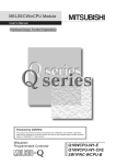
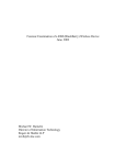
Setting monitoring timer
Set the monitoring timer of a watchdog timer.
System watchdog timer
[CPU Parameter] "RAS Setting" "WDT (Watchdog Timer) Setting"
Window
Displayed items
Item
Description
Setting range
Default
Monitoring time
Set the execution monitoring time to the system WDT.
20 to 2000 ms (10 ms units)
1000 ms
User watchdog timer
Set the user watchdog timer within the range of 100 ms to 10000 ms (10 ms unit) with the C Controller module dedicated
function (CCPU_StartWDT).
If the monitoring range is not set with the C Controller module dedicated function, the user watchdog timer
does not work.
32
4 BASIC FUNCTIONS
4.1 Program Monitoring Function (WDT)
Timeout of watchdog timer
The following shows the timeout conditions and the process of a watchdog timer.
Conditions for timeout
■System watchdog timer
In case of failure of C Controller module hardware and interrupt program execution, timeout will occur as the system
processing has been suspended for a long time.
■User watchdog timer
If the user program cannot complete the processing within the time specified using the C Controller module dedicated function
(CCPU_StartWDT), and also cannot execute the C Controller module dedicated function (CCPU_ResetWDT), timeout will
4
occur.
Processing at timeout
A watchdog timer error occurs and C Controller module will be in the following status.
• The BUS RUN LED turns OFF and the ERROR LED flashes. If a system watchdog timer error occurred, the READY LED
also turns OFF.
Resetting watchdog timer
The following shows how to reset a watchdog timer.
System watchdog timer
C Controller module resets system watchdog timer while executing fixed cycle processing.
User watchdog timer
User program resets user watchdog timer by executing the C Controller module dedicated function (CCPU_ResetWDT).
4 BASIC FUNCTIONS
4.1 Program Monitoring Function (WDT)
33
4.2
Clock Function
C Controller module has clock data internally. This clock is used to manage time for functions controlled by the system
including time stamp for the event history.
• The clock is running continuously using the internal battery of C Controller module while the module is in
OFF state or a power failure longer than the allowable momentary power failure time occurred.
• For the time stamp of a file, the time of the operating system is used. Since the time of the C Controller
module built-in clock and that of operating system may differ, correct the time of the operating system using
a user program.
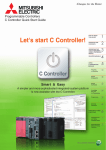
Setting clock data
The following shows the method for setting clock data.
Changing clock data
The clock data can be changed in one of the following methods:
• CW Configurator
• C Controller module dedicated function
When the clock data is changed, the following operations are performed:
• The millisecond clock is reset to '0'.
• "Clock setting" (event code: 24000) is saved in the event history file.
■Using CW Configurator
[Online] "Set Clock"
■Using C Controller module dedicated function
Write the clock data by using the C Controller module dedicated function (CCPU_SetRTC).
C Controller module sets the time of its built-in clock to that of the operating system at the startup of the
module after powering ON or resetting it. Use a user program in order to set the time for a running operating
system.
Reading clock data
Read the clock data by using the C Controller module dedicated function (CCPU_GetRTC).
Precautions
■When using this function for the first time
Since the clock data is not set at the factory, be sure to set the certain data.
■When modifying the clock data
Even if changing a portion of the clock data, be sure to write all data to the C Controller module again.
■When changing clock data with a user program
To change the clock data with a user program, be sure to use the C Controller module dedicated function (CCPU_SetRTC). If
other clock data setting function is used, the accurate clock data will not be set in the C Controller module.
34
4 BASIC FUNCTIONS
4.2 Clock Function
Setting time zone
Set the time zone used in C Controller module. Specifying the time zone enables the clock of C Controller module to work in
the local time zone.
[CPU Parameter] "Operation Related Setting" "Clock Related Setting"
Window
4
Displayed items
Item
Description
Time Zone
Sets the time zone used in C Controller module.
Comment
Enter a comment such as a name of the city for the time zone.
Setting range
•
•
•
•
•
•
•
•
•
•
•
•
•
•
•
•
•
•
•
•
•
•
•
•
•
•
•
•
•
•
•
•
•
•
UTC+13
UTC+12
UTC+11
UTC+10
UTC+9:30
UTC+9
UTC+8
UTC+7
UTC+6:30
UTC+6
UTC+5:45
UTC+5:30
UTC+5
UTC+4:30
UTC+4
UTC+3:30
UTC+3
UTC+2
UTC+1
UTC
UTC-1
UTC-2
UTC-3
UTC-3:30
UTC-4
UTC-4:30
UTC-5
UTC-6
UTC-7
UTC-8
UTC-9
UTC-10
UTC-11
UTC-12
Default
UTC+9
1 to 32 characters
• To apply the time zone setting on the C Controller module, reset the module or power cycle after writing
parameters.
• In the multiple CPU system, the time zone set in the CPU No.1 is used for other CPU modules. If the time
zone is set to the CPUs from No.2 to No.4, the setting is not applied.
Precautions
Once the module is initialized, the parameters will be restored to the default setting even when overseas time zone has been
set. Changing the clock of the module is required when the time zone is set again.
4 BASIC FUNCTIONS
4.2 Clock Function
35
4.3
Remote Operation Function
The operating status of C Controller module can be controlled with CW Configurator and a user program. For a control from a
user program, use C Controller module dedicated functions.
The following types of remote operation are available:
• Remote RUN/STOP
• Remote PAUSE
• Remote RESET
Remote RUN/STOP
Change the C Controller module status to RUN/STOP externally while the RESET/STOP/RUN switch is on the RUN position.
Use this function to change the C Controller module status to RUN/STOP when the module is located in an inaccessible place
such as in the control panel by using an external signal.
Executing remote operations
The following methods are available to execute remote RUN/STOP:
■Using CW Configurator
Refer to the following manual.
CW Configurator Operating Manual
■Using user program
Execute the C Controller module dedicated function (CCPU_Control) to perform remote RUN/STOP.
MELSEC iQ-R C Controller Module Programming Manual
■Using SLMP
Refer to the following manual.
SLMP Reference Manual
When "Clear" is selected for the device/label memory at the time of performing remote RUN from CW
Configurator, the following devices are cleared.
• X, Y, M, B, D, W
Precautions
Since C Controller module gives priority to STOP, observe the following considerations.
■STOP timing
C Controller module is stopped when remote STOP is performed from either of a user program or CW Configurator.
■Changing the remote STOP state to RUN again
Perform remote RUN.
■Output (Y) status during remote STOP
When "Output Mode Setting of STOP to RUN" is set to "Output the Output (Y) Status before STOP" in CW Configurator, the
output (Y) state is output when the state is changed from RUN to STOP at remote RUN.
■User program during remote STOP
The user program does not stop the execution even if the C Controller module is placed into the remote STOP state. To
change the processing according to the operating status of the C Controller module, use the C Controller module dedicated
function (CCPU_GetCpuStatus) in the program.
36
4 BASIC FUNCTIONS
4.3 Remote Operation Function
Remote PAUSE
Change the C Controller module status to PAUSE externally while the RESET/STOP/RUN switch is on the RUN position. Use
this function to retain the output (Y) of the C Controller module in the RUN state in such system as process control.
Executing remote operations
The following methods are available to execute remote PAUSE:
■Using CW Configurator
Refer to the following manual.
CW Configurator Operating Manual
4
■Using user program
Execute the C Controller module dedicated function (CCPU_Control) to perform remote PAUSE.
MELSEC iQ-R C Controller Module Programming Manual
■Using SLMP
Refer to the following manual.
SLMP Reference Manual
Precautions
The user program does not stop executing even if the C Controller module is in the remote PAUSE state. To change the
processing according to the operating status of the C Controller module, use the C Controller module dedicated function
(CCPU_GetCpuStatus) in the program.
Remote RESET
Reset the C Controller module externally while the module is in the STOP state (including the case in which the module is
stopped due to an error). Even when the RESET/STOP/RUN switch is on the RUN position, the C Controller module can be
reset while the module is in STOP state.
Enabling remote RESET
To perform the remote RESET, the remote RESET must be enabled.
[CPU Parameter] "Operation Related Setting" "Remote Reset Setting"
Window
Displayed items
Item
Description
Remote Reset
Set whether to enable the remote RESET.
Setting range
• Disable
• Enable
Default
Disable
4 BASIC FUNCTIONS
4.3 Remote Operation Function
37
Executing remote operations
The following methods are available to execute remote RESET:
■Using CW Configurator
Refer to the following manual.
CW Configurator Operating Manual
■Using user program
Execute the C Controller module dedicated function (CCPU_Reset) to perform remote RESET.
MELSEC iQ-R C Controller Module Programming Manual
■Using SLMP
Refer to the following manual.
SLMP Reference Manual
Precautions
■Before performing remote RESET
Close each user program in the C Controller module before performing remote RESET. Performing remote RESET while the
user program is being operated may damage the user program and data files.
■Status after the completion of remote RESET
After performing the remote RESET operation, the operating status of the C Controller module or programmable controller
CPU will be in the status set with the switch.
■Remote RESET at error stop
If remote RESET is performed when the C Controller module in a single CPU system or CPU No.1 in a multiple CPU system
has stopped due to an error, the C Controller module or programmable controller CPU will be in the status set with the switch.
■Remote RESET with CW Configurator
After the remote RESET is performed, the communication between CW Configurator and C Controller module will be
disconnected. In this case, reconnect the connection with CW Configurator.
■Remote RESET when CPU No.1 is a programmable controller CPU in a multiple CPU system
For remote RESET of programmable controller CPU, refer to the manual for the programmable controller CPU to be used.
■The host CPU is other than bus master CPU (CPU No.1)
• The parameter ("Enable" is set to "Remote Reset") is set in the bus master CPU (No.1): (Unset: Error)
• The bus master CPU (No.1) is STOP: (CPU is RUN/PAUSE: Error)
• The bus master CPU (No.1) is a programmable controller CPU
The programmable controller CPU (bus master CPU (CPU No.1) cannot be reset when other peripherals
(such as GX Works3) performs remote STOP to a programmable controller CPU (bus master CPU (CPU
No.1)). Therefore, cancel the remote STOP with the peripheral device performing the remote STOP. Then,
place the programmable controller CPU (bus master CPU (CPU No.1)) into STOP state with its RESET/
STOP/RUN switch, the remote operation with CW Configurator, or a user program (the mdControl function) of
the C Controller module.
• To perform remote RESET with CW Configurator, change the C Controller module status to STOP using
CW Configurator.
• To perform remote RESET with a user program, change the C Controller module status to STOP using a
user program.
38
4 BASIC FUNCTIONS
4.3 Remote Operation Function
Remote operation and operating status of C Controller module
The following shows the relationship between remote operations and operating status changes of C Controller module.
Status change by switch operation and at stop error
The following table shows the operating status of C Controller module by switch operation and at a stop error.
: No status change
Before changing the operating status
After changing the operating status
Factor to
determine CPU
operating
status
Operating status
RESET/STOP/
RUN switch
status
RESET/STOP/RUN switch
operation
RUN
STOP
RESET/STOP/
RUN switch
operation
STOP
STOP
RUN
RUN
RUN
STOP
STOP
STOP
STOP
PAUSE
(Actual status:
STOP)
STOP
PAUSE
RUN
(Actual status:
STOP)
STOP
RUN
STOP
RUN
PAUSE
RUN
STOP
STOP
RUN
RUN
STOP
STOP
STOP
STOP
PAUSE
(Actual status:
STOP)
STOP
PAUSE
RUN
(Actual status:
STOP)
STOP
RUN
Operation with
CW Configurator
or SLMP
Execution of the C
Controller module
dedicated function
Stop error
occurred
Stop error occurred
STOP
RUN
PAUSE
RUN
STOP
STOP
RUN
RUN
STOP
STOP
STOP
STOP
(Error STOP)
STOP
RUN
(Error STOP)
4 BASIC FUNCTIONS
4.3 Remote Operation Function
4
39
Status change by remote operations with CW Configurator and SLMP
The following table shows the operating status of C Controller module by remote operations with CW Configurator and SLMP.
: No status change
Before changing the operating status
After changing the operating status
Factor to
determine CPU
operating
status
Operating status
RESET/STOP/
RUN switch
status
Remote operation with CW Configurator and SLMP
RUN
STOP
PAUSE
RESET*1
RESET/STOP/
RUN switch
operation
STOP
STOP
RESET
RUN
RUN
STOP
PAUSE
STOP
STOP
RESET
PAUSE
(Actual status:
STOP)
STOP
RESET
RUN
(Actual status:
STOP)
STOP
RESET
Operation with
CW Configurator
or SLMP
Execution of the C
Controller module
dedicated function
Stop error
occurred
*1
40
STOP
RUN
RUN
PAUSE
RESET
PAUSE
RUN
RUN
STOP
RUN
RUN
STOP
PAUSE
STOP
STOP
RESET
PAUSE
(Actual status:
STOP)
STOP
RESET
RUN
(Actual status:
STOP)
STOP
RESET
STOP
RUN
RUN
PAUSE
RESET
PAUSE
RUN
RUN
STOP
RUN
RUN
STOP
PAUSE
STOP
STOP
(Error STOP)
(Error STOP)
(Error STOP)
RESET
STOP
RUN
(Error STOP)
(Error STOP)
(Error STOP)
RESET
Setting "Remote Reset Setting" to "Enable" of the CPU parameters is required.
4 BASIC FUNCTIONS
4.3 Remote Operation Function
Status change at the execution of the C Controller module dedicated function
The following table shows the operating status of C Controller module at the execution of the C Controller module dedicated
function (CCPU_Control).
: No status change
Before changing the operating status
After changing the operating status
Factor to
determine CPU
operating
status
Execution of the C Controller module dedicated function
RESET/STOP/
RUN switch
operation
Operation with
CW Configurator
or SLMP
Execution of the C
Controller module
dedicated function
Stop error
occurred
*1
Operating status
RESET/STOP/
RUN switch
status
RUN
STOP
PAUSE
RESET*1
STOP
STOP
RESET
RUN
RUN
STOP
PAUSE
STOP
STOP
RESET
PAUSE
(Actual status:
STOP)
STOP
RESET
RUN
(Actual status:
STOP)
STOP
RESET
STOP
RUN
RUN
PAUSE
RESET
PAUSE
RUN
RUN
STOP
RUN
RUN
STOP
PAUSE
STOP
STOP
RESET
PAUSE
(Actual status:
STOP)
STOP
RESET
RUN
(Actual status:
STOP)
STOP
RESET
STOP
RUN
RUN
PAUSE
RESET
PAUSE
RUN
RUN
STOP
RUN
RUN
STOP
PAUSE
STOP
STOP
(Error STOP)
(Error STOP)
(Error STOP)
RESET
STOP
RUN
(Error STOP)
(Error STOP)
(Error STOP)
RESET
4
Setting "Remote Reset Setting" to "Enable" of the CPU parameters is required.
4 BASIC FUNCTIONS
4.3 Remote Operation Function
41
4.4
I/O Module, Intelligent Function Module Access
Function
The I/O module and Intelligent function module(s), which are under the control of C Controller module, can be controlled by
creating user program using the C Controller module dedicated functions and MELSEC data link functions.
C Controller module
/*Output the output signal (Y) in bit (1-point) units.*/
ret=CCPU_Y_Out_BitEx();
/*Read the input signal (X) in word (16-point) units. */
ret=CCPU_X_In_WordEx();
/*Write data to the intelligent function module buffer memory.*/
ret=CCPU_ToBuf();
Function list
The following table shows the list of functions which can be used for accessing I/O modules and Intelligent function modules.
Function name
Description
CCPU_FromBuf
Reads data from the CPU buffer memory or the intelligent function module buffer memory of the module on the
specified position.
CCPU_FromBuf_ISR
CCPU_ToBuf
CCPU_ToBuf_ISR
Writes data to the CPU buffer memory and the intelligent function module buffer memory of the module on the specified
module position.
CCPU_X_In_BitEx
Reads the input signal (X) in bit (1-point) units.
CCPU_X_In_WordEx
Reads the input signal (X) in word (16-point) units.
CCPU_X_In_Word_ISR
CCPU_Y_In_BitEx
Reads the output signal (Y) in bit (1-point) units.
CCPU_Y_In_WordEx
Reads the output signal (Y) in word (16-point) units.
CCPU_Y_In_Word_ISR
CCPU_Y_Out_BitEx
Outputs the output signal (Y) in bit (1-point) units.
CCPU_Y_Out_WordEx
Outputs the output signal (Y) in word (16-point) units.
CCPU_Y_Out_Word_ISR
42
mdDevRstEx
Resets (turns OFF) bit device(s).
mdDevSetEx
Sets (turns ON) bit device(s).
mdRandREx
Reads device(s) randomly.
mdRandWEx
Writes device(s) randomly.
mdReceiveEx
Reads devices in batch.
mdSendEx
Writes devices in batch.
4 BASIC FUNCTIONS
4.4 I/O Module, Intelligent Function Module Access Function
4.5
Interrupt Function from Modules
The following processes can be performed by issuing interrupt request from an input module, Intelligent function module,
interrupt module, and other CPU modules.
To perform the interrupt function from module, setting "module parameters" for each module is required. For
more details, refer to the user's manual for the respective modules.
• The routine registered with the C Controller module dedicated function (CCPU_EntryInt) can be executed as an interrupt
routine (interrupt program).
• The user program of which status is interrupt event wait state by using the C Controller module dedicated function
4
(CCPU_WaitUnitEvent) can be re-executed.
C Controller module dedicated
function
Description
CCPU_EntryInt
Registers a routine so that the routine can be called when an interrupt occurs.
CCPU_EnableInt
Enables the registered routine.
CCPU_EnableInt_ISR
CCPU_DisableInt
Disables the registered routine.
CCPU_DisableInt_ISR
CCPU_WaitUnitEvent
Waits for an interrupt event notification from Intelligent function module or an interrupt module.
Factor of interrupt pointer number
The following shows the interrupt factors for each interrupt pointer number.
Factor
Interrupt pointer number
Description
Interrupt from module
I0 to I15
A pointer used in the module which has an interrupt function.
Inter-module synchronous interrupt
I44
A fixed cycle interrupt pointer used for the inter-module synchronization
function.
Multiple CPU synchronous interrupt
I45
A fixed cycle interrupt pointer used for the multiple CPU synchronization
function.
Interrupt from module
I50 to I1023
A pointer used in the module which has an Interrupt function.
Interrupt priority
The priority has been set to each interrupt pointer. If the priority of an interrupt program of which execution conditions have
been satisfied is higher than that of an interrupt program that is currently being executed, the program is executed in
accordance with the priority. If the priority of an interrupt of which execution conditions have been satisfied is lower, it will be in
a wait state until an interrupt program that is currently being executed is completed.
Interrupt priority
Interrupt pointer
Execution order at simultaneous
occurrence
High
3
Inter-module synchronous interrupt (I44), multiple CPU synchronous interrupt
(I45)
I45 I44
Low
8
Interrupt from module (I0 to I15, I50 to I1023)
I0 I1 I2 to I1021 I1022 I1023
4 BASIC FUNCTIONS
4.5 Interrupt Function from Modules
43
Using interrupt function
The following explains the usage of the interrupt function from module.
Executing interrupt routine
The following shows how to execute the interrupt routine.
1.
Register the routine that corresponds to the interrupt from a module with the C Controller module dedicated function
(CCPU_EntryInt).
2.
Enable the registered routine with the C Controller module dedicated function (CCPU_EnableInt,
CCPU_EnableInt_ISR).
3.
When the interrupt from module is issued after the routine is enabled, the registered routine is executed as an interrupt
routine.
C Controller Module
(User program)
1. Execute the CCPU_EntryInt function.
2. Execute the CCPU_EnableInt function.
Interrupt routine (interrupt program)
registration table
Interrupt routine (interrupt program) 1
Interrupt routine (interrupt program) 2
(Empty)
Execute an interrupt routine (interrupt program).
3. Issue an interrupt.
Stopping interrupt routine
Disable the registered routine with the C Controller module dedicated function (CCPU_DisableInt, CCPU_DisableInt_ISR).
Precautions
When an interrupt from module is issued to the routine disabled with the C Controller module dedicated function
(CCPU_DisableInt, CCPU_DisableInt_ISR), the interrupt from module is ignored. The routine is executed only for the interrupt
from module which has been issued while the routine is enabled with the C Controller module dedicated function
(CCPU_EnableInt, CCPU_EnableInt_ISR).
44
4 BASIC FUNCTIONS
4.5 Interrupt Function from Modules
Restarting user programs
The following shows how to restart the user program.
1.
2.
3.
4.
Execute the C Controller module dedicated function (CCPU_WaitUnitEvent).
The user program will be in an interrupt event wait state.
Issue the interrupt event from the module.
After receiving the interrupt event, the user program is restarted.
C Controller Module
(User program)
4
1. Execute the CCPU_WaitUnitEvent function.
User program is being executed.
2. In an interrupt event wait state
4. Restart user program.
Interrupt event notification
3. Issue an interrupt.
Precautions
The following shows the considerations when using C Controller module dedicated function (CCPU_WaitUnitEvent).
■When an interrupt event has already been notified at execution of the function
When an interrupt event has already been notified from Intelligent function module or interrupt module at execution of the C
Controller module dedicated function (CCPU_WaitUnitEvent), the user program is restarted from the interrupt event wait state
at the same time as execution of the C Controller module dedicated function (CCPU_WaitUnitEvent). In addition, when
multiple interrupt events have been notified to the same interrupt event number at execution of the C Controller module
dedicated function (CCPU_WaitUnitEvent), the user program performs processing as a single interrupt event notification.
■When using the function in multiple user programs
Do not set the same CPU number and same interrupt event number in multiple user programs. Doing so results in uncertainty
as to which user program receives an interrupt event.
4 BASIC FUNCTIONS
4.5 Interrupt Function from Modules
45
4.6
Fixed Cycle Processing Function
The fixed cycle processing function is a function to refresh with Network modules or to perform communication with external
devices.
The following processes are performed with the fixed cycle processing function.
• Refresh processing with Network modules (Link refresh)
• Reset processing of watchdog timer
• Self-diagnostics processing
Setting fixed cycle processing interval
The following shows the setting method for the cycle that the fixed cycle processing function operates.
[CPU Parameter] "Operation Related Setting" "Refresh Cycle Setting"
Window
Displayed items
Item
Description
Setting range
Default
Refresh Cycle
Set the interval that the fixed cycle processing function operates.
1 to 2000 ms (1 ms
units)
100 ms
Set the value that satisfies the following relational expression for the cycle of the fixed cycle processing. An
error will occur when the following expression is not satisfied.
• Setting time of the program monitoring function (WDT) > Cycle of the fixed cycle processing
Checking interval
The following shows the method to check the interval (maximum value/minimum value/current value) at which the fixed cycle
processing function operates.
Checking with a function
The interval can be obtained using the C Controller module dedicated function (CCPU_GetConstantProcessStatus).
Checking with special registers
The interval at which the function operates is stored in special registers (SD520/SD522/SD524). (Page 176 Special
Register List)
46
4 BASIC FUNCTIONS
4.6 Fixed Cycle Processing Function
4.7
Inter-module Synchronization Function
The inter-module synchronization function is a function to adjust the input or output timing of modules to be synchronized to
the inter-module synchronization cycle by matching the control timing of signals among multiple modules.
Input module
Output module
A/D converter module
C Controller module
D/A converter module
4
Inter-module synchronization cycle
C Controller module
Inter-module synchronization cycle
Program
Inter-module synchronous
interrupt program (I44)
A/D converter module
(set as a synchronization target)
D/A converter module
(set as a synchronization target)
Input module
(set as a synchronization target)
Output module
(set as a synchronization target)
Operation processing
Input
Operation processing
Output
conversion
Input
Operation processing
Output
conversion
Input
Output
Output
Input
Input
Input
Output
Output
Output
Output
For details on the inter module synchronization function, refer to the following manual.
MELSEC iQ-R Inter-Module Synchronization Function Reference Manual
4 BASIC FUNCTIONS
4.7 Inter-module Synchronization Function
47
Fixed cycle synchronization function
The fixed cycle synchronization function is a function to synchronize multiple modules at the timing of the inter-module
synchronization cycle to perform data communication and input/output control at a fixed cycle. Using this function enables the
accurate speed to be obtained by the encoder input at the fixed cycle, and also enables the highly accurate model prediction
control by the accurately-tracked input/output timing.
Although the shorter interval of the inter-module synchronization cycle provides the more accurate
synchronous control, the size of program executable in the inter-module synchronous interrupt program will
be smaller. By lengthening the interval of the inter-module synchronization cycle, the program with bigger size
can be executed. However, the accuracy of the synchronous control will be reduced.
To use the fixed cycle synchronization function, consider the program size to be executed.
Synchronization timing of C Controller module
C Controller module executes the inter-module synchronous interrupt program (I44) at every inter-module synchronization
cycle. Synchronization between C Controller module and respective modules is performed at the timing of refresh before and
after the inter-module synchronous interrupt program (I44). This will enable C Controller module to import the input data and
to write the output data at the timing of the inter-module synchronization cycle.
Inter-module synchronization cycle
Inter-module synchronous interrupt
program execution time
Normal program
Interrupted
Executed
Executed
Inter-module synchronous interrupt program
Input refresh
External device
Input
Operation
processing
Output refresh
Input
Output
(Link device)
(Link device)
Input
Output
(X, Buffer memory)
(Y, Buffer memory)
External device Input
Input modules
Output
Output
External device
External device
Output modules
Inter-module synchronous interrupt
Interrupt programs are executed at the timing of the inter-module synchronization cycle set with the parameters. The interrupt
programs executed at every inter-module synchronization cycle is referred to as the inter-module synchronous interrupt
program (I44).
• Describe the control programs to be synchronized in the inter-module synchronous interrupt program (I44).
• The operation when an interrupt factor arises and the program creation method are the same as normal
interrupt program.
■Execution timing
The inter-module synchronous interrupt program (I44) is executed at the timing of the inter-module synchronization cycle. The
inter-module synchronous interrupt program (I44) is registered using the interrupt function form module. (Page 43
Interrupt Function from Modules)
48
4 BASIC FUNCTIONS
4.7 Inter-module Synchronization Function
Processing of inter-module synchronous interrupt program (I44)
The following describes the processing of the inter-module synchronous interrupt program (I44).
■Input refresh (CC-Link IE Field Network module)
At the input refresh, link devices (RX, RWr) are refreshed from the CC-Link IE Field Network module to be synchronized.
■Operation processing
• To import the input signal (X) and the input from the buffer memory, use the C Controller module dedicated functions
(CCPU_X_In_Word_ISR, CCPU_FromBuf_ISR).
• To import the output signal (Y) and the output to the buffer memory, use the C Controller module dedicated functions
(CCPU_Y_Out_Word_ISR, CCPU_ToBuf_ISR).
4
■Output refresh (CC-Link IE Field Network module)
In the output refresh, link devices (RY, RWw) are refreshed to the CC-Link IE Field Network module to be synchronized.
Refresh timing
The following describes the refresh timing depending on the operating status of C Controller module.
■Operation in the STOP state (RUN to STOP)
• C Controller module turns OFF the output when it is in the STOP state due to user operation (such as user program or
switch operation). Refresh is performed continuously during the STOP state.
• C Controller module turns OFF the output and also stops the refresh when the stop error occurred because of any failure of
C Controller module or respective modules.
The inter-module synchronous interrupt program (I44) does not stop even if C Controller module is in the
STOP state.
Precautions
When the system parameter of the inter-module synchronization function is rewritten while the C Controller module is in the
STOP state, it will not applied by switching to the RUN state, and the C Controller module operates with the parameter before
the rewrite.
Interaction with cycle of the fixed cycle communication of the
multiple CPU system function
The cycle of the fixed cycle communication of the multiple CPU system function can be matched with the inter-module
synchronization cycle.
By adjusting the cycle of the fixed cycle communication to the inter-module synchronization cycle, the input/output of modules
having different control CPUs can be synchronized. The interaction with the multiple CPU system function is set with the
parameter. (Page 126 Fixed cycle communication setting)
A/D converter module
(controlled by CPU No.1)
C Controller module (CPU No.1)
A/D converter module
(controlled by CPU No.2)
The input/output of modules
controlled by different CPUs can
be synchronized.
C Controller module (CPU No.2)
4 BASIC FUNCTIONS
4.7 Inter-module Synchronization Function
49
Operation of program
Once the inter-module synchronization cycle is interacted with the cycle of the fixed cycle communication, a multiple CPU
synchronous interrupt program (I45) and an inter-module synchronous interrupt program (I44) are executed in each intermodule synchronization cycle.
The multiple CPU synchronous interrupt program (I45) is executed first, and then the inter-module synchronous interrupt
program (I44) is executed. Two inter-module synchronization cycles are required for data obtained by the host CPU to reach
to the other CPUs, and delaying the output timing of the controlled module of the host CPU and the controlled module of other
CPUs for two cycles is required for the output synchronized among CPU modules.
For C Controller module, only the link devices of CC-Link IE Field Network module (RX, RY, RWr, and RWw)
are refreshed at the 'input refresh' and 'output refresh' in an inter-module synchronous interrupt program. To
import the I/O signals (X, Y) and the values from the buffer memory, use the C Controller module dedicated
function.
For details on processing of each interrupt program of C Controller module, refer to the following section.
• Inter-module synchronous interrupt program (I44)
Page 48 Fixed cycle synchronization function
• Multiple CPU synchronous interrupt program (I45)
Page 135 Multiple CPU synchronous interrupt
(1)
CPU No.1
Program execution
processing
Cycle of fixed cycle communication
Inter-module synchronization cycle
Multiple CPU synchronous interrupt program
Normal program
Operation processing
Multiple CPU synchronous interrupt program
Inter-module synchronous interrupt program
Input
refresh
Operation
processing
Input modules
(Link device)
Output
refresh
Normal program
Do not set data here even
though data can be output at
the next inter-module
synchronization cycle.
Ò Acquire an input value.
Input modules
(X, Buffer memory)
Cycle of fixed cycle communication
Inter-module synchronization cycle
Operation processing
Inter-module synchronous interrupt program
Input
refresh
Operation
processing
Output
refresh
Cycle of fixed cycle communication
Inter-module synchronization cycle
Multiple CPU synchronous interrupt program
Normal program
Do not set data here even
Output data Ó Write data to the fixed
though data can be output at
cycle communication area. the next inter-module
synchronization cycle.
Operation processing
Inter-module synchronous interrupt program
Input
refresh
Operation
processing
Output
refresh
Normal program
Output data
(Link device)
Output data
Ö Set an output value.
Input data
Output data
(Y, Buffer memory)
Ô Fixed cycle communication
Fixed cycle communication area
Fixed cycle communication
Fixed cycle communication
Fixed cycle communication
Fixed cycle communication
Fixed cycle communication area
Input data
Multiple CPU synchronous interrupt program
Normal program
Operation processing
Inter-module synchronous interrupt program
Input
refresh
Operation
processing
Output
refresh
Multiple CPU synchronous interrupt program
Normal program
Operation processing
Inter-module synchronous interrupt program
Input
refresh
Operation
processing
Output
refresh
Õ Read data from the fixed cycle communication area.
Multiple CPU synchronous interrupt program
Normal program
Operation processing
CPU No.2
Program execution
processing
Inter-module synchronous interrupt program
Input
refresh
(2)
Operation
processing
Output
refresh
Normal program
Output data
(Link device)
Ö Set an output value.
Output data
(Y, Buffer memory)
Cycle of fixed cycle communication
Inter-module synchronization cycle
Cycle of fixed cycle communication
Inter-module synchronization cycle
Cycle of fixed cycle communication
Inter-module synchronization cycle
Create the program so that the two cycles of the output differences are offset.
(1): Write the input value to the fixed cycle communication area of CPU No.1.
(2): Set the output value by reading data from the fixed cycle communication area of CPU No.1.
Precautions
Considerations for interaction with cycle of fixed cycle communication are shown below:
• Selecting "Use" for the inter-module synchronization function enable "Cooperate" to be selected for "Fixed Scan
Communication Function and Inter-module Synchronization Function". It cannot be selected when "Not use" is selected for
the inter-module synchronization function.
• Even if "I/O Setting Outside Group" is enabled in a program of other CPU, importing the input or output from the module to
be synchronized is not available. Although it can be read by direct specification such as DX, DY, Un\Gn, or the C Controller
module dedicated function (CCPU_FromBuf), inconsistency of data may occur.
• To adjust the start of the inter-module synchronization function among all CPUs, confirm that the inter-module
synchronization function is available by checking the ready flag of CPU No.n from SM220 to SM223 turns ON. By using
SM220 to SM222 in an interlock program, the start of the inter-module synchronization function can be matched among all
CPUs.
50
4 BASIC FUNCTIONS
4.7 Inter-module Synchronization Function
Parameter setting
Set a module configuration diagram with CW Configurator to configure the inter-module synchronization setting.
[System Parameter] "Synchronization Setting within the Modules" "Synchronization Setting within the Modules"
Operating procedure
1.
Select "Use" for "Use Inter-module
Synchronization Function in System".
2.
3.
Click the "Detailed Setting" for "Select
Synchronous Target Unit between Unit".
4
Select "Synchronize" for the module to be
synchronized.
4.
Set the inter-module synchronization cycle in
"Synchronous Fixed Scan Interval Setting
within the Modules".
5.
When writing parameters, write both of the
6.
system parameter and module parameter.
Configure the setting for the synchronous
master when a local station of CC-Link IE Field
Network module is to be synchronized. (The
setting is not required for a master station.)
Displayed items
Item
Description
Use Inter-module Synchronization Function in System
Set whether or not to use the inter-module
synchronization function.
• Not Use
• Use
Not Use
Select Synchronous
Target Unit between Unit
Detailed Setting
Set the module to be synchronized.
• Do not Synchronize
• Synchronize
Do not
Synchronize
Synchronous Fixed
Scan Interval Setting
within the Modules*1
0.05ms Unit Setting
Set whether or not to set the inter-module
synchronization cycle in 0.05 ms units.
• Not Set
• Set
Not Set
Fixed Scan Interval Setting
(Not Set by 0.05ms)
Select the inter-module synchronization cycle from
the list when it is not set in 0.05 ms units.
•
•
•
•
•
•
0.888ms
Fixed Scan Interval Setting
(Set by 0.05ms)
Set the inter-module synchronization cycle when it is
set in 0.05 ms units.
Synchronous Master Setting
of CC IE Field
When "Set" is selected, a master station of CC-Link
IE Field Network module is the synchronous master.
When "Not Set" is selected, the CPU module (the
leftmost CPU module for multiple CPU configuration)
is the synchronous master.
Mounted Slot No.
Set the mounting slot number for the master station
of CC-Link IE Field Network module to be set as the
synchronous master.
Synchronous Master
Setting within the
Modules
*1
Setting range
0.222ms
0.444ms
0.888ms
1.777ms
3.555ms
7.111ms
0.10 to 10.00 ms (in 0.05
ms units)
• Not Set
• Set
0 to 11
Default
0.50ms
Not Set
0
The setting range for the inter-module synchronization cycle differs depending on modules. ( Manual for respective modules)
4 BASIC FUNCTIONS
4.7 Inter-module Synchronization Function
51
To interlink with the cycle of the fixed cycle communication of the multiple CPU system function, set "Fixed
Scan Communication Function and Inter-module Synchronization Function" under "Fixed Scan
Communication Setting" to "Cooperate". (Page 126 Data Communication Between CPU Modules)
4.8
Output Mode Setting Function from STOP to RUN
This function sets the mode of the output (Y) when C Controller module operating status is switched from STOP to RUN.
[CPU Parameter] "Operation Related Setting" "Output Mode Setting of STOP to RUN"
Window
Displayed items
Item
Description
Output Mode Setting of
STOP to RUN
Set the operation of the output (Y)
when the operating status is switched
from STOP to RUN.
Setting range
• Output the Output (Y) Status before
STOP
• Clear the Output (Y)
Default
Output the Output (Y) Status before
STOP
Output the Output (Y) Status before STOP
After the output (Y) status before the operating status turns into STOP state is output, the user program is executed.
Clearing output (Y)
The output (Y) is turned OFF, and the output (Y) status is output after the program operations are executed.
Precautions
The following shows the considerations on outputs when changing the status from STOP to RUN after forcing the output (Y)
ON at STOP status.
■When "Output the Output (Y) Status before STOP" is selected
• When the output (Y) is forced ON when the operating status is STOP, the status before it stopped is output.
• If the output (Y) is OFF before entering the STOP state, the ON state is not retained.
■When "Clear the Output (Y)" is selected
• When the output (Y) is forced ON when the operating status is STOP, the ON state is retained.
52
4 BASIC FUNCTIONS
4.8 Output Mode Setting Function from STOP to RUN
4.9
Memory Card Function
This section explains the functions that use an SD memory card.
Boot operation
The files stored on the SD memory card are transferred to the storage memory which is automatically determined by the C
Controller module when the module is powered OFF ON or reset.
To perform the boot operation, enabling "Memory card parameter execution" under "Service Settings" is
required. (Page 65 Service settings)
4
Boot operation procedure
1.
2.
3.
4.
Configure the boot setting.
Insert an SD memory card.
Write the boot setting and boot file on the SD memory card.
Power OFF ON or reset the C Controller module.
Boot setting
[Memory Card Parameter] [Boot Setting]
Operating procedure
1.
Click "<Detailed Setting>" in "Boot File Setting".
2.
Click on the "Type" column. The maximum number of boot
files that can be specified is the same as the number of
files that can be stored in the storage memory.
3.
Select the type for the boot file. (Two or more parameters
can be selected.)
4.
Click the [Add] button to add the file(s).
Displayed items
Item
Description
Setting range
Default
Boot File Setting
Set the file used for boot operation from the SD memory card.
4 BASIC FUNCTIONS
4.9 Memory Card Function
53
Maximum number of boot files allowed
The maximum number of boot files allowed is 512. However, the maximum number of boot files is the same as the number of
files possible to be stored in the transfer destination memory because more than one file is bootable for a single setting.
Precautions
• When a parameter file is set as a boot file, the parameter file in the transfer destination C Controller module is overwritten.
In addition, if a parameter file is not set as a boot file even when it is stored on the SD memory card, the CPU module
operates in accordance with the settings in the parameter file in it.
Enable/disable the use of file/data on memory card
Set whether to use files/data stored on a memory card.
Window
Displayed items
54
Item
Description
Module Extended Parameter
Set whether to use the module extended parameters stored on the SD
memory card.
4 BASIC FUNCTIONS
4.9 Memory Card Function
Setting range
• Not Use
• Use
Default
Not Use
4.10
RAS Function
Self-diagnostic function
This function is for C Controller module to diagnose the presence of any abnormality by itself.
Self-diagnostics timing
If an error occurred when the C Controller module is powered ON or while it is in the RUN/STOP state, the detected error
information is displayed, and the operation is stopped.
4
However, depending on the error occurrence status or the instruction to execute, the C Controller module may
not be able to detect the error. Configure safety circuits external to the system to ensure that the entire system
operates safely even in such a case.
Error checking methods
The following are the error checking methods.
■Checking with special relays or special registers
When C Controller module detects any error, the special relays (SM0, SM1) turns ON, and an error code corresponding to the
error is stored in the special register (SD0). If more than one error is detected, the latest error code is stored in the special
register (SD0). Use the special relay (SM0, SM1) and special register (SD0) in the program for the C Controller module or
mechanical interlock. In addition, up to 16 error codes (latest errors occurred on the system) will be stored in the special
registers (SD10 to SD25). (The error codes for the 17th and onwards will not be stored.)
■Checking with CW Configurator
The error occurrence of the entire system, latest errors occurred, and event history can be checked on the module diagnostic
screen. ( CW Configurator Operating Manual)
• In the C Controller module, maximum 16 latest errors occurred can be displayed. In addition, if an additional error occurs
after a stop error, the error information is not updated.
• Error logs can be checked using the event history function. (Page 60 Event history function)
The maximum number of continuation errors and stop errors to be displayed is 15 and 2 respectively. If
already 15 continuation errors have been displayed, then next continuation error will not be displayed. If the
error of the same code has been displayed, the date and time of occurrence and the detailed information
about the relevant error is updated.
Operation at error detection of Intelligent function module
If an error is detected with the self-diagnostic function, C Controller module operates in accordance with the setting of "CPU
Module Operation Setting at Error Detected" as follows. (Page 57 Operation setting upon an error detection in Intelligent
function module)
■When "Stop" is selected in "CPU Module Operation Setting at Error Detected"
When an error is detected, the operation depends on the setting of "Output Mode upon CPU Error" in the Module Parameter
of each module.
• When "Clear" is set: Output to the corresponding module is turned OFF.
• When "Hold" is set: Output to the corresponding module is retained.
For the setting method of module parameter, refer to the manual for each module.
■When "Continue" is selected in "CPU Module Operation Setting at Error Detected"
C Controller module does not stop.
4 BASIC FUNCTIONS
4.10 RAS Function
55
Error Detections Setting
Set whether the error is detected.
[CPU Parameter] "RAS Setting" "Error Detections Setting"
Window
Displayed items
Item
Description
Module Verify Error*1
Set whether to detect the module verification error.
Fuse Blown
Set whether to detect the fuse blown in the controlled
module.
Synchronous Interrupt
Program (I44, I45)
Executing Time
Excessive
*1
Execution Interval Exceed (I44, I45)
Set whether to detect the excessive execution time (I44,
I45).
Program Execution Section Exceed
(I45)
Set whether to detect the program execution section
exceed errors (I45).
Setting
range
• Detect
• Not
Detected
Default
Detect
Not Detected
If an operating module in which "Not Detected" is selected in the parameter is removed, a module verification error is not detected,
however, a stop error may occur if accessing the removed module by using programs, etc. Since the removed module is not accessible
even if it is mounted again, accessing the module by changing the module status from STOP to RUN may result in a stop error.
Operation settings when an error is detected
Set the operation of C Controller module when an error is detected.
[CPU Parameter] "RAS Setting" "CPU Module Operation Setting at Error Detected"
Window
Displayed items
56
Item
Description
Memory Card Error
Set the C Controller module operation upon a memory
card error.
Module Verify Error
Set the C Controller module operation upon a module
verification error.
Fuse Blown
Set the C Controller module operation upon fuse
blown error.
Synchronous Interrupt Execution Interval Error (CPU Module)
Set the operation of CPU module at a synchronous
interrupt execution interval error.
4 BASIC FUNCTIONS
4.10 RAS Function
Setting
range
• Stops
• Continues
Default
Stops
Operation setting upon an error detection in Intelligent function module
The operation of C Controller module when an error occurred in an Intelligent function module will be determined with the
parameter setting of "CPU Module Operation Setting at Error Detected" under "I/O Assignment Setting".
[System Parameter] [I/O Assignment Setting] "I/O Assignment Setting"
Window
4
Displayed items
Item
Description
CPU Module Operation Setting at
Error Detection
Set the operation of C Controller
module at the detection of a major
error or moderate error in the
configured module.
Setting range
• Critical: Stop, Moderate: Continue
• Critical: Stop, Moderate: Stop
• Critical: Continue, Moderate:
Continue
Default
Critical: Stop, Moderate: Stop
LED display setting
Sets whether to turn the ERROR LED ON/OFF.
[CPU Parameter] [RAS Setting] "LED Display Setting"
Window
Displayed items
Item
ERROR LED
Description
Minor Error (Continue
Error)
Set whether to turn the ERROR LED ON when a minor error occurred.
Setting
range
• Display
• Do Not
Display
Default
Display
Operation settings at stop error in multiple CPU function
Set whether to stop all CPUs when a major or moderate error occurs on each CPU in a multiple CPU configuration. (Page
118 Stop setting)
4 BASIC FUNCTIONS
4.10 RAS Function
57
Error clear function
This function clears all the existing continuation errors at once.
Continuation
error occurs.
Continuation
error occurs.
No continuation
error occurs.
· Power shutoff
· Battery error
Clear the error.
CW Configurator
Error that can be cleared
Only the following continuation errors can be cleared.
58
Error code
Error name
1000H
Power shutoff
1080H
ROM write count error
1100H
Memory card access error
1120H
SNTP clock setting error
1124H
Default gateway/gateway IP address error
1128H
Own node port number error
1129H
Open specification port number error
112DH
Specified IP address error
112EH
Connection establishment failed
1133H
Socket communications response send error
1134H
TCP connection timeout
1152H
IP address error
1155H
Connection number acquisition error
1157H
Receive buffer securement error
1165H
UDP/IP send failed
1166H
TCP/IP send failed
1167H
Unsend data send error
1200H, 1210H
Module moderate error
1220H
Other CPU module moderate error
1240H, 1241H
Inter-module synchronization processing error
1260H, 1262H
Multiple CPU synchronization processing error
1830H
Receive queue full
1831H
Receive processing error
1832H
Transient data error
1840H
Memory card error
1843H
Internal buttery failure
1846H
Refresh cycle exceeded
2120H, 2121H
Memory card error
2400H, 2401H
Module verification error
2420H
Fuse blown error
2441H, 2442H
Module major error
2450H
Detection of module major error
2461H, 2462H
Other CPU module major error
2470H
Other CPU module major error
2610H
Inter-module synchronization signal error
4 BASIC FUNCTIONS
4.10 RAS Function
Error code
Error name
2630H
Multiple CPU synchronization signal error
Method for clearing error
The following shows how to clear errors.
■Using CW Configurator
Clear errors with the module diagnostic function of CW Configurator. ( CW Configurator Operating Manual)
■Using user programs
1.
2.
3.
Check the continuation error detected by the C Controller module dedicated function (CCPU_GetErrInfo).
Clear the cause of the currently detected continuation errors.
4
Execute the C Controller module dedicated function (CCPU_ClearError).
Precautions
• Since this function clears all the detected continuation errors at once, unintended errors may also get cleared.
• This function does not remove the cleared errors from the event history.
• Any errors occurred in a module other than the C Controller module cannot be cleared by this function.
4 BASIC FUNCTIONS
4.10 RAS Function
59
Event history function
C Controller module collects and saves the error information such as errors detected by the module, operations done for the
module, and network errors from each module. The saved operation and error occurrence information can be checked and
viewed in chronological order.
Using this function enables to investigate the problems that have occurred in the equipment/devices, check the update related
to control data in C Controller system, and detect any unauthorized access.
The information of events that occurred in
the host CPU and modules controlled by
the host CPU are collected by the CPU
module in batch and saved.
CW Configurator
The event information that is held in the CPU
module is displayed with Engineering tool.
The event history information is constantly collected regardless of the operating state of the C Controller
module. In some cases; however, the event history information may not be collected due to a major error in a
module, a base unit error, a cable failure, or others.
Event history settings
Under normal circumstances, the event history function can be used with its default settings and doesn't need to be manually
configured. The storage memory and file size of the event history file can be changed if desired.
[CPU Parameter] [RAS Setting] "Event History Setting"
Window
Displayed items
Item
Description
Save Destination
Specify the storage destination of event history files.
Set Save Volume of Per File
Specify the storage capacity per event history file.
Setting range
• Data Memory
• Memory Card
1 to 2048 KB
■Registration from user program
Event logs can be registered from a user program by executing the C Controller module dedicated function
(CCPU_RegistEventLog). In this case, the event type will be "Operation".
60
4 BASIC FUNCTIONS
4.10 RAS Function
Default
Data Memory
128 KB
Saving event history
■Modules from which event history information is collected
Event history information is collected from the C Controller module and other modules mounted on the same Base unit (such
as the main base unit and any additional extension base units). Event history information may or may not be collected from
devices on the network depending on the specifications of the Network modules used to connect to them. For more
information including the coverage of event history collection regarding devices on the network, refer to the manual of each
module. For a multiple CPU system, each CPU logs only events detected on the modules under its control.
■Events to be saved
The detailed information such as the operation initiator information are saved for troubleshooting purpose when the event
history is saved. For the event to be saved as the event history by C Controller module, refer to the event list. (Page 60
4
Event history function)
Event history file
The storage destination memory and file size for event history files can be changed in the event history setting. (Page 60
Event history settings)
■Storage destination memory
The storage destination memory is set to either the data memory or SD memory card.
When an SD memory card is selected, disable the write protect switch of the SD memory card. If it is enabled, an event
history will not be stored. (Reading the event history file in the SD memory card using CW Configurator is possible.)
If the write protect switch of SD memory card is enabled, the write error will occur, because, during system operation, an
attempt to write an event occurred will failed as the write protect switch is enabled. An error can be checked with the Module
Diagnostic function immediately after the error occurred, but the same information can not be checked after power cycle or
reset since errors are not saved.
For a system for which file write occurs frequently or the system of which state frequently changes because of
the unstable communication, the file size of the event history must be larger enough to store a greater number
of events. In this case, using an SD memory card is recommended as the storage memory.
■File size
If the specified size is exceeded, the records are deleted from the oldest one and the latest one is stored.
An event history file size is obtained using the following calculation formula.
• File size = File header size + Event history management information size + Number of records Size per event history
record
The sizes of each element are as follows:
Element name
Size
File header size
20 bytes
Event history management information size
12 bytes
Size per event history record*1
40 to 1112 bytes
*1
Since the events which overlaps multiple records exist depending on the event to be saved, a file size per one record will be changed.
■Conditions for collecting events
C Controller module collects event history regardless of the operating status (RUN/STOP/PAUSE/STOP error), however, the
event history may not be collected under the following conditions.
• Major error
• Base unit error
• Cable failure
4 BASIC FUNCTIONS
4.10 RAS Function
61
■Timing of file creation
An event history file is created when:
• At power OFF ON (no event history file exists/after the change of event history settings)
• At reset (no event history file/after the change of the event history settings)
• At initialization of memory
• At registration of event history (no event history file exists)
When a new event history file is created, the event that indicates a new file creation is saved.
The following shows the operations of the event history when the storage memory is an SD memory card.
Operation
Operation of event history
Removal of the SD memory card
When the memory initialization event occurs, the event history is stored in the internal memory. If the internal memory
reaches the maximum allowable number for saving event history, all subsequent events will be dropped.
Insertion of an SD memory card
The event history, which have been stored in the internal memory during absence of the SD memory card, is stored to
the SD memory card. If the re-inserted SD memory card contains an event history file of the same file size, the C
Controller module continues to store the event history information. If the file size is different, the C Controller module
removes the existing event history file and creates a new event history file.
■Parameter reflection timing
The changed parameters will be enabled at any of the following timing.
• Power cycle
• Reset
If the C Controller module operating status is changed from STOP to RUN after writing the changed
parameters, the changed parameters will not be enabled. The changed parameters are enabled only after
power cycle or reset of the C Controller module.
Event dropping
If the event are detected frequently, some events may be dropped. In this case, the event code (*HST LOSS*) which indicates
that the event is dropped is displayed.
If the C Controller module is powered OFF or reset while sampling event history, the status of the source
module will be unknown. Therefore, the event code (*HST LOSS*) may be displayed and the source module
is not displayed.
Displaying event history
The event history can be displayed using the menus of CW Configurator. For details on the operating procedures and how to
read the displayed information, refer to the following manual.
CW Configurator Operating Manual
Clearing event history
The event history can be cleared on the event history window. Once the event history is cleared, all the event history stored in
the specified storage memory is deleted. For details on the operating procedures, refer to the following manual.
CW Configurator Operating Manual
62
4 BASIC FUNCTIONS
4.10 RAS Function
4.11
Security Function
This function prevents the assets stored in a personal computer or C Controller module in the MELSEC iQ-R series system
from being stolen, falsified, operated incorrectly, or executed improperly due to an unauthorized access.
Apply an appropriate security function in accordance with the situation.
Personal computer (Outside)
Personal computer
GOT
4
Internet/Intranet
[Protection for user assets in C Controller module]
Prevents property loss, falsification, incorrect
operation, and improper execution caused by an
unauthorized access.
MELSEC iQ-R series system
User assets
Individual identification information
The individual identification information of C Controller module can be read with the C Controller module dedicated function
(CCPU_GetIDInfo). By implementing the activation function with a user program, the user program, which does not run in the
C Controller module with other individual identification information, can be created.
For C Controller module dedicated functions, refer to the following manual.
MELSEC iQ-R C Controller Module Programming Manual
File access restriction
By setting a file attribute (system file attribute or hidden file attribute) for the files under the following types of memory,
alteration of the target file from an unauthorized user and data leakage to outsider can be prevented.
• Program memory
• Data memory
• SD memory card
• USB Mass Storage Class-compliant device
• If the SD memory card and the USB Mass Storage Class-compliant device is inserted to a device other than
C Controller module (such as a personal computer), all the files will be accessible. For restricting the access
to the files in the SD memory card and the USB Mass Storage Class-compliant device, take appropriate
measures so that the SD memory card and the USB Mass Storage Class-compliant device cannot be
removed from C Controller module at will.
• Access restriction cannot be set for folders.
4 BASIC FUNCTIONS
4.11 Security Function
63
Setting access restriction
Change the file attribute using the security password set with CW Configurator.
For details on attrib() command, refer to the manual of VxWorks.
[CPU Parameter] "Service Settings" "Security password settings"
■Setting file attribute
Set an attribute to the file to be protected by using attrib() command.
The file attributes that can be handled in C Controller module are as follows.
Attribute
S
Description
System file attribute
attribute*1
When file access restriction is set, file operations can be prohibited.
File deletion and data write can be prohibited.
R
Read-only
H
Hidden file attribute*2
*1
*2
File deletion and file write can be prohibited, however, this attribute is not supported by the file access restriction function.
A file operation can be performed when the file name is specified directly. To prohibit file operations, add a system file attribute.
When file access restriction is set, the file is not displayed to ls command or list of FTP file.
■Checking file attribute
To check the file attribute, use attrib() command.
The identification method of the output attribute is as follows:
drwxrwxrSH
H : Indicates the hidden file attribute is specified.
x : Indicates the hidden file attribute is not specified.
S : Indicates the system file attribute is specified.
w, - : Indicates the system file attribute is not specified.
- : Indicates the read-only attribute is specified.
w : Indicates the read-only attribute is not specified.
- : Indicates a file.
d : Indicates a folder.
Changing access restriction
Change the access restriction by using a shell command, script file, or C Controller module dedicated function. The security
password set with CW Configurator is required.
■Changing system file attribute
The file restriction is required to be cancelled temporarily with the C Controller module dedicated function
(CCPU_ChangeFileSecurity). When setting a system file attribute again, set the access restriction with the C Controller
module dedicated function (CCPU_ChangeFileSecurity) or reset the C Controller module.
• When accessing a file to which a system file attribute is attached in the script file "STARTUP.CMD", cancel
the access restriction in the script file. In this case, add the system file attribute to the script file in order to
prevent the leakage of the password.
• Do not use the files with the system file attribute attached in the script file on an SD memory card in order to
prevent the leakage of password.
64
4 BASIC FUNCTIONS
4.11 Security Function
Checking access restrictions
Check the status of the access restriction by executing a shell command or the C Controller module dedicated function
(CCPU_GetFileSecurity).
The status of access restriction cannot be checked on a script file.
Precautions
■Countermeasures against illegal access from external parties
To maintain the safety of C Controller module, take appropriate measures.
4
■If the security password has been forgotten
Initialize the C Controller module. For the method on initialization, refer to the following manual.
MELSEC iQ-R C Controller Module User's Manual (Startup)
Service settings
By restricting the services on C Controller module, an illegal access from other users can be prevented.
A security password is required for changing service settings. ( MELSEC iQ-R C Controller Module User's Manual
(Startup))
[CPU Parameter] "Service Settings" "Service Settings"
Window
Displayed items
Service
Description
WDB
Required for the connection with CW Workbench.
Shell
Required for the execution of commands.
DHCP
Required when using a function which assigns the network settings automatically.
MELSEC data link function
Required when performing MELSEC communication.
CW Configurator operation
A service required for the operation of CW Configurator. If this service is disabled,
the following operations cannot be performed.
• Writing data to C Controller module
• Reading data from C Controller module
• Verifying data with C Controller module
• Deleting data in C Controller module
• CPU memory operation (Initialization)
Memory card access
Required when accessing a memory card.
Setting range
• Disable
• Enable
Default
Enable
Memory card script execution
Required when executing a script file "STARTUP.CMD" stored in a memory card.
Memory card parameter
execution*1
Required when performing parameters stored in a memory card.
Disable
USB storage access
Required when accessing USB devices.
Enable
*1
When changing the service, write parameters to the data memory. If the parameters are written to the memory card, the setting of the
service is not changed.
4 BASIC FUNCTIONS
4.11 Security Function
65
Precautions
■CW Configurator operation
When the CW Configurator operation is disabled, the parameters cannot be set. To enable the service, initialize C Controller
module.
■Memory card parameter execution
To select an SD memory card as a target memory of the parameters, enable "Memory card parameter execution". ("Disable"
is selected as a default.)
■Stopping multiple services
When the memory card access is disabled, the memory card script execution will be disabled as well.
Locked out
If the password authentication failed for several times, the password authentication will be denied (locked out) for a period of
time. This prevents a brute force attack from unauthorized users.
Lockout time
The lockout time is as follows:
Number of password input error*1
Lockout time
1st time to 5th time
0 minute
6th time
1 minutes
7th time
5 minutes
8th time
15 minutes
9th time or later
60 minutes
*1
Once the correct password is entered, the number of password input error will be cleared.
• The password input error will not be counted during lockout. Therefore, the lockout time will not be extended
additionally by one minute even if the 7th input error occurs before one minute has passed since the 6th.
• When the security setting is configured using the C Controller module dedicated function
(CCPU_ChangeFileSecurity), the password authentication will not be locked out.
66
4 BASIC FUNCTIONS
4.11 Security Function
5
ACCESS FUNCTION USING NETWORK
MODULE
C Controller module can perform data communication with a device connected to a network via each Network module.
Access source
Access target
Access using Network module
5
In multiple CPU system configuration, the access via a Network module which is controlled by other CPU is
not available.
Applicable Network modules
Network modules that can be controlled by C Controller module are as follows:
• CC-Link IE Controller Network module
• CC-Link IE Field Network module
• CC-Link module
For the module model names, refer to the following manual.
MELSEC iQ-R C Controller Module User's Manual (Startup)
Network parameter
To use a Network module, setting of "Module Parameter" of the particular Network module is required. To perform this
settings, refer to the user's manual of the respective Network modules.
5.1
Data Communication via Network
This section explains how to perform data communication using C Controller module on each network.
Transmission type
Description
Communication method
Cyclic transmission
Performs data communication
periodically between stations on a
network using link devices.
Uses link devices of the own station Network module controlled by C
Controller module.
Transient transmission
Performs data communication
between other station when the
communication request is issued.
Communication with different network
can also be performed.
Uses devices or buffer memory in the other station Network module via
network.
5 ACCESS FUNCTION USING NETWORK MODULE
5.1 Data Communication via Network
67
5.2
Cyclic Transmission
This section explains the specifications of the cyclic transmission when using C Controller module.
Data flow
The following shows the data flow at cyclic transmission.
Sending side
C Controller module
Receiving side
Network
module
Network
module
C Controller module
(2)
(3)
(1)
Link
device
Link
scan
Link
device
(1): The sending side C Controller module writes data to the link device of the Network module.
(2): Data in the sending side link device is stored to the receiving side link device by link scan.
(3): The receiving side C Controller module reads data from the link device of the Network module.
■Link device
Link device is used for sharing data in Network module with other station on the network. The data in each station is updated
every link scan.
: Applicable, : Not applicable
Link device
CC-Link IE Controller
Network
CC-Link IE Field Network
CC-Link
Link input
LX
Link output
LY
Link relay
LB
Link register
LW
Remote input
RX
Remote output
RY
Remote register
RWw
RWr
Link special relay
SB
Link special register
SW
■Link scan and link scan time
In cyclic transmission, each station on the network transmits data in the specified send area of the own station within the
defined time interval. The processing of data transmission of each station is called as link scan. The authority of data
transmission is given to each station during every link scan. Time required for one-cycle of data transmission i.e. one link scan
is called as link scan time.
To perform link scan on the network, network range assignment settings are required.
■Network range assignment
Network range assignment settings are applicable to following networks:
68
Network name
Setting item
CC-Link IE Controller Network
"Network Range Assignment" of the control station
CC-Link IE Field Network
"Network Configuration Settings" of the master station
CC-Link
"Network Configuration Settings" of the master station
5 ACCESS FUNCTION USING NETWORK MODULE
5.2 Cyclic Transmission
■Link device access function
The link devices can be accessed from user program using function(s) of dedicated function library.
The following figure shows and explains how to access the link device in the controlled Network module from C Controller
module.
C Controller module
User program
Network module
Network module
Link
refresh
(1)
Device
Link
device
Direct access
Link
scan
Link
device
(2)
Buffer memory access
(3)
Buffer
memory
Transmission type
Description
(1)
Access by link refresh
A method to access devices of C Controller module from a user
program.
The data in the devices are communicated with the link devices in
Network module by link refresh.
• Frequently used link device
• Link device that requires stationbased block data assurance
(2)
Direct access
A method to access link devices in Network module directly from a user
program.
• Rarely used link device
(3)
Buffer memory access
A method to access the buffer memory in Network module from a user
program.
5
Data
Excluding rarely used link device from link refresh device area and not using access by link refresh may
reduce link refresh time.
■Applicable access methods
The applicable methods to access controlled Network module from C Controller module are shown below.
: Applicable, : Not applicable
Transmission type
CC-Link IE Controller
Network
CC-Link IE Field Network
CC-Link
Access by link refresh
Direct access
Buffer memory access
5 ACCESS FUNCTION USING NETWORK MODULE
5.2 Cyclic Transmission
69
Access by link refresh
This method is used to access the device of C Controller module from user program using link refresh.
Data flow
The following figure shows and explains the data flow of link refresh.
C Controller module
Network module
User program
Network module
Link
refresh
Device
Link
device
Link
scan
Link
device
■Device
C Controller module uses the following devices to share the data with Network modules.
Device
Number of points
Range of use
Internal relay
M
61440 points
M0 to 61439
Link relay
B
655360 points
B0 to 9FFFF
Data register
D
4184064 points
D0 to 4184063
Link register
W
1048576 points
W0 to WFFFFF
File register
ZR
1835008 points
ZR0 to 1835007
■Link refresh and its refresh cycle
The processing of data communication between devices of C Controller module and link devices of Network module is called
as link refresh. The link refresh is performed in every refresh cycle of C Controller module. (Page 46 Fixed Cycle
Processing Function)
■Parameter setting
When performing link refresh, set the following parameters.
• "Refresh Setting" and "Network Configuration Settings" of each Network module
• Station-based block data assurance setting
70
5 ACCESS FUNCTION USING NETWORK MODULE
5.2 Cyclic Transmission
■Refresh range
Refresh is performed for the range set in "Refresh Setting" and "Network Range Assignment" ("Network Configuration
Settings"). For the access by link refresh, specify the devices within the refresh range.
C Controller module
Network module
Network Range Assignment
(Network Configuration Settings)
Device
Range to be
refreshed
Link refresh
Station No.1
Range set with "Network
Range Assignment" ("Network
Configuration Settings")
(Empty)
Link refresh
Station No.2
5
Setting range of refresh
(Refresh Setting)
(Empty)
Link refresh
Station No.3
5 ACCESS FUNCTION USING NETWORK MODULE
5.2 Cyclic Transmission
71
■Assurance of cyclic data consistency (Station-based block data assurance)
The station-based block data assurance function prevents overlapping of previous link scan data and new link scan data in
one station data.
Link scan is performed asynchronous to link refresh in the C Controller module. Therefore, if 32-bit or more
cyclic data is handled, new data and old data may overlap due to the timing of link refresh.
Refresh cycle
Refresh cycle
Refresh cycle
Processing of C
Controller module
Link refresh
Link refresh
Link refresh
Link refresh
Link scan
Link refresh time
When the setting of station-based block data assurance is configured, cyclic data is assured in station units since the C
Controller module does refresh cycle with Network module by handshaking.
C Controller module device
Network module link device
Data assurance
Station No.1
Station No.1
Data assurance
Data assurance
Station No.2
Station No.2
Data assurance
Data assurance
Station No.3
Station No.3
Data assurance
Data assurance
Station No.4
Station No.4
Data assurance
Link refresh
For details of station-based block data assurance function and the other data assurance functions, refer to the user's manual
for each Network module.
72
5 ACCESS FUNCTION USING NETWORK MODULE
5.2 Cyclic Transmission
■Functions to be used
The devices can be accessed from user program using function(s) of dedicated function library.
C Controller module
User program
Network module
Device
Link device
C Controller module dedicated functions
MELSEC data link functions
Link refresh
Following are the functions used to access devices by link refresh.
Dedicated function library
Description
CCPU_WriteDevice
Writes data to devices and internal system devices of C Controller module.
CCPU_ReadDevice
Reads data from devices and internal system devices of C Controller module.
mdDevRstEx
Resets (turns OFF) bit device(s).
mdDevSetEx
Sets (turns ON) bit device(s).
mdRandREx
Reads device(s) randomly.
mdRandWEx
Writes device(s) randomly.
mdReceiveEx
Reads devices in batch.
mdSendEx
Writes devices in batch.
5
Precautions
When the station-based block data assurance function is enabled, access the devices using the CCPU_WriteDevice/
CCPU_ReadDevice function. If the mdSendEx/mdReceiveEx/mdRandWEx/mdRandREx function is used, inconsistency of
data may occur.
■Devices specified with a function
Devices corresponding to each link device are shown below.
In the dedicated function library, specify the device type with the device name defined for each function.
Link device
Link input
LX
Link output
LY
Link relay
LB
Link register
LW
Remote input
RX
Remote output
RY
Remote register
RWw
Device
C Controller module
dedicated function
MELSEC data link function
M, B, D, W, ZR
Dev_CCPU_M
Dev_CCPU_B
Dev_CCPU_D
Dev_CCPU_W
Dev_CCPU_ZR
DevM
DevB
DevD
DevW
DevZR
RWr
Link special relay
SB
Link special register
SW
The access by link refresh is not allowed.
Use the direct access.
5 ACCESS FUNCTION USING NETWORK MODULE
5.2 Cyclic Transmission
73
Direct access
This method is used for direct access of Network module link devices from user program.
Data flow
The following figure shows and explains the data flow for direct access of Network module link devices.
C Controller module
Network module
Network module
User program
Direct access
Link
device
Link
scan
Link
device
■User program functions
Following are the functions used for direct access of Network module link devices.
Dedicated function library
Description
CCPU_WriteLinkDevice
Writes data to link devices of a Network module directly.
CCPU_ReadLinkDevice
Reads data from link devices of a Network module directly.
■Link devices specified with a function
Devices corresponding to each link device which can be specified with a function are shown below.
In the dedicated function library, specify the device type with the device name defined for each function.
Link device
74
C Controller module dedicated function
Link input
LX
Dev_LX
Link output
LY
Dev_LY
Link relay
LB
Dev_LB
Link register
LW
Dev_LW
Remote input
RX
Dev_LX
Remote output
RY
Dev_LY
Remote register
RWw
Dev_LW
RWr
Dev_LW
Link special relay
SB
Dev_LSB
Link special register
SW
Dev_LSW
5 ACCESS FUNCTION USING NETWORK MODULE
5.2 Cyclic Transmission
Buffer memory access
This method is used to access buffer memory of Network module from user program.
Data flow
The following figure shows and explains the data flow to access buffer memory of Network module.
C Controller module
Network module
Network module
User program
Link
device
Buffer memory access
Link
scan
Link
device
Buffer
memory
5
■User program functions
Following are the functions used to access buffer memory of Network module.
Dedicated function library
Description
CCPU_ToBuf
Writes data to the CPU buffer memory and Intelligent function module buffer memory in the module on the specified
module position.
CCPU_ToBuf_ISR
CCPU_FromBuf
Reads data from the CPU buffer memory and Intelligent function module buffer memory in the module on the specified
module position.
CCPU_FromBuf_ISR
■Link devices specified with a function (buffer memory)
Respective link devices are assigned to a specific address in the buffer memory.
In the dedicated function library, specify the device type with the device name defined for each function.
Link device
C Controller module dedicated function
Remote input
RX
Remote output
RY
Remote register
RWw
Dev_SPB
RWr
Link special relay
SB
Link special register
SW
When using a C Controller module dedicated function, specify the offset of the buffer memory.
For details of respective link device buffer memory addresses, refer to the user's manual of the specified Network module.
5 ACCESS FUNCTION USING NETWORK MODULE
5.2 Cyclic Transmission
75
5.3
Transient Transmission
This section explains about transient transmission using C Controller module.
There are two methods available for transient transmission: message transmission using the channel of the Network module
which is controlled by C Controller module, and direct access to devices of other stations.
Message communication
This method is used to read/write data using the channel of a controlled Network module from C Controller module.
The message communication function allows data communication similar to link dedicated instructions i.e. SEND/RECV
instructions.
Data flow
The following figure shows and explains the data flow of message communication.
C Controller module
(Sending side)
User program
(1)
Network
module
Network
module
Channel 1
Channel 2
Channel 3
Channel 4
・
・
・
・
・
・
Channel 8
Channel 1
Channel 2
・
・
・
・
Channel 5
・
・
・
・
Channel 8
(2)
C Controller module
(Receiving side)
User program
(3)
Network No.1
(1): The sending side C Controller module sends data by specifying the channel used in the own station and the channel used
in the target station with the message send function of a user program.
(2): From the sending side channel, data is transmitted to the receiving side channel.
(3): The receiving side C Controller module (other station) reads messages from the receiving side channel with the message
receive function of a user program.
• The message communication function can be used even if CPU module on sending station or receiving
station is other than C Controller module. For the target CPU module, use the SEND/RECV link dedicated
instruction or a function equivalent to it.
• If the data is transmitted with acknowledge to be received on the same channel of receiving station, it is
necessary to transmit next data only after acknowledgement of previously sent data is received i.e.
receiving station has read the previously sent data using message receive function (or RECV instruction).
An error will occur if the sending station transmits data on the same channel of the receiving station before
the acknowledgement is received i.e. data on the receiving station has not been read. In case of an error,
retry data transmission.
76
5 ACCESS FUNCTION USING NETWORK MODULE
5.3 Transient Transmission
■Channel
Each Network module has a data area used for message communication, which is called "channel". By using multiple
channels, simultaneous access from the host station to other stations, or simultaneous reading and writing to one module are
allowed. The number of channels varies depending on network types.
■User program functions
Following are the functions used for message communication.
Dedicated function library
Description
CCPU_DedicatedGInst
Executes dedicated instructions categorized as 'G' or 'GP'.
CCPU_DedicatedJInst
Executes dedicated instructions categorized as 'J' or 'JP'.
mdSendEx
Sends messages.
mdReceiveEx
Receives messages.
5
5 ACCESS FUNCTION USING NETWORK MODULE
5.3 Transient Transmission
77
Access to other station device
This method is used for direct access of the devices of other station via Network from user program. The Network module and
its control CPU module on other station can be accessed.
User program functions
The device of other station can be accessed from user program using the C Controller module dedicated functions.
Dedicated function library
Description
mdDevRstEx
Resets (turns OFF) bit device(s).
mdDevSetEx
Sets (turns ON) bit device(s).
mdRandREx
Reads device(s) randomly.
mdRandWEx
Writes device(s) randomly.
mdReceiveEx
Reads devices in batch.
mdSendEx
Writes devices in batch.
■Accessible range of function
For the accessible range on each network, refer to the following manual.
MELSEC iQ-R C Controller Module Programming Manual
Device specified with a function
■Access to a link device of other station
To access a link device of other station, specify a direct link device (other station side).
Link device
MELSEC data link function
CC-Link IE Controller
Network
CC-Link IE Field Network
CC-Link Network
Link input
LX
DevLX(1) to DevLX(255)
Link output
LY
DevLY(1) to DevLY(255)
Link relay
LB
DevLB(1) to DevLB(255)
Link register
LW
DevLW(1) to DevLW(255)
Remote input
RX
DevLX(1) to DevLX(255)
Remote output
RY
DevLY(1) to DevLY(255)
Remote register
RWw
DevLW(1) to DevLW(255)
RWr
DevLW(1) to DevLW(255)
Link special relay
SB
DevLSB(1) to DevLSB(255)
DevLSB(1) to DevLSB(255)
Link special register
SW
DevLSW(1) to DevLSW(255)
DevLSW(1) to DevLSW(255)
■Access to a buffer memory of other station
To access the buffer memory of other station, specify a module access device or an intelligent function module device.
Link device
Remote input
MELSEC data link function
RX
Remote output
RY
Remote register
RWw
DevSPG(0) to DevSPG(255)
RWr
Link special relay
SB
Link special register
SW
■Access to a control CPU module on other station
For devices to be specified in a user program, refer to the following manual.
MELSEC iQ-R C Controller Module Programming Manual
78
5 ACCESS FUNCTION USING NETWORK MODULE
5.3 Transient Transmission
5.4
Access Function of Each Network Module
The network module access function transmits data to the devices on the network via the Network module controlled by the C
Controller module.
CC-Link IE Controller Network module
The following shows the functions to transmit data via CC-Link IE Controller Network module.
Applicable access method
The following access methods are available.
Transmission type
Access method
Cyclic transmission
Access by link refresh
Direct access
Transient transmission
5
Message communication
Access to other station device
Access by link refresh
This method is used to access the device of C Controller module from user program using link refresh. Data in the devices are
transmitted cyclically to other stations by reading from/writing to link devices in Network modules by link refresh.
CC-Link IE Controller
Network module
C Controller module
User program
Device
· link relay
· link register
Link device
Link
refresh
Access to devices
Dedicated function library
M
B
D
W
ZR
LX
LY
LB
LW
Link device
SB*1
SW*1
*1
Link refresh cannot be performed for SB/SW. Use the direct access.
5 ACCESS FUNCTION USING NETWORK MODULE
5.4 Access Function of Each Network Module
79
Direct access
This method is used for direct access of Network module devices from user program. The link device data in the Network
module is transmitted cyclically to other stations.
CC-Link IE Controller
Network module
C Controller module
Link device
Direct access
LX
User program
LY
LB
LW
SB
SW
Message communication
The message communication function can be used via the CC-Link IE Controller Network module controlled by C Controller
module.
■Number of channels
For CC-Link IE Controller Network module, up to eight channels can be used for message communication.
C Controller module
(Sending side)
CC-Link IE Controller
Network module
CC-Link IE Controller
Network module
Channel 1
Channel 1
User program
Channel 2
Channel 2
Channel 3
Channel 3
Channel 4
Channel 4
Channel 5
Channel 5
Channel 6
Channel 6
Channel 7
Channel 7
Channel 8
Channel 8
Network No.1
80
C Controller module on other
station (Receiving side)
5 ACCESS FUNCTION USING NETWORK MODULE
5.4 Access Function of Each Network Module
User program
CC-Link IE Field Network module
The following shows the functions to transmit data via CC-Link IE Field Network module.
Applicable access method
The following access methods are available.
Transmission type
Access method
Cyclic transmission
Access by link refresh
Direct access
Buffer memory access
Transient transmission
Message communication
Access to other station device
Access by link refresh
5
This method is used to access the device of C Controller module from user program using link refresh. Data in the device is
transmitted cyclically to other stations by reading from/writing to link devices in the Network modules by link refresh.
CC-Link IE Field
Network module
C Controller module
User program
Device
· link relay
· link register
Link
refresh
Access to devices
Link device
Dedicated function library
M
B
D
W
ZR
RX
RY
RWw
RWr
Link device
SB*1
SW*1
*1
Link refresh cannot be performed for SB/SW. Use the direct access or buffer memory access.
5 ACCESS FUNCTION USING NETWORK MODULE
5.4 Access Function of Each Network Module
81
Direct access
This method is used for direct access of Network module devices from user program. The link device data in the Network
module is transmitted cyclically to other stations.
CC-Link IE Field
Network module
C Controller module
User program
Link device
Direct access
RX
Dedicated function library
RY
RWw
RWr
SB
SW
Buffer memory access
This method is used to access the buffer memory of Network module from user program. The data in the buffer memory is
refreshed with link device and transmitted cyclically to other stations.
CC-Link IE Field
Network module
C Controller module
Buffer memory
User program
Link device
Buffer memory access
Dedicated function library
RX
RY
RWw
RWr
SB
SW
82
5 ACCESS FUNCTION USING NETWORK MODULE
5.4 Access Function of Each Network Module
Message communication
The message communication function can be used via the CC-Link IE Field Network module controlled by C Controller
module.
■Number of channels
For CC-Link IE Field Network module, up to two channels can be used for message communication.
C Controller module
(Sending side)
User program
CC-Link IE Field Network
module(Station No.4)
CC-Link IE Field Network
module(Station No.5)
Channel 1
Channel 1
Channel 2
Channel 2
C Controller module on other
station (Receiving side)
User program
5
Network No.1
5 ACCESS FUNCTION USING NETWORK MODULE
5.4 Access Function of Each Network Module
83
CC-Link module
The following shows the functions to transmit data via CC-Link module.
Applicable access method
The following access methods are available.
Transmission type
Access method
Cyclic transmission
Buffer memory access
Transient transmission
Access to other station device
Buffer memory access
This method is used to access the buffer memory of Network module from user program. The data in the buffer memory is
refreshed with link device and transmitted cyclically to other stations.
C Controller module
CC-Link module
Buffer memory
User program
Link device
Buffer memory access
Dedicated function library
RX
RY
RWw
RWr
SB
SW
84
5 ACCESS FUNCTION USING NETWORK MODULE
5.4 Access Function of Each Network Module
5.5
Processing Time
This section explains the processing time of the cyclic transmission related to Network module access.
For the processing time of the transient transmission, refer to the processing time of each function.
Link refresh time
The following shows the processing time of link refresh.
CC-Link IE Controller Network
The processing time when using CC-Link IE Controller Network is as follows.
• T: Total link refresh time (sending side)
• R: Total link refresh time (receiving side)
• KM1, KM2: Constant
Network module mounting position
KM1
KM2
Main base unit
1.0
0.36 10-3
Extension base unit
1.0
0.97 10-3
5
• LB: Total number of points of link relays to be refreshed*1
• LX: Total number of points of link inputs to be refreshed*1
• LY: Total number of points of link outputs to be refreshed*1
• LW: Total number of points of link registers to be refreshed*1
*1
This is the total number of points of link devices set for the setting range of "Refresh Setting" and "Network Range Assignment"
("Network Configuration Settings"). The number of points assigned to a reserved station is not included.
Link refresh time can be calculated with the following formula depending on the number of assigned points of link devices.
Time
Formula
Link refresh time (ms)
T, R = KM1 + KM2 {((LB+LX+LY)16)+LW}
CC-Link IE Field Network
The processing time when using CC-Link IE Field Network is as follows.
• T: Total link refresh time (sending side)
• R: Total link refresh time (receiving side)
• KM1, KM2: Constant
Network module mounting position
KM1
KM2
Main base unit
1.0
0.41 10-3
Extension base unit
1.0
0.99 10-3
• RX: Total number of points of link inputs to be refreshed*1
• RY: Total number of points of link outputs to be refreshed*1
• RWw, RWr: Total number of points of link registers to be refreshed*1
*1
This is the total number of points of link devices set for the setting range of "Refresh Setting" and "Network Range Assignment"
("Network Configuration Settings"). The number of points assigned to a reserved station is not included.
Link refresh time can be calculated with the following formula depending on the number of assigned points of link devices.
Time
Formula
Link refresh time (ms)
T, R = KM1 + KM2 {((RX+RY)16)+RWw+RWr}
5 ACCESS FUNCTION USING NETWORK MODULE
5.5 Processing Time
85
CC-Link Network
The processing time when using CC-Link Network is as follows.
• T: Total link refresh time (sending side)
• R: Total link refresh time (receiving side)
• KM1, KM2: Constant
Network module mounting position
KM1
KM2
Main/extension base unit
1.0
0.36 10-3
• RX: Total number of points of link inputs to be refreshed*1
• RY: Total number of points of link outputs to be refreshed*1
• RWw, RWr: Total number of points of link registers to be refreshed*1
*1
This is the total number of points of link devices set for the setting range of "Refresh Setting" and "Network Range Assignment"
("Network Configuration Settings"). The number of points assigned to a reserved station is not included.
Link refresh time can be calculated with the following formula depending on the number of assigned points of link devices.
86
Time
Formula
Link refresh time (ms)
T, R = KM1 + KM2 {((RX+RY)16)+RWw+RWr}
5 ACCESS FUNCTION USING NETWORK MODULE
5.5 Processing Time
Refresh cycle
The following shows how to calculate the refresh cycle.
For the setting method of refresh cycle, refer to the following section.
Page 46 Fixed Cycle Processing Function
How to decide the refresh cycle
Follow the procedure below to decide the refresh cycle.
1.
2.
3.
4.
Calculation of the total link refresh time
Preliminary decision of the refresh cycle
Pre-operation of the C Controller system
Decision of the refresh cycle
■Calculation of the total link refresh time
5
The total link refresh time is equal to the sum of the link refresh time of all of the Network modules controlled by C Controller
module. The total link refresh time of C Controller system in operation can be checked with the special registers (SD526 to
SD531).
For calculation method of link refresh time for respective Network modules, refer to the following section.
Page 85 Link refresh time
■Preliminary decision of the refresh cycle
Set the value which satisfies the following relational expression to the refresh cycle and total link refresh time.
• Refresh cycle > Total link refresh time
Pay attention to the processing of a user program so that the refresh cycle meets the system specifications of
C Controller system.
■Pre-operation of the C Controller system
Confirm whether the C Controller system operates correctly by the refresh cycle decided preliminarily.
Check the following at the time of pre-operation.
Check item
Description
Any error has been occurred on the C
Controller module or not.
If the processing of the C Controller module has not been completed within the refresh cycle, an error, "Refresh cycle
exceeded (1846H)" occurs.
The operation of the C Controller
system meets the system
specifications or not.
Check that the C Controller system operates correctly. If the operation of the user program is suspended more
frequently than its normal operation time, the system specification may not be met.
• Take the corrective actions shown below in order for the system to operate correctly when the C Controller system operates
abnormally or the processing performance of the user program is lowered.
Corrective action
Description
Increase the refresh cycle setting
value.
Set the refresh cycle again so that the following relational expression is met, by using the link refresh time (maximum
value) as an indication.
• Measured value of link refresh time (maximum value) < Refresh cycle
Reduce the setting number of refresh
points.
Review the number of refresh points in refresh parameter settings.
Review the user program.
Review the processing contents and task structure, and correct them to meet the system specifications and the
processing performance.
5 ACCESS FUNCTION USING NETWORK MODULE
5.5 Processing Time
87
Transmission delay time of cyclic transmission
The following shows the transmission delay time of cyclic transmission.
CC-Link IE Controller Network
The transmission delay time when using CC-Link IE Controller Network is shown below.
The patterns of calculation formula for the calculated value are as follows:
• : Data is sent from C Controller module (host CPU) to C Controller module (other CPU).
• : Data is sent from C Controller module (host CPU) to programmable controller CPU.
• : Data is sent from programmable controller CPU to C Controller module (host CPU).
The values used in the calculation formula for transmission delay time are as follows:
• LT: Refresh cycle of C Controller module (sending side)
• LR: Refresh cycle of C Controller module (receiving side)
• T: Total link refresh time of C Controller module (sending side)*1
• R: Total link refresh time of C Controller module (receiving side)*1
• ST: Scan time of programmable controller CPU (sending side)*2
• SR: Scan time of programmable controller CPU (receiving side)*2
• T: Link refresh time of programmable controller CPU (sending side)*1,*2
• R: Link refresh time of programmable controller CPU (receiving side)*1,*2
• LS: Link scan time*2
*1
*2
This is the total of link refresh time for the mounted CC-Link IE Controller Network modules.
For more details, refer to the following manual.
MELSEC iQ-R CC-Link IE Controller Network User's Manual (Application)
Comparison between
LT and LS
Station-based block
data assurance
Calculated value
LT > LS
Disabled
Normal value
Maximum value
Enabled
Normal value
Maximum value
LT < LS
Disabled
Normal value
Maximum value
Enabled
Normal value
Maximum value
88
5 ACCESS FUNCTION USING NETWORK MODULE
5.5 Processing Time
Transmission delay time (ms)
LT + T + LS 0.5 + (LR+R) 0.5
LT + T + LS 0.5 + (SR+R) 1.5
ST + T + LS 0.5 + (LR+R) 0.5
LT + T + LS 1 + LR + R
LT + T + LS 1 + (SR+R) 2
ST + T + LS 1+ LR + R
(LT+T) 1.5 + LS 0.5 + (LR+R) 0.5
(LT+T) 1.5 + LS 0.5 + (SR+R) 1.5
(ST+T) 1.5 + LS 0.5 + (LR+R) 0.5
(LT+T ) 2 + LS 1 + LR + R
(LT+T) 2 + LS 1 + (SR+R) 2
(ST+T) 2 + LS 1 + LR + R
LT + T + LS 0.5 + (LR+R) 0.5
LT + T + LS 0.5 + (SR+R) 1.5
ST + T + LS 0.5 + (LR+R) 0.5
LT + T + LS 1 + LR + R
LT + T + LS 1 + (SR+R) 2
ST + T + LS 1 + LR + R
(LT+T) + LS 1 + (LR+R) 0.5
(LT+T) + LS 1 + (SR+R) 1.5
(ST+T) + LS 1 + (LR+R) 0.5
(LT+T) + LS 2 + LR + R
(LT+T) + LS 2 + (SR+R) 2
(ST+T) + LS 2 + LR + R
■The extended mode is selected for the station type.
The following shows the calculation formula when the extended mode is selected for the station type of CC-Link IE Controller
Network module.
Comparison between
LT and LS
Station-based block
data assurance
Calculated value
LT > LS
Disabled
Normal value
Maximum value
Enabled
Normal value
Maximum value
LT < LS
Disabled
Normal value
Maximum value
Enabled
Normal value
Maximum value
Transmission delay time (ms)
LT + T + LS 0.5 + (LR+R) 0.5
LT + T + LS 0.5 + (SR+R) 1.5
ST + T + LS 0.5 + (LR+R) 0.5
LT + T + LS 1 + LR + R
LT + T + LS 1 + (SR+R) 2
ST + T + LS 1 + LR + R
(LT+T) 1.5 + LS 0.5 + (LR+R) 1.5
(LT+T) 1.5 + LS 0.5 + (SR+R) 2.5
(ST+T) 1.5 + LS 0.5 + (LR+R) 1.5
(LT+T) 2 + LS 1 + (LR+R) 2
(LT+T) 2 + LS 1 + (SR+R) 3
(ST+T) 2 + LS 1 + (LR+R) 2
LT + T + LS 1 + (LR+R) 0.5
LT + T + LS 1 + (SR+R) 1.5
ST + T + LS 1 +(LR+R) 0.5
LT + T + LS 2 + LR + R
LT + T + LS 2 + (SR+R) 2
ST + T + LS 2 + LR + R
(LT+T) + LS 1 + (LR+R) 1.5
(LT+T) + LS 1 + (SR+R) 2.5
(ST+T) + LS 1 + (LR+R) 1.5
(LT+T) + LS 2 + (LR+R) 2
(LT+T) + LS 2 + (SR+R) 3
(ST+T) + LS 2 + (LR+R) 2
5
When the CPU module on a relay station transfers link devices to other network by using the interlink
transmission function among multiple network systems, the transfer processing time of the CPU module on
the relay station affects the transmission delay time. For more details, refer to the following manual.
MELSEC iQ-R CC-Link IE Controller Network User's Manual (Application)
5 ACCESS FUNCTION USING NETWORK MODULE
5.5 Processing Time
89
CC-Link IE Field Network
For information on the calculation formula for transmission delay time when using CC-Link IE Field Network, refer to the
following manual.
MELSEC iQ-R CC-Link IE Field Network User's Manual (Application)
With reference to above mentioned manual, substitute the sequence scan time of the master station (SM) and the sequence
scan time of the local station (SL) with the following processing time.
SM, SL = P = R +
• P: Processing time on C Controller system
• R: Refresh cycle
• : Link refresh time
It does not take time for refresh when direct access or buffer memory access is used. For information on the function
processing time, refer to the following section.
Processing Time of Functions
CC-Link Network
For information on the calculation formula for transmission delay time when using CC-Link Network, refer to the following
manual.
MELSEC iQ-R CC-Link System Master/Local Module User's Manual (Application)
With reference to above mentioned manual, substitute the sequence scan time of the master station (SM) and the sequence
scan time of the local station (SL) with the following processing time.
SM, SL = P = R +
• P: Processing time on C Controller module
• R: Refresh cycle
• : Link refresh time
90
5 ACCESS FUNCTION USING NETWORK MODULE
5.5 Processing Time
Transmission delay calculation example
The following shows a calculation example for the transmission delay time for single network system
The system configuration and its settings are as shown below.
Item
Description
CPU module on sending side, receiving side
C Controller module
Total station numbers per one network
Two stations (one control station and one normal station)
Total number of points of link devices
LB/LW
1024 points
LX/LY
0 points
SB/SW
0 points
Refresh cycle
100 ms
Transient transmission
Disabled
Station-based block data assurance
Enabled
CC-Link IE Controller Network module
Main base unit
Error station
Disabled
5
■Link refresh time (T, R)
The calculation formula is as follows:
Time
Formula
Link refresh time (ms)
T, R = KM1 + KM2 {(LB+LX+LY)16+LW}
The values of each variable are as follows:
• KM1: Constant= 1.0
• KM2: Constant = 0.36 10-3
• LB, LW: Total number of points of link devices = 1024
• LX, LY: Total number of points of link devices = 0
Link refresh time can be found by putting the respective values in following variables of the formula:
• T, R = 1.0 + 0.36 10-3 {((1024+0+0)16)+1024}1.39(ms)
■Transmission delay time
When the station-based block data assurance setting is enabled and LT is longer than LS (LT > LS), the calculation formula is
as follows:
Calculated
value
Transmission delay time (ms)
Normal value
(LT+T) 1.5 + LS 0.5 + (LR+R) 0.5
Maximum
value
(LT+T) 2 + LS 1 + LR + R
The values of each variable are as follows:
• LT, LR: Refresh cycle = 100 (ms)
• T, R: Link refresh time 1.39 (ms)
• LS: Link scan time 1.25 (ms)
Transmission delay time (normal and maximum value) can be found by putting the respective values in following variables of
the formula:
• Normal value = (100+1.39) 1.5 + 1.25 0.5 + (100+1.39) 0.5 = 203.405 (ms)
• Maximum value = (100+1.39) 2 + 1.25 1 + 100 + 1.39 = 305.420 (ms)
5 ACCESS FUNCTION USING NETWORK MODULE
5.5 Processing Time
91
Reduction of link refresh time
The link refresh time can be shortened by reducing refresh points to C Controller module by the settings for "Refresh Setting"/
"Network Range Assignment" ("Network Configuration Settings") and with direct access of link devices.
How to reduce refresh points
■Reducing refresh points using parameters
In "Refresh Setting", set only the necessary range to be refreshed. The refresh of only necessary range can reduce the link
refresh time.
C Controller module
Device
Set the range for which
refresh is required.
(Refresh Setting)
Network Range Assignment
(Network Configuration Settings)
for Network module
Link refresh
Station No.1
Range set with "Network
Range Assignment" ("Network
Configuration Settings")
Link refresh
Station No.2
Link refresh
Station No.3
■Reducing refresh points using direct access/buffer memory access
Excluding the rarely used link devices on own station from the link refresh range and using direct access or buffer access
instead can reduce the link refresh time.
92
5 ACCESS FUNCTION USING NETWORK MODULE
5.5 Processing Time
6
Ethernet COMMUNICATION FUNCTIONS
This chapter explains about the communication function using Ethernet ports.
6.1
Connection with MELSOFT product or GOT
Monitoring C Controller module with CW Configurator and monitoring and testing C Controller module from GOT can be
performed via Ethernet. This function enables remote operations with long-distance connection and high-speed
communication using Ethernet.
The section explains how to connect a C Controller module with a GOT or MELSOFT product (such as CW Configurator, MX
Component).
Connection method
Description
Connection via a hub (specify IP address)
• When connecting with a C Controller module that has no network number and station number
• When connecting with multiple MELSOFT products or GOT
Direct connection (Connection without
specifying IP address, network number,
and station number)
• When connecting with a target device on 1:1 basis using one Ethernet cable without using a hub.
• When connecting to a C Controller module of which IP address in unknown
6
6 Ethernet COMMUNICATION FUNCTIONS
6.1 Connection with MELSOFT product or GOT
93
Connection via a hub
The following shows the settings when performing connection via a hub.
Setting method
■Settings on C Controller module
1.
Set the IP address of the C Controller module in "Own Node Settings" under "Basic Settings" of the module parameter.
(Page 107 Own node settings)
When connecting devices with specifying the network number and station number, specify them in "Own Node Settings"
under "Basic Settings".
2.
Set the connection configuration in "External Device Configuration" under "Basic Settings". (Page 108 External
device configuration)
When connecting multiple MELSOFT products with TCP/IP connection, drag "MELSOFT Connection Module"
from the "Module List" to "List of devices" or "Device map area" in "External Device Configuration" under
"Basic Settings".
■Settings on CW Configurator side
Set the connection route to C Controller module to "Specify Connection Destination".
[Online] [Specify Connection Destination]
1.
2.
Set "PC side I/F" to "Ethernet Board".
Double-click "Ethernet Board", and open the "PC
side I/F Detailed Setting of Ethernet Board" window.
3.
94
6 Ethernet COMMUNICATION FUNCTIONS
6.1 Connection with MELSOFT product or GOT
Set the protocol.
4.
5.
Set the module to be connected to "PLC side I/F".
Double-click the icon of the set module to display the
"PLC side I/F Detailed Setting" window.
6.
Select "Connection via HUB" for the connection
method, and enter the station number and IP
address or host name of the C Controller module.
7.
After the settings are completed, click the [OK]
button.
8.
Set "Other Station Setting" and "Network
Communication Route" as necessary.
Direct connection
6
C Controller module and engineering tool can be directly connected with one Ethernet cable without using a hub. By
connecting them directly, communication can be performed without setting an IP address or host name to Specify Connection
Destination.
To prohibit the direct connection using an Ethernet cable, set "Disable" in "Disable Direct Connection with
MELSOFT" under "Security" under the "Application Settings".
Setting method
[Online] [Specify Connection Destination]
1.
2.
Set "PC side I/F" to "Ethernet Board".
Double-click "Ethernet Board", and open the "PC
side I/F Detailed Setting of Ethernet board" window.
6 Ethernet COMMUNICATION FUNCTIONS
6.1 Connection with MELSOFT product or GOT
95
3.
Set the protocol.
4.
5.
Set the module to be connected to "PLC side I/F".
Double-click the icon of the set module to display the
"PLC side I/F Detailed Setting" window.
6.
Select "Ethernet Port Direct Connection" for the
connection method.
7.
After the settings are completed, click the [OK]
button.
When connecting directly with C Controller module, the setting above can also be performed by clicking the
[CPU Module Direct Coupled Setting] button on the "Specify Connection Destination" window.
96
6 Ethernet COMMUNICATION FUNCTIONS
6.1 Connection with MELSOFT product or GOT
Precautions
■Connection with LAN
Do not connect with LAN and set the direct connection. Since the data will be sent to all the target devices on the LAN, this
may increase the line load and affects communication with other target devices.
■Connections that are not a direct connection
• Do not use a configuration in which C Controller module and target devices are connected via hub. Direct connection will
not be established when the devices are connected via hub.
• If two or more Ethernet ports are set to "Enable" in the network setting on the personal computer, a direct connection
cannot be established. Review the setting of the personal computer so that only the Ethernet port for the direct connection
is set to "Enable", and the other Ethernet ports are set to "Disable".
■Conditions that cannot communicate directly
A direct connection may not be established if any of the following conditions are met. In this case, review the settings.
The examples of the error occurrence are as follows:
• When all the bits of the C Controller module-side IP address that correspond to 0 part of the personal computer-side subnet
mask are ON or OFF
Item
Description
IP address for C Controller module
64.64.255.255
IP address for personal computer
64.64.1.1
Subnet mask for personal computer
255.255.0.0
6
• When all the bits of the C Controller module-side IP address that correspond to the host address of each class of the
personal computer-side IP address are ON or OFF
Item
Description
IP address of C Controller module
64.64.255.255
IP address of personal computer
192.168.0.1
Subnet mask of personal computer
255.0.0.0
IP addresses of each class are as follows:
• Class A: 0.0.0.0 to 127.255.255.255
• Class B: 128.0.0.0 to 191.255.255.255
• Class C: 192.0.0.0 to 223.255.255.255
Host addresses of each class are the '0' parts below.
• Class A: 255.0.0.0
• Class B: 255.255.0.0
• Class C: 255.255.255.0
6 Ethernet COMMUNICATION FUNCTIONS
6.1 Connection with MELSOFT product or GOT
97
6.2
Communication with SLMP
Device data can be read from/written to a personal computer or HMI (GOT) using SLMP.
By reading/writing device data, the operation monitoring and data analysis in C Controller module can be performed.
For details on SLMP, refer to the following manual.
SLMP Reference Manual
Accessible ranges
• The connected C Controller module can only be accessed.
• In a multiple CPU system, the access to other CPUs which are not connected with Ethernet, and communication with other
stations via C Controller module cannot be performed.
Data communication frames/data codes
The following shows the data communication frames/data codes that can be used for C Controller module.
: Applicable, : Not applicable
Frame
Data code
Applicability
4E frame
ASCII code
Binary code
QnA compatible 3E frame
ASCII code
Binary code
ASCII code
Binary code
A compatible 1E frame
Setting method
The setting method is as shown below.
Set the connection configuration in "External Device Configuration" under "Basic Settings". (Page 108 External device
configuration)
1.
2.
Select "SLMP Connection Module" from the "Module List", and drag and drop it to "List of devices" or "Device map area".
Set the other items to the connection as necessary.
• If a new request message is sent before the response message has been returned for the previous request
message to one UDP port, the new request message will be discarded.
• When multiple own station port numbers are set for UDP, it will be regarded as one setting. When
performing communication with the same own station port number as multiple target devices, select TCP as
a protocol.
Error codes at communication
For the error codes, refer to the following manual.
SLMP Reference Manual
98
6 Ethernet COMMUNICATION FUNCTIONS
6.2 Communication with SLMP
Receive processing of response message
Communication processing at a target
device side
Request message/send processing
Response message/receive processing
Is the TCP
connection open?
The TCP connection is closed.
Have the data been
received within the period of the
monitoring timer value?
The monitoring timer value times out.
Receive the remaining response
messages.
The received data size is
insufficient.
6
Received data size check
The response message to the
next request has been received.
Processing for response message
Have all the received
messages been processed?
End
Error processing
For Ethernet communication, the TCP socket function (socket function) is used.
When data has been sent from the sending side by calling the SEND function once, the receiving side is
required to call one or more RECV function. (The ratio of the SEND function and the RECV function is not 1 to
1.) Therefore, the receive processing above is necessary for the program processing for the target device.
6 Ethernet COMMUNICATION FUNCTIONS
6.2 Communication with SLMP
99
Command list
The following table shows the commands that can be used in C Controller module.
Item
Type
Operation
Device
Read
Comman
d
Subcommand
Description
0401
001
Reads values from bit devices (consecutive device number) in 1-point unit.
000
003
002
Write
1401
001
000
003
002
Read Random
Write Random
0403
1402
Extend Unit
Remote
Control
File
100
Read
1406
0601
Writes values to bit devices (consecutive device number) in 1-point unit.
• Writes values to bit devices (consecutive device number) in 16-point unit.
• Writes values to word devices (consecutive device number) in 1-word unit.
Writes values to bit devices (consecutive device number) in 1-point unit.
• Writes values to bit devices (consecutive device number) in 16-point unit.
• Writes values to word devices (consecutive device number) in 1-word unit.
002
Reads values from word devices in 1-word unit or 2-word unit by specifying device
number. Nonconsecutive device numbers can be specified.
001
Writes values to bit devices in 1-point unit by specifying device number.
Nonconsecutive device numbers can be specified.
• Writes values to bit devices in 16-point unit by specifying device number.
Nonconsecutive device numbers can be specified.
• Writes values to word devices in 1-word unit or 2-word unit by specifying device
number. Nonconsecutive device numbers can be specified.
Writes values to bit devices in 1-point unit by specifying device number.
Nonconsecutive device numbers can be specified.
002
• Writes values to bit devices in 16-point unit by specifying device number.
Nonconsecutive device numbers can be specified.
• Writes values to word devices in 1-word unit or 2-word unit by specifying device
number. Nonconsecutive device numbers can be specified.
000
Reads data by specifying multiple blocks as regarding one block as n-point of word
devices or bit devices (1-point is 16-bit). Nonconsecutive device numbers can be
specified.
002
Write Block
• Reads values from bit devices (consecutive device number) in 16-point unit.
• Reads values from word devices (consecutive device number) in 1-word unit.
Reads values from word devices in 1-word unit or 2-word unit by specifying device
number. Nonconsecutive device numbers can be specified.
003
0406
Reads values from bit devices (consecutive device number) in 1-point unit.
000
000
Read Block
• Reads values from bit devices (consecutive device number) in 16-point unit.
• Reads values from word devices (consecutive device number) in 1-word unit.
000
002
Writes data by specifying multiple blocks as regarding one block as n-point of word
devices or bit devices (1-point is 16-bit). Nonconsecutive device numbers can be
specified.
0000
Reads data in the buffer memory of an Intelligent function module.
Write
1601
0000
Writes data in the buffer memory of an Intelligent function module.
Remote Run
1001
0000
Performs remote RUN to the access target module.
Remote Stop
1002
0000
Performs remote STOP to the access target module.
Remote Pause
1003
0000
Performs remote PAUSE to the access target module.
Remote Reset
1006
0000
Performs remote RESET to the access target module.
Read Type Name
0101
0000
Reads model and model code of the access target module.
Read Directory/
File
1810
0040
Reads information list of the file.
Search Directory/
File
1811
0040
Reads fine number, file size, and existence of the specified file.
New File
1820
0040
Reserves the storage area in the specified file.
Delete File
1822
0040
Deletes files.
Copy File
1824
0040
Copies the specified file.
Change File State
1825
0040
Changes the file attribute.
Change File Date
1826
0040
Changes the file creation date.
Open File
1827
0040
Locks the file in order that the file content is not changed form other devices.
Read File
1828
0000
Reads the content of a file.
Write File
1829
0000
Writes content to a file.
Close File
182A
0000
Unlocks a file with open processing.
6 Ethernet COMMUNICATION FUNCTIONS
6.2 Communication with SLMP
■Processing points for Test (random write)
Set the processing points within the value which can be obtained with the following formula.
(Number of word access points) 12 + (Number of double word access points) 14 1920
• For bit devices, 1-point equals 16-bit for word access. As for double word access, 1-point equals 32-bit.
• For word devices, 1-point equals 1-word for word access. As for double word access, 1-point equals 2-word.
Applicable devices
The following shows the applicable devices.
Device code*1
Device number range
Input
9CH
0H to FFFH
Hex
Output
9DH
0H to FFFH
Hex
Internal relay
90H
Data register
A8H
Device number within the range in the C Controller module of the
target station can be specified.
Link relay
A0H
Link register
B4H
Special relay
91H
0 to 2047
Dec
Special register
A9H
0 to 2047
Dec
Device
I/O device
Internal user device
Internal system device
*1
Dec
Dec
Hex
Hex
6
ASCII code cannot be used.
6 Ethernet COMMUNICATION FUNCTIONS
6.2 Communication with SLMP
101
6.3
File Transfer Function (FTP server)
The server function of FTP (File Transfer Protocol), which is a protocol used to transfer files with target devices, is supported.
The target device with FTP client function can access the files in the C Controller module directly.
File operation
The following operations can be performed for a file in C Controller module from the target device with FTP client function.
• Read file from C Controller module (download)
• Write file to C Controller module (upload)
• Browse folders and files, and delete files in C Controller module
Setting method
To use the file transfer function, set "Use" for "FTP Server" in "FTP Server Settings" under "Application Settings". For details
on other setting items, refer to the following section.
Page 111 FTP server settings
Precautions
■Specifications of FTP client
For the specifications of the FTP client installed on the target device, refer to the manual of the target device.
■Operation while accessing file
Do not perform any of the following operations while accessing a file. The file may be corrupted.
• Cycling the power
• Resetting the module
• Insertion/removal of memory card
■Reconnection after timeout
If a timeout error occurred during file transfer, the TCP connection will be closed (disconnected). Log in to the C Controller
module again with the FTP client before restarting the file transfer.
■File transmission time
The file transfer processing time will differ depending on the following causes.
• Load rate of Ethernet line (line congestion)
• Number of connections to be used simultaneously (processing of other connections)
• System configuration
■Number of simultaneous connections
• Up to 10 target devices (FTP client) can be logged in to C Controller module at one time.
• If a connection is attempted from other FTP client in the login state, an error will occur without establishing the connection.
• If UDP communication is performed during file transfer, an error such as timeout may occur. Either communicate after the
file transfer or communicate with TCP.
■File write
• Files with read-only attributes and files that are locked from other devices/functions cannot be written. A write error occurs
if attempted.
• The write files cannot be transferred if the SD memory card is write-protected. A write error occurs if attempted.
• When writing a large file to the SD memory card, change the CPU operating status to STOP.
■File deletion
Determine the timing for deleting the files for the entire system including the C Controller module and peripheral devices.
102
6 Ethernet COMMUNICATION FUNCTIONS
6.3 File Transfer Function (FTP server)
6.4
Time Setting Function
Time information is collected from the time information server (SNTP server) connected on the LAN at the specified timing,
and the time in the C Controller module is set automatically.
• The time information obtained from the time information server is Coordinated Universal Time (UTC). The
obtained UTC time information is adjusted according to the time zone setting of the CPU module, and is set
to the CPU module.
• In the multiple CPU environment, set the time only for the CPU No.1. If the time is set for the CPU modules
other than the CPU No.1, the clock data in the CPU No.1 is set automatically to CPU No.2 to No.4.
Execution timing of time setting
The time setting is performed at any of the following timing.
• At power OFF ON or reset of the C Controller module
• At specified time intervals
• At specified time
6
• At arbitrary timing using a program*1
*1
Obtain the clock information using the VxWorks function (sntpcTimeGet), and then execute the C Controller module dedicated function
(CCPU_SetRTC).
Setting method
Set "Time Setting" under "Application Settings". (Page 112 Time Setting)
Precautions
■Time information server
Install an SNTP server on the LAN to be connected.
■Delay by communication time
The time set in the module may be delayed by the time required to communicate with the SNTP server. For a high-accuracy
time setting, specify an SNTP server on the network that is as close to the module as possible.
■Available period
The period within the range from 1980 to 2079 can be used.
6 Ethernet COMMUNICATION FUNCTIONS
6.4 Time Setting Function
103
6.5
Telnet Function
This function executes shell commands from Telnet tool in the development environment (personal computer) without using
CW Workbench for TCP/IP network. This allows simple remote debugging (task information display, memory dumping, etc.) of
the C Controller module.
Setting method
To use the Telnet function, set the "Telnet Server" to "Use" for "Telnet Server Settings" in "Application Settings". For details on
other setting items, refer to the following section.
Page 114 Telnet Server Settings
Available commands
Shell commands of CW Workbench can be used.
For details on the shell commands, refer to the manual of VxWorks.
Remote debugging with serial communication
Remote debugging using serial communication can be performed same as Telnet connection.
The standard I/O destination can be switched to the serial communication side by executing the following commands from
Telnet shell or with STARTUP.CMD.
fd = open("/tyCo/0",2,0)
ioctl(fd,4,115200)
ioctl(fd,3,0x7F)
ioGlobalStdSet(0,fd)
ioGlobalStdSet(1,fd)
ioGlobalStdSet(2,fd)
Precautions
■Number of connections
Connections from multiple Telnet tools to the same C Controller module are not allowed. Connect the Telnet tool to the C
Controller module on a 1:1 basis. Further, be sure to close the Telnet tool being connected and connect other Telnet tool to the
C Controller module.
104
6 Ethernet COMMUNICATION FUNCTIONS
6.5 Telnet Function
■Timeout
When the line is disconnected during Telnet connection, it will take 30 seconds before Telnet connection (TCP connection)
times out on the C Controller module side. Telnet cannot be reconnected until it times out.
Timeout time can be changed by the command provided by VxWorks.
• Timeout time = iptcp.KeepIdle value + (iptcp.KeepIntvl value iptcp.KeepCnt value)
iptcp.KeepIdle: Interval from line disconnection to the first retry
iptcp.KeepIntvl: Interval between retries
iptcp.KeepCnt: Number of retries
Ex.
ipcom_sysvar_set("iptcp.KeepIdle", "XX", 1);
ipcom_sysvar_set("iptcp.KeepIntvl", "YY", 1);
ipcom_sysvar_set("iptcp.KeepCnt", "ZZ", 1);
ipcom_ipd_kill ("iptelnets");
ipcom_ipd_start ("iptelnets");
XX, YY: Specify the time (in seconds). When '0' is specified, no timeout will occur.
ZZ: Specify the number of retries.
The following explains the procedure to change the Telnet connection timeout value when the C Controller module is in
operation.
1.
2.
3.
4.
5.
6
Establish the Telnet connection with a Telnet tool.
Execute the commands above from the shell command of the Telnet tool to change the timeout value.
Reboot the Telnet server.
Close the Telnet connection.
Establish the Telnet connection with a Telnet tool again.
The following explains the procedure to change the Telnet connection timeout value at the startup of the C Controller module.
1.
2.
Describe the commands above in the script file (STARTUP.CMD).
Power ON the C Controller module.
■Shell command
A setting shell command entered from the Telnet tool operates on a task of priority 1.
In the following cases, system errors/stop (system watchdog timer error, etc.) may occur in the C Controller module.
• Execution of commands which occupy the CPU processing
Before executing commands, be sure to check the specifications of the command.
• Reboot by executing the VxWorks (reboot) function or pressing +
Reset the C Controller module to reboot VxWorks.
• Execution of command in which arguments are included without specifying those argument (with the result that '0' is
specified to an argument)
Before executing a command, be sure to check command specifications/argument specifications.
Ex.
Do not execute the (close) command with no argument specified. Doing so will close the resources reserved in the VxWorks
system.
When the following command is executed, interrupt is prohibited for long period of time and no processing called from the
interrupt routine will be performed. As a result, an interrupt that occurs at certain intervals (such as multiple CPU synchronous
interrupt) may be delayed.
• Execution of command to display the status (Show)
■Message display on the shell
Message(s) issued by VxWorks during Telnet connection may be displayed on the shell.
For the messages of VxWorks, refer to manuals of VxWorks and CW Workbench.
6 Ethernet COMMUNICATION FUNCTIONS
6.5 Telnet Function
105
6.6
Security Function
By restricting the access to C Controller module for each communication route, the optimal security for the network
environment can be applied.
IP filter function
This function identifies the IP address of the access source and prevents access from specified illegal IP addresses.
Set the IP address of the target device to be passed or blocked in the parameters to restrict the access from target devices.
Use of this function is recommended when using C Controller module in an environment which is connected to LAN.
The IP filter function is one of the methods for preventing illegal access (such as program or data corruption)
from a target device. However, this function does not prevent illegal access completely. Incorporate measures
other than this function if the C Controller system's safety must be maintained against illegal access from an
external device. We cannot be held responsible for any system problems that may occur from illegal access.
Examples of measures for illegal access are shown below.
• Install a firewall.
• Install a personal computer as a relay station, and control the relay of send/receive data with an application
program.
• Install an external device for which the access rights can be controlled as a relay station. (For details on the
external devices for which access rights can be controlled, consult the network provider or equipment
dealer.)
Setting method
1.
Set the IP address for the IP address to be passed or blocked in "Security" under "Application Settings". (Page 113
Security)
2.
3.
Write the module parameters to the C Controller module.
The IP filter function is enabled after the power cycle or reset of C Controller module.
Even if the connection is specified by the setting of "External Device Configuration" of the C Controller module
or the program, the access from the target device is either passed or blocked according to the IP filter settings.
If the IP address set to "External Device Configuration" of the C Controller module is set to be blocked in the
"IP Filter Settings", the IP filter setting is enabled and communication with the target device is blocked.
Considerations
If there is a proxy server on the LAN, block the IP address of the proxy server. Otherwise, the access from the personal
computers that can access the proxy server cannot be prevented.
106
6 Ethernet COMMUNICATION FUNCTIONS
6.6 Security Function
6.7
Parameter Settings
This section explains the settings required for communication with a target device in C Controller module.
Own node settings
Set the own node required for Ethernet communication.
[Module Parameter] "Basic Settings" "Own Node Settings"
Window
6
Displayed items
: No setting
Item
IP Address
Description
CH1
CH2
Setting range
Default
Set whether to use the Ethernet port (CH1).
• Not Use
• Use
Use
IP Address
Set the same class and subnet address as the target device to be
communicated with. Set the IP address so that CH1 belongs to the
different network from CH2.
• 0.0.0.1 to
223.255.255.254
192.168.3.3
Subnet Mask
Set the subnet mask pattern of the default gateway when IP
address of the default gateway is set and perform communication
with a target device on another network via a router.
All the devices on a sub network must be the same subnet mask.
This setting is not required when communicating in a single
network.
• 128.0.0.0 to
255.255.255.252
255.255.255.
0
Default Gateway
Set the IP address for the device (default gateway) which is
relayed for the access to the target device on other network.
Set the value that satisfies the following conditions.
• The IP address class is any of A, B, and C.
• The subnet address of the default gateway is the same as that
of C Controller module on the own station.
• The host address bits are not all '0' or all '1'.
• (Blank)
• 0.0.0.1 to
223.255.255.254
Set whether to use the Ethernet port (CH2).
• Not Use
• Use
Not Use
IP address
Same as CH1
• 0.0.0.1 to
223.255.255.254
Subnet Mask
• 128.0.0.0 to
255.255.255.252
Default Gateway
• (Blank)
• 0.0.0.1 to
223.255.255.254
When using both CH1 and CH2, the IP address and subnet mask should be set with different values for CH1
and CH2, respectively.
6 Ethernet COMMUNICATION FUNCTIONS
6.7 Parameter Settings
107
External device configuration
Select the method and protocol used for communication with a target device.
[Module Parameter] "Basic Settings" "External Device Configuration" "<Detailed Setting>"
Setting method
1.
Select the target device to be connected in "Module List" and drag it to "List of devices" or "Device map area".
2.
3.
Set the items.
Select [Close with Discarding the Setting] and close the "External Device Configuration" window.
In setting "External Device Configuration", setting the target device in order starting from the connection No.1
is required. To use the specific connection number, set "MELSOFT Connection Module" to the connection
number which is not used.
• When using only the connection No.5
C Controller module does not support the Active Connection Module, Unpassive Connection Module,
Fullpassive Connection Module, or UDP Connection Module.
108
6 Ethernet COMMUNICATION FUNCTIONS
6.7 Parameter Settings
Setting items
The following shows the setting items for "External Device Configuration".
Item
Description
Setting range
No.
Connection numbers for distinguishing the settings for each
user connection.
It is set in ascending order from 1
within the following range.
C Controller module: 1 to 16
Model Name
Names of target devices are displayed.
Communication Method
Set the communication method with the target device.
•
•
•
•
•
•
•
•
•
Protocol
Select the communication protocol for the target device.
• TCP*3
• UDP*4
Broadcast Send
Broadcast Receive
Fixed Buffer (Procedure Exist)*1
Fixed Buffer (No Procedure)*1
Random Access Buffer*1
Predefined Protocol*2
Socket Communication
MELSOFT Connection
SLMP
Fixed Buffer Send/Receive Setting
Not required.
PLC
IP Address
Not required.
Port No.*5
Set the port number for each connection of Ethernet-equipped
module.
1 to 4999, 5010 to 65534
(Default: blank)
MAC Address
Not required.
Host Name
Not required.
IP address
Set the IP address of the target device.
0.0.0.1 to 223.255.255.254
(Default: blank)
Port No.
Set the port number of the target device.
To receive data from all the port numbers, set '65535'.
1 to 65534, 65535
(Default: blank)
Subnet Mask
Not required.
Default Gateway
Not required
Sensor/Device
*1
*2
*3
*4
*5
6
C Controller module cannot set this item.
Although it may be set as the communication method, C Controller module does not support it.
The module can be connected up to the number equivalent to ((the maximum number of connections in the setting for external device
configuration) - (the set number of connections) + 1).
As simultaneous communication from multiple connected target devices can overload network, communication may not be established
in such overloaded network conditions.
The own station port number 1 to 1023 are the number for reserved in general (WELL KNOWN PORT NUMBERS), and the port number
61440 to 65534 are the number used for other communication functions. Using the port number within the range of 1024 to 4999 or
5010 to 61439 is recommended.
■Alive check with the KeepAlive function
When the protocol setting is TCP, perform the alive check using the KeepAlive function.
A message for alive check is sent after 22 seconds have passed since the last message received from a target device, and
whether or not the response is returned from the target device is checked. When no response is returned, a message for alive
check is sent every one second. When no response is confirmed for eight seconds (30 seconds since the last received
message), the connection is terminated as being determined that the target device does not exist.
If the target device does not support the TCP KeepAlive function (response to ACK message for KeepAlive),
the connection may be terminated.
6 Ethernet COMMUNICATION FUNCTIONS
6.7 Parameter Settings
109
■TCP retransmission processing
In TCP connection, the retransmission processing is performed for the number of retransmission and at the retransmission
interval shown below when the TCP protocol ACK response is not returned from a target device against transmission. When
no TCP protocol ACK response is returned in 60 seconds after the last retransmission, the connection is terminated as being
determined the target device has an error.
• Number of retransmission: 12 times*1
• Retransmission interval*2: (The number of retransmission the number of retransmission RTO*3) 1024 (seconds)
*1
*2
*3
110
After 30 seconds from establishment of the connection, destination device error is assumed and the connection is terminated even if the
number of resends does not reach to 12 times.
The maximum value of the retransmission time is 60 seconds.
RTO (retransmission timeout) is a value increases exponentially based on RTT (round-trip time).
6 Ethernet COMMUNICATION FUNCTIONS
6.7 Parameter Settings
FTP server settings
Set the file transfer function (FTP server).
[Module Parameter] "Application Settings" "FTP Server Settings"
Window
Displayed items
Item
Description
FTP Server
Select whether to use the FTP function of C Controller module.
Login Name
Set the login name to be used for file transfer request (login) from the
target device.
Up to 12 characters
target
Set the password to be used for file transfer request (login) from the
target device.
8 to 32 characters
Advanced
Settings
Password Setting
Setting range
• Not Use
• Use
6
Default
Use
Password Setting
■Current Password
Enter the current password for login to C Controller module.
Default password (initial setting) is set as follows:
Module
Password
C Controller module
password
To prevent an illegal access, change the password when using the File transfer function.
■New Password, Confirm New Password
To change the password, enter the new password in "New Password" and "Confirm New Password".
6 Ethernet COMMUNICATION FUNCTIONS
6.7 Parameter Settings
111
Time Setting
Set the time setting function (SNTP client).
[Module Parameter] "Application Settings" "Time Setting"
Window
Displayed items
Item
Description
Time Setting (SNTP Client)
Select whether to use the FTP function of C Controller module.
SNTP Server IP Address
Set the IP address of the SNTP server.
Timer Setting After Power-on and Reset
Select whether to execute the time setting function after powering ON
or resetting the C Controller module.
• Disable
• Enable
Disable
Set the execution timing of the time setting.
• Fixed Time
• Specified Time Intervals
Fixed Time
Time Intervals
When "Specified Time Intervals" is selected, set the time interval
(minute) for the time setting.
1 to 1440
Specified Time (Hour,
Minute, Day of Week)
When "Fixed Time" is selected, set the day of the week and the time
(hour/minute) when the time setting function is performed.
Execution
Timing
Setting range
• Not Use
• Use
0.0.0.1 to
223.255.255.254
Default
Not Use
0.0.0.1
1 Minute
• Connect only one SNTP server on the system.
• The output time will be the same even if multiple modules obtains the time from the same SNTP server.
112
6 Ethernet COMMUNICATION FUNCTIONS
6.7 Parameter Settings
Execution timing
■Specified Time (Hour, Minute, Day of Week)
Set an execution time within the following range in "Clock Time (Hour, Minute)".
Unit
Setting range
Hour
0 to 23
Minute
0 to 59
To specify the day of the week to perform the time setting, select "Not Set" for the day on which time setting is not performed
under "Day of Week". Make sure that at least one day of the week is set to "Set". An error occurs if "Not Set" is selected for all
the days.
Security
Set the security settings.
[Module Parameter] "Application Settings" "Security"
Window
6
Displayed items
Item
IP Filter Settings
Description
IP Filter
IP Filter Settings
Setting range
Set whether to use the IP filter function.
• Not Use
• Use
Default
Not Use
Set the IP addresses to be allowed/denied.
Disable Direct Connection with MELSOFT
Enables/disables the direct connection with CW Configurator.
• Disable
• Enable
Enable
Do Not Respond to CPU Module Search
Set whether to respond to the CPU module search on the network.
• Do Not
Respond
• Respond
Respond
IP filter settings
Up to 32 IP addresses can be set to allowed/denied using the IP filter function.
The range of IP address and IP addresses to be excluded from the specified range can be set at one setting.
Item
Description
Access from IP address below
Set whether to allow/deny the access from the specified IP addresses.
Setting range
Range Setting
Select this when specifying IP address range.
Unselected
IP Address
Set the IP addresses to be allowed/denied.
When a checkbox of "Range Setting" is selected, set both start IP address
and end IP address within the range.
0.0.0.1 to
223.255.255.254
IP Address Excluded from Range
When a checkbox of "Range Setting" is selected, set the IP address to be
excluded from the range in "IP Address". Up to 32 IP addresses can be set
within the specified range.
0.0.0.1 to
223.255.255.254
• Allow
• Deny
Default
Allow
6 Ethernet COMMUNICATION FUNCTIONS
6.7 Parameter Settings
113
Telnet Server Settings
Set the Telnet server.
[Module Parameter] "Application Settings" "Telnet Server Settings"
Window
Displayed items
Item
Description
Telnet Server
Set whether to use the Telnet function of C Controller module.
Login Name
Set the login name to be used for file transfer request (login) from the
target device.
Up to 12 characters
target
Set the password to be used for file transfer request (login) from the
target device.
8 to 32 characters
Advanced
Settings
Password
Setting range
• Not Use
• Use
Password Setting
■Current Password
Enter the current password for login to C Controller module.
Default password (initial setting) is set as follows:
Module
Password
C Controller module
password
To prevent an illegal access, change the password when using the Telnet function.
■New password and confirmation password
To change the password, enter the new password in "New Password" and "Confirm New Password".
114
6 Ethernet COMMUNICATION FUNCTIONS
6.7 Parameter Settings
Default
Use
7
MULTIPLE CPU SYSTEM FUNCTIONS
Multiple CPU modules mounted on a base unit control I/O module and Intelligent function module each.
The data communication among CPU modules on a base unit can also be performed.
• For the concept of the multiple CPU system (system configuration specifications such as mounting position
of CPU modules and assignment of CPU number and I/O number), refer to the following manual.
MELSEC iQ-R Module Configuration Manual
• For the start-up (settings, operating procedures, etc) of a multiple CPU system, refer to the following
manual.
CW Configurator Operating Manual
• The startup time of the multiple CPU system may be long depending on the system configuration of the
installed modules, boot operation, the configuration of the system parameters and CPU parameters. When
the SD memory card diagnostics is performed due to the operation such as power OFF during the access to
the SD memory card, the startup time of the multiple CPU system may be long as well.
• Create a program so that only one CPU module accesses a MELSEC-Q series module when possible. If
multiple CPU modules access a MELSEC-Q series module simultaneously, the program execution
processing (including the execution processing of interrupt programs) may be extended due to the access
waiting time.
7 MULTIPLE CPU SYSTEM FUNCTIONS
115
7
7.1
Out-of-Group I/O Fetch
In a multiple CPU system, the access range of the controlled module is different from that of the non-controlled module. The
out-of-group I/O fetch function enables data which cannot be accessed to be imported. However, data cannot be imported
from the module that is an inter-module synchronization target.
Accessing controlled module
The access range to the controlled module of the CPU module is the same as that of the single CPU system, and I/O refresh
for the controlled module or read from/write to buffer memory of the Intelligent function module are enabled.
Accessing non-controlled module
Access to the non-controlled module of the CPU module is limited to reading the buffer memory of the Intelligent function
module. However, the ON/OFF data of output (Y) of the non-controlled module can be imported by "I/O Setting Outside
Group".
: Accessible, : Not accessible
Access target
Accessibility
When "Import" is selected in "I/O
Setting Outside Group"
When "Not Imported" is selected
in "I/O Setting Outside Group"
Input (X)
Read data from
other CPU
module
Output (Y)
Write data to
other CPU
module
(Non-processing)
Read data from
other CPU
module
(Non-processing)
Read data
Write data
(Error)
(Error)
Buffer memory of an Intelligent function module
I/O Setting Outside Group
Set the I/O state outside the group.
[System Parameter] "Multiple CPU Setting" "Other PLC Control Module Setting" "I/O Setting Outside Group"
Window
Displayed items
Item
Description
Input Status Outside Group
Set the input state outside the group.
• Not Imported
• Import
Not Imported
Output Status Outside
Group
Set the output state outside the group.
• Not Imported
• Import
Not Imported
116
7 MULTIPLE CPU SYSTEM FUNCTIONS
7.1 Out-of-Group I/O Fetch
Setting range
Default
Importing input (X) data
When "Import" is set for the input status in "I/O Setting Outside Group", the ON/OFF data from input module and Intelligent
function module controlled by other CPUs can be imported.
■Modules from which input (X) data can be imported
Input (X) data can be imported from the following modules mounted on the main/extension base unit.
• Input module
• I/O combined module*1
• Intelligent function module
*1
For MELSEC iQ-R series, the areas assigned to the output portion (unused area) are not imported. The ON/OFF state is retained.
Input (X) data can also be imported from a user program with the C Controller module dedicated functions
(CCPU_X_In_BitEx, CCPU_X_In_WordEx).
Importing output (Y) data
When "Import" is set for the output status in "I/O Setting Outside Group", the ON/OFF data from output module and Intelligent
function module controlled by other CPUs can be imported.
■Modules from which output (Y) data can be imported*1
Output (Y) data can be imported from the following modules mounted on the main/extension base unit.
7
• Output module
• I/O combined module
• Intelligent function module
*1
Data cannot be imported from MELSEC-Q series modules.
Output (Y) data can also be imported from a user program using the C Controller module dedicated functions
(CCPU_Y_In_BitEx, CCPU_Y_In_WordEx).
Output to output module/Intelligent function module
ON/OFF data cannot be output to non-controlled modules.
If the output state of the non-controlled module is turned ON/OFF by a program, the output state in the CPU module is
changed; however, the output state of the non-controlled module is not changed.
Accessing buffer memory of Intelligent function module
■Reading data in buffer memory
Use the following functions to read data from the buffer memory of an Intelligent function module.
• C Controller module dedicated function (CCPU_FromBuf)
• MELSEC data link function (mdReceiveEx, mdRandREx)
■Writing data to buffer memory
Use the following functions to write data to the buffer memory of an Intelligent function module.
• C Controller module dedicated function (CCPU_ToBuf)
• MELSEC data link function (mdSendEx, mdRandWEx)
7 MULTIPLE CPU SYSTEM FUNCTIONS
7.1 Out-of-Group I/O Fetch
117
7.2
Operation Settings
This section explains the operation settings for a multiple CPU system.
Stop setting
Set whether to stop or continue the operation in all CPUs if a major or moderate error occurred on each CPU.
[System Parameter] "Multiple CPU Setting" "Operation Mode Setting" "Stop Setting"
Window
Displayed items
Item
Description
PLC No.1
Specify whether to stop the operation of all CPUs if a major or moderate error occurred on
CPU No.1.
PLC No.2
Specify whether to stop the operation of all CPUs if a major or moderate error occurred on
CPU No.2.
PLC No.3
Specify whether to stop the operation of all CPUs if a major or moderate error occurred on
CPU No.3.
PLC No.4
Specify whether to stop the operation of all CPUs if a major or moderate error occurred on
CPU No.4.
118
7 MULTIPLE CPU SYSTEM FUNCTIONS
7.2 Operation Settings
Setting range
• Major: All Station Stop
Moderate: All Station
Stop
• Major: All Station Stop
Moderate: All Station
Continue
• Major: All Station
Continue
Moderate: All Station
Continue
Default
Major: All Station Stop
Moderate: All Station
Stop
Settings for synchronized startup
By synchronizing start-up time of each CPU module, operations can be started at the same time in the entire multiple CPU
system. An interlock program that monitors the start-up time for each CPU module other than C Controller module is not
required. However, this setting delays the system start-up.
An interlock program that monitors the execution completion of the script file is required for C Controller module in a multiple
CPU system configuration. The execution completion of the script file can be checked by the READY LED status indication.
The status indication of the READY LED can be checked by following methods:
• Using the C Controller module dedicated function (CCPU_GetLEDStatus).
• Checking the special register (SD201).
[System Parameter] "Multiple CPU Setting" "Operation Mode Setting" "Synchronous Startup Setting"
Window
Displayed items
7
Item
Description
PLC No.1
Set the CPU No. of which start-up time is to be synchronized in a multiple CPU
system.
PLC No.2
PLC No.3
Setting range
• Synchronize
• Do not
Synchronize
Default
Synchronize
PLC No.4
• Group setting for start-up synchronization is available. For example, a setting in which only CPU No.1 and
No.2 start synchronously in a multiple CPU system with four CPU modules is possible.
• If a reserved (empty) CPU is specified to synchronize, the reserved CPU is ignored and the other CPU will
be started.
• This setting is designed to access each CPU module with no interlock in the multiple CPU system. It is not
intended to be used for starting operation at the same time among the CPU modules after the startup.
Clock data
The clock data in CPU No.2 to No.4 are synchronized with the clock data set to CPU No.1 automatically. (Even if the clock
data is set to each CPU, they will be overwritten). Therefore, the system-unified clock data can be used only by setting the
clock data for CPU No.1. (Page 34 Clock Function)
As with the clock data, the time zone setting for CPU No.2 to CPU No.4 follows the setting configured to CPU
No.1. (Page 35 Setting time zone)
7 MULTIPLE CPU SYSTEM FUNCTIONS
7.2 Operation Settings
119
7.3
Multiple CPU Parameter Check
In a multiple CPU system, whether the same setting is configured for the multiple CPU refresh points between the system
parameter and CPU parameter of each CPU is checked at the following timing. However, for the fixed cycle communication
setting and the inter-module synchronization setting, the parameter check is performed for the only CPU which uses the
respective functions.
• When the power is turned ON
• When the CPU No.1 is reset
Timing
Parameter to be checked
Check conditions for CPU
No.1
Checking condition for CPU
No.2 and later
Power ON or CPU No.1 is reset
System parameters (other than "Fixed
Scan Communication Setting" and
"Synchronization Setting within the
Modules")
The check is not conducted.
Compares with the parameter of
the smallest CPU number.
Fixed Scan Communication Setting
The CPUs with no fixed cycle communication setting are not checked.
The CPUs with a fixed cycle communication setting will be compared to
the parameters with those of the CPU of the smallest number.
Synchronization Setting within the
Modules
The CPUs with no inter-module synchronization setting are not checked.
The CPUs with an inter-module synchronization setting will be compared
to the parameters with those of the CPU of the smallest number.
CPU parameters (number of points for the
refresh setting)
The CPUs with no fixed cycle communication setting are not checked.
The CPUs with a fixed cycle communication setting will be compared to
the parameters with those of the CPU of the smallest number.
Ex.
An error is detected in CPU No.2 and 3 by parameter check, and CPU No.1 and 4 starts up normally. (Operation in error)
CPU No.1
System parameter
A verification
mismatch occurs.
CPU No.2
CPU No.3
CPU No.4
System parameter
System parameter
System parameter
(A)
Check
(A)
(B)
Check
(B)
(A)
(A)
(B)
A verification
mismatch occurs.
(C)
CPU parameter
(D)
(C)
Check
CPU parameter
Check
CPU parameter
CPU parameter
(D)
: Set (* if the next number is the same, it refers to the same parameter), : No setting
Item
Presence of parameters
120
Setting conditions for each CPU
CPU
No.1
CPU
No.2
CPU
No.3
CPU
No.4
System parameters (other than "Fixed Scan Communication Setting"
and "Synchronization Setting within the Modules")
(A)
(1)
(5)
(1)
(1)
Setting in "Fixed Scan Communication Setting"
(B)
(2)
(2)
(6)
Synchronization Setting within the Modules
(C)
(3)
(3)
CPU parameters (number of points of refresh settings)
(D)
(4)
(4)
7 MULTIPLE CPU SYSTEM FUNCTIONS
7.3 Multiple CPU Parameter Check
7.4
Data Communication Between CPU Modules
Data can be sent/received among CPU modules in a multiple CPU system. The direct access communication enables data
writing or reading among CPU modules.
Communication method
Application
Description
Data communication with CPU buffer
memory
Use this communication method when
performing data send/receive at the
timing of each CPU module.
The sending side CPU module writes data to the CPU buffer memory in
the host CPU. The receiving side CPU module reads data from the CPU
buffer memory of the send target CPU module (other CPU).
Data communication with fixed cycle
communication area
Use this communication method when
performing data send/receive with
adjusting the timing between CPU
modules.
The sending side CPU module writes data in the fixed cycle
communication area (send area) in the host CPU. The receiving side
CPU module reads data from the fixed cycle communication area
(receive area) in the CPU module of the send source CPU module.
Used memory
CPU buffer memory is used for data communication among CPU modules.
Memory configuration of CPU buffer memory
7
CPU buffer memory
Send area of CPU No.1
Fixed cycle communication area
Send area of CPU No.2
Send area of CPU No.3
Send area of CPU No.4
Area
Communication method
Description
Area size
CPU buffer memory
Communication through direct
access
Reads/writes data in the area of the
host CPU or other CPUs.
512K words fixed
Fixed cycle communication area
Communication through direct
access
Performs data communication between
the host CPU area and other CPU
areas in accordance with the set
interval.
Can be set within the range of 0 to 24K
words in total. The send area per single
CPU module can be set within the
range of 0 to 12K words. (Page
124 Setting fixed cycle communication
area)
7 MULTIPLE CPU SYSTEM FUNCTIONS
7.4 Data Communication Between CPU Modules
121
■Prevention of 64-bit data inconsistency
To avoid 64-bit data inconsistency, access the specified start address of the CPU buffer memory in multiples of four similarly
to the device to be specified.
Device
D0
Data is assured.
Fixed cycle communication
・ ・
・ ・ ・ ・ ・ ・ ・ ・ ・ ・ ・ ・ ・ ・ ・
・ ・
・ ・
・ ・ ・ ・ ・ ・ ・ ・ ・ ・ ・ ・ ・ ・ ・
・ ・
・ ・
・ ・ ・ ・ ・ ・ ・ ・ ・ ・ ・ ・ ・ ・ ・
・ ・
・ ・ ・ ・ ・ ・ ・ ・ ・ ・ ・ ・ ・ ・ ・
・ ・
HG1000
4 words (64 bits)
HG1004
Address of a multiple of 4
HG1010
Address that is not a multiple of 4
4 words (64 bits)
・ ・
D8
・ ・
・ ・
D12
・ ・ ・ ・ ・ ・ ・ ・ ・ ・ ・ ・ ・ ・ ・
・ ・
4 words (64 bits)
・ ・
・ ・
Data is not assured.
・ ・ ・ ・ ・ ・ ・ ・ ・ ・ ・ ・ ・ ・ ・
・ ・
・ ・ ・ ・ ・ ・ ・ ・ ・ ・ ・ ・ ・ ・ ・
・ ・
・ ・ ・ ・ ・ ・ ・ ・ ・ ・ ・ ・ ・ ・ ・
4 words (64 bits)
・ ・
Checking memory configuration
Memory configuration can be checked with CW Configurator.
[System Parameter] "Multiple CPU Setting" "Communication Setting between CPU" "CPU Buffer Memory
Setting" "<Detailed Setting>"
Window
Displayed items
Item
Description
Setting
range
Default
[Setting] button in each refresh area
Click the button to configure the refresh settings used for data
communication between CPU modules.
0 points
[Send/Receive Direction Display between
CPUs] button
Click the button to display the arrow that indicates the send/receive
direction.
122
7 MULTIPLE CPU SYSTEM FUNCTIONS
7.4 Data Communication Between CPU Modules
■Setting refresh area
For data communication with a multiple CPU synchronous interrupt program (I45) using the fixed cycle communication area,
setting the refresh area is required.
Set the refresh area in accordance with other CPU module with which data to be communicated.
1. Click the [Setting] button in the refresh area to be set.
2.
Set the number of points in accordance with the
communication destination CPU module.
3.
4.
Click the [OK] button once the setting is completed.
Set the number of points for all of the refresh area used
for data communication.
Other CPU module (communication
destination)
Description
C Controller module
Set the number of points for refresh area as show below:
• Refresh area (at the END): 0 points
• Refresh area (at the execution of I45): 0 points
Programmable controller CPU
Set the number of points for refresh area as shown below:
• Refresh area (at the END): Same number of points with the communication destination programmable
controller
• Refresh area (at the execution of I45): Same number of points with the communication destination
programmable controller.
7 MULTIPLE CPU SYSTEM FUNCTIONS
7.4 Data Communication Between CPU Modules
123
7
Settings of data communication using fixed cycle communication area
The following shows the settings for performing data communication using the fixed cycle communication area.
■Setting method
To communicate data using the fixed cycle communication area, select "Enable" in "Fixed Scan Communication Function".
[System Parameter] "Multiple CPU Setting" "Communication Setting between CPU" "Fixed Scan
Communication Function"
Window
Displayed items
Item
Description
Fixed Scan
Communication
Function
Set whether to use the fixed cycle communication function. Set the
same settings only for the CPUs which are used by the fixed cycle
communication function.
Setting range
Default
• Not Use
• Use
Not Use
■Setting fixed cycle communication area
Set the send area range (total of areas used for direct access communication) for each CPU in the fixed cycle communication
area. The range of the fixed cycle communication area can only be changed with the parameter settings. The other areas
cannot be changed.
[System Parameter] "Multiple CPU Setting" "Communication Setting between CPU" "Fixed Scan
Communication Area Setting"
Window
Displayed items
Item
Description
Setting range
Default
Total [K Word]
The total value is displayed.
Entire system: 0 to 24K words
PLC No.1 [Start XY: U3E0]
Set the send area size for CPU No.1.
0 to 12K words
0K word
PLC No.2 [Start XY: U3E1]
Set the send area size for CPU No.2.
0 to 12K words
0K word
PLC No.3 [Start XY: U3E2]
Set the send area size for CPU No.3.
0 to 12K words
0K word
PLC No.4 [Start XY: U3E3]
Set the send area size for CPU No.4.
0 to 12K words
0K word
Precautions
The maximum area size which can be set in the fixed cycle communication area varies depending on the fixed cycle interval.
Fixed cycle interval
Maximum area size which can be set to fixed cycle
communication area
0.10 ms
12K words
0.15 ms
20K words
Other than above
24K words
124
7 MULTIPLE CPU SYSTEM FUNCTIONS
7.4 Data Communication Between CPU Modules
When CPU of which fixed cycle communication function is set to "Not Use" exists, setting the send area for
the fixed cycle communication area to a CPU with the fixed cycle communication function set to "Not Use"
(that is, unset) with the host CPU parameter setting will result in no error since the unset CPU is regarded as
a reserved CPU for future setting.
Example: When "Not Use" is set to "Fixed Scan Communication Function" for the CPU No.4
Perform fixed cycle
communication.
Perform fixed cycle
communication.
Perform fixed cycle
communication.
Do not perform fixed
cycle communication.
Fixed cycle
communication area
Fixed cycle
communication area
Fixed cycle
communication area
Fixed cycle
communication area
CPU No.1
(Host CPU)
CPU No.2
(Other CPU)
CPU No.3
(Other CPU)
CPU No.4
(Other CPU)
Send area of
CPU No.1
Send area of
CPU No.1
Send area of
CPU No.1
Send area of
CPU No.2
Send area of
CPU No.2
Send area of
CPU No.2
Send area of
CPU No.3
Send area of
CPU No.3
Send area of
CPU No.4
Send area of
CPU No.4
(Receive area of CPU No.1)
Send area of
CPU No.3
(Receive area of CPU No.1)
Send area of
CPU No.4
(Receive area of CPU No.1)
Since the fixed cycle
communication setting is
disabled, data are not sent to
other CPUs although the area
is reserved. Data from other
CPUs are not received.
7 MULTIPLE CPU SYSTEM FUNCTIONS
7.4 Data Communication Between CPU Modules
7
125
Fixed cycle communication setting
Set the interval for data transfer between CPU modules. It also can be synchronized with the timing of the inter-module
synchronization cycle. ( MELSEC iQ-R Inter-Module Synchronization Function Reference Manual)
[System Parameter] "Multiple CPU Setting" "Fixed Scan Communication Setting" "Fixed Scan Interval Setting of
Fixed Scan Communication"
Window
Displayed items
Item
Description
0.05 ms Unit Setting
Set whether to set the fixed cycle interval settings in 0.05 ms unit.
• Not Set
• Set
Not Set
Fixed Scan Interval Setting (Not Set by
0.05ms)*1
Configure the cycle of fixed cycle communication interval by
selecting from the items of the setting range.
Set the same settings only for the CPUs which are used by the
fixed cycle communication function.
•
•
•
•
•
•
0.888ms
Fixed Scan Interval Setting (Set by 0.05 ms)*1
Set any value as a fixed cycle communication interval in 0.05 ms
unit.
Fixed Scan Communication Function and Intermodule Synchronization Function
Set whether to operate the fixed cycle communication between
CPUs matched with the cycle set in "Synchronization Setting
within the Modules".
*1
Setting range
0.222ms
0.444ms
0.888ms
1.777ms
3.555ms
7.111ms
0.10 ms to 10.00 ms
• Not Cooperated
• Cooperate
Default
0.10ms
Not
Cooperated
The maximum area size which can be set in the fixed cycle communication area varies depending on the fixed cycle interval. (Page
124 Setting fixed cycle communication area)
• The send image for the fixed cycle communication can be checked by selecting "Fixed Scan
Communication Function Operation Image Display".
• When "Fixed Scan Communication Function and Inter-module Synchronization Function" is set to "Not
Cooperated", the timing will not be match even if the same value is set for the interval of both the fixed cycle
communication interval and the inter-module synchronization setting.
Error detection setting
During data transfer among the CPU modules in a multiple CPU system, data inconsistency may occur because of time
required for writing all data within the fixed cycle. To detect or not to detect a continuation error can be set with this setting.
(Page 56 Error Detections Setting)
126
7 MULTIPLE CPU SYSTEM FUNCTIONS
7.4 Data Communication Between CPU Modules
CPU number-based data assurance
Data communication is performed in 64-bit units between CPU modules. Therefore, when data larger than 64 bits are
handled, data inconsistency in which old and new data overlap may occur for each CPU, and this depends on the timing
between data reading by the host CPU and data writing by other CPU/data receiving from other CPU.
Prevention of data inconsistency using the CPU number-based data assurance
The table below shows whether or not to prevent data inconsistency by enabling/disabling the CPU number-based data
assurance.
: With data inconsistency control by system, : Without data inconsistency control by system*1
Communication method
CPU buffer memory
Fixed cycle communication area
CPU number-based
data assurance
enabled
CPU number-based
data assurance
disabled
CPU number-based
data assurance
enabled
Communication by refresh*2
Communication through direct access
*3
*1
*2
*3
CPU number-based
data assurance
disabled
The countermeasures by a program are required.
Communication by refresh can not be performed since the CPU buffer memory does not have the refresh area.
The access in the multiple CPU synchronous interrupt program (I45) only.
• CPU No.1 does not send/receive the following data until it receives the notification of the data read
completion from other CPU. The timing of sending/receiving data is the update interval of the CPU module
of which scan time of the programmable controller CPU or refresh cycle of the C Controller module is the
latest.
• C Controller module notifies the contents equivalent to the read completion in each refresh cycle.
• In the data communication through direct access to the CPU buffer memory excluding the fixed cycle
communication area, the data in the CPU buffer memory of other CPU is directly read after the execution of
the read instruction. Therefore, it will not be subject to the CPU number-based data assurance.
• When the data in the CPU buffer memory of C Controller module is read by a programmable controller CPU
using the refresh, it will not be subject to the CPU number-based data assurance.
7 MULTIPLE CPU SYSTEM FUNCTIONS
7.4 Data Communication Between CPU Modules
127
7
■Communication by refresh (when C Controller module is on the receiving side)
When the CPU number-based data assurance is enabled, the data is not assured.
Programmable controller CPU
(CPU No.1)
C Controller module
(CPU No.2)
Programmable controller CPU
(CPU No.3)
Programmable controller CPU
(CPU No.4)
CPU buffer
memory
CPU buffer
memory
CPU buffer
memory
CPU buffer
memory
Ó
Without
refresh
function
Ô
Device
Ô
Device
Device
Device
Õ
Õ
Ò
Õ
Notifies the contents equivalent to
read completion in each refresh cycle.
SM400
DINC
D0
The data is written from the program.
At END processing of the CPU No.1, the data is written.*1
At END processing of each CPU, the data is read.
The data read completion from each CPU is notified to the CPU No.1.
*1
128
The update to the following data is not performed until the notification of the data read completion is received from other CPUs (No.2 to
No.4).
7 MULTIPLE CPU SYSTEM FUNCTIONS
7.4 Data Communication Between CPU Modules
■Communication by refresh (when C Controller module is on the sending side)
When the CPU number-based data assurance is enabled, the data is not assured.
C Controller module
(CPU No.1)
Programmable controller CPU
(CPU No.2)
Programmable controller CPU
(CPU No.3)
Programmable controller CPU
(CPU No.4)
CPU buffer
memory
CPU buffer
memory
CPU buffer
memory
CPU buffer
memory
Without
refresh
function
Ó
Ó
Device
Ó
Device
Device
Device
Ô
Ò
7
Ô
Ô
CCPU_ToBufHG( );
The data is written from the program.
At END processing of each CPU, the data is read.
The data read completion from each CPU is notified to the CPU No.1.
7 MULTIPLE CPU SYSTEM FUNCTIONS
7.4 Data Communication Between CPU Modules
129
■Communication through direct access (when C Controller module is on the receiving side)
When the CPU number-based data assurance is enabled, the data is assured.
Programmable controller CPU
(CPU No.1)
C Controller module
(CPU No.2)
Programmable controller CPU
(CPU No.3)
Programmable controller CPU
(CPU No.4)
Fixed cycle
communication
area
Fixed cycle
communication
area
Fixed cycle
communication
area
Fixed cycle
communication
area
Ô
Ô
Ô
Ó
Without
refresh
function
Device
Õ
Device
Õ
Device
Device
Ö
Ö
Ò
Ö
SM400
DINC
D0
Notifies the contents equivalent to
read completion in each refresh cycle.
The data is written from the program.
At the multiple CPU synchronous interrupt program (I45) execution, the data is written.*1
At the multiple CPU synchronous interrupt program (I45) execution, the data is read.
At the multiple CPU synchronous interrupt program (I45) execution, the data is refreshed.
The data read completion from each CPU is notified to the CPU No.1.
*1
130
The update to the following data is not performed until the notification of the data read completion is received from other CPUs (No.2 to
No.4).
7 MULTIPLE CPU SYSTEM FUNCTIONS
7.4 Data Communication Between CPU Modules
■Communication through direct access (when C Controller module is on the sending side)
When the CPU number-based data assurance is enabled, the data is not assured.
C Controller module
(CPU No.1)
Programmable controller CPU
(CPU No.2)
Programmable controller CPU
(CPU No.3)
Programmable controller CPU
(CPU No.4)
Fixed cycle
communication
area
Fixed cycle
communication
area
Fixed cycle
communication
area
Fixed cycle
communication
area
Ó
Ó
Ó
Without
refresh
function
Ô
Ô
Device
Device
Ô
Device
Device
Õ
Ò
7
Õ
Õ
CCPU_ToBufHG_ISR( );
The data is written from the program.
At the multiple CPU synchronous interrupt program (I45) execution, the data is read.
At the multiple CPU synchronous interrupt program (I45) execution, the data is refreshed.
The data read completion from each CPU is notified to the CPU No.1.
7 MULTIPLE CPU SYSTEM FUNCTIONS
7.4 Data Communication Between CPU Modules
131
CPU number-bases data assurance setting
Configure the CPU number-based data assurance setting.
[System Parameter] "Multiple CPU Setting" "Communication Setting between CPU" "PLC Unit Data"
Window
Displayed items
Item
Description
PLC Unit Data
Select this to prevent data inconsistency in each CPU
and to send/received data in data communication
between CPU modules by refresh.
Setting range
• Disable (not notify the read
completion to other CPUs)
• Enable (notify the read
completion to other CPUs)
Default
Disable (not notify the read
completion to other CPUs)
Data assurance by program
Prevent data inconsistency using a program when the data inconsistency control by system is not available.
■Accessing the CPU buffer memory
A program reads data in order from the start address of the CPU buffer memory excluding the refresh area, and writes send
data in order from the end address to the start address excluding the refresh area by the write instruction. Therefore, data
inconsistency can be prevented by setting a device for interlock at the head of data to be communicated.
■Accessing the fixed cycle communication area
When accessing within a multiple CPU synchronous interrupt program (I45), no interlock circuit is required with the CPU
number-based data assurance setting is enabled. To access the fixed cycle communication area in a program other than the
above, or when the CPU number-based data assurance setting is disabled, an interlock circuit is required as with the access
to the CPU buffer memory.
132
7 MULTIPLE CPU SYSTEM FUNCTIONS
7.4 Data Communication Between CPU Modules
Functions that can be used for communication
The following shows the functions which are used for communication using each memory area in multiple CPU system.
C Controller module dedicated function
Description
CCPU_FromBuf
Reads data from the CPU buffer memory and the Intelligent function module buffer memory of the
module on the specified module position.
CCPU_FromBuf_ISR
CCPU_FromBufHG
Reads data from the fixed cycle communication area of the module on the specified module position.
CCPU_FromBufHG_ISR
CCPU_ToBuf_ISR
CCPU_ToBuf
Writes data to the CPU buffer memory and the intelligent function module buffer memory of the module
on the specified module position.
CCPU_ToBufHG
Writes data to the fixed cycle communication area of the module on the specified module position.
CCPU_ToBufHG_ISR
Communication using CPU buffer memory
Device data of the host CPU is written to the CPU buffer memory in the host CPU by execution of the C Controller module
dedicated function (CCPU_ToBuf). The data written to the CPU buffer memory is transferred after the following processing is
performed in other CPU.
CPU module
Process
C Controller module
At execution of the C Controller module dedicated function (CCPU_FromBuf)
Programmable controller CPU
At END processing
7
• C Controller module (1) C Controller module (2)
C Controller module (1)
CPU buffer memory
C Controller module (2)
(3)
CPU buffer memory
(4)
(1)
(2)
User program
User program
Execution of the CCPU_ToBuf function
Execution of the CCPU_ToBuf function
Execution of the CCPU_FromBuf function
Execution of the CCPU_FromBuf function
Processin
g order
Process when executing the function in C Controller
module (1)
Process when executing the function in C Controller
module (2)
(1)
Device data of the user program is written to the CPU buffer memory
by executing the C Controller module dedicated function
(CCPU_ToBuf).
(2)
Device data of the user program is written to the CPU buffer memory
by executing the C Controller module dedicated function
(CCPU_ToBuf).
(3)
Device data of the CPU buffer memory in the C Controller module (1)
is read to the user program by executing the C Controller module
dedicated function (CCPU_FromBuf).
(4)
Device data of the CPU buffer memory in the C Controller module (2)
is read to the user program by executing the C Controller module
dedicated function (CCPU_FromBuf).
7 MULTIPLE CPU SYSTEM FUNCTIONS
7.4 Data Communication Between CPU Modules
133
• Programmable controller CPU C Controller module
Programmable controller CPU
C Controller module
CPU buffer memory
CPU buffer memory
Refresh area
(3)
(4)
(1)
(2)
Device
User program
For programmable controller CPU
Execution of the CCPU_ToBuf function
For C Controller module
Execution of the CCPU_FromBuf function
Processin
g order
Process at END processing in programmable controller
CPU
Process at execution of the function in C Controller
module
(1)
Device data for programmable controller CPU are transferred to the
refresh area.
(2)
Device data of the user program is written to the CPU buffer memory
by executing the C Controller module dedicated function
(CCPU_ToBuf).
(3)
Device data in the refresh area of the programmable controller CPU is
read to a user program by executing the C Controller module
dedicated function (CCPU_FromBuf).
(4)
Device data of the CPU buffer memory in the C Controller module is
transferred to a device for C Controller module in the programmable
controller CPU.
134
7 MULTIPLE CPU SYSTEM FUNCTIONS
7.4 Data Communication Between CPU Modules
Communication using fixed cycle communication area
Data communication using the fixed cycle communication area is performed by using a multiple CPU synchronous interrupt
program (I45).
Multiple CPU synchronous interrupt
Execute a multiple CPU synchronous interrupt program (I45) at the timing of the cycle of the fixed cycle communication set to
the parameter. By using the multiple CPU synchronous interrupt function, data can be communicated between CPU modules
synchronously with the cycle of the fixed cycle communication. (The data communication timing between CPU modules is
synchronized.)
Cycle of fixed cycle communication
Multiple CPU synchronous
interrupt program execution time
CPU module (CPU No.1)
Normal program
Multiple CPU
synchronous
interrupt program
Cycle of fixed cycle communication
Pause
Pause
Multiple CPU synchronous interrupt program
Multiple CPU synchronous interrupt program
Refresh
Operation
processing
Refresh
Refresh
Operation
processing
Refresh
Ò
Ó
Ô
Ò
Ó
Ô
Fixed cycle communication
area
Read
Send data of CPU No.2
7
Send area of
CPU No.1
Write
Send data of
CPU No.2
Receive area of
CPU No.1
Send data of
CPU No.1
Receive area of
CPU No.2
Fixed cycle communication
area
Multiple CPU
synchronous
interrupt program
Read
Write
Send area of
CPU No.2
Refresh
Operation
processing
Refresh
Refresh
Operation
processing
Refresh
Ò
Ó
Ô
Ò
Ó
Ô
Multiple CPU synchronous interrupt program
Multiple CPU synchronous interrupt program
Pause
Pause
Normal program
CPU module (CPU No.2)
Multiple CPU synchronous
interrupt program execution time
No.
Processing
Description
Receiving data from other CPU (refresh)*1
The data received from other CPU modules is read to a device. (The data in the host CPU receive area is
read.)
Operation processing
Multiple CPU synchronous interrupt program is executed.
*1
Sending data to other CPU (refresh)
*1
The data to be sent to other CPU modules is written from a device. (The data is written to the host CPU
send area.)
Performed with the C Controller module dedicated functions (CCPU_ToBufHG_ISR, CCPU_FromBufHG_ISR).
Data communication will not be performed if the multiple CPU synchronous interrupt program (I45) is not
registered.
7 MULTIPLE CPU SYSTEM FUNCTIONS
7.4 Data Communication Between CPU Modules
135
■Processing order for fixed cycle communication area
Device data of the host CPU is written to the fixed cycle communication area in the host CPU by execution of the C Controller
module dedicated function (CCPU_ToBufHG_ISR). The data written to the fixed cycle communication area are read once sent
to other CPU.
To write/read data to/from the fixed cycle communication area on a task, use the C Controller module
dedicated functions (CCPU_ToBufHG, CCPU_FromBufHG).
• C Controller module (CPU No.1) C Controller module (CPU No.2)
C Controller module (CPU No.1)
C Controller module (CPU No.2)
CPU buffer memory
CPU buffer memory
(2)
Fixed cycle communication area of CPU No.1
Fixed cycle communication area of CPU No.1
Fixed cycle communication area of CPU No.2
(5)
Fixed cycle communication area of CPU No.2
(1)
(3)
(4)
(6)
User program
User program
Execution of the
CCPU_ToBufHG_ISR function
Execution of the
CCPU_FromBufHG_ISR function
Execution of the
CCPU_FromBufHG_ISR function
Execution of the
CCPU_ToBufHG_ISR function
CPU
number
Processing order
Process on C Controller module (CPU No.1)
Process on C Controller module (CPU No.2)
CPU No.1
(1)
Device data of the user program is written to the fixed
cycle communication area of CPU No.1 by executing the
C Controller module dedicated function
(CCPU_ToBufHG_ISR).
(2)
Device data in the fixed cycle communication area of
CPU No.1 is sent to CPU No.2.
(3)
Device data in the fixed cycle communication area of
CPU No.1 is read to a user program by executing the C
Controller module dedicated function
(CCPU_FromBufHG_ISR).
(4)
Device data of the user program is written to the fixed
cycle communication area of CPU No.2 by executing the
C Controller module dedicated function
(CCPU_ToBufHG_ISR).
(5)
Device data in the fixed cycle communication area of
CPU No.2 is sent to CPU No.1.
(6)
Device data in the fixed cycle communication area of
CPU No.2 is read to a user program by executing the C
Controller module dedicated function
(CCPU_FromBufHG_ISR).
CPU No.2
CPU No.1
136
7 MULTIPLE CPU SYSTEM FUNCTIONS
7.4 Data Communication Between CPU Modules
• Programmable controller CPU (CPU No.1) C Controller module (CPU No.2)
Programmable controller CPU (CPU No.1)
C Controller module (CPU No.2)
CPU buffer memory
CPU buffer memory
Fixed cycle communication area of CPU No.1
(2)
Fixed cycle communication area of CPU No.1
Refresh area
Fixed cycle communication area of CPU No.2
(5)
Fixed cycle communication area of CPU No.2
Refresh area
(1)
(3)
(4)
(6)
Device
User program
Execution of the
CCPU_FromBufHG_ISR function
Execution of the
CCPU_ToBufHG_ISR function
For CPU No.1
For CPU No.2
CPU
number
Processing order
Process on programmable controller CPU
(CPU No.1)
Process on C Controller module (CPU No.2)
CPU No.1
(1)
The device data for CPU No.1 is transferred to the
refresh area in CPU No.1.
(2)
The device data in the refresh area of CPU No.1 is sent
to CPU No.2.
(3)
Device data in the refresh area of the CPU No.1 is read
to a user program by executing the C Controller module
dedicated function (CCPU_FromBufHG_ISR).
(4)
Device data for CPU No.2 is written to the fixed cycle
communication area of CPU No.2 by executing the C
Controller module dedicated function
(CCPU_ToBufHG_ISR).
(5)
Device data in the fixed cycle communication area of
CPU No.2 is sent to CPU No.1.
(6)
The device data stored in the refresh area of CPU No.2
is transferred to the devices for CPU No.2.
CPU No.2
CPU No.1
7 MULTIPLE CPU SYSTEM FUNCTIONS
7.4 Data Communication Between CPU Modules
7
137
■Refresh behavior of programmable controller CPU
When a programmable controller CPU and a multiple CPU system are configured, register a multiple CPU synchronous
interrupt program (I45) on the interrupt routine, and enable the registered routine.
When a multiple CPU synchronous interrupt program (I45) is not registered on the interrupt routine or the registered routine is
disabled on the C Controller module side, the refresh function of the programmable controller CPU does not operate.
• CPU number-based data assurance enabled
: Data is updated, : Data is not updated
Processin
g order
Multiple CPU synchronous program
(I45) is not registered on the
interrupt routine.
Multiple CPU synchronous program
(I45) is registered on the interrupt
routine, but the registered routine is
disabled.
Multiple CPU synchronous program
(I45) is registered on the interrupt
routine, and the registered routine is
enabled.
(1)
(2)
(3)
(4)
(5)
(6)
• CPU number-based data assurance disabled
: Data is updated, : Data is not updated
Processin
g order
Multiple CPU synchronous program
(I45) is not registered on the
interrupt routine.
Multiple CPU synchronous program
(I45) is registered on the interrupt
routine, but the registered routine is
disabled.
Multiple CPU synchronous program
(I45) is registered on the interrupt
routine, and the registered routine is
enabled.
(1)
(2)
(3)
(4)
(5)
(6)
138
7 MULTIPLE CPU SYSTEM FUNCTIONS
7.4 Data Communication Between CPU Modules
Usage
1.
Register a multiple CPU synchronous interrupt program (I45) on the interrupt routine. (Page 43 Interrupt Function
from Modules)
2.
3.
Enable the registered interrupt routine. (Page 43 Interrupt Function from Modules)
Configure the refresh settings. (Page 123 Setting refresh area)
Interrupt timing
The multiple CPU synchronous interrupt program (I45) is executed at the timing for the cycle of the fixed cycle
communication. The cycle of the fixed cycle communication can be changed in "Fixed Scan Communication
Setting".(Page 126 Fixed cycle communication setting)
Considerations
The following describes the considerations for the multiple CPU synchronous interrupt program.
• Do not create a multiple CPU synchronous interrupt program of which execution processing time is longer than the cycle of
the fixed cycle communication. If so, the multiple CPU synchronous interrupt interval cannot be guaranteed. For a multiple
CPU synchronous interrupt program (I45), the settings for the execution time monitoring and the operation at the time of
excess can be configured by "RAS Setting" of CPU parameter. (Page 56 Error Detections Setting, Page 56 Operation
settings when an error is detected)
• To ensure the data transmission at the following cycle of the fixed cycle communication, set "Program Execution Section
7
Exceed (I45)" to "Detect" in the RAS setting of the CPU parameter. An error can be detected if data have been written at
the timing when data cannot be sent in the cycle of the fixed cycle communication.
Fixed scan communication cycle
Fixed scan communication cycle
Send data (A) of CPU No.2 is
received at the next scan.
Send data (B) of CPU No.2 is
received after two scans.
Multiple CPU
synchronous interrupt
program of the CPU
No.1
Multiple CPU
synchronous interrupt
program of the CPU
No.2
Send data (A) of
CPU No.2 is written
Send data (B) of
CPU No.2 is written
Data communication
section by system
Send data of CPU No.2
Data is sent at the next scan
because it has been written
before data communication.
Data is sent after two scans
because it has been written
before data communication.
7 MULTIPLE CPU SYSTEM FUNCTIONS
7.4 Data Communication Between CPU Modules
139
7.5
Interrupt from Other CPU
An interrupt from other CPU module can restart the user program that is waiting for an interrupt event by the C Controller
module dedicated function (CCPU_WaitEvent).
C Controller module dedicated function
Description
CCPU_WaitEvent
Waits for an interrupt event notification from other CPU.
The following shows how to restart the user program which is waiting for an interrupt event.
1.
2.
3.
With the user program, call the C Controller module dedicated function (CCPU_WaitEvent).
The user program is placed into the interrupt event wait state.
Perform one of the following operations:
• Execute the C Controller module dedicated function (CCPU_DedicatedDInst) with a user program of C Controller module
(other CPU).
• Execute the D(P).GINT instruction with a sequence program of programmable controller CPU (other CPU).
4.
The user program is restarted.
1)
Execute the
CCPU_WaitEvent
function.
C Controller module
C Controller module
(other CPU)
(User program)
(User program)
User program is being
executed.
User program is in an
interrupt event wait state.
3)
User program is restarted.
Execute the
CCPU_DedicatedDInst
function.
Programmable controller CPU
(Sequence program)
C Controller module
1)
Execute the
CCPU_WaitEvent
function.
3) Execute the
D(P).GINT
instruction.
7 MULTIPLE CPU SYSTEM FUNCTIONS
7.5 Interrupt from Other CPU
(User program)
User program is being
executed.
User program is in an
interrupt event wait state.
D(P).GINT instruction
140
The
CCPU_DedicatedDInst
function
User program is restarted.
Interrupt from C Controller module
The following figure explains how to interrupt from C Controller module (other CPU).
Operation timing
Execute the CCPU_DedicatedDInst function.
User program of C Controller module
(other CPU)
Execute an interrupt routine
(interrupt program).
Issue an interrupt.
Interrupt routine of C Controller module
(interrupt program)
Interrupt routine is in wait state
(interrupt program).
Execute the CCPU_WaitEvent function.
User program of C Controller
module
Interrupt routine is in wait state
(interrupt program).
Notify an interrupt event.*1
User program is restarted.
User program is in an interrupt event wait state.
*1: The interrupt event is notified after the interrupt routine (interrupt program) is completed.
7
■Function
The function used for an interrupt from C Controller module (other CPU) is shown below.
C Controller module dedicated function
Description
CCPU_DedicatedDInst
Executes dedicated instructions categorized as 'D' or 'DP'.
The C Controller module dedicated function (CCPU_DedicatedDInst) can also execute an interrupt to a
motion CPU.
7 MULTIPLE CPU SYSTEM FUNCTIONS
7.5 Interrupt from Other CPU
141
Interrupt from programmable controller CPU
The following figure explains how to interrupt from programmable controller CPU.
Operation timing
END
Sequence program
END
END
END
Execute the D(P).GINT instruction.
ON
OFF
D(P).GINT instruction
Issue an interrupt.
Execute an interrupt routine
(interrupt program).
Interrupt routine of C
Controller module (interrupt
program)
Interrupt routine is in wait state
(interrupt program).
Execute the CCPU_WaitEvent function.
Interrupt routine is in wait state
(interrupt program).
Notify an interrupt event.*1
User program of C Controller
module
User program is restarted.
User program is in an interrupt event wait state.
*1: The interrupt event is notified after the interrupt routine (interrupt program) is completed.
Dedicated instruction
The dedicated instructions used for an interrupt from programmable controller CPU are shown below.
Instruction
Execution
condition
Command
DP.GINT
DP.GINT
(n1)
(n2)
(D1)
(D2)
(n1)
(n2)
(D1)
(D2)
Command
DP.GINT
(n1)
(n2)
Command
D.GINT
D.GINT
Command
D.GINT
(n1)
(n2)
: Applicable, : Partly applicable
Setting
data*1
Usable devices
Internal device
(System, user)
File register
Link direct
device
J\
Module access
device
J\
Bit
Word
Bit
Word
Bit
Bit
(n1)
(n2)
(D1)*2
*3
*3
(D2)*2
*3
*3
*1
*2
*3
142
Word
The setting data can be index-modified. (Constant is excluded.)
Can be omitted only when both of (D1) and (D2) are omitted.
Local devices cannot be used.
7 MULTIPLE CPU SYSTEM FUNCTIONS
7.5 Interrupt from Other CPU
Index
register
Z
Word
Constant
Others
Dec K,
Hex H
Float,
string
■Setting data
Setting data
Setting
Setting side
Data type
(n1)
Start input/output number of the target CPU divided by 16
The values to be specified actually are as follows:
CPU No.1: 3E0H, CPU No.2: 3E1H, CPU No.3: 3E2H, CPU No.4: 3E3H
User
BIN 16 bits
(n2)
Interrupt pointer number (0 to 15)
User
BIN 16 bits
(D1)*1
(D1+0): Device that is turned ON for one scan upon completion of the instruction processing
(D1+1): Device that is turned ON for one scan upon abnormal completion of the instruction processing
(For abnormal completion, D1+0 also turns ON.)
System
Bit
(D2)*1
Device where the completion status data is stored.
System
Word
*1
Can be omitted only when both of (D1) and (D2) are omitted.
■Control details
Make an interrupt occur to C Controller module when the execution command of the D(P).GINT instruction rises (OFFON)
using a sequence program.
When received an interrupt from programmable controller CPU, C Controller module restarts the user program that is waiting
for an interrupt event by the CCPU_WaitEvent function.
■Error details
In any of the following cases, an interrupt completes abnormally, and an error code is stored in the device specified with the
completion status storage device (D2).
Error code*1
Description
Corrective action
0010H
The instruction request from programmable controller CPU to C Controller module exceeds the
allowable value.
Check and correct the
sequence program.
2282H
The interrupt pointer number set with the D(P).GINT instruction is out of the range of 0 to 15.
*1
7
"0000H" is stored when the processing is normally completed.
In any of the following cases, an operation error is caused, and the latest self-diagnostic error (SM0) turns ON. Then, an error
code is stored in the latest self-diagnostic error code (SD0).
Error code
Description
Corrective action
4350
The specified target CPU module is wrong.
• A CPU number set as reserved has been specified.
• A CPU number of which module is not mounted has been specified.
• The start I/O number of the target CPU module divided by 16 (n1) is out of the range of 3E0H to
3E3H.
Check and correct the
sequence program.
4351
The instruction cannot be executed on the specified target CPU module.
• The instruction name is wrong.
• An instruction which is not supported by the target CPU was executed.
4352
The number of devices of the specified instructions is incorrect.
4353
An unavailable device is specified in the specified instruction.
7 MULTIPLE CPU SYSTEM FUNCTIONS
7.5 Interrupt from Other CPU
143
■Program example
• Program in which the completion device and completion status are omitted
M0
D.GINT
H3E1
K10
RST
M0
• Program in which the completion device and completion status are used
M0
D.GINT
H3E1
K10
M100 D100
RST
M100
M0
M101
Normal complete program
M101
Abnormal complete program
Precautions
• When an interrupt event has already been notified from programmable controller CPU and C Controller module (other
CPU) at the time of the CCPU_WaitEvent function execution, the user program is restored from the interrupt event wait
state at the same time as the function execution.
In addition, when multiple interrupt events have been notified to the same interrupt event number at the time of the
CCPU_WaitEvent function execution, the user program processes them as a single interrupt event notification.
• If the same CPU number and the same interrupt event number are set in more than one user program, it will be undefined
which one of the user programs receives the interrupt event.
144
7 MULTIPLE CPU SYSTEM FUNCTIONS
7.5 Interrupt from Other CPU
7.6
Issuing an Interrupt to Other CPU
This function allows C Controller module to issue an interrupt to other CPUs (C Controller module and motion CPU). An
interrupt cannot be issued to programmable controller CPU.
C Controller module dedicated function
Description
CCPU_DedicatedDInst
Executes dedicated instructions categorized as 'D' or 'DP'.
Interrupt to C Controller module (other CPU)
When an interrupt is issued to C Controller module (other CPU), the C Controller module restarts the user program that is
waiting for an interrupt event by the C Controller module dedicated function (CCPU_WaitEvent).
C Controller module
C Controller module (other CPU)
(User program)
User program
The CCPU_DedicatedDInst function
(In an interrupt event wait state)
(Execution restart)
7
Interrupt to motion CPU
When an interrupt is issued to a motion CPU, the motion CPU starts an interrupt program.
C Controller module
Motion CPU
(User program)
The CCPU_DedicatedDInst function
Interrupt program
7 MULTIPLE CPU SYSTEM FUNCTIONS
7.6 Issuing an Interrupt to Other CPU
145
APPENDIX
Appendix 1
Error Code List
C Controller module stores the error code in the special register (SD) when an error is detected using a self-diagnostic
function. If an error occurs when the data communication is requested from the engineering tool, Intelligent function module,
or network system, the C Controller module returns the corresponding error code to the request source. The error details and
cause can be identified by checking the error code.
• Module diagnostics of CW Configurator ( MELSEC iQ-R C Controller Module User's Manual (Startup))
• Check with special registers (SD0 (latest self-diagnostics error code), SD10 to SD25 (self-diagnostics error code))
• Check with the C Controller module dedicated function (CCPU_GetErrInfo) ( MELSEC iQ-R C Controller Module
Programming Manual)
• Check with the dot matrix LED*1( MELSEC iQ-R C Controller module User's Manual (Startup))
*1
Select "ERROR" in the operation selection mode.
Error code system
All error codes are given in hexadecimal format (4 digits) (16-bit unsigned integer). The type of error includes the error, which
is detected through the self-diagnostics function of each module, and the common error, which is detected during
communication between modules. The following table lists the error detection type and the error code ranges.
Error detection type
Range
Description
Detection by a self-diagnostic
function of each module
0001H to 3FFFH
Error code specific to each module, such as self-diagnostic errors
Detected during communication
between CPU modules
4000H to 4FFFH
Error in CPU module
5000H to 5FFFH
Error in slice I/O module
7000H to 7FFFH
Error in serial communication module
146
APPENDICES APPENDIX
Appendix 1 Error Code List
9000H to 9FFFH
Error in FA controller module
B000H to BFFFH
Error in CC-Link module
C000H to CFFFH
Error in Ethernet module
D000H to DFFFH
Error in CC-Link IE Field Network module
E000H to EFFFH
Error in CC-Link IE Controller Network module
F000H to FFFFH
Error in MELSECNET/H network modules or MELSECNET/10 network module
Detailed information
When an error is detected with a self-diagnostic function, the detailed information of the error cause is stored all together. The
detailed information of each error code can be checked with CW Configurator. The following detailed information is added to
each error code (Up to three types of information are stored for each error code. The types differ depending on the error
code.) Information of the latest error code can be checked with the special register (SD) as well. (Special Register List)
Detailed information
Item
Description
Detailed information 1
Drive/file information
Indicates information on drive names and file names.
Parameter information
Indicates information about parameters such as storage target and type.
System configuration information
Indicates information about system configurations such as I/O number and power supply
number.
Detailed information 2
Frequency information
Indicates information on the number of times such as number of writes to memory.
Time information
Indicates information on time.
Failure information
Indicates information on failures.
Detailed event code information
Indicates the detailed code registered with the C Controller module dedicated function
(CCPU_RegistEventLog).
Script position information
Indicates script step number.
Drive/file information
Indicates information on drive names and file names.
Annunciator information
Indicates information about annunciators.
Parameter information
Indicates information about parameters such as storage target and type.
System configuration information
Indicates information about system configurations such as I/O number and power supply
number.
Detailed event log information
Indicates the detailed information registered with the C Controller module dedicated
function (CCPU_RegistEventLog).
APPENDICES APPENDIX
Appendix 1 Error Code List
147
A
Operation when an error occurs
There are two types of errors: stop errors and continuation errors.
Stop error
In C Controller module, if a stop error occurs, the output (Y) from a user program and writing to buffer memory are disabled.
The communication with CPU module can be performed even after the stop error occurs in the CPU module. The external
output of each module is controlled in accordance with the output mode setting in error. (Page 56 Operation settings
when an error is detected) Besides, if the stop error occurs in a multiple CPU system configuration, the stop error target CPU
module (all CPU modules or only the relevant CPU module) can be set in the parameter. (Page 118 Stop setting)
Continuation error
If a continuation error occurs, the CPU module retains the operation and continues processing.
How to clear errors
Only continuation errors can be cleared. (Page 58 Error clear function)
Error code list
The following table shows the error codes detected by the self-diagnostic function.
Self-diagnostic error codes for CPU module (1000H to 3FFFH)
Error
code
Error name
1000H
Power shutoff
1080H
ROM write
count error
1100H
Corrective action
Detailed
informati
on
Diagnosti
c timing
Check the power supply status.
Always
The number of writes to the flash ROM
(data memory and system memory)
exceeded 100000 times.
(Number of writes > 100000)
Replace the CPU module.
Frequency
information
At power
ON, RESET,
or write
Memory card
access error
Data cannot be written to the memory card
because the write protect switch is in the
locked position.
Set the write protect switch of the memory card in
the unlocked position.
Always
1120H
SNTP clock
setting error
Time setting has failed when the CPU
module is powered ON or reset.
• Check if the setting of time setting function is
correct.
• Check if the specified SNTP server is operating
normally and there is no failure on the network
accessing the SNTP server computer.
At power
ON or
RESET
112EH
Connection
establishment
failed
A connection could not be established in
the open processing.
• Check the operation of the target device.
• Check if the open processing has been performed
in the target device.
• Review the port number of the module, IP
address/port number of the target device, opening
method, and the number of connections.
• When the firewall is set in the target device, check
if the access is permitted.
• Check if the Ethernet cable is disconnected.
Always
1165H
UDP/IP send
failed
Data was not sent correctly with UDP/IP.
• Check the settings for connection with the target
device.
• Check the operation of the target device or
switching hub.
• Since there may be congestion of packets on the
line, send data after a certain period of time.
• Check if the connection cable is disconnected.
• Check that there is no connection failure with the
switching hub.
Always
148
Error details and cause
• A momentary power failure has
occurred.
• The power supply has been shut OFF.
APPENDICES APPENDIX
Appendix 1 Error Code List
Error
code
Error name
Error details and cause
Detailed
informati
on
Diagnosti
c timing
1166H
TCP/IP send
failed
Data was not sent correctly with TCP/IP.
• Check the settings for connection with the target
device.
• Check the operation of the target device or
switching hub.
• Since there may be congestion of packets on the
line, send data after a certain period of time.
• Check if the connection cable is disconnected.
• Check that there is no connection failure with the
switching hub.
Always
1200H
Module
moderate error
A moderate error has been notified from
the Intelligent function module.
Check the detailed information (system configuration
information) of the error by performing module
diagnostics using CW Configurator and remove the
error.
System
configuratio
n
information
Always
1210H
Module
moderate error
An inter-module synchronization signal
error has been notified from the Intelligent
function module.
Check the detailed information (system configuration
information) of the error by performing module
diagnostics using CW Configurator and remove the
error.
System
configuratio
n
information
Always
1220H
Other CPU
module
moderate error
A moderate error has been notified from
other CPU modules.
System
configuratio
n
information
Always
1240H
Inter-module
synchronization
processing
error
• The execution interval of the intermodule synchronous interrupt program
exceeded the setting value.
• The inter-module synchronous interrupt
program (I44) has not been completed
within the inter-module synchronization
cycle.
Check the detailed information (time information) of
the error by performing module diagnostics using
CW Configurator, and take any of the following
corrective actions.
• Review the process content of the inter-module
synchronous interrupt program to complete the
process within the interval specified in "Fixed
Scan Interval Setting".
• Modify the value specified to "Fixed Scan Interval
Setting" to an appropriate value.
Time
information
At interrupt
occurrence
1241H
Inter-module
synchronization
processing
error
• The execution interval of the intermodule synchronous interrupt program
exceeded the setting value.
• A cycle, which was not executed, has
been detected by the inter-module
synchronous interrupt program (I44).
Review the interrupt prohibited section and program
of which interrupt priority is high in order that the
inter-module synchronous interrupt program can be
executed.
At interrupt
occurrence
1260H
Multiple CPU
synchronization
processing
error
• The execution interval of the multiple
CPU synchronous interrupt program
exceeded the setting value.
• The multiple CPU synchronous interrupt
program (I45) has not been completed
within the cycle of the multiple CPU fixed
cycle communication.
Check the detailed information (time information) of
the error by performing module diagnostics using
CW Configurator, and take any of the following
corrective actions.
• Review the process content of the multiple CPU
synchronous interrupt program in order to
complete the process within the interval specified
in "Fixed Scan Interval Setting".
• Modify the value specified to "Fixed Scan Interval
Setting" to an appropriate value.
Time
information
At interrupt
occurrence
1262H
Multiple CPU
synchronization
processing
error
• The execution interval of the multiple
CPU synchronous interrupt program
exceeded the setting value.
• The multiple CPU synchronous interrupt
program (I45) has not been completed
within an execution section of the
program.
Check the detailed information (time information) of
the error by performing module diagnostics of CW
Configurator, and take any of the following corrective
actions.
• Review the process content of the multiple CPU
synchronous interrupt program in order to
complete the process within the program
execution section .
• Modify the value specified to "Fixed Scan Interval
Setting" to an appropriate value.
Time
information
At interrupt
occurrence
1830H
Receive queue
full
Lower the transient transmission usage frequency,
and then perform again.
Always
Number of reception requests of transient
transmission exceeded upper limit of
simultaneously processable requests.
Corrective action
• Check the detailed information (system
configuration information) of the error by
executing module diagnostics using CW
Configurator, identify the error module, and
eliminate the error cause.
• Check the mounting status and reset status of
other CPU modules.
APPENDICES APPENDIX
Appendix 1 Error Code List
A
149
Error
code
Error name
Error details and cause
Corrective action
Detailed
informati
on
Diagnosti
c timing
1831H
Receive
processing
error
Transient reception failed.
Lower the transient transmission usage frequency,
and then perform again.
System
configuratio
n
information
Always
1832H
Transient data
error
Transient transmission cannot be
performed because the number of
processing are too large.
Review the number of transient transmission
execution.
Always
1840H
Memory card
error
An error has been detected in the memory
card.
• Replace the memory card.
• Take measures to reduce noise.
• Reset the CPU module.
If the same error code is displayed again, the
possible cause is a hardware failure of the CPU
module or Base unit. Please consult your local
Mitsubishi representative.
Always
1843H
Internal buttery
failure
The battery voltage inside the CPU module
decreased to the defined value or lower.
Replace the battery.
Please consult your local Mitsubishi representative
to replace the battery.
Always
1846H
Refresh cycle
exceeded
The refresh time exceeded the set refresh
cycle.
• The time set for the refresh cycle is too
short.
• Too many refresh points have been set.
• Tasks with the higher CPU usage rate is
in operation in such case as overloaded
Ethernet communication.
• Debugging or restarting of the C
Controller module has been performed
with CW Workbench connected online.
• Command was executed from Shell for
debugging.
• Lengthen the time set for the refresh cycle.
• Reduce the set number of refresh points.
• Lower the CPU usage rate of tasks with the higher
rate, or make them inactivated.
• Restart the C Controller module with CW
Workbench not connected online.
• Review the command executed from Shell.
Time
information
Always
2000H
Module
configuration
error
The module type set in the I/O Assignment
Setting of the System Parameter differs
from that of the module actually mounted.
Reconfigure the I/O Assignment Setting in the
System Parameter in accordance with the Intelligent
function module or CPU module actually mounted.
System
configuratio
n
information
At power
ON or
RESET
2001H
Module
configuration
error
The I/O numbers set to I/O Assignment
Setting in the System Parameter are
overlapping between other modules.
Reconfigure the I/O Assignment Setting in the
System Parameter in accordance with the Intelligent
function module or I/O module actually mounted.
System
configuratio
n
information
At power
ON or
RESET
2002H
Module
configuration
error
The number of points assigned to the
Intelligent function module in the I/O
Assignment Setting of the System
Parameter is smaller than that of the
module actually mounted.
Reconfigure the I/O Assignment Setting in the
System Parameter in accordance with the Intelligent
function module actually mounted.
System
configuratio
n
information
At power
ON or
RESET
2004H
Module
configuration
error
Nine or more CC-Link IE Controller
Network modules or CC-Link IE Field
Network module are mounted in the entire
system.
Reduce the number of CC-Link IE Controller
Network modules or CC-Link IE Field Network
module to eight or less in the entire system.
System
configuratio
n
information
At power
ON or
RESET
2005H
Module
configuration
error
• Two or more interrupt modules, QI60 of
which interrupt pointer setting has not
been configured are mounted.
• The interrupt pointer number is
duplicated between an interrupt module,
QI60 of which interrupt pointer setting
has not been configured and an module
with the interrupt pointer setting
configured.
System
configuratio
n
information
At power
ON or
RESET
2006H
Module
configuration
error
A module is mounted on the 65th slot or
later.
Remove the module mounted on the 65th slot or
later.
System
configuratio
n
information
At power
ON or
RESET
2007H
Module
configuration
error
A module is mounted on the slot of which
number is later than that specified in the I/O
assignment setting.
Remove the module mounted on the slot of which
number is later than that specified slot in the I/O
Assignment Setting.
System
configuratio
n
information
At power
ON or
RESET
150
APPENDICES APPENDIX
Appendix 1 Error Code List
• Mount only one QI60.
• Configure the interrupt pointer setting for QI60.
• Review the interrupt pointer setting.
Error
code
Error name
Error details and cause
2008H
Module
configuration
error
• A module is mounted on the I/O points
4096 points or later.
• The module is mounted over the
boundary of I/O points (4096 points).
2009H
Module
configuration
error
There is no response from the I/O module
or Intelligent function module accessed.
2020H
Module
configuration
error
An unsupported module is mounted.
2021H
Module
configuration
error
In a multiple CPU system, the control CPU
of the MELSEC-Q series Intelligent
function module which does not support a
multiple CPU system is set to other than
CPU No.1.
2040H
CPU module
configuration
error
2041H
CPU module
configuration
error
2043H
CPU module
configuration
error
The CPU module is mounted on the
inapplicable slot.
2044H
CPU module
configuration
error
The host CPU number set in the I/O
Assignment Setting differs from the one
determined by the mounting position of the
CPU module.
2050H
CPU module
configuration
error
2060H
Detailed
informati
on
Diagnosti
c timing
• Remove the module mounted on 4096 points or
later.
• Replace the module mounted on the last slot to
the one that does not exceed 4096 points .
System
configuratio
n
information
At power
ON or
RESET
• Review the I/O Assignment Setting in the System
Parameter.
• The possible cause is a hardware failure of the I/O
module or Intelligent function module. Please
consult your local Mitsubishi representative.
System
configuratio
n
information
Always
Remove the unsupported module. If all the modules
are supported, the possible cause is a hardware
failure of the CPU module, Base unit, I/O module, or
Intelligent function module. Please consult your local
Mitsubishi representative.
System
configuratio
n
information
At power
ON or
RESET
• Replace the MELSEC-Q series Intelligent function
module with the one (function version B)
supporting a multiple CPU system.
• Change the control CPU of the MELSEC-Q series
Intelligent function module which does not support
a multiple CPU system to CPU No.1.
System
configuratio
n
information
At power
ON or
RESET
• The number of CPU modules set in the I/
O Assignment Setting of the System
Parameter differs from the number of
CPU modules actually mounted.
• The CPU module is mounted on the slot
different from the one specified to the I/O
Assignment Setting.
• Set the number of CPU modules (including the
empty setting) in the I/O Assignment Setting of the
System Parameter correctly in accordance with
the number of CPU modules actually mounted.
• Set the I/O Assignment Setting in the parameter
and actual CPU module mounting status correctly.
System
configuratio
n
information
At power
ON or
RESET
• The CPU module is not mounted on the
slot that is set for the CPU module in the
I/O Assignment Setting of the System
Parameter.
• An I/O module or Intelligent function
module is mounted between the CPU
modules.
• Set the number of CPU modules (including the
empty setting) in the I/O Assignment Setting of the
System Parameter correctly in accordance with
the number of CPU modules actually mounted.
• Remove the I/O module or Intelligent function
module mounted between the CPU modules.
System
configuratio
n
information
At power
ON or
RESET
• Mount the CPU module on the applicable slot
(CPU slot or I/O slot 0 to 6).
• Remove the CPU module from the inapplicable
slot.
System
configuratio
n
information
At power
ON or
RESET
Re-set the host CPU number in the system
parameters in accordance with the mounting
position of the CPU module.
System
configuratio
n
information
At power
ON or
RESET
An unsupported CPU module is mounted.
Remove the unsupported CPU module. If all the
CPU modules are supported, the possible cause is a
hardware failure of the CPU module or Base unit.
Please consult your local Mitsubishi representative.
System
configuratio
n
information
At power
ON or
RESET
Base unit
configuration
error
Eight or more extension base units are
connected.
Reduce the number of extension base units to seven
or less.
System
configuratio
n
information
At power
ON or
RESET
2061H
Base unit
configuration
error
Any of the following base units is
connected: QA1S3B, QA1S5B/
QA1S6B, QA6B, QA6ADP+A5B/
A6B, QA1S6ADP+A1S5B/A1S6B.
Remove QA1S3B, QA1S5B/QA1S6B,
QA6B, QA6ADP+A5B/A6BB, and
QA1S6ADP+A1S5B/A1S6B.
System
configuratio
n
information
At power
ON or
RESET
2063H
Base unit
configuration
error
Extension base unit level settings are
duplicated.
Review the level setting of the extension base units.
System
configuratio
n
information
At power
ON or
RESET
2070H
Base unit
configuration
error
• Disconnect the unsupported Base unit. If all the
Base units are supported, the possible cause is a
hardware failure of the CPU module or Base unit.
Please consult your local Mitsubishi
representative.
• Disconnect the GOT connected to the MELSEC-Q
series extension base unit.
System
configuratio
n
information
At power
ON or
RESET
• An unsupported Base unit is connected.
• A GOT is connected to the MELSEC-Q
series extension base unit with a bus.
Corrective action
APPENDICES APPENDIX
Appendix 1 Error Code List
A
151
Error
code
Error name
Error details and cause
Corrective action
Detailed
informati
on
Diagnosti
c timing
2080H
Inter-module
synchronization
configuration
error
An inter-module synchronization signal
error has been detected.
The possible cause is a hardware failure of the CPU
module, Base unit, I/O module, or Intelligent function
module. Please consult your local Mitsubishi
representative.
System
configuratio
n
information
At power
ON or
RESET
20E0H
Module
unrecognized
• A module that cannot be recognized by
the module is mounted.
• In the multiple CPU system, the module
cannot be recognized because the
control CPU setting of the system
parameter setting differs from that of the
other CPU modules.
• Mount the applicable modules.
• Review the system parameters in the CPU No.2 or
later and match the number with those of the
smallest numbered CPU module.
• The possible cause is a hardware failure of the I/O
module or Intelligent function module. Please
consult your local Mitsubishi representative.
System
configuratio
n
information
Always
2120H
Memory card
error
The memory card was removed without the
card being disabled.
Disable the memory card, and then remove it.
Drive/file
information
Always
2121H
Memory card
error
An error has been detected in the memory
card.
Re-insert the memory card. If the same error code is
displayed again, the possible cause is a hardware
failure of the memory card. Replace the memory
card.
Drive/file
information
Always
2180H
Invalid file
An invalid file has been detected.
Check the detailed information (drive/file
information) of the error by performing module
diagnostics using CW Configurator, check the file
name and write the specified file. If the same error
code is displayed again, the possible cause is a
hardware failure of the CPU module. Please consult
your local Mitsubishi representative.
Drive/file
information
At power
ON or
RESET
21A0H
File
specification
error
Check the detailed information (drive/file
information) of the error by performing module
diagnostics using CW Configurator, check the file
name and write the specified file. If the same error
code is displayed again, the possible cause is a
hardware failure of the device/label memory in the
CPU module or the memory card. Please consult
your local Mitsubishi representative.
Drive/file
information
Parameter
information
At
instruction
execution,
interrupt
occurrence,
power ON,
or RESET
21A1H
File
specification
error
The file specified in parameter cannot be
created.
• Check the detailed information (parameter
information) of the error by performing module
diagnostics using CW Configurator, and correct
the name and size of the file corresponding to the
displayed number (parameter number).
• Check the detailed information (drive/file
information) of the error by executing module
diagnostics using CW Configurator, and take any
of the following action.
(1) Format the corresponding drive.
(2) Delete unnecessary files on the corresponding
drive to increase free space.
(3) Unlock the corresponding drive if it is locked.
Drive/file
information
Parameter
information
At write,
power ON,
or RESET
2200H
Parameter
error
The system parameter file and CPU
parameter file do not exist.
Write the system parameter and CPU parameter.
Parameter
information
At power
ON or
RESET
2220H
Parameter
error
The parameter setting is corrupted.
Check the detailed information (parameter
information) of the error by executing module
diagnostics using CW Configurator, and write the
displayed parameter to the module. If the same error
code is displayed again, the possible cause is a
hardware failure of the data memory in the CPU
module, memory card, I/O module, or Intelligent
function module. Please consult your local
Mitsubishi representative.
Parameter
information
At power
ON or
RESET
2221H
Parameter
error
The set value is out of range.
Check the detailed information (parameter
information) by executing module diagnostics using
CW Configurator, and review the parameter setting
corresponding to the displayed number (parameter
number). If the same error code is displayed again,
the possible cause is a hardware failure of the data
memory in the CPU module, memory card, I/O
module, or Intelligent function module. Please
consult your local Mitsubishi representative.
Parameter
information
At power
ON, RESET,
fixed cycle
processing
execution,
instruction
execution,
or module
access
152
• The file specified in the CPU parameters
doe not exist.
• The file specified in the boot file setting
of the memory card parameters does not
exist in the memory card.
APPENDICES APPENDIX
Appendix 1 Error Code List
Error
code
Error name
Error details and cause
Corrective action
Detailed
informati
on
Diagnosti
c timing
2222H
Parameter
error
Use of the function that is not supported by
the module is enabled.
Check the detailed information (parameter
information) of the error by performing module
diagnostics using CW Configurator, and review the
parameter setting corresponding to the displayed
number (parameter number). If the same error code
is displayed again, the possible cause is a hardware
failure of the data memory in the CPU module,
memory card, I/O module, or Intelligent function
module. Please consult your local Mitsubishi
representative.
Parameter
information
At power
ON or
RESET
2224H
Parameter
error
A memory area cannot be ensured.
Check the detailed information (parameter
information) of the error by performing module
diagnostics using CW Configurator, increase the
capacity of the area corresponding to the displayed
parameter with error jump. (If the capacity of the
area cannot be increased, decrease the capacity of
other areas.)
Parameter
information
At write,
power ON,
or RESET
2225H
Parameter
error
• The model type (CPU module model
name) set with CW Configurator differs
from that of the CPU module actually
mounted.
• The operation set in the memory card
parameters cannot be performed.
(The boot function cannot be executed.)
• Correct the model type (CPU module model
name) set to the CW Configurator project in
accordance with the CPU module actually
mounted.
• Delete the memory card parameters.
• Remove the memory card so that the operation
set in the memory card parameters will not be
performed. (Do not execute the boot operation.)
Parameter
information
At write,
power ON,
or RESET
2240H
Parameter
error (module)
In the multiple CPU system, an I/O module
or Intelligent function module controlled by
other CPU module is specified in the
module parameter.
Check the detailed information (parameter
information) of the error by performing module
diagnostics using CW Configurator, and review the
parameter setting corresponding to the displayed
number (parameter number). If the same error code
is displayed again, the possible cause is a hardware
failure of the data memory in the CPU module, I/O
module, or Intelligent function module. Please
consult your local Mitsubishi representative.
Parameter
information
At power
ON or
RESET
2241H
Parameter
error (module)
• The I/O numbers set in the system
parameters differ from those of the
module actually mounted.
• The target module is not mounted on the
slot where the system parameters and
module parameters are set.
• The module type set in parameter differs
from that of the module actually
mounted.
• Check if the system configuration displayed on the
System Monitor window of CW Configurator
matches the actual system configuration.
• Check the detailed information (parameter
information) of the error by performing module
diagnostics using CW Configurator, and review
the parameter setting corresponding to the
displayed value (parameter number). If the same
error code is displayed again, the possible cause
is a hardware failure of the data memory in the
CPU module, I/O module, or Intelligent function
module. Please consult your local Mitsubishi
representative.
Parameter
information
At power
ON, RESET,
fixed cycle
processing
execution,
instruction
execution,
or module
access
2242H
Parameter
error (module)
The Intelligent function module has
detected a module parameter error.
Check the detailed information (parameter
information) of the error by performing module
diagnostics using CW Configurator, and check the
module corresponding to the displayed number (I/O
number). If the same error code is displayed again,
the possible cause is a hardware failure of the data
memory in the CPU module or the Intelligent
function module. Please consult your local
Mitsubishi representative.
System
configuratio
n
information
At power
ON or
RESET
2260H
Parameter
error (network)
Network numbers are duplicated.
Check the detailed information (parameter
information) of the error by performing module
diagnostics using CW Configurator, and review the
parameter setting corresponding to the displayed
number (parameter number). If the same error code
is displayed again, the possible cause is a hardware
failure of the data memory in the CPU module or the
Intelligent function module. Please consult your local
Mitsubishi representative.
Parameter
information
At power
ON or
RESET
APPENDICES APPENDIX
Appendix 1 Error Code List
A
153
Error
code
Error name
Error details and cause
Corrective action
Detailed
informati
on
Diagnosti
c timing
2261H
Parameter
error (network)
Different network types (CC IE Control
extended mode/normal mode) are set
between the control station and the normal
station.
Check the detailed information (parameter
information) of the error by performing module
diagnostics using CW Configurator, and review the
parameter setting corresponding to the displayed
number (parameter number). If the same error code
is displayed again, the possible cause is a hardware
failure of the data memory in the CPU module or the
Intelligent function module. Please consult your local
Mitsubishi representative.
Parameter
information
At power
ON or
RESET
2262H
Parameter
error (network)
The station type set in the module
parameters differs that of the module
actually mounted.
Check the detailed information (parameter
information) of the error by performing module
diagnostics using CW Configurator, and review the
parameter setting corresponding to the displayed
number (parameter number). If the same error code
is displayed again, the possible cause is a hardware
failure of the data memory in the CPU module or the
Intelligent function module. Please consult your local
Mitsubishi representative.
Parameter
information
At power
ON or
RESET
2263H
Parameter
error (network)
Even though the CC-Link IE module is
mounted, the different module is set in the
I/O Assignment Setting of the System
Parameter, or CC-Link IE module
parameters are not set.
Set the system parameters and module parameters.
If the same error code is displayed again, the
possible cause is a hardware failure of the data
memory in the CPU module or Intelligent function
module. Please consult your local Mitsubishi
representative.
Parameter
information
At power
ON or
RESET
2280H
Parameter
error (refresh)
• The refresh setting is not set correctly.
(Data was refreshed exceeding the file
register capacity.)
• The refresh settings (number of points)
are different from those of other CPU
modules.
• Check the detailed information (parameter
information) of the error by performing module
diagnostics using CW Configurator, and review
the parameter setting corresponding to the
number (parameter number) so that the data is
refreshed within the specified device range. (Take
any of the following actions: Increase the number
of file register points (capacity), create a file
register file having a capacity for all of the target
data to be refreshed, or reduce the refresh device
range.)
• Rewrite the refresh settings (number of points) in
the CPU parameters for all the CPU modules.
(Use the same number of points in the refresh
settings for all the CPU modules.)
Parameter
information
At power
ON, RESET,
fixed cycle
processing
execution,
instruction
execution,
or module
access
2281H
Parameter
error (refresh)
A device that cannot be used as a refresh
device is specified.
Check the detailed information (parameter
information) of the error by performing module
diagnostics using CW Configurator, and review the
parameter setting corresponding to the displayed
number (parameter number).
Parameter
information
At power
ON or
RESET
2282H
Parameter
error (refresh)
The number of specified refresh points is
invalid.
Check the detailed information (parameter
information) of the error by performing module
diagnostics using CW Configurator, and review the
parameter setting corresponding to the displayed
number (parameter number).
Parameter
information
At power
ON or
RESET
2283H
Parameter
error (refresh)
The total number of refresh points
exceeded the maximum limit.
Check the detailed information (parameter
information) of the error by performing module
diagnostics using CW Configurator, and review the
parameter setting corresponding to the displayed
number (parameter number).
Parameter
information
At power
ON or
RESET
154
APPENDICES APPENDIX
Appendix 1 Error Code List
Error
code
Error name
Error details and cause
22E0H
Parameter
verification
error
• In the multiple CPU system, the system
parameter settings differ from those of
other CPU modules.
• In the multiple CPU system, the system
parameters in the host CPU module are
overwritten, and the settings differ from
those of other CPU modules.
2400H
Module
verification
error
2401H
Detailed
informati
on
Diagnosti
c timing
• Check the detailed information (parameter
information) of the error by performing module
diagnostics using CW Configurator, and correct
the system parameters corresponding to the
displayed number (parameter number) in the CPU
No.2 or later. (The CPU for which the module
synchronization setting and fixed cycle
communication setting are used, set the same
system parameters between the CPU modules
used.)
• Rewrite the system parameters of all the modules.
(The system parameter settings must be same in
all the CPUs.)
Parameter
information
System
configuratio
n
information
At write,
power ON,
or RESET
• The module information at powered ON
differs from the information of modules
actually mounted.
• The I/O module or Intelligent function
module is not mounted properly or was
removed during operation.
Check the detailed information (system configuration
information) of the error by performing module
diagnostics using CW Configurator, and check the
module corresponding to the displayed number (slot
number).
System
configuratio
n
information
Always
Module
verification
error
A CPU module, I/O module, or Intelligent
function module was mounted on the base
unit during operation.
• Check the detailed information (system
configuration information) of the error by
performing module diagnostics using CW
Configurator, and check the module
corresponding to the displayed number (slot
number).
• Do not mount a CPU module, I/O module, nor
Intelligent function module on an empty slot during
operation .
System
configuratio
n
information
Always
2420H
Fuse blown
error
The output module with a blown fuse has
been detected.
• Check the FUSE LED of the output module, and
replace the one with the LED ON.
• Check the detailed information (system
configuration information) of the error by
performing module diagnostics using CW
Configurator, and replace the output module
corresponding to the displayed number (slot
number).
System
configuratio
n
information
Always
2440H
Module major
error
• In the multiple CPU system, the control
CPU setting in the system parameters is
different from that of other CPUs.
• An error has been detected in the I/O
module or Intelligent function module
during the initial processing.
• Review the system parameters in the CPU No.2 or
later and match the number with those of the
smallest numbered CPU module.
• The possible cause is a hardware failure of the
module where the error has been detected.
Please consult your local Mitsubishi
representative.
System
configuratio
n
information
At power
ON or
RESET
2441H
Module major
error
An error has been detected in the
Intelligent function module when a function
was executed.
The possible cause is a hardware failure of the
module where the error has been detected. Please
consult your local Mitsubishi representative.
2442H
Module major
error
An error has been detected in the
Intelligent function module when a function
was executed.
The possible cause is a hardware failure of the
module where the error has been detected. Please
consult your local Mitsubishi representative.
At module
access
2443H
Module major
error
An error has been detected in the I/O
module or Intelligent function module.
The possible cause is a hardware failure of the
module where the error has been detected. Please
consult your local Mitsubishi representative.
System
configuratio
n
information
At module
access
2450H
Module major
error
System
configuratio
n
information
Always
• A major error has been notified from the
Intelligent function module.
• The I/O module or Intelligent function
module is not mounted properly or was
removed during operation.
Corrective action
• Check the connection status of the extension
cable.
• Check the detailed information (system
configuration information) of the error by
performing module diagnostics using CW
Configurator, and check the module
corresponding to the displayed number (slot
number).
• Reset the CPU module. If the same error code is
displayed again, the possible cause is a hardware
failure of the module where the error has been
detected. Please consult your local Mitsubishi
representative.
APPENDICES APPENDIX
Appendix 1 Error Code List
A
155
Error
code
Error name
Error details and cause
Corrective action
Detailed
informati
on
Diagnosti
c timing
2460H
Other CPU
module major
error
An error has been detected in other CPU
modules during the initial processing.
Reset the CPU module. If the same error code is
displayed again, the possible cause is a hardware
failure of the host CPU module or other CPU module
where the error has been detected. Please consult
your local Mitsubishi representative.
System
configuratio
n
information
At power
ON or
RESET
2461H
Other CPU
module major
error
An error has been detected in other CPU
module when a function was executed.
Reset the CPU module. If the same error code is
displayed again, the possible cause is a hardware
failure of the host CPU module or other CPU module
where the error has been detected. Please consult
your local Mitsubishi representative.
2462H
Other CPU
module major
error
An error has been detected in other CPU
module when a function was executed.
Reset the CPU module. If the same error code is
displayed again, the possible cause is a hardware
failure of the host CPU module or other CPU module
where the error has been detected. Please consult
your local Mitsubishi representative.
At fixed
cycle
processing
execution
2463H
Other CPU
module major
error
An error has been detected in other CPU
module.
Reset the CPU module. If the same error code is
displayed again, the possible cause is a hardware
failure of the host CPU module or other CPU module
where the error has been detected. Please consult
your local Mitsubishi representative.
System
configuratio
n
information
At power
ON or
RESET
2470H
Other CPU
module major
error
A major error has been notified from other
CPU modules.
Reset the CPU module. If the same error code is
displayed again, the possible cause is a hardware
failure of the host CPU module or other CPU module
where the error has been detected. Please consult
your local Mitsubishi representative.
System
configuratio
n
information
Always
2480H
Multiple CPU
error
• In the multiple CPU system, an error has
been detected in the CPU module where
"Stop" is set in the Operation Mode
Setting.
• Any CPU module other than CPU No.1 is
mounted in the inapplicable slot.
(An error occurs in the CPU module
mounted in the inapplicable slot.)
• Check the detailed information (system
configuration information) of the error by
performing module diagnostics using CW
Configurator and remove the error.
• Remove the CPU module from the inapplicable
slot.
System
configuratio
n
information
Always
2481H
Multiple CPU
error
In the multiple CPU system, any of the
CPUs other than CPU No.1 was
disconnected from the Base unit during
operation. Or, any CPU module other than
CPU No.1 was reset.
Check the mounting status and reset status of the
CPU modules other than CPU No.1.
System
configuratio
n
information
Always
24C0H
System bus
error
An error has been detected on the system
bus.
• Take measures to reduce noise.
• Reset the CPU module. If the same error code is
displayed again, the possible cause is a hardware
failure of the CPU module, I/O module, Intelligent
function module, Base unit, or extension cables.
Please consult your local Mitsubishi
representative.
System
configuratio
n
information
At module
access
24C1H
System bus
error
An error has been detected on the system
bus.
• Take measures to reduce noise.
• Reset the CPU module. If the same error code is
displayed again, the possible cause is a hardware
failure of the CPU module, I/O module, Intelligent
function module, Base unit, or extension cables.
Please consult your local Mitsubishi
representative.
System
configuratio
n
information
At module
access
24C2H
System bus
error
An error has been detected on the system
bus.
• Check the connection status of the extension
cable.
• Take measures to reduce noise.
• Reset the CPU module. If the same error code is
displayed again, the possible cause is a hardware
failure of the CPU module, I/O module, Intelligent
function module, Base unit, or extension cables.
Please consult your local Mitsubishi
representative.
System
configuratio
n
information
At module
access,
always
156
APPENDICES APPENDIX
Appendix 1 Error Code List
Error
code
Error name
Error details and cause
24C3H
System bus
error
An error has been detected on the system
bus.
24C4H
System bus
error
24C5H
Corrective action
Detailed
informati
on
Diagnosti
c timing
• Take measures to reduce noise.
• Reset the CPU module. If the same error code is
displayed again, the possible cause is a hardware
failure of the CPU module, I/O module, Intelligent
function module, Base unit, or extension cables.
Please consult your local Mitsubishi
representative.
System
configuratio
n
information
At module
access
An error has been detected on the system
bus.
• Take measures to reduce noise.
• Reset the CPU module. If the same error code is
displayed again, the possible cause is a hardware
failure of the I/O module, Intelligent function
module, Base unit, or extension cable. Please
consult your local Mitsubishi representative.
System
configuratio
n
information
At module
access
System bus
error
An error has been detected on the system
bus.
• Take measures to reduce noise.
• Reset the CPU module. If the same error code is
displayed again, the possible cause is a hardware
failure of the I/O module, Intelligent function
module, Base unit, or extension cable. Please
consult your local Mitsubishi representative.
At module
access
24C6H
System bus
error
An error has been detected on the system
bus.
• Take measures to reduce noise.
• Reset the CPU module. If the same error code is
displayed again, the possible cause is a hardware
failure of the CPU module or extension cable.
Please consult your local Mitsubishi
representative.
At module
access
24C8H
System bus
error
An error has been detected on the system
bus.
• Take measures to reduce noise.
• Reset the CPU module. If the same error code is
displayed again, the possible cause is a hardware
failure of the I/O module, Intelligent function
module, or extension cable. Please consult your
local Mitsubishi representative.
At power
ON or
RESET
24D0H
System bus
error
• In the extension level setting of the
MELSEC-Q series extension base unit,
the duplicated level setting with other
extension base units is detected.
• An error has been detected on the
system bus.
• Review the level setting of the MELSEC-Q series
extension base unit.
• Take measures to reduce noise.
• Reset the CPU module. If the same error code is
displayed again, the possible cause is a hardware
failure of the CPU module, Base unit, or extension
cable. Please consult your local Mitsubishi
representative.
System
configuratio
n
information
At module
access,
always
24E0H
System bus
error
An error has been detected on the system
bus.
• Take measures to reduce noise.
• Reset the CPU module. If the same error code is
displayed again, the possible cause is a hardware
failure of the CPU module or Base unit. Please
consult your local Mitsubishi representative.
System
configuratio
n
information
Always
2520H
Invalid interrupt
Even though an interrupt was requested,
there is no interrupt factor.
• Take measures to reduce noise.
• Reset the CPU module. If the same error code is
displayed again, the possible cause is a hardware
failure of the CPU module, I/O module, Intelligent
function module, or Base unit. Please consult your
local Mitsubishi representative.
System
configuratio
n
information
At interrupt
occurrence
2521H
Invalid interrupt
Even though an interrupt was requested,
there is no interrupt factor.
• Take measures to reduce noise.
• Reset the CPU module. If the same error code is
displayed again, the possible cause is a hardware
failure of the CPU module, I/O module, Intelligent
function module, or Base unit. Please consult your
local Mitsubishi representative.
At interrupt
occurrence
2522H
Invalid interrupt
An interrupt request from the module with
no interrupt setting has been detected.
• Review the interrupt setting in the module
parameter.
• Take measures so that no interrupt is requested
from the module with no interrupt setting exists in
the module parameter.
• Review the interrupt setting in the buffer memory
of the Intelligent function module.
System
configuratio
n
information
At interrupt
occurrence
APPENDICES APPENDIX
Appendix 1 Error Code List
A
157
Error
code
Error name
2610H
Inter-module
synchronization
signal error
2611H
Inter-module
synchronization
signal error
2630H
Multiple CPU
synchronization
signal error
2631H
Multiple CPU
synchronization
signal error
A multiple CPU synchronization error has
been detected.
3000H
Boot function
execution error
The boot setting in the memory card
parameters is incorrect.
3001H
Boot function
execution error
When the boot function was executed, the
file format processing failed.
3004H
Boot function
execution error
When the boot function was executed, the
CPU built-in memory capacity was
exceeded.
3042H
User WDT
error
The user watchdog timer controlled by the
system has detected an error because the
C Controller module dedicated function
(CCPU_ResetWDT) was not executed
within the user watchdog timer setting time.
Or, an error occurred in the user program.
• The time set for the user watchdog timer
is too short.
• Tasks with the higher CPU usage rate is
in operation.
• A program causing an error in the
memory or stack was executed.
• Debugging has been performed with CW
Workbench connected online.
• Command was executed from Shell for
debugging.
• The following functions that increase the
CPU usage rate of the system task are
used.
(1) Mounting/unmounting the memory card
(2) Ethernet communication
(3) NFS server communication
3044H
Program fault
The command in the script file cannot be
executed. (The syntax is incorrect, or no
command exists.)
158
Error details and cause
• An execution interval error of the
synchronous interrupt program has been
detected.
• An inter-module synchronization error
has been detected.
An inter-module synchronization error has
been detected.
• An execution interval error of the
synchronous interrupt program has been
detected.
• A multiple CPU synchronization error
has been detected.
APPENDICES APPENDIX
Appendix 1 Error Code List
Corrective action
Detailed
informati
on
Diagnosti
c timing
• When the CC-Link IE Field Network module is a
synchronous target unit between unit, check the
connection status of the cable of CC-Link IE Field
module.
• Take measures to reduce noise.
• Reset the CPU module. If the same error code is
displayed again, the possible cause is a hardware
failure of the CPU module, I/O module, Intelligent
function module, Base unit, or extension cables.
Please consult your local Mitsubishi
representative.
Always
• Take measures to reduce noise.
• Reset the CPU module. If the same error code is
displayed again, the possible cause is a hardware
failure of the CPU module, I/O module, Intelligent
function module, Base unit, or extension cables.
Please consult your local Mitsubishi
representative.
System
configuratio
n
information
At power
ON, RESET,
or fixed
cycle
processing
execution
• Take measures to reduce noise.
• Reset the CPU module. If the same error code is
displayed again, the possible cause is a hardware
failure of the CPU module or Base unit. Please
consult your local Mitsubishi representative.
Always
• Take measures to reduce noise.
• Reset the CPU module. If the same error code is
displayed again, the possible cause is a hardware
failure of the CPU module or Base unit. Please
consult your local Mitsubishi representative.
System
configuratio
n
information
At power
ON, RESET,
or fixed
cycle
processing
execution
Review the boot setting in the memory card
parameters.
Drive/file
information
At power
ON or
RESET
Reset the CPU module and perform the boot
function again. If the same error code is displayed
again, the possible cause is a hardware failure of the
CPU module. Please consult your local Mitsubishi
representative.
Drive/file
information
At power
ON or
RESET
Drive/file
information
At power
ON or
RESET
• Reset the CPU module.
• Lower the CPU usage rate of tasks with the higher
rate, or make them inactivated.
• Review the user program.
• Restart the C Controller module with CW
Workbench not connected online.
• Review the command executed from Shell.
• Set the user watchdog timer setting time longer
enough with consideration for the CPU usage rate
of the system task.
If an error still occurs, check the mounted modules,
and replace a defective module.
Always
Check that the syntax of the script file is not incorrect
and a command exists.
Script
position
information
At power
ON or
RESET
• Review the boot setting.
• Delete unnecessary files in the CPU built-in
memory.
Error
code
Error name
Error details and cause
3C00H
Hardware
failure
A hardware failure has been detected.
3C01H
Hardware
failure
A hardware failure has been detected.
3C02H
Hardware
failure
Detailed
informati
on
Diagnosti
c timing
• Take measures to reduce noise.
• Reset the CPU module. If the same error code is
displayed again, the possible cause is a hardware
failure of the CPU module. Please consult your
local Mitsubishi representative.
Failure
information
Always
• Take measures to reduce noise.
• Reset the CPU module. If the same error code is
displayed again, the possible cause is a hardware
failure of the CPU module. Please consult your
local Mitsubishi representative.
Failure
information
Always
• Take measures to reduce noise.
• Reset the CPU module. If the same error code is
displayed again, the possible cause is a hardware
failure of the CPU module. Please consult your
local Mitsubishi representative.
• Review the argument of the C Controller module
dedicated functions for ISR.
Failure
information
At power
ON, RESET,
fixed cycle
processing
execution,
or interrupt
occurrence
3C03H
Hardware
failure
A hardware failure has been detected.
• Take measures to reduce noise.
• Reset the CPU module. If the same error code is
displayed again, the possible cause is a hardware
failure of the CPU module. Please consult your
local Mitsubishi representative.
Failure
information
Always, at
power-ON,
RESET, or
interrupt
occurrence
3C0FH
Hardware
failure
A hardware failure has been detected.
• Take measures to reduce noise.
• Reset the CPU module. If the same error code is
displayed again, the possible cause is a hardware
failure of the CPU module. Please consult your
local Mitsubishi representative.
Failure
information
Always
3C10H
Hardware
failure
A hardware failure has been detected.
• Take measures to reduce noise.
• Reset the CPU module. If the same error code is
displayed again, the possible cause is a hardware
failure of the CPU module. Please consult your
local Mitsubishi representative.
Failure
information
At power
ON or
RESET
3C11H
Hardware
failure
A hardware failure has been detected.
• Take measures to reduce noise.
• Reset the CPU module. If the same error code is
displayed again, the possible cause is a hardware
failure of the CPU module. Please consult your
local Mitsubishi representative.
Failure
information
At fixed
cycle
processing
execution or
instruction
execution
3C12H
Hardware
failure
• Check the waveform of the voltage applied to the
Power supply module.
• Reset the CPU module. If the same error code is
displayed again, the possible cause is a hardware
failure of the Power supply module, CPU module,
Base unit, or extension cables. Please consult
your local Mitsubishi representative.
Failure
information
Always
3C13H
Hardware
failure
A hardware failure has been detected.
• Take measures to reduce noise.
• Reset the CPU module. If the same error code is
displayed again, the possible cause is a hardware
failure of the CPU module. Please consult your
local Mitsubishi representative.
Failure
information
Always
3C14H
Hardware
failure
A hardware failure has been detected.
• Take measures to reduce noise.
• Reset the CPU module. If the same error code is
displayed again, the possible cause is a hardware
failure of the CPU module. Please consult your
local Mitsubishi representative.
Failure
information
Always
3C20H
Memory error
An error has been detected in the memory.
• Take measures to reduce noise.
• Reset the CPU module. If the same error code is
displayed again, the possible cause is a hardware
failure of the CPU module. Please consult your
local Mitsubishi representative.
Failure
information
At power
ON or
RESET
• A hardware failure has been detected.
• An invalid argument has been specified
with the C Controller module dedicated
functions for ISR.
• The waveform error has been detected
in Power supply module.
• A hardware failure of the Power supply
module, CPU module, Base unit, or
extension cable has been detected.
Corrective action
APPENDICES APPENDIX
Appendix 1 Error Code List
A
159
Error
code
Error name
Error details and cause
3C21H
Memory error
An error has been detected in the memory.
3C22H
Memory error
3C2FH
Detailed
informati
on
Diagnosti
c timing
• Take measures to reduce noise.
• Reset the CPU module. If the same error code is
displayed again, the possible cause is a hardware
failure of the CPU module. Please consult your
local Mitsubishi representative.
Failure
information
At fixed
cycle
processing
execution,
power ON,
or RESET
An error has been detected in the memory.
• Take measures to reduce noise.
• Reset the CPU module. If the same error code is
displayed again, the possible cause is a hardware
failure of the CPU module. Please consult your
local Mitsubishi representative.
Failure
information
At fixed
cycle
processing
execution,
power ON,
or RESET
Memory error
An error has been detected in the memory.
• Take measures to reduce noise.
• Reset the CPU module. If the same error code is
displayed again, the possible cause is a hardware
failure of the CPU module. Please consult your
local Mitsubishi representative.
Failure
information
Always
3C30H
Memory error
An error has been detected in the memory.
• Take measures to reduce noise.
• Format the memory. Write all files to the CPU
module, and then reset it. If the same error code is
displayed again, the possible cause is a hardware
failure of the CPU module. Please consult your
local Mitsubishi representative.
Failure
information
At
instruction
execution
3C31H
Memory error
An error has been detected in the memory.
• Take measures to reduce noise.
• Format the memory. Write all files to the CPU
module, and then reset it. If the same error code is
displayed again, the possible cause is a hardware
failure of the CPU module. Please consult your
local Mitsubishi representative.
Failure
information
Always
3C32H
Memory error
An error has been detected in the memory.
• Take measures to reduce noise.
• Reset the CPU module. If the same error code is
displayed again, the possible cause is a hardware
failure of the CPU module. Please consult your
local Mitsubishi representative.
Failure
information
Always
3E40H
Memory error
An error has been detected in the memory.
• Take measures to reduce noise.
• Reset the CPU module. If the same error code is
displayed again, the possible cause is a hardware
failure of the CPU module. Please consult your
local Mitsubishi representative.
Failure
information
Always
3E41H
System WDT
error
The system watch dog timer controlled by
the system has detected an error. Or, an
error occurred in the system software.
• The time set for the system watchdog
timer monitoring time is too short.
• Tasks with the higher CPU usage rate is
in operation.
• A program causing an error in the
memory or stack was executed.
• The operation that increase the CPU
usage rate of the system task (writing
parameter) was performed.
• The station on which the station-based
block data assurance setting is enabled
on the network has been accessed when
the stop error occurred.
• The CPU module is running out of
control or is broken down. (Malfunction
due to noise or hardware failure)
• Reset the CPU module.
• Lower the CPU usage rate of tasks with the higher
rate, or make them inactivated.
• Review the user program.
• Set the system watchdog timer monitoring time
longer enough with consideration for the CPU
usage rate of the system task.
• Review the user program to prevent the station on
which the station-based block data assurance
setting is enabled from being accessed when the
stop error occurred.
• Take measures to reduce noise.
• Check that the C Controller module is properly
mounted on the Base unit, and that the ambient
environment is within the range of the general
specifications.
If the same error code is still displayed again, the
possible cause is a hardware failure of the CPU
module. Please consult your local Mitsubishi
representative.
Failure
information
Always
3E48H
to
3E4AH
Memory error
An error has been detected in the memory.
• Take measures to reduce noise.
• Format the memory. Write all files to the CPU
module, and then reset it. If the same error code is
displayed again, the possible cause is a hardware
failure of the CPU module. Please consult your
local Mitsubishi representative.
Failure
information
Always
160
APPENDICES APPENDIX
Appendix 1 Error Code List
Corrective action
Error
code
Error name
Error details and cause
3E50H
Memory error
An error has been detected in the memory.
Corrective action
• Take measures to reduce noise.
• Format the memory. Write all files to the CPU
module, and then reset it. If the same error code is
displayed again, the possible cause is a hardware
failure of the CPU module. Please consult your
local Mitsubishi representative.
Detailed
informati
on
Diagnosti
c timing
Failure
information
At power
ON or
RESET
APPENDICES APPENDIX
Appendix 1 Error Code List
A
161
Error code related to data communication (4000H to 4FFFH)
The table below lists the error codes detected by other than the self-diagnostic function of CPU module.
The error codes are not stored in SD0 since these error are not detected by the self-diagnostic function.
Error
code
Error name
Error details and cause
4001H
Common error
An unsupported request was executed.
(The request was issued to CPU module which does not
support the request.)
4002H
Common error
An unsupported request was executed.
• Check the command data of SLMP/MC protocol.
• Check the CPU module model name selected with the
engineering tool.
• Execute the request again.
If the same error code is displayed again, the possible cause is
a hardware failure of the CPU module. Please consult your
local Mitsubishi representative.
4003H
Common error
Command for which a global request cannot be performed was
executed.
Check the command data of SLMP/MC protocol.
4004H
Common error
A request was issued to the system file.
Check the command data of SLMP/MC protocol.
4005H
Common error
The volume of data to be handled by the specified request is
too large.
Check the command data of SLMP/MC protocol.
4008H
Common error
The CPU module is BUSY.
(The buffer is not empty.)
Execute the request again after arbitrary period of time has
elapsed.
4010H
CPU module
operation
related error
Because the CPU module is in the RUN state, the request
cannot be executed.
Execute the request after placing the CPU module into the
STOP state.
4013H
CPU module
operation
related error
Because the CPU module is not in the STOP state, the request
cannot be executed.
Execute the request after placing the CPU module into the
STOP state.
4021H
File related
error
The specified drive (memory) does not exist, or has an error.
4022H
File related
error
The file with the specified file name or file number does not
exist.
Check the specified file name and file number.
4023H
File related
error
The file name and file number of the specified file do not match.
Delete the file, and then create a file again.
4024H
File related
error
The specified file cannot be handled.
Do not access the specified file.
4025H
File related
error
The specified file is currently processing a request from other
engineering tool.
Forcibly execute the request. Or, execute it again once the
processing from other engineering tool has been completed.
4026H
File related
error
Specifying the file password set to the target drive (memory) is
required.
Specify the file password set to the target drive (memory), and
access it.
4027H
File related
error
The specified range exceeded the file size.
Check the specified range, and access within the range.
4028H
File related
error
The same file already exists.
Forcibly execute the request. Or, change the file name and
execute the request again.
4029H
File related
error
The specified file capacity cannot be reserved.
Review the specified file capacity, and execute the request
again.
402AH
File related
error
The specified file has an error.
Back up the data in the CPU module, and then initialize the
memory.
402BH
File related
error
The request cannot be executed in the specified drive
(memory).
Execute the request again after placing the CPU module into
the STOP state.
402CH
File related
error
The request cannot be executed currently.
Execute it again after a while.
4030H
Device
specification
error
The specified device name cannot be handled.
Check the specified device name.
4031H
Device
specification
error
162
• The specified device number is out of range.
• The CPU module does not support the specified device
name.
APPENDICES APPENDIX
Appendix 1 Error Code List
Corrective action
• Check the command data of SLMP/MC protocol.
• Check the CPU module model name selected with the
engineering tool.
• Check the target CPU module model name.
• Check the status of the specified drive (memory).
• Back up the data in the CPU module, and then initialize the
memory.
• Check the specified device number.
• Check the device assignment of the CPU module.
• Check the specified device name.
Error
code
Error name
Error details and cause
Corrective action
4032H
Device
specification
error
The specified device modification is incorrect. Or, the device
names (TS, TC, SS, SC, CS, or CC) which cannot be used for
random read/random write (in word units)/monitor registration/
monitor command of SLMP/MC protocol have been specified.
4033H
Device
specification
error
Data cannot be written to the specified device since it is for
system use.
Do not write data to the specified device. Or, do not turn it ON/
OFF.
4040H
Intelligent
function
module
specification
error
The request cannot be executed to the specified Intelligent
function module.
Check whether the specified module is an Intelligent function
module which has the buffer memory.
4041H
Intelligent
function
module
specification
error
The access range exceeded the buffer memory range of the
specified Intelligent function module.
Check the start address and number of access points, and
access within the range that exists in Intelligent function
module.
4042H
Intelligent
function
module
specification
error
The specified Intelligent function module cannot be accessed.
4043H
Intelligent
function
module
specification
error
The specified Intelligent function module does not exist.
Check the I/O number of the specified Intelligent function
module.
4044H
Intelligent
function
module
specification
error
A bus error occurred during the access to Intelligent function
module.
Check whether the specified Intelligent function module, other
modules, or Base unit have hardware failure.
4050H
Protect error
The request cannot be executed because the write protect
switch of the SD memory card is ON.
Turn OFF the write protect switch of the SD memory card.
4052H
Protect error
Data cannot be written since the specified file attribute is the
read-only.
Do not write data to the specified file. Or, change the file
attribute.
4053H
Protect error
An error occurred when writing data to the specified drive
(memory).
Check the specified drive (memory). Or, write data again after
changing the target drive (memory).
4054H
Protect error
An error occurred when deleting data from the specified drive
(memory).
Check the specified drive (memory). Or, delete data again after
changing the target drive (memory).
4080H
Other error
Request data error
Check the specified request data.
4082H
Other error
The specified command cannot be executed since it is being
executed.
Execute the command again once the request from other
engineering tool has been completed.
408BH
Other error
A remote request cannot be executed.
4121H
File related
error
The specified drive (memory) or file does not exist.
Check the specified drive (memory) or file, and execute the
request again.
4122H
File related
error
The specified drive (memory) or file does not exist.
Check the specified drive (memory) or file, and execute the
request again.
4123H
File related
error
The specified drive (memory) has an error.
Initialize the memory, and restore the drive (memory) to its
normal state.
4124H
File related
error
The specified drive (memory) has an error.
Initialize the memory, and restore the drive (memory) to its
normal state.
4125H
File related
error
The specified drive (memory) or file is currently being
processed.
Execute it again after a while.
4129H
File related
error
The request cannot be executed since the specified drive
(memory) is ROM.
Change the target drive (memory), and execute the request
again.
412AH
File related
error
The request cannot be executed since the specified drive
(memory) is ROM.
Change the target drive (memory), and execute the request
again.
412BH
File related
error
The specified drive (memory) is write-prohibited.
Change the write-protect conditions or drive (memory), and
execute the request again.
A
• Check the specified device modification method.
• Check the specified device name.
• Check whether the specified Intelligent function module
operates normally.
• Check whether the specified module has hardware failure.
• Execute the request again after placing the CPU module in
the state where a remote request can be executed.
• For the remote reset operation, set "Remote Reset" to
"Enable" with the parameter.
APPENDICES APPENDIX
Appendix 1 Error Code List
163
Error
code
Error name
Error details and cause
Corrective action
412DH
File related
error
The specified drive (memory) does not have enough free
space.
Increase the free space of the drive (memory), and execute the
request again.
412EH
File related
error
The specified drive (memory) does not have enough free
space.
Increase the free space of the drive (memory), and execute the
request again.
412FH
File related
error
The drive (memory) capacity differs between the copy
destination and the copy source.
Check the copy destination and copy source drive (memory),
and execute the request again.
4130H
File related
error
The drive (memory) type differs between the copy destination
and the copy source.
Check the copy destination and copy source drive (memory),
and execute the request again.
4131H
File related
error
The file name of the copy destination is the same as the one of
the copy source.
Check the file name, and execute the request again.
4132H
File related
error
The specified number of files does not exist.
Check the specified data, and execute the request again.
4133H
File related
error
The specified device (memory) has no free space.
Increase the free space of the drive (memory), and execute the
request again.
4134H
File related
error
The attribute specification data for a file is incorrect.
Check the specified data, and execute the request again.
4135H
File related
error
The date/time data of the engineering tool (personal computer)
is out of range.
Check the clock setting of the engineering tool (personal
computer), and execute the request again.
4136H
File related
error
The specified file already exists.
Check the specified file name, and execute the request again.
4137H
File related
error
The specified file is read-only.
Change the conditions for the specified file, and execute the
request again.
4138H
File related
error
Simultaneously accessible files exceeded the maximum.
Reduce the file operation, and execute the request again.
4139H
File related
error
The specified file exceeded the file size range of the file already
exists.
Check the size of the specified file, and execute the request
again.
413AH
File related
error
The specified file exceeded the file size of the file already
exists.
Check the size of the specified file, and execute the request
again.
413EH
File related
error
Operation is disabled for the specified drive (memory).
Change the target drive (memory), and execute the request
again.
413FH
File related
error
Writing to the file storage area is prohibited for the file.
Change the specified drive (memory), and execute the request
again.
414AH
Intelligent
function
module
specification
error
Operation was performed to the Intelligent function module
outside of the control group in a multiple CPU system.
Perform the operation from the control CPU module for the
target module.
414CH
Intelligent
function
module
specification
error
Inaccessible buffer memory address was specified.
Check the buffer memory address, and execute the request
again.
4150H
File related
error
An attempt was made to initialize the drive protected by the
system.
Do not initialize the target drive (memory) since it cannot be
initialized.
4151H
File related
error
An attempt was made to delete the file/folder protected by the
system.
Do not delete the target file/folder since it cannot be deleted.
41C5H
File related
error
41DFH
File related
error
The specified drive (memory) is write-protected.
41E4H
File related
error
Access to the SD memory card has failed.
41F8H
File related
error
The same data is being accessed with other engineering tool.
Check the completion of the following functions, and execute
the request again.
• The function to write data to the program memory, or the
function to transfer data to backup memory is being
performed.
41FBH
File related
error
The specified file has been operated with the same engineering
tool.
Execute the request again once the currently performed
operation has been completed.
164
• The specified file does not exist.
• An attempt was made to write data to a read-only file.
APPENDICES APPENDIX
Appendix 1 Error Code List
Check the file, and execute the request again.
Disable the write protection of the specified drive (memory),
and execute the request again.
• Check whether the SD memory card has been inserted, and
access it again.
• Replace the SD memory card, and access it again.
• Back up the data, and initialize the memory.
Error
code
Error name
Error details and cause
Corrective action
41FDH
File related
error
Data is not written to the data memory.
Write file using the write to PLC function.
41FEH
File related
error
41FFH
File related
error
The type of SD memory card is different.
Check the type of the SD memory card.
4269H
Other error
The remote RUN operation cannot be performed.
Perform the remote RUN operation again after a while.
433CH
Maintenance
related error
Clearing error failed. (The error clear function has been
performed while an error is being cleared.)
Perform the function again after a while.
If the same error occurs even when the function is performed
again, the possible cause is a hardware failure of the relevant
module. Please consult your local Mitsubishi representative.
The relevant module does not support the error clear function.
Check the target module of the error clear function. (Check the
module on which an error occurred.)
433DH
• SD memory card is not inserted.
• The SD memory card is in the disabled state.
A
• Insert an SD memory card.
• Remove the SD memory card, and insert it again.
• Cancel the SD memory card forced disable function.
4A00H
Network
related error
• The specified station cannot be accessed because the
routing parameters have not been set to the start source
CPU and the relay CPU module.
• The control CPU module for the Network module to which
data is routed has not started for routing via a multiple CPU
system.
• The CPU module that relays IP packets is not the control
CPU module for the CC-Link IE module on the path where IP
packets travel.
• Set the routine parameters to the related stations for
accessing the specified station.
• Retry it after a while. Or, check the startup of the system that
relays data, and start communication.
• Set the CPU module that relays IP packets to the control
CPU module for the CC-Link IE module on the path where IP
packet travel.
4A01H
Network
related error
• The network with the number set to the routing parameters
does not exist.
• The specified CPU module cannot be communicated via the
network that is not supported by the specified CPU module.
• Check the routing parameters set to the related stations, and
correct them.
• Perform data communication using the communication route
supported by the specified CPU module.
4A02H
Network
related error
The specified station cannot be accessed.
4A03H
Network
related error
A request for network test was issued.
4B00H
Target module
related error
4B02H
Target module
related error
4B03H
Target module
related error
• The specified route is not supported by the version of the
specified CPU module.
• The communication target CPU module is not mounted.
4B04H
Target module
related error
The connection destination specification (I/O number of the
requested module) is not supported.
• An error occurred on the access destination or the relay
station.
• The connection destination specification (the I/O number of
the requested module) is invalid.
The request is not the one addressed to the CPU module.
• Check whether any error occurred on the Network module,
or it is offline.
• Check whether the settings for the network number and
station number are correct.
Check the request data of SLMP/MC protocol.
• Check the error occurred on the specified access destination
or relay station to the station to be accessed, and take the
corrective actions.
• Check the connection destination specification (Request
destination module I/O No. or PC No.) for the request data of
SLMP/MC protocol.
• Check the stop error, and take the corrective actions.
Perform the operation to the module that can perform the
specified function.
• Check whether the specified route is supported.
• Check the mounting status of the CPU module.
• Check the stop error, and take the corrective actions.
Invalid value has been set to the start I/O number for the
module in "Target settings". Change the start I/O number to the
one for the target module, and perform data communication
again.
APPENDICES APPENDIX
Appendix 1 Error Code List
165
Appendix 2
Event List
C Controller module collects information from each module including errors detected by the module, operations performed for
the module, and errors occurred on the network, and stores them in the data memory or on an SD memory card. (Page
60 Event history function). When an event occurs, its event code and description can be checked using CW Configurator.
For details on events occurred on each CPU module, refer to the manual of each module used.
Guide for reference of event list
The event list contains the following information.
Item
Description
Event code
Indicates the ID number of each event.
• System code: Indicates event code for the event type "System".
• Security code: Indicates event code for the event type "Security".
• Operation code: Indicates event code for the event type "Operation".
• Application code: Indicates event code for the event type "Application".
Event type
Indicates the type of each event.
Event category
Indicates the category of each event.
Detected event
Indicates the description of detected events.
Detailed information 1 to 3
Indicates the details of each detected event.
Detailed information
Indicates the contents of Detailed information 1 to 3.
Detailed
information
Item
Description
Detailed information
1
Operation initiator information
The following shows the information on the operation source.
• Connection port (connection information such as Ethernet and USB)
• I/O number
• CPU number (CPU number in a multiple CPU system)
• Network number
• Station number
• IP address
Event history file information
Indicates information on the event history file.
Detailed code
Indicates the detailed code specified with the C Controller module dedicated function
(CCPU_RegistEventLog).
Communication speed and communication
mode
Indicates information on the communication speed and the communication mode.
Communication status
Indicates information on the communication status.
Security key operation information
Indicates information on security keys.
Remote password information
Indicates information on the remote password.
File password information
Indicates information on the file password.
Disconnected IP address information
Indicates information on the disconnected IP address.
Detailed information
2
Detailed information
3
166
Drive and file information
Indicates information on drive names and file names.
Copy source drive and file information
Indicates information on drive names and file names.
Operation target information
Indicates information about the operation target (I/O number).
Clock information (before change)
Indicates information about the clock before change.
Remote operation type information
Indicates information about the remote operation type.
Device and label information
Indicates information about devices and labels.
Detailed information
Indicates the detailed information specified with the C Controller module dedicated
function (CCPU_RegistEventLog).
Clock information (after change)
Indicates information about the clock after change.
Copy destination drive and file information
Indicates information about the copied drive name and file name.
APPENDICES APPENDIX
Appendix 2 Event List
Event list
A
The following table shows the events related to C Controller modules.
Event
code
Event
type
Event
categor
y
Detected event
0400
System
Informatio
n
Power ON and RESET
Description
The C Controller module has been power
ON or reset.
0410
Boot operation
Boot operation has been performed.
0420
Event history file
generation
A event history file has been generated.
1000 or
higher
Detailed information
Detailed
informatio
n1
Detailed
informatio
n2
Detailed
informatio
n3
Event
history file
information
Error
When a self-diagnostic error occurs, the error information is stored as an event.
Informatio
n
Access acceptance from
IP address prohibited
with the IP Filter Settings
Access from an IP address for which
access is prohibited with the IP Filter
Settings was accepted.
Operation
initiator
information
Disconnecte
d IP address
information
Error clear
An error was cleared.
Operation
initiator
information
Operation
target
information
20200
Event history clear
An event history was cleared.
20300
SD memory card
available
The SD memory card was enabled.
20301
SD memory card forced
disabled
The SD memory card forced disable
function was performed and the SD
memory card is ready for removal.
24000
Clock setting
The clock setting was performed.
24001
Remote operation
request acceptance
A remote operation request (RUN/STOP/
PAUSE) was accepted.
24100
Operating status change
(RUN)
The operating status was changed to RUN.
24101
Operating status change
(STOP)
The operating status was changed to
STOP.
24102
Operating status change
(PAUSE)
The operating status was changed to
PAUSE.
24200
New folder creation, data
write to file/folder*1
• A new folder was created.
• A new file was created or data was
written to a file.
24201
File copy*1
10300
Security
20100
Operation
rename*1
A file was copied.
Operation
initiator
information
Clock
information
(before
change)
Clock
information
(after
change)
Remote
operation
type
information
Operation
initiator
information
Drive and
file
information
Copy source
drive and file
information
Copy
destination
drive and file
information
A folder or file was renamed.
24202
Folder/file
25000
Registration from user
program
An event history was registered with the C
Controller module dedicated function.
Detailed
code
Detailed
information
Memory initialization*1
The memory was initialized.
Operation
initiator
information
Drive and
file
information
2A201
Device/label zero clear
Data in the device/label memory was
cleared to zero.
Device and
label
information
2A202
Folder/file deletion*1
A folder or file was deleted.
Drive and
file
information
2A200
*1
Warning
For the file-related events such as write to and deletion of files, operations for the following files are logged in the event history:
Program file
Parameter file
APPENDICES APPENDIX
Appendix 2 Event List
167
Appendix 3
Troubleshooting by Symptom
If any of the functions of C Controller module does not operate properly, perform troubleshooting by checking the following
items. If the ERROR LED is ON or flashing, clear the error using an engineering tool.
POWER LED of Power supply module turns OFF
Check the following items.
Check item
Corrective action
The Power supply module is not mounted on the Base unit properly.
Re-mount the Power supply module, and power it ON again.
The READY LED on the C Controller module is ON.
An error occurred in the Power supply module. Replace the Power supply
module.
Power supply voltage is not appropriate.
Supply the appropriate power voltage. ( MELSEC iQ-R Module
Configuration Manual)
The rated output of the Power supply module exceeds the internal current
consumption within the entire system.
Review the system configuration so that the internal current consumption
does not exceed the rated output current of the module. ( MELSEC iQ-R
Module Configuration Manual)
The POWER LED turns ON when the power is restored to the system after all
the modules, except the Power supply module, have been removed.
An error occurred in a module other than Power supply module.
Cycle the power, adding modules to the system one by one. An error occurred
in the last module mounted immediately before the POWER LED turns OFF.
Replace the corresponding module.
If the POWER LED does not turn ON even after the corrective actions listed above are taken, the possible cause is a
hardware failure of the Power supply module. Please consult your local Mitsubishi representative.
READY LED on C Controller module does not turn ON (green)
Check the following items.
Check item
Corrective action
The ERROR LED is ON.
System watchdog timer error occurred.
• Check if user tasks with higher priority occupy the system.
• Take corrective actions against the occurrence of any system watchdog
timer error (CPU error code: 3E41H).
The ERROR LED is flashing.
The hardware failure has occurred. Take corrective actions according to the
event registered in the event history.
The module is started up in the hardware diagnostics mode.
Power OFF the module to terminate the hardware diagnostics mode and
power ON the module again.
The power is turned OFF or the module is reset while accessing files.
Cycle the power or reset the module again to start the C Controller module.
READY LED on C Controller module is kept flashing
The READY LED flashing status indicates that the script file (STARTUP.CMD) is being executed.
After taking corrective actions corresponding to the "Check item" below, correct the script file and the user program that is
activated from the script file.
Check item
Corrective action
The script file is stored in the program memory.
• Store the unprocessed script file in an SD memory card, and turn the power
ON again.
• Initialize the C Controller module.
The script file in the program memory cannot be overwritten.
• Store the unprocessed script file in an SD memory card, and turn the power
ON again.
• Secure a free space in the program memory.
• Initialize the C Controller module.
168
APPENDICES APPENDIX
Appendix 3 Troubleshooting by Symptom
Ethernet communication between C Controller module and
personal computer cannot be established
A
Issue PING command from the personal computer to the C Controller module and check the response.
When the PING command response is incorrect
Check the following items.
Check item
Corrective action
The IP address segments of the personal computer and the C Controller
module are different.
Set the same segment to both the personal computer and C Controller
module. If it is relayed on another segment LAN via the gateway, contact the
network administrator of the connected LAN.
The duplicate IP addresses with the personal computer and the C Controller
module exist in the connected LAN.
Contact the LAN network administrator to eliminate the IP address duplication.
As a result of C Controller module replacement, PING does not respond
normally.
Reset all devices on the network to which the C Controller module is
connected.
The IP address outside range is specified.
Check the following items and specify a right IP address.
• The IP address starts with a number from 1 to 233, excluding 127.
• No space is included in the IP address.
The system in a multiple CPU system is faulty. (The self-diagnostic error such
as CPU module configuration error and parameter error)
The network is in the overloaded conditions.
• Reset the multiple CPU system and restart it.
• Connect CW Configurator after the READY LED turned ON, and write the
correct parameters.
Disconnect the other Ethernet devices, and establish the connection only with
the C Controller module.
When the PING command is correct
Perform the troubleshooting in accordance with the following symptoms.
■CW Configurator connection fails
Check item
Corrective action
The Ethernet cable is not connected to the Ethernet port.
Connect the Ethernet cable.
The connection destination of CW Configurator is set to a different route.
Set the connection destination of CW Configurator, via Ethernet.
■CW Workbench connection fails
Check item
Corrective action
The Ethernet cable is not connected to the Ethernet port.
Connect the Ethernet cable.
"Target Server Options" of CW Workbench is not set properly.
Set "Target Server Options" of CW Workbench properly.
■Telnet connection fails
Check item
Corrective action
The Ethernet cable is not connected to the Ethernet port.
Connect the Ethernet cable.
User name and password is not sure.
Initialize the C Controller module.
A message "Sorry, session limit reached." appears.
Terminate the Telnet connection from another personal computer and take any
of the following actions:
• Reconnect after the Telnet connection timeout time has elapsed.
• Reset the C Controller system.
■FTP connection fails
Check item
Corrective action
The Ethernet cable is not connected to the Ethernet port.
Connect the Ethernet cable.
User name and password is not sure.
Initialize the C Controller module.
There are 11 or more FTP connections to one C Controller module.
Make an adjustment so that the number of FTP connections becomes 10 or
less.
An FTP connection can be established normally from the Windows command
prompt.
Change the FTP client tool to be used when an FTP connection can be
established from the command prompt.
APPENDICES APPENDIX
Appendix 3 Troubleshooting by Symptom
169
File access fails
Check the following items.
Check item
Corrective action
The CARD RDY LED is OFF when the read/write target is an SD memory
card.
Insert an SD memory card or re-insert an SD memory card.
The USB RDY LED is OFF when the read/write target is a USB Mass Storage
Class-compliant device.
Connect a USB Mass Storage Class-compliant device or reconnect a USB
Mass Storage Class-compliant device.
The SD memory card is write-protected when write target is the SD memory
card.
Cancel the write protection of the SD memory card. (Refer to the manual for
the SD memory card used.)
There is no free space in the write target drive.
The user program that uses the write target file is running.
A file system error occurred in an SD memory card or a USB Mass Storage
Class-compliant device.
The network is in the overloaded conditions.
• Secure a free space in the write target drive.
• Change the write target to another drive.
Stop the user program that uses the write target file.
• Restore the file system in the SD memory card or the USB Mass Storage
Class-compliant device.
• Format the SD memory card with CW Configurator. Use an applicable SD
memory card.
• Format the USB Mass Storage Class-compliant device with the supported
file system by using a personal computer. (Page 27 Drive names and
file systems)
• Do not partition the drive of USB Mass Storage Class-compliant device.
Disconnect the other Ethernet devices, and establish the connection only with
the C Controller module.
Connection with peripherals fails
Check the following items.
Check item
Corrective action
The system in a multiple CPU system is faulty.
Reset the multiple CPU system and restart it.
The network is in the overloaded conditions.
Disconnect the other Ethernet devices, and establish the connection only with
the C Controller module.
File read from C Controller module fails
Check the following items.
Check item
Corrective action
Check the transfer mode of FTP.
Change the transfer mode of FTP to an appropriate mode.
An error occurs during user program execution
Check the following items.
Check item
Corrective action
An error occurs in executable file (*.out) loading.
• Set the "Build Spec" in compiling to "ARMARCH7gnu_SMP".
• Download the files with all symbols required for files to load first.
• Add "-mlong-calls" to the build option, For details on how to add the option,
refer to "Considerations for creating user program" in the following manual.
MELSEC iQ-R C Controller Module User's Manual (Startup)
Event(s) is registered in the event history.
Take appropriate actions in accordance with details of the registered event.
An error occurs in C Controller module dedicated function or MELSEC data
link functions.
Take appropriate actions in accordance with the error code at the time of
function execution.
An error occurs in VxWorks standard API functions.
Refer to the manual of VxWorks. If the error persists, consult Wind River
Systems, Inc.
Stack size of the task that runs the user program is insufficient.
Increase the task stack size.
The pointer used in the user program refers to an invalid address.
Make correction to make the pointer refer to a valid address.
The memory area specified to the size is not reserved.
Secure the memory area.
The VX_FP_TASK option is not specified for the task that performs floatingpoint operations.
Specify the VX_FP_TASK option for the task that performs floating-point
operations.
A VxWorks message is displayed when an error occurs.
Consult the Wind River Systems, Inc.
170
APPENDICES APPENDIX
Appendix 3 Troubleshooting by Symptom
The serial communication cannot be established
A
Check the following items.
Check item
Corrective action
The option settings already configured have been changed.
Obtain the serial communication option currently set, and change the option
settings. For more details on how to obtain and change the serial
communication option, refer to the manuals for VxWorks of the following
version.
• VxWorks Version 6.9
Communication with Ethernet device cannot be established
Check the following items.
Check item
Corrective action
The Ethernet device is communicating with the C Controller module by
specifying the following port number:
• 1 to 1023, or 61440 to 65534
Since the port number 1 to 1023 is the number for reserved in general (WELL
KNOWN PORT NUMBERS), and the port number 61440 to 65534 is the
number to be used for other communication devices, these numbers cannot
be used. Use the following number for the port number:
• 1024 to 4999 or 5010 to 61439
Drive name of the SD memory card is not displayed properly
Check the following items.
Check item
Corrective action
Drive name of the SD memory card is not displayed properly.
Format the SD memory card with CW Configurator. Use an SD memory card
supported by C Controller module. ( MELSEC iQ-R C Controller Module
User's Manual (Startup))
Drive name of the USB Mass Storage Class-compliant device is
not displayed properly
Check the following items.
Check item
Drive name of the USB Mass Storage Class-compliant device is not displayed
properly.
Corrective action
• Format the USB Mass Storage Class-compliant device with the supported
file system by using a personal computer. (Page 27 Drive names and
file systems)
• Do not partition the drive of USB Mass Storage Class-compliant device.
APPENDICES APPENDIX
Appendix 3 Troubleshooting by Symptom
171
Appendix 4
Device List
This section explains the available devices.
Device list
The following shows the device names that can be used and the range of use.
Classification
Type
Device name
Default value
Number of
points
User device
Bit device
Range of use
Number
of
points
setting
Setting range
N/A
N/A
N/A
N/A
Input
4096 points
X0 to FFF
HEX
Output
4096 points
Y0 to FFF
HEX
Internal relay
61440 points
M0 to 61439
DEC
Link relay
655360
points
B0 to 9FFFF
HEX
Data register
4184064
points
D0 to 4184063
DEC
Link register
1048576
points
W0 to FFFFF
HEX
Bit device
Special relay
4096 points
SM0 to 4095
DEC
Word device
Special register
4096 points
SD0 to 4095
DEC
Bit device
Link input
16384 points
Jn\X0 to 3FFF
HEX
Link output
16384 points
Jn\Y0 to 3FFF
HEX
Link relay
32768 points
Jn\B0 to 7FFF
HEX
Link special relay
512 points
Jn\SB0 to 1FF
HEX
Word device
Link register
131072
points
Jn\W0 to 1FFFF
HEX
Link special register
512 points
Jn\SW0 to 1FF
HEX
Module access
device
Word device
Module access device
268435456
points
Un\G0 to 268435455
DEC
N/A
CPU buffer memory
access device
Word device
CPU buffer memory access
device
268435456
points
U3En\G0 to
268435455
DEC
N/A
Word device
Fixed cycle communication
area access device
0 points
DEC
Available
U3En\HG0 to 12287
File register
Word device
File register
1835008
points
ZR0 to 1835007
DEC
N/A
Pointer
Interrupt pointer
1024 points
I0 to I15, I50 to I1023
DEC
N/A
Bit device
Word device
System device
Link direct device*1
*1
The number of points and the range to be used for the link direct device vary depending on Network modules. For the number of points
and the range to be used for the link direct device, refer to the manual for the Network module in use.
Do not use any devices that are not listed in the device list.
172
APPENDICES APPENDIX
Appendix 4 Device List
Device descriptions
A
The following shows the overview of the available devices.
For details of devices, refer to the following manual.
MELSEC iQ-R CPU Module User's Manual (Application)
Device name
User device
System Device
Link direct device
Description
Input
X
A device that provides CPU module with commands and/or data using an external device,
such as pushbutton, transfer switch, limit switch, or digital switch.
Output
Y
A device that outputs the operation results of the program to a device, such as external
signal light/digital HMI/electromagnetic switch (contactor) /solenoid.
Internal relay
M
A device that is used as an auxiliary relay within the CPU module.
Data register
D
A device that stores numerical values.
Link relay
B
Link register
W
A device that is used in a C Controller module when refreshing data between a Network
module and C Controller module.
Special relay
SM
Special register
SD
Link input
Jn\X
Link output
Jn\Y
Link relay
Jn\B
Link special relay
Jn\SB
Link register
Jn\W
An internal relay/internal register of which specification is defined in C Controller module,
where the status of the C Controller module is stored.
For details of the special relay, refer to the following section.
Special Relay List
For details of the special register, refer to the following section.
Special Register List
A device that directly accesses link relays and/or link registers in a Network module on the
CC-Link IE Controller Network and/or CC-Link IE Field Network.
Link special register
Jn\SW
Module access
device
Module access device
Un\G
A device that directly accesses from the CPU module to the buffer memory of an Intelligent
function module mounted on the main base unit and extension base unit.
CPU buffer memory
access device
CPU buffer memory access
device
U3En\G
A device that accesses memory used for reading/writing data among CPU modules in a
multiple CPU system, or for the CPU module built-in function such as Ethernet function
Fixed cycle communication
area access device
U3En\HG
File register
File register
ZR
A device that retains data while the power is OFF. It exists in the file storage area of the
device/label memory.
Pointer
Interrupt pointer
I
A device that performs a corresponding routine when using the interrupt function
APPENDICES APPENDIX
Appendix 4 Device List
173
Appendix 5
Special Relay List
The following shows how to read the list of special relay (SM).
Item
Description
No.
Indicates the number of the special relay.
Name
Indicates the name of the special relay.
Content
Indicates the content of the special relay.
Details
Indicates the details of the special relay.
Set by (when to set)
Set side and set timing of special register
(Set by)
S: Set by system
(When to set)
Error occurrence: Set if an error occurs
Status change: Set only when the status is changed.
Do not change the special relay set by system with the operations such as program execution or device test.
Doing so may result in system down or disconnection of communication.
Diagnostic information
The following table shows the special relays related to the diagnostics information.
No.
Name
Content
Details
Set by (when to set)
SM0
Latest diagnostics error
OFF: No error
ON: Error
Turns ON when the diagnostics error occurred. The ON
state is retained even after the error is cleared later.
S (At error occurrence)
SM1
Latest self-diagnostic error
OFF: No error
ON: Error
Turns ON when the self-diagnostics error occurred. The
ON state is retained even after the error is cleared later.
S (At error occurrence)
SM53
AC/DC DOWN
OFF: AC/DC DOWN not
detected
ON: AC/DC DOWN
detected
• Turns ON when a momentary power failure within 20
ms is detected while the AC power supply module is in
use. This relay is reset after power cycle.
• Turns ON when a momentary power failure within 10
ms is detected while the DC power supply module is in
use. This relay is reset after power cycle.
S (At error occurrence)
SM60
Blown fuse detection
OFF: Normal
ON: Module with blown
fuse
• Turns ON when at least one output module is in fuse
blown state. The ON state is retained even after the
error is cleared later.
• The fuse blown state check is also performed for output
modules on the remote I/O station.
S (At error occurrence)
SM61
I/O module verify error
OFF: Normal
ON: Error
• Turns ON when the state of the I/O module is different
from the one registered during power ON. The ON state
is retained even after the error is cleared later.
• I/O module verification is also performed for modules
on the remote I/O station.
S (At error occurrence)
SM80
Detailed information 1 inuse flag
OFF: Not used
ON: In use
Turns ON if the detailed information 1 exists when SM0
turns ON.
S (Status change)
SM112
Detailed information 2 inuse flag
OFF: Not used
ON: In use
Turns ON if the detailed information 2 exists when SM0
turns ON.
S (Status change)
SM600
Memory card usable flag
OFF: Unusable
ON: Usable
Turns ON when the module is in SD memory card
available state. (The flag turns ON after inserting an
applicable SD memory card and it is in the available
state.)
S (Status change)
SM601
Memory card protect flag
OFF: Not protected
ON: Protected
Turns ON when the write protect switch on the SD
memory card is ON
S (Status change)
SM603
Memory card (drive 2) flag
OFF: Not inserted
ON: Inserted
Turns ON while an SD memory card in inserted.
(Regardless of the availability of an SD memory card and
its type.)
S (Status change)
174
APPENDICES APPENDIX
Appendix 5 Special Relay List
System information
A
The following table shows the special relays related to system information.
No.
Name
Description
Details
Set by (when to set)
SM220*1
CPU No.1 preparation
completed
OFF: CPU No.1
preparation not
completed
ON: CPU No.1
preparation completed
This device turns ON when the access from other CPU
module to the CPU No.1 is enabled after powering ON or
resetting the module.
S (Status change)
SM221*1
CPU No.2 preparation
completed
OFF: CPU No.2
preparation not
completed
ON: CPU No.2
preparation completed
This device turns ON when the access from other CPU
module to the CPU No.2 is enabled after powering ON or
resetting the module.
S (Status change)
SM222*1
CPU No.3 preparation
completed
OFF: CPU No.3
preparation not
completed
ON: CPU No.3
preparation completed
This device turns ON when the access from other CPU
module to the CPU No.3 is enabled after powering ON or
resetting the module.
S (Status change)
SM223*1
CPU No.4 preparation
completed
OFF: CPU No.4
preparation not
completed
ON: CPU No.4
preparation completed
This device turns ON when the access from other CPU
module to the CPU No.4 is enabled after powering ON or
resetting the module.
S (Status change)
*1
These devices are used as an interlock to access the CPU No.1 when the multiple CPU synchronization setting is configured with
asynchronous mode.
APPENDICES APPENDIX
Appendix 5 Special Relay List
175
Appendix 6
Special Register List
The following shows how to read the list of special register (SD).
Item
Description
No.
Indicates the number of the special register.
Name
Indicates the name of the special register.
Content
Indicates the content of the special register.
Details
Indicates the details of the special register.
Set by (when to set)
Set side and set timing of special register
(Set by)
S: Set by system
(When to set)
System: Set when a fixed cycle or the status is changed in the system.
Initial: Set only when performing an initial operation (such as power ON, STOPRUN).
Status change: Set only when the status is changed.
Error occurrence: Set if an error occurs
Switch change: Set when the switch is changed.
Do not change the special registers which are to be set by the system using operations such as program
execution and device test. Doing so may result in system failure or disconnection of communication.
176
APPENDICES APPENDIX
Appendix 6 Special Register List
Diagnostic information
A
The special registers related to the diagnostics information are as follows:
No.
Name
Content
Details
Set by (when to set)
SD0
Latest self-diagnostic error
code
Latest self-diagnostic error
code
Error codes are stored in hexadecimal when an error is
detected with the diagnostics.
• The same information as the latest information
displayed on the error history is displayed.
S (At error occurrence)
SD1
Self-diagnostic error
occurrence time
Self-diagnostic error
occurrence time
The year (four digits) when SD0 data was updated is
stored as a BIN code.
S (At error occurrence)
SD2
The month when SD0 data was updated is stored as a
BIN code .
SD3
The date when SD0 data was updated is stored as a BIN
code.
SD4
The hour when SD0 data was updated is stored as a BIN
code.
SD5
The minute when SD0 data was updated is stored as a
BIN code.
SD6
The second when SD0 data was updated is stored as a
BIN code.
SD7
The day of the week when SD0 data was updated is
stored as a BIN code. (0: Sun, 1: Mon, 2: Tue, 3: Wed, 4:
Thu, 5: Fri, 6: Sat)
SD10
Self-diagnostic error code
Self-diagnostic error code 1
SD11
Self-diagnostic error code 2
SD12
Self-diagnostic error code 3
SD13
Self-diagnostic error code 4
SD14
Self-diagnostic error code 5
SD15
Self-diagnostic error code 6
SD16
Self-diagnostic error code 7
SD17
Self-diagnostic error code 8
SD18
Self-diagnostic error code 9
SD19
Self-diagnostic error code
10
SD20
Self-diagnostic error code 11
SD21
Self-diagnostic error code
12
SD22
Self-diagnostic error code
13
SD23
Self-diagnostic error code
14
SD24
Self-diagnostic error code
15
SD25
Self-diagnostic error code
16
Up to 16 types of error codes are stored to SD10 and
higher when the diagnostics detects errors. (The same
error code as the one already stored in SD10 and higher
is not stored.) The 17th and succeeding error codes are
not stored, in addition to the case that 16 types of error
codes have already been stored to SD10 to SD25.
S (At error occurrence)
SD53
AC/DC DOWN
Number of times for AC/DC
DOWN detection
Value is incremented by one each time when input
voltage drops to 85% (AC power)/65% (DC power) or
less of the rated value while the CPU module is in
operation, and stores it as a BIN code. A counting cycle
from 0 65535 0 is repeated.
S (At error occurrence)
SD60
Number of module with
blown fuse
Number of module with
blown fuse
The lowest I/O number of module in which a fuse blew is
stored.
S (At error occurrence)
SD61
I/O module verify error
module number
I/O module verify error
module number
The lowest I/O number of the module in which an I/O
module verification error has been detected is stored.
S (At error occurrence)
APPENDICES APPENDIX
Appendix 6 Special Register List
177
No.
Name
Content
SD80
Detailed information 1
information category
Detailed information 1
information category code
Details
Set by (when to set)
• Detailed information 1 information category code is
stored.
b15
Not used (Fixed to 0)
b8 b7
b0
Information category code
• The following codes are stored into the information
category code.
0: N/A
1: N/A
2: Drive number and file name
4: Parameter information
5: System configuration information
6: Frequency information
7: Time information
24: Failure information
178
APPENDICES APPENDIX
Appendix 6 Special Register List
S (At error occurrence)
No.
Name
Content
Details
Set by (when to set)
SD81 to
SD111
Detailed information 1
Detailed information 1
• Detailed information 1 corresponding to the error code
(SD0) is stored.
• There are six types of information to be stored as
shown in (2), (4) to (7), and (24).
• The type of the detailed information 1 can be obtained
from SD80. (The value of the "Detailed information 1
information category code" which is to be stored in
SD80 corresponds to the number (2), (4) to (7), and
(24) in the following figures.)
(2) Drive number and file name
S (At error occurrence)
b15
SD81
SD82
b0
15
A
210
With or without specification
Drive No.
File name
Drive No.
SD83
1st character
SD84
2nd character
SD85
3rd character
File name (First 8
SD86 characters of Unicode
4th character
character string)
SD87
5th character
SD88
6th character
SD89
7th character
SD90
8th character
(4) Parameter information
b15
SD81
b0
15
76543210
With or without specification
SD82
Parameter storage
destination
SD83
Parameter type
Parameter storage destination
I/O No.
Parameter No.
Network No.
Station No.
System information
Parameter type
I/O No.
SD84
Parameter No.
SD85
Network No.
SD86
Station No.
SD87
SD88
8 7
15
0
SD89
Parameter type
1: System parameter
2: CPU parameter
3: Module parameter
4: Module extended parameter
5: Memory card parameter
SD90
SD91
System information
SD92
SD93
SD94
Parameter storage destination
2: SD memory card
4: Data memory
I/O No.
(0xFFFFH if an I/O No. is not assigned.)
SD95
SD96
SD97
0 to 120
(0 for a master station)
(5) System configuration information
b15
SD81
b0
15
7 6 5 4 3 2 1 0
With or without specification
SD82
I/O
SD83
Base unit No.*2
Slot No.*3
CPU module
No.*4
Power supply
module No.*5
SD84
SD85
I/O No.
Slot No.
Base unit No.
Power supply mo
CPU module No.
Network No.
Station No.
No.*1
Network No.*6
SD86
Station No.*7
Without specification:
*1: 0xFFFF
*2,*3,*4: 0xFF
*5,*6,*7: 0
15
87
Base unit No.
0
Slot No.
0 to 11: Slot No.
0: Main base unit
1 to 7: Extension base unit, level 1 to
8: Extension base unit, level 8
(when the number of base is excee
15
87
CPU module
No.
0
Power supply
module No.
1 to 2: Power supply mo
1 to 4: CPU No.1 to No.4
0 to 120
(0 for a master station)
(6) Frequency information
b15
SD81
b0
15
210
With or without specification
SD82
Number of times
(Set value)
Number of times L
(Set value)*1
H
SD83
SD84
Number of times
(Measured value)
Number of times L
(Measured value)*2 H
SD85
*1: Set '0' when the number of times (Set value) is not specified.
*2: Set '0' when the number of times (Measured value) is not specified.
(7) Time information
b15
SD81
b0
15
4 3 2 1 0
With or without specification
SD82
SD83
SD84
SD85
Time (Set value)(ms)*1
Time (Set value)(µs)*1
Time (Measured value)(ms)*2
Time (Set value)(ms)
Time (Set value)(µs)
Time (Measured value)(ms)
Time (Measured value)(µs)
Time (Measured value)(µs)*2
*1: Set '0' when the time (Set value) is not specified.
*2: Set '0' when the time (Measured value) is not specified.
(24) Failure information
The failure information is a part of system information.
APPENDICES APPENDIX
Appendix 6 Special Register List
179
No.
Name
Content
SD112
Detailed information 2
information category
Detailed information 2
information category code
Details
Set by (when to set)
• Detailed information 2 information category code is
stored.
b15
b8 b7
Not used (Fixed to 0)
S (At error occurrence)
b0
Information category code
• The following codes are stored into the information
category code.
0: N/A
2: Drive number and file name
3: N/A
4: Parameter information
5: System configuration information
SD113
to
SD143
Detailed information 2
Detailed information 2
• Detailed information 2 corresponding to the error code
(SD0) is stored.
• There are three types of information to be stored as
shown in (2), (4), and (5).
• The type of the detailed information 2 can be obtained
from SD112. (The value of the "Detailed information 2
information category code" which is to be stored to
SD112 corresponds to the number (2), (4), and (5) in
the following figures.)
(2) Drive number and file name
b15
SD113
SD114
b0 15
210
With or without specification
Drive No.
File name
Drive No.
SD115
1st character
SD116
2nd character
SD117
File name (First 8
characters of
Unicode character
string)
SD118
SD119
SD120
3rd character
4th character
5th character
6th character
SD121
7th character
SD122
8th character
(4) Parameter information
b15
SD113
SD114
SD115
b0
15
76543210
With or without specification
Parameter storage
destination
Parameter type
Parameter storage destination
I/O No.
Parameter No.
Network No.
Station No.
System information
Parameter type
I/O No.
SD116
Parameter No.
SD117
Network No.
SD118
Station No.
SD119
SD120
8 7
15
0
SD121
Parameter type
1: System parameter
2: CPU parameter
3: Module parameter
4: Module extended parameter
5: Memory card parameter
SD122
SD123
SD124
System information
SD125
SD126
Parameter storage destination
2: SD memory card
4: Data memory
SD127
SD128
I/O No.
(0xFFFFH if an I/O No. is not assigned.)
SD129
0 to 120
(0 for a master station)
(5) System configuration information
b15
SD113
b0
15
76543210
With or without specification
SD114
SD115
SD116
SD117
SD118
I/O No.
Slot No.
Base unit No.
Power supply module No.
CPU module No.
Network No.
Station No.
I/O No.
Base unit No.
Slot No.
CPU module Power supply
No.
module No.
Network No.
Station No.
15
87
Base unit No.
0
Slot No.
0 to 11: Slot No.
0: Main base unit
1 to 7: Extension base unit, level 1 to 7
8: Extension base unit, level 8
(when the number of base is exceeded)
15
87
0
CPU module Power supply
No.
module No.
1 to 2: Power supply module 1 to 2
1 to 4: CPU No.1 to No.4
0 to 120
(0 for a master station)
180
APPENDICES APPENDIX
Appendix 6 Special Register List
S (At error occurrence)
System information
A
The special registers related to the system information are as follows:
No.
Name
Content
Details
Set by (when to set)
SD200
Switch status
CPU switch status (RESET/
STOP/RUN switch)
The switch status of the CPU module is stored as
follows:
0: RUN, 1: STOP
S (when RESET/STOP/
RUN switch changed)
SD201
LED status
Status of CPU-LED
This device stores the information that indicates LED
status of the CPU module in the following bit patterns.
0: OFF, 1: ON, 2: Flashing (high speed/low speed)
S (Status change)
b15
b12 b11
(8)
(7)
b8 b7
(6)
(5)
b4 b3
(4)
(3)
(2)
b0
(1)
(1) READY
(2) ERROR
(3) BUS RUN
(4) USER
(5) USB RDY
(6) CARD RDY
(7) Reserved
(8) RS SD/RD
SD203
CPU operating status
CPU operating status
The operating status of the CPU module is stored as
follows:
0: RUN, 1: Reserved, 2: STOP, 3: PAUSE
S (System)
SD228
Multiple CPU system
information
Number of CPU modules
The number of CPU modules in the multiple CPU system
is stored (one to four, including empty CPU).
S (Initial)
SD229
CPU module number in
multiple CPU system
The host station CPU number is stored when a multiple
CPU system is configured.
S (Initial)
SD230
CPU No.1 operating status
CPU No.2 operating status
SD232
CPU No.3 operating status
The operation information for each CPU number is
stored. (Information for a number of multiple CPUs which
is indicated in SD228 is stored.)
S (At error occurrence)
SD231
SD233
CPU No.4 operating status
b15
b14~b8
Empty
b7 b6 b5 b4
b3~b0
Empty Classification Operating status
Mounting status
0: Not mounted
1: Mounted
0: RUN
2: STOP
3: PAUSE
0: Normal
4: Initial
1: Minor error
2: Moderate error Fn: Reset
3: Major error
Stop error flag
0: No stop error
1: Stop error
SD241
Number of extension base
unit
0: Main base unit only
1 to 7: Number of extension
base units
The maximum number of the implemented extension
base units is stored.
S (Initial)
SD242
Determination of
mountability of MELSEC-Q
series module
Identification of the base
type
0: MELSEC-Q series
module is not mountable.
(There is no Base unit on
which MELSEC-Q series
module can be mounted.)
1: MELSEC-Q series
module is mountable. (There
is a Base unit on which
MELSEC-Q series module
can be mounted.)
Determines whether or not MELSEC-Q series module
can be mounted. When no module is mounted, the value
is fixed to 0.
S (Initial)
Number of base slots
The number of slots of the Base unit, which is specified
in the base/power supply/extension cable setting in the
system parameters, is stored. When the number of slots
of the Base unit is not specified in the system parameter,
that of the mounted Base unit is stored.
SD243
Number of base slots
SD244
b7
b2 b1 b0
Fixed to 0
Main base unit (Fixed to 0)
Extension base unit, level 1 (MELSEC-Q series module mountable)*1
Extension base unit, level 2 (MELSEC-Q series module mountable)*1
Extension base unit, level 7 (MELSEC-Q series module mountable)*1
*1: Fixed to 0 when no module is mounted.
S (Initial)
b15
b12 b11
b8 b7
b4 b3
b0
Main
SD243 Extension 3 Extension 2 Extension 1
SD244 Extension 7 Extension 6 Extension 5 Extension 4
SD250
Latest I/O for implemented
module
Latest I/O number for
implemented module
The value of the last I/O number of the mounted module
+ 1 which is divided by 16 is stored.
Example 1: Last input number: 010FH
• SD250: 0011H
Example 2: Last input number: 0FFFH
• SD250: 0100H
S (Initial)
APPENDICES APPENDIX
Appendix 6 Special Register List
181
No.
Name
Content
Details
Set by (when to set)
SD260
Number of points assigned
for bit devices
Number of points assigned
for X (L)
The number of points of the device X currently set is
stored as 32-bit data.
S (Initial)
The number of points of the device Y currently set is
stored as 32-bit data.
S (Initial)
The number of points of the device M currently set is
stored as 32-bit data. The number of points assigned is
stored even when the number of points assigned to M is
32K points or less.
S (Initial)
The number of points of the device B currently set is
stored as 32-bit data. The number of points assigned is
stored even when the number of points assigned to B is
32K points or less.
S (Initial)
The number of points of the device D currently set is
stored as 32-bit data. The number of points assigned is
stored even when the number of points assigned to D is
32K points or less.
S (Initial)
The number of points of the device W currently set is
stored as 32-bit data. The number of points assigned is
stored even when the number of points assigned to W is
32K points or less.
S (Initial)
The number of points of the device ZR currently set is
stored as 32-bit data. The number of points assigned is
stored even when the number of points assigned to ZR is
32K points or less.
S (Initial)
SD261
Number of points assigned
for X (H)
SD262
Number of points assigned
for Y (L)
SD263
Number of points assigned
for Y (H)
SD264
Number of points assigned
for M (L)
SD265
Number of points assigned
for M (H)
SD266
Number of points assigned
for B (L)
SD267
Number of points assigned
for B (H)
SD280
Number of points assigned
for word devices
Number of points assigned
for D (L)
SD281
Number of points assigned
for D (H)
SD282
Number of points assigned
for W (L)
SD283
Number of points assigned
for W (H)
SD306
Number of points assigned
for file registers
SD307
182
APPENDICES APPENDIX
Appendix 6 Special Register List
Number of points assigned
for ZR (L)
Number of points assigned
for ZR (H)
Fixed cycle function information
A
The special registers related to the fixed cycle function information are as follows:
No.
Name
Content
Details
Set by (when to set)
SD520
Current fixed cycle
processing time*1
Current fixed cycle
processing time (unit: ms)
The current fixed cycle processing time is stored in
SD520 and SD521. (Measured in microseconds.)
• SD520: Stores the millisecond portion of a value.
(Storage range: 0 to 65535)
• SD521: Stores the microsecond portion of a value.
(Storage range: 0 to 999)
When the current fixed cycle processing time is 23.6 ms;
for example, it is stored as shown below:
• SD520 = 23 (ms)
• SD521 = 600 (s)
S (System)
The minimum fixed cycle processing time is stored in
SD522 and SD523. (Measured in microseconds.)
• SD522: Stores the millisecond portion of a value.
(Storage range: 0 to 65535)
• SD523: Stores the microsecond portion of a value.
(Storage range: 0 to 999)
When the minimum fixed cycle processing time is 23.6
ms; for example, it is stored as shown below:
• SD522 = 23 (ms)
• SD523 = 600 (s)
S (System)
The maximum fixed cycle processing time is stored in
SD524 and SD525. (Measured in microseconds.)
• SD524: Stores the millisecond portion of a value.
(Storage range: 0 to 65535)
• SD525: Stores the microsecond portion of a value.
(Storage range: 0 to 999)
When the maximum fixed cycle processing time is 23.6
ms; for example, it is stored as shown below.
• SD524 = 23 (ms)
• SD525 = 600 (s)
S (System)
The current link refresh processing time is stored in
SD526 and SD527. (Measured in microseconds.)
• SD526: Stores the millisecond portion of a value.
(Storage range: 0 to 65535)
• SD527: Stores the microsecond portion of a value.
(Storage range: 0 to 999)
When the current link refresh processing time is 23.6 ms;
for example, it is stored as shown below.
• SD526 = 23 (ms)
• SD527 = 600 (s)
S (System)
The minimum link refresh processing time is stored in
SD528 and SD529. (Measured in microseconds.)
• SD528: Stores the millisecond portion of a value.
(Storage range: 0 to 65535)
• SD529: Stores the microsecond portion of a value.
(Storage range: 0 to 999)
When the minimum link refresh processing time is 23.6
ms; for example, it is stored as shown below:
• SD528 = 23 (ms)
• SD529 = 600 (s)
S (System)
The maximum link refresh processing time is stored in
SD530 and SD531. (Measured in microseconds.)
• SD530: Stores the millisecond portion of a value.
(Storage range: 0 to 65535)
• SD531: Stores the microsecond portion of a value.
(Storage range: 0 to 999)
When the maximum link refresh processing time is 23.6
ms; for example, it is stored as shown below:
• SD530 = 23 (ms)
• SD531 = 600 (s)
S (System)
SD521
SD522
Current fixed cycle
processing time (unit: s)
Minimum fixed cycle
processing time*1
SD523
SD524
Minimum fixed cycle
processing time (unit: s)
Maximum fixed cycle
processing time*1
SD525
SD526
Current link refresh
processing time
SD531
*1
Current link refresh
processing time (unit: ms)
Current link refresh
processing time (unit: s)
Minimum link refresh
processing time
SD529
SD530
Maximum fixed cycle
processing time (unit: ms)
Maximum fixed cycle
processing time (unit: s)
SD527
SD528
Minimum fixed cycle
processing time (unit: ms)
Minimum link refresh
processing time (unit: ms)
Minimum link refresh
processing time (unit: s)
Maximum link refresh
processing time
Maximum link refresh
processing time (unit: ms)
Maximum link refresh
processing time (unit: s)
The fixed cycle processing includes the refresh processing with Network modules, the reset processing of watchdog timer, and the selfdiagnostic processing.
APPENDICES APPENDIX
Appendix 6 Special Register List
183
Special registers for C Controller module
The special registers for C Controller modules are as follows:
No.
Name
Content
Details
Set by (when to set)
SD1552
to
SD1561
Dot matrix LED
Dot matrix LED
The dot matrix LED lighting status on the C Controller
module is stored.
S (System)
SD1552
b15
b0
1st to 2rd columns
1st column (7th dot)
3th to 4th columns
5th to 6th columns
1st column (1st dot)
7th to 8th columns
Reserved
9th to 10th columns
2st column (7th dot)
11th to 12th columns
2st column (1st dot)
13th to 14th columns
Reserved
15th to 16th columns
17th to 18th columns
SD1561
b15
b0
19th to 20th columns
1st dot 1st column
19st column (7th dot)
19st column (1st dot)
Reserved
20st column (7th dot)
Dot matrix LED
20st column (1st dot)
Reserved
SD1570
CC-Link module channel
number (1st module)
CC-Link module channel
number (1st module)
Channel number (81 to 88) of the CC-Link module (1st
module) controlled
S (Initial)
SD1571
CC-Link module channel
number (2nd module)
CC-Link module channel
number (2nd module)
Channel number (81 to 88) of the CC-Link module (2nd
module) controlled
S (Initial)
SD1572
CC-Link module channel
number (3rd module)
CC-Link module channel
number (3rd module)
Channel number (81 to 88) of the CC-Link module (3rd
module) controlled
S (Initial)
SD1573
CC-Link module channel
number (4th module)
CC-Link module channel
number (4th module)
Channel number (81 to 88) of the CC-Link module (4th
module) controlled
S (Initial)
SD1574
CC-Link module channel
number (5th module)
CC-Link module channel
number (5th module)
Channel number (81 to 88) of the CC-Link module (5th
module) controlled
S (Initial)
SD1575
CC-Link module channel
number (6th module)
CC-Link module channel
number (6th module)
Channel number (81 to 88) of the CC-Link module (6th
module) controlled
S (Initial)
SD1576
CC-Link module channel
number (7th module)
CC-Link module channel
number (7th module)
Channel number (81 to 88) of the CC-Link module (7th
module) controlled
S (Initial)
SD1577
CC-Link module channel
number (8th module)
CC-Link module channel
number (8th module)
Channel number (81 to 88) of the CC-Link module (8th
module) controlled
S (Initial)
SD1578
CC-Link IE Controller
Network module channel
number (1st module)
CC-Link IE Controller
Network module channel
number (1st module)
Channel number (151 to 158) of the CC-Link IE
Controller Network module (1st module) controlled
S (Initial)
SD1579
CC-Link IE Controller
Network module channel
number (2nd module)
CC-Link IE Controller
Network module channel
number (2nd module)
Channel number (151 to 158) of the CC-Link IE
Controller Network module (2nd module) controlled
S (Initial)
SD1580
CC-Link IE Controller
Network module channel
number (3rd module)
CC-Link IE Controller
Network module channel
number (3rd module)
Channel number (151 to 158) of the CC-Link IE
Controller Network module (3rd module) controlled
S (Initial)
SD1581
CC-Link IE Controller
Network module channel
number (4th module)
CC-Link IE Controller
Network module channel
number (4th module)
Channel number (151 to 158) of the CC-Link IE
Controller Network module (4th module) controlled
S (Initial)
SD1582
CC-Link IE Controller
Network module channel
number (5th module)
CC-Link IE Controller
Network module channel
number (5th module)
Channel number (151 to 158) of the CC-Link IE
Controller Network module (5th module) controlled
S (Initial)
SD1583
CC-Link IE Controller
Network module channel
number (6th module)
CC-Link IE Controller
Network module channel
number (6th module)
Channel number (151 to 158) of the CC-Link IE
Controller Network module (6th module) controlled
S (Initial)
SD1584
CC-Link IE Controller
Network module channel
number (7th module)
CC-Link IE Controller
Network module channel
number (7th module)
Channel number (151 to 158) of the CC-Link IE
Network Controller module (7th module) controlled
S (Initial)
SD1585
CC-Link IE Controller
Network module channel
number (8th module)
CC-Link IE Controller
Network module channel
number (8th module)
Channel number (151 to 158) of the CC-Link IE
Controller Network module (8th module) controlled
S (Initial)
SD1586
CC-Link IE Field Network
module channel number (1st
module)
CC-Link IE Field Network
module channel number (1st
module)
Channel number (181 to 188) of the CC-Link IE Field
Network module (1st module) controlled
S (Initial)
SD1587
CC-Link IE Field Network
module channel number
(2nd module)
CC-Link IE Field Network
module channel number
(2nd module)
Channel number (181 to 188) of the CC-Link IE Field
Network module (2nd module) controlled
S (Initial)
184
APPENDICES APPENDIX
Appendix 6 Special Register List
No.
Name
Content
Details
Set by (when to set)
SD1588
CC-Link IE Field Network
module channel number
(3rd module)
CC-Link IE Field Network
module channel number
(3rd module)
Channel number (181 to 188) of the CC-Link IE Field
Network module (3rd module) controlled
S (Initial)
SD1589
CC-Link IE Field Network
module channel number (4th
module)
CC-Link IE Field Network
module channel number (4th
module)
Channel number (181 to 188) of the CC-Link IE Field
Network module (4th module) controlled
S (Initial)
SD1590
CC-Link IE Field Network
module channel number (5th
module)
CC-Link IE Field Network
module channel number (5th
module)
Channel number (181 to 188) of the CC-Link IE Field
Network module (5th module) controlled
S (Initial)
SD1591
CC-Link IE Field Network
module channel number (6th
module)
CC-Link IE Field Network
module channel number (6th
module)
Channel number (181 to 188) of the CC-Link IE Field
Network module (6th module) controlled
S (Initial)
SD1592
CC-Link IE Field Network
module channel number (7th
module)
CC-Link IE Field Network
module channel number (7th
module)
Channel number (181 to 188) of the CC-Link IE Field
Network module (7th module) controlled
S (Initial)
SD1593
CC-Link IE Field Network
module channel number (8th
module)
CC-Link IE Field Network
module channel number (8th
module)
Channel number (181 to 188) of the CC-Link IE Field
Network module (8th module) controlled
S (Initial)
SD1594
Switch status
CPU switch status (MODE/
SELECT switch)
The switch status (MODE/SELECT) of the CPU
module is stored as follows:
0: Neutral
1: MODE
2: SELECT
S (Switch change)
A
APPENDICES APPENDIX
Appendix 6 Special Register List
185
Appendix 7
Parameter List
This section shows the list of parameters.
System parameters
The list of system parameters is shown below.
Item
Parameter No.
I/O Assignment
Base/Power/Extension Cable Setting
I/O Assignment Setting
Setting of base/power supply/extension cable model name
0203H
Number of slots
0201H
Setting of type/number of points/start XY/module status
0200H
Module name
0203H
Specification of control CPU
Multiple CPU Setting
0100H
Setting for Number of CPU Modules
0301H
Communication Setting between CPU
Fixed Scan Communication Setting
Operation Mode Setting
Other PLC Control Module Setting
Synchronization Setting
within the Modules
0202H
Setting of Points Occupied by Empty Slot
Refresh Setting
0303H
CPU Buffer Memory Setting (when refresh END)
0304H
CPU Buffer Memory Setting (when refresh I45 is executed)
0308H
PLC Unit Data
0309H
Fixed Scan Communication Function
Fixed Scan Communication Area Setting
0307H
Fixed Scan Interval Setting of Fixed Scan Communication
0306H
Fixed Scan Communication Function and Inter-module
Synchronization Function
0306H
Stop Setting
0302H
Synchronous Startup Setting
030AH
I/O Setting Outside Group
Use Inter-module Synchronization Function in System
0305H
Select Synchronous Target Unit between Unit
0101H
Synchronous Fixed Scan Interval Setting within the Modules
0101H
Synchronous Master Setting within the Modules
0102H
The system parameters in all CPUs must be the same in the multiple CPU configuration.
The CPUs, in which "Not Use" is selected in "Fixed Scan Communication Function" or "Synchronization
Setting within the Modules", are not regarded as a same system parameters. Set the same system parameter
settings in all CPUs in the multiple CPU configuration.
186
APPENDICES APPENDIX
Appendix 7 Parameter List
CPU parameter
A
The list of CPU parameters is shown below.
Item
Name Setting
Operation Related Setting
RAS Setting
Parameter No.
Title Setting
3100H
Comment Setting
3101H
Remote Reset Setting
3202H
Output Mode Setting of STOP to RUN
3203H
Module Synchronous Setting
3207H
Clock Related Setting
3209H
Refresh Cycle Setting
6E02H
WDT Setting
3500H
Error Detections Setting
3501H
CPU Module Operation Setting at Error Detected
3501H
LED Display Setting
3502H
Event History Setting
3504H
Routing Setting
Routing Setting
3800H
Service Settings
Service Settings
6E00H
MELSEC data link function
settings
Timeout Value Setting
Security password settings
6E01H
MELSEC iQ-R series bus interface (Channel No.12)
6E03H
CC-Link IE Controller Network (Channel No.151 to 158)
6E06H
CC-Link IE Filed Network (Channel No.181 to 188)
6E07H
CC-Link (Channel No.81 to 88)
6E04H
Module parameter
The list of module parameters is shown below.
Item
Basic Settings
Application Settings
Parameter No.
Own Node Settings
A012H
External Device Configuration
A031H
FTP Server Settings
A037H
Time Setting
A039H
Security
A034H
Telnet Server Settings
A03BH
Base/Power/Extension Cable Setting
7002H
Module Name
7000H
Slot/Start XY
7002H
Input response time setting
7102H
Interrupt setting
7800H
Refresh Setting
Output module setting
Setting of error-time output mode
7101H
Refresh Setting
Intelligent function module
setting
Basic setting
7100H
Application setting
7200H
Interrupt setting
7800H
Refresh settings
7400H
I/O Assignment Setting
Input module setting
Network module setting
Required Settings
7100H
Station Type
7700H
Basic Settings
7310H
Refresh Setting
7401H
Application Settings
7311H
Interrupt Settings
7800H
Interlink Transmission Settings
7500H
APPENDICES APPENDIX
Appendix 7 Parameter List
187
Memory card parameter
This section shows the list of memory card parameters.
Item
Parameter No.
Boot Setting
Boot File Setting
2000H
Setting of File/Data Usage in
Memory Card
Setting of File/Data Usage in Memory Card
2010H
188
APPENDICES APPENDIX
Appendix 7 Parameter List
Appendix 8
VxWorks Component List
A
This section shows the list of the VxWorks components in C Controller module.
Description
Name (component list)
Address Space Allocator Show Routines
INCLUDE_ADR_SPACE_SHOW
address space shell commands
INCLUDE_ADR_SPACE_SHELL_CMD
ANSI assert
INCLUDE_ANSI_ASSERT
ANSI ctype
INCLUDE_ANSI_CTYPE
ANSI errno to erro string conversion function
INCLUDE_ANSI_STRERROR
ANSI locale
INCLUDE_ANSI_LOCALE
ANSI math
INCLUDE_ANSI_MATH
ANSI stdio
INCLUDE_ANSI_STDIO
ANSI stdio extensions
INCLUDE_ANSI_STDIO_EXTRA
ANSI stdlib
INCLUDE_ANSI_STDLIB
ANSI string
INCLUDE_ANSI_STRING
ANSI string duplication function
INCLUDE_ANSI_STRDUP
ANSI time
INCLUDE_ANSI_TIME
application initialization
INCLUDE_USER_APPL
arpLib
INCLUDE_ARP_API
Attach END to IPv4
INCLUDE_IPATTACH
AUX clock
INCLUDE_AUX_CLK
basic memory allocator
INCLUDE_MEM_MGR_BASIC
basic MMU
INCLUDE_MMU_BASIC
basic network support
INCLUDE_NETWORK
Basic PPP Components
INCLUDE_BASIC_PPP
binary semaphore creation routine
INCLUDE_SEM_BINARY_CREATE
binary semaphores
INCLUDE_SEM_BINARY
Boot parameter process
INCLUDE_NET_BOOT
BPF Support
INCLUDE_BPF
BSD socket support
INCLUDE_BSD_SOCKET
BSP Memory Configuration
INCLUDE_MEMORY_CONFIG
buffer manager
INCLUDE_BUF_MGR
built-in symbol table
INCLUDE_STANDALONE_SYM_TBL
c line interpreter
INCLUDE_SHELL_INTERP_C
C++ symbol demangler
INCLUDE_CPLUS_DEMANGLER
C++ compiler support routines
INCLUDE_CPLUS_LANG
C++ core runtime
INCLUDE_CPLUS
C++ iostream and other standard library facilities
INCLUDE_CPLUS_IOSTREAM
cache support
INCLUDE_CACHE_SUPPORT
command line interpreter
INCLUDE_SHELL_INTERP_CMD
coprocessor
INCLUDE_COPROCESSOR
coprocessor show routine
INCLUDE_COPROCESSOR_SHOW
Core NFS client
INCLUDE_CORE_NFS_CLIENT
counting semaphore creation routine
INCLUDE_SEM_COUNTING_CREATE
counting semaphores
INCLUDE_SEM_COUNTING
Create Basic PPP Framework
INCLUDE_PPP_FRAMEWORK
debug shell commands
INCLUDE_DEBUG_SHELL_CMD
debugging facilities
INCLUDE_DEBUG
Device Manager
INCLUDE_DEVICE_MANAGER
DHCP client show routines
INCLUDE_DHCPC_SHOW
DHCP client timestamp setup
INCLUDE_DHCPC_LEASE_GET
DHCP Core files
INCLUDE_DHCP_CORE
DHCPv4 boot-time client
INCLUDE_DHCPC_BOOT
APPENDICES APPENDIX
Appendix 8 VxWorks Component List
189
Description
Name (component list)
DHCPv4 client common library
INCLUDE_DHCPC_SHARE
DHCPv4 Client Lease Verification/Assignment
INCLUDE_DHCPC_LEASE_TEST
DHCPv4 client timestamp storage
INCLUDE_DHCPC_LEASE_SAVE
DHCPv4 runtime client
INCLUDE_DHCPC
direct access to host filesystem
INCLUDE_PASSFS
DNS resolver
INCLUDE_DNS_RESOLVER
DNS resolver debug output
INCLUDE_DNS_RESOLVER_DEBUG
DOS File System Consistency Checker
INCLUDE_DOSFS_CHKDSK
DOS File System FAT12/16/32 Handler
INCLUDE_DOSFS_FAT
DOS File System Old Directory Format Handler
INCLUDE_DOSFS_DIR_FIXED
DOS File System VFAT Directory Handler
INCLUDE_DOSFS_DIR_VFAT
DOS File System Volume Fomatter Module
INCLUDE_DOSFS_FMT
DOS filesystem backward-compatibility
INCLUDE_DOSFS
dosfs File System Main Module (dosFs2)
INCLUDE_DOSFS_MAIN
doubly linked lists
INCLUDE_DLL
ED&R shell commands
INCLUDE_EDR_SHELL_CMD
ED&R show routines
INCLUDE_EDR_SHOW
enable caches
INCLUDE_CACHE_ENABLE
enable guard pages for kernel task stacks
INCLUDE_PROTECT_TASK_STACK
enable non-executable kernel task stacks
INCLUDE_TASK_STACK_NO_EXEC
END driver polled statistics support
INCLUDE_END_POLLED_STATS
END interface support
INCLUDE_END
error status table
INCLUDE_STAT_SYM_TBL
Ethernet interface support
INCLUDE_ETHERNET
Event Reporting Framework
INCLUDE_ERF
exception handling
INCLUDE_EXC_HANDLING
exception show routines
INCLUDE_EXC_SHOW
exception task
INCLUDE_EXC_TASK
Extended Block Device
INCLUDE_XBD
extended object library
INCLUDE_OBJ_OPEN
File System and Disk Utilities
INCLUDE_DISK_UTIL
File System Event Utilities
INCLUDE_FS_EVNET_UTIL
File System Monitor
INCLUDE_FS_MONITOR
file system shell commands
INCLUDE_DISK_UTIL_SHELL_CMD
file upload path initialization
INCLUDE_WVUPLOAD_FILE
floating point show routine
INCLUDE_WH_FP_SHOW
formatted IO
INCLUDE_FORMATTED_IO
formatted output routines
INCLUDE_FORMATTED_OUT_BASIC
fpp formatting for printf
INCLUDE_FLOATING_POINT
FTP client
INCLUDE_FTP
full featured memory allocator
INCLUDE_MEM_MGR_FULL
General BSP macros
INCLUDE_BSP_MACROS
get name info
INCLUDE_GETNAMEINFO
get serv by name
INCLUDE_GETSERVBYNAME
GNU compiler support routines
INCLUDE_GNU_INTRINSICS
GTF support
INCLUDE_GTF
gtf_timer_start
INCLUDE_GTF_TIMER_START
handle show routines
INCLUDE_HANDLE_SHOW
hardware fpp support
INCLUDE_HW_FP
hash library
INCLUDE_HASH
high resolution timestamping
INCLUDE_TIMESTAMP
Highly Reliable File System
INCLUDE_HRFS
host table
INCLUDE_HOST_TBL
190
APPENDICES APPENDIX
Appendix 8 VxWorks Component List
Description
Name (component list)
Host/target breakpoint synchronization
INCLUDE_WDB_BP_SYNC
host/target modules and symbols synchronization
INCLUDE_WDB_MDL_SYM_SYNC
ICMP show routines
INCLUDE_ICMP_SHOW
ICMP v4
INCLUDE_ICMPV4
IF
INCLUDE_IF
ifIndex Initialization
INCLUDE_IFINDEX
IGMP v2/v3
INCLUDE_IGMP
Include Protocol Framework
INCLUDE_PROTOCOL_FRAMEWORK
inetLib
INCLUDE_INETLIB
initialize system symbol table
INCLUDE_SYM_TBL_INIT
IO system
INCLUDE_IO_SYSTEM
IP v4
INCLUDE_IPV4
IPv4 interface address library
INCLUDE_IFLIB
Job Queue support
INCLUDE_JOB_QUEUE
job task
INCLUDE_JOB_TASK
kernel
INCLUDE_KERNEL
link BufPool
INCLUDE_LINKBUFPOOL
linked list library
INCLUDE_LSTLIB
logical set library
INCLUDE_SET
loopback interface support
INCLUDE_LOOPBACK
mapped files shell commands
INCLUDE_MAPPED_FILES_SHOW_SHELL_CMD
md5
INCLUDE_NET_MD5
memory allocator info routines
INCLUDE_MEM_MGR_INFO
memory show routine
INCLUDE_MEM_SHOW
message logging
INCLUDE_LOGGING
message queue creation and deletion library
INCLUDE_MESSAGE_Q_CREATE_DELETE
message queue info routines
INCLUDE_MESSAGE_Q_INFO
message queue show routine
INCLUDE_MSG_Q_SHOW
message queues
INCLUDE_MESSAGE_Q
MIB2 ICMP Management APIs
INCLUDE_MIB2_ICMP
MIB2 IF Counter Instrumentation
INCLUDE_MIB2_IF
MIB2 TCP Management APIs
INCLUDE_MIB2_TCP
MIB2 UDP Management APIs
INCLUDE_MIB2_UDP
MMU global map
INCLUDE_MMU_GLOBAL_MAP
module manager
INCLUDE_MODULE_MANAGER
mutex semaphore creation routine
INCLUDE_SEM_MUTEX_CREATE
mutex semaphores
INCLUDE_SEM_MUTEX
MUX support
INCLUDE_MUX
netBufLib
INCLUDE_NETBUFLIB
netBufPool
INCLUDE_NETBUFPOOL
NetDrv for remote IO
INCLUDE_NET_DRV
netstat
INCLUDE_NETSTAT
netstat for IPv4
INCLUDE_NETSTAT_IPV4
network boot device configuration
INCLUDE_NET_BOOT_CONFIG
Network Daemon Support
INCLUDE_NET_DAEMON
network device netmask setup
INCLUDE_NETMASK_GET
Network function binding
INCLUDE_NET_FUNCBIND
network init
INCLUDE_NET_INIT
Network interface show routines
INCLUDE_NET_IF_SHOW
network remote I/O access
INCLUDE_NET_REM_IO
Network route show routines
INCLUDE_NET_ROUTE_SHOW
Network Stack Memory Pool Configuration
INCLUDE_NET_POOL
NETWORK SYSCTL
INCLUDE_NET_SYSCTL
APPENDICES APPENDIX
Appendix 8 VxWorks Component List
A
191
Description
Name (component list)
NFS client All
INCLUDE_NFS_CLIENT_ALL
NFS server
INCLUDE_CORE_NFS_SERVER
NFS server All
INCLUDE_NFS_SERVER_ALL
NFS server V2
INCLUDE_NFS2_SERVER
NFS server V3
INCLUDE_NFS3_SERVER
NFS v2 client
INCLUDE_NFS2_CLIENT
NFS v3 client
INCLUDE_NFS3_CLIENT
non-blocking message logging
INCLUDE_NBIO_LOG
object management
INCLUDE_OBJ_LIB
object management ownership
INCLUDE_OBJ_OWNERSHIP
old route
INCLUDE_OLDROUTE
persistent error log
INCLUDE_EDR_ERRLOG
persistent memory
INCLUDE_EDR_PM
PING client
INCLUDE_PING
pipes
INCLUDE_PIPES
pool allocation library
INCLUDE_POOL
POSIX advisory file locking
INCLUDE_POSIX_ADVISORY_FILE_LOCKING
POSIX AIO driver
INCLUDE_POSIX_AIO_SYSDRV
POSIX asynchronous IO
INCLUDE_POSIX_AIO
POSIX clocks
INCLUDE_POSIX_CLOCKS
POSIX directory utilities
INCLUDE_POSIX_DIRLIB
POSIX ftruncate
INCLUDE_POSIX_FTRUNC
POSIX Memory Mapped Files for RTPs
INCLUDE_POSIX_MAPPED_FILES
POSIX message queue show routine
INCLUDE_POSIX_MQ_SHOW
POSIX message queues
INCLUDE_POSIX_MQ
POSIX mman
INCLUDE_POSIX_MEM
POSIX process scheduling
INCLUDE_POSIX_SCHED
POSIX PSE52 support for RTPs
INCLUDE_RTP_POSIX_PSE52
POSIX scheduling policies SCHED_FIFO/SCHED_RR/SCHED_OTHER
support in RTPs
INCLUDE_PX_SCHED_DEF_PLICIES
POSIX semaphore
INCLUDE_POSIX_SEM
POSIX semaphore show routine
INCLUDE_POSIX_SEM_SHOW
POSIX Shared Memory Objects
INCLUDE_POSIX_SHM
POSIX signal
INCLUDE_POSIX_SIGNALS
POSIX thread CPU-time clock
INCLUDE_POSIX_THREAD_CPUTIME
POSIX thread scheduler in RTPs
INCLUDE_POSIX_PTHREAD_SCHEDULER
POSIX threads
INCLUDE_POSIX_PTHREADS
POSIX timers
INCLUDE_POSIX_TIMERS
process shell commands
INCLUDE_RTP_SHELL_CMD
process show shell commands
INCLUDE_RTP_SHOW_SHELL_CMD
Pseudo terminal driver
INCLUDE_PTYDRV
public hostname setup
INCLUDE_NET_HOST_SETUP
RAM Disk
INCLUDE_RAM_DISK
RAM disk driver
INCLUDE_RAMDRV
random
INCLUDE_KERN_RANDOM
raw filesystem
INCLUDE_RAWFS
RAW v4
INCLUDE_RAWV4
rBuff library
INCLUDE_RBUFF
read the bootline
INCLUDE_BOOT_LINE_INIT
Remote Command
INCLUDE_REMLIB
Reverse ARP client
INCLUDE_RARP
ring buffers
INCLUDE_RING_BUF
route
INCLUDE_ROUTE
192
APPENDICES APPENDIX
Appendix 8 VxWorks Component List
Description
Name (component list)
route_storage
INCLUDE_ROUTE_STORAGE
Routing Socket
INCLUDE_ROUTING_SOCKET
RPC
INCLUDE_RPC
RTP
INCLUDE_RTP
RTP Hook Support
INCLUDE_RTP_HOOKS
RTP Show
INCLUDE_RTP_SHOW
RTP Startup Facility: User-defined code
INCLUDE_RTP_APPL_USER
run static initializers
INCLUDE_CTORS_DTORS
select
INCLUDE_SELECT
semaphore deletion routines
INCLUDE_SEM_DELETE
semaphore info routines
INCLUDE_SEM_INFO
semaphore show routine
INCLUDE_SEM_SHOW
SH-4A 32-Bit Address Extended Mode
INCLUDE_SH4A_EXTENDED_32BIT_SUPPORT
shared data region support in RTPs or kernel
INCLUDE_SHARED_DATA
Shared Data Show
INCLUDE_SHARE_DATA_SHOW
shared data show shell commands
INCLUDE_SHARED_DATA_SHOW_SHELL_CMD
shared library commands
INCLUDE_SHL_SHELL_CMD
Shared Library Show
INCLUDE_SHL_SHOW
shared library support in RTPs
INCLUDE_SHL
shell banner
INCLUDE_SHELL_BANNER
sigevent notification library
INCLUDE_SIGEVENT
signals
INCLUDE_SIGNALS
SIO
INCLUDE_SIO
SNTP client
INCLUDE_SNTPC
Socket API
INCLUDE_SOCKLIB
Socket API System Call support
INCLUDE_SC_SOCKLIB
spy
INCLUDE_SPY
Stack/Application Logging Utility
INCLUDE_APPL_LOG_UTIL
stdio
INCLUDE_STDIO
stricmp
INCLUDE_STRICMP
strnicmp
INCLUDE_STRNICMP
Support for reboot hooks
INCLUDE_REBOOT_HOOKS
symbol shell commands
INCLUDE_SYM_SHELL_CMD
symbol table show routine
INCLUDE_SYM_TBL_SHOW
SYSCTL
INCLUDE_SYSCTL
SYSCTL CLI
INCLUDE_SYSCTL_CLI
sysctl System Call
INCLUDE_SC_SYSCTL
System Call Hook Support
INCLUDE_SYSCALL_HOOKS
System clock
INCLUDE_SYSCLK_INIT
system debug flag
INCLUDE_EDR_SYSDBG_FLAG
System Viewer class instrumentation
INCLUDE_WINDVIEW_CLASS
System Viewer library
INCLUDE_WINDVIEW
system-defined timestamping
INCLUDE_SYS_TIMESTAMP
target loader
INCLUDE_LOADER
target loader shell command
INCLUDE_MODULE_SHELL_CMD
target symbol table
INCLUDE_SYM_TBL
target unloader
INCLUDE_UNLOADER
target-resident kernel shell
INCLUDE_SHELL
task hook show routine
INCLUDE_TASK_HOOKS_SHOW
task hooks
INCLUDE_TASK_HOOKS
task shell commands
INCLUDE_TASK_SHELL_CMD
task show routine
INCLUDE_TASK_SHOW
task variables
INCLUDE_TASK_VARS
APPENDICES APPENDIX
Appendix 8 VxWorks Component List
A
193
Description
Name (component list)
TCP v4
INCLUDE_TCPV4
Telnet server
INCLUDE_TELNET
TELNET/FTP password protection
INCLUDE_SECURITY
terminal driver
INCLUDE_TTY_DEV
terminal driver support
INCLUDE_TYLIB
TFTP client
INCLUDE_TFTP_CLIENT
timex
INCLUDE_TIMEX
TSFS upload path initialization
INCLUDE_WVUPLOAD_TSFSSOCK
UDP v4
INCLUDE_UDPV4
uipc_domain
INCLUDE_DOMAIN_INIT
unix compatible environment variables
INCLUDE_ENV_VARS
unloader shell command
INCLUDE_UNLOADER_SHELL_CMD
vi-like editing mode
INCLUDE_SHELL_VI_MODE
VIO driver
INCLUDE_WDB_VIO
virtual memory show shell commands
INCLUDE_VM_SHOW_SHELL_CMD
Virtual Root File Sytem
INCLUDE_VRFS
VM library show routine
INCLUDE_VM_SHOW
VxWorks events
INCLUDE_VXEVENTS
VxSim virtual disk to emulate a VxWorks disk driver
INCLUDE_VIRTUAL_DISK
watchdog timers
INCLUDE_WATCHDOGS
watchdog timers creation and deletion library
INCLUDE_WATCHDOGS_CREATE_DELETE
WDB agent
INCLUDE_WDB
WDB banner
INCLUDE_WDB_BANNER
WDB breakpoints
INCLUDE_WDB_BP
WDB call functions
INCLUDE_WDB_FUNC_CALL
WDB callouts
INCLUDE_WDB_DIRECT_CALL
WDB eventpoints
INCLUDE_WDB_EVENTPOINTS
WDB events
INCLUDE_WDB_EVENTS
WDB exception notification
INCLUDE_WDB_EXC_NOTIFY
WDB gopher
INCLUDE_WDB_GOPHER
WDB memory access
INCLUDE_WDB_MEM
WDB network connection
INCLUDE_WDB_COMM_NETWORK
WDB post kernel initialization
INCLUDE_WDB_POST_KERNEL_INIT
WDB register access
INCLUDE_WDB_REG
WDB RTP breakpoints
INCLUDE_WDB_RTP_BP
WDB RTP control support
INCLUDE_WDB_RTP_CONTROL
WDB RTP support
INCLUDE_WDB_RTP
WDB target server file system
INCLUDE_WDB_TSFS
WDB task breakpoints
INCLUDE_WDB_TASK_BP
WDB task creation
INCLUDE_WDB_START_NOTIFY
WDB task debugging
INCLUDE_WDB_TASK
WDB task exit notification
INCLUDE_WDB_EXIT_NOTIFY
WDB task hooks
INCLUDE_WDB_TASK_HOOKS
WDB task registers
INCLUDE_WDB_TASK_REG
WDB tasks
INCLUDE_WDB_CTXT
WDB user event
INCLUDE_WDB_USER_EVENT
WDB virtual I/O library
INCLUDE_WDB_VIO_LIB
XBD Block Device
INCLUDE_XBD_BLK_DEV
XBD Disk Partition Handler
INCLUDE_XBD_PART_LIB
XBD Ram Drive
INCLUDE_XBD_RAMDRV
XDR
INCLUDE_XDR
194
APPENDICES APPENDIX
Appendix 8 VxWorks Component List
Appendix 9
Processing Time of Functions
This section explains the time required for processing a function of dedicated function library used in user program, which is
executed with the task priority set to 100.
For the specifications of dedicated function libraries, refer to the following manual.
MELSEC iQ-R C Controller Module Programming Manual
The processing time of each dedicated function library vary depending on the operation status of the
operating system, execution status of a user program, and module configuration of the C Controller module
system.
Refer to the following processing time of each function as a guide.
C Controller module dedicated functions
I/O access time
When accessing an input module RX42C4 (input number: X0 and higher) in a single CPU system configuration
Function name
CCPU_X_In_WordEx
Access size
High
speed
Normal
Access time
1 word
18 s
16 words
19 s
64 words
32 s
1 word
18 s
16 words
19 s
64 words
32 s
Buffer memory access time
When accessing a CC-Link module RJ61BT11 (input number: X0 and higher) in a single CPU system configuration
Function name
Access size
Access time
CCPU_FromBuf
1 word
19 s
64 words
25 s
512 words
56 s
1 word
17 s
64 words
18 s
512 words
29 s
CCPU_ToBuf
CPU buffer memory access time
When accessing the buffer memory of the host CPU in a multiple CPU system configuration (CPU No.1: R120CPU, CPU
No.2: C Controller module)
Function name
Access size
Access time
CCPU_FromBuf
1 word
10 s
64 words
15 s
CCPU_ToBuf
512 words
44 s
1 word
10 s
64 words
14 s
512 words
21 s
APPENDICES APPENDIX
Appendix 9 Processing Time of Functions
195
A
Appendix 10 General Safety Requirements
When C Controller system is powered ON from OFF, the control output may not operate properly temporarily due to
differences in the delay and startup time between the power supply for the C Controller module and the external power supply
(especially, DC power) for the control module.
Signals also may not be output correctly when the external power supply or the C Controller module fails. In terms of fail-safe
and to prevent any incorrect output signals from leading to the entire system failure, configure safety circuits (such as
emergency stop circuits, protection circuits, and interlock circuits) external to the C Controller module for the parts where the
incorrect output may cause damage to the machines or accidents.
This section shows system design circuit examples, considering the points described above.
When the ERR contact of Power supply module is not used
For AC power
For AC and DC power
Power supply
Power supply
Transformer Transformer
Transformer
Fuse
Fuse
Fuse
C Controller module
C Controller module
DC power
(-) (+)
User program Ò
Fuse
Start/Stop circuit*1
User program Ó
Start switch
MC
RA1
Stop switch
MC
Start switch
Input module
MC
Low battery alarm
(Lamp or buzzer)
Output module
Ym
L
Yn
RA1
RA1
MC
Stop switch
RA2
RA2
XM
Turns ON at the
start of C Controller
module user
program.
Low battery alarm
(Lamp or buzzer)
Output module
MC
Output module
MC
Ym
Turns OFF the power
supplied to the output
modules by STOP*2.
Use of a voltage relay is recommended.
Turns ON at the start of C
Controller module user program.
L
Yn
RA1
MC2
MC1
Output module
MC
MC
MC1
MC2
Turns OFF the power supplied to
the output devices by STOP*2.
Interlock circuits*3
MC2
MC1
MC1
MC2
*1
*2
*3
196
The C controller module starts when RA1 (control starting output) turns ON.
A stop caused by an emergency stop switch or a limit switch.
Configure external interlock circuits for conflicting operations such as forward/reverse rotations and the parts where the incorrect output
may cause damage to the machines or accidents.
APPENDICES APPENDIX
Appendix 10 General Safety Requirements
AC power
1.
2.
3.
4.
A
Power the C Controller module ON.
Run the C Controller module.
Turn the start switch ON.
The output devices are activated by using a user program when the relay (MC) turns ON.
AC and DC power
1.
2.
3.
4.
Power the C Controller module ON.
Run the C Controller module.
RA2 turns ON when DC power is established.
XM turns ON when RA2 turns ON, and the processing is started with a user program after DC input signal has fully
been established.
5.
6.
Turn the start switch ON.
The output devices are activated by using a user program when the relay (MC) turns ON.
User program
Create a program to perform the following operations when C Controller module starts.
■Turning Ym ON when the battery voltage drop is detected
Use the C Controller module dedicated functions (CCPU_GetErrInfo, CCPU_Y_Out_BitEx).
■Turning Yn ON when the user program is started
Use the C Controller module dedicated functions (CCPU_GetErrInfo, CCPU_Y_Out_BitEx).
User program
Create a program to perform the following operations when C Controller module starts.
■Starting the system processing once XM turns ON and the DC input signal has settled (after
DC input signal settling time)
Create a program to start the system processing once the DC input signal setting time has passed after XM turns ON, which
can be checked with the CCPU_X_In_BitEx function. (The DC input signal setting time is a time from when RA2 turns ON to
when the DC input signal settles 100%. Set the time to 0.5 seconds.)
However, setting the DC input signal settling time in the user program is not required when a voltage relay is used for RA2.)
APPENDICES APPENDIX
Appendix 10 General Safety Requirements
197
When the ERR contact of Power supply module is used
For AC and DC power
Power supply
Transformer
Fuse
Transformer
Fuse
C Controller module
DC power
(-) (+)
Fuse
User program
Start/Stop circuit*1
Start switch
RA1 RA3
MC
MC
Stop switch
RA2
RA2
Use of a voltage relay is recommended.
XM
Low battery alarm (Lamp or buzzer)
Output module
Ym
L
Turns ON by RUN caused by SM403.
Yn
RA1
Turns OFF by ERR contact OFF (stop error occurred).
"Power supply ERR
RA3
Output module
MC
MC
Power supplied to the output devices is shut off when the stop switch is pressed.*2
MC2
MC1
MC1
MC2
Interlock circuits*3
*1
*2
*3
198
The C controller module starts when RA1 (control starting output) turns ON.
A stop caused by an emergency stop switch or a limit switch.
Configure external interlock circuits for conflicting operations such as forward/reverse rotations and the parts where the incorrect output
may cause damage to the machines or accidents.
APPENDICES APPENDIX
Appendix 10 General Safety Requirements
AC and DC power
1.
2.
3.
4.
A
Power the C Controller module ON.
Run the C Controller module.
RA2 turns ON when DC power is established.
XM turns ON when RA2 turns ON, and the processing is started with a user program after DC input signal has fully been
established.
5.
6.
Turn the start switch ON.
The output devices are activated by using a user program when the relay (MC) turns ON.
User program
Create a program to perform the following operations when C Controller module starts.
■Turning Ym ON when the battery voltage drop is detected
Use the C Controller module dedicated functions (CCPU_GetErrInfo, CCPU_Y_Out_BitEx).
■Turning Yn ON when the user program is started
Use the C Controller module dedicated functions (CCPU_GetErrInfo, CCPU_Y_Out_BitEx).
■Starting the system processing once XM turns ON and the DC input signal has settled (after
DC input signal settling time)
Create a program to start the system processing once the DC input signal setting time has passed after XM turns ON, which
can be checked with the CCPU_X_In_BitEx function. (The DC input signal setting time is a time from when RA2 turns ON to
when the DC input signal settles 100%. Set the time to 0.5 seconds.)
However, setting the DC input signal settling time in the user program is not required when a voltage relay is used for RA2.)
APPENDICES APPENDIX
Appendix 10 General Safety Requirements
199
Fail-safe measures for C Controller module failure
Failures of C Controller module can be detected with the self-diagnostic function. However, failures which occur in a part,
such as an I/O control part, may not be detected.
In this case, all inputs or outputs may turn ON or OFF, or normal operation and safety of the control-target device may not be
ensured depending on the failure.
Even though Mitsubishi programmable controllers are manufactured under strict quality control, they may fail due to some
reasons. Configure fail-safe circuits external to the C Controller module so that no machine is damaged and no accident
occurs.
Empty
Y80 to Y8F
Y70 to Y7F
Y60 to Y6F
Y50 to Y5F
Power supply
module
Y40 to Y4F
X30 to X3F
X20 to X2F
X10 to X1F
X00 to X0F
C Controller
module
Power supply
module
The system example and its fail-safe circuit example are shown below.
*1
*1
Mount an output module for fail-safe purpose on the last slot of the system. (In the example above, the output module is mounted on
Y80 to Y8F.)
Y80
T1
1s
User program*2
T2
1s
MC
Load
…
…
Y81
Load
Y80
Y8F
24V
0.5s
0.5s
0V
24 VDC
C Controller module
Output module*3
T1
T2
MC
*2
*3
200
Create a program to make Y80 repeats ON and OFF at the interval of 0.5 seconds.
Since Y80 turns ON and OFF at the interval of 0.5 seconds, use an output module without contact. (In the example above, a transistor
output module is used.)
APPENDICES APPENDIX
Appendix 10 General Safety Requirements
Appendix 11 Calculation Method for Heat Generation
of C Controller module
A
The temperature inside the control panel in which C Controller module is installed must be 55 or lower, which is the
operating ambient temperature of C Controller module. Therefore, it is required to know the average power consumption (heat
generation) of the equipment and devices installed in the control panel for the heat release design of the panel.
For details on the calculation method, refer to the following manual.
MELSEC iQ-R Module Configuration Manual
It should be noted that the terms in the left column shall be replaced with the one in the right column.
Term
Replaced term
Programmable controller
C Controller module
Programmable controller system
C Controller system
APPENDICES APPENDIX
Appendix 11 Calculation Method for Heat Generation of C Controller module
201
Appendix 12 Added and Changed Functions
The following table shows the functions added and changed in C Controller module and CW Configurator, and the applicable
firmware version to C Controller module and the applicable software version to CW Configurator.
: Not related to the firmware version or software version
Added and changed function
Firmware version
Software version
Reference
USB devices are supported
"03" or later
Page 24 Memory Configuration
Page 27 Files
MELSEC iQ-R C Controller
Module User's Manual (Startup)
Multiple CPU system configuration
with a programmable controller CPU
controlling MELSECNET/H module is
supported
"03" or later
"1.001B" or later
MELSEC iQ-R C Controller
Module User's Manual (Startup)
202
APPENDICES APPENDIX
Appendix 12 Added and Changed Functions
MEMO
A
APPENDICES APPENDIX
Appendix 12 Added and Changed Functions
203
INDEX
B
O
Bus master CPU . . . . . . . . . . . . . . . . . . . . . . . . 38
Operation processing at momentary power failure
. . . . . . . . . . . . . . . . . . . . . . . . . . . . . . . . . . . . .23
. . . 22
. . .22
. . .22
. . .22
. . .52
. .107
Operation processing in C Controller module . .
Operation processing in PAUSE state . . . . . . .
Operation processing in RUN state . . . . . . . . .
Operation processing in STOP state . . . . . . . .
Output mode setting of STOP to RUN . . . . . . .
Own node setting . . . . . . . . . . . . . . . . . . . . .
C
Checking file attribute .
Clearing error . . . . . . .
Clearing value . . . . . .
Clock data . . . . . . . . .
Conditions for timeout .
Connection via a hub . .
CPU buffer memory . .
CPU built-in memory . .
CPU parameter. . . . . .
Cyclic transmission . . .
. . . . . . . . . . . . . . . . . . . 64
. . . . . . . . . . . . . . . . . . . 59
. . . . . . . . . . . . . . . . . . . 26
. . . . . . . . . . . . . . . . . . . 34
. . . . . . . . . . . . . . . . . . . 33
. . . . . . . . . . . . . . . . . . . 94
. . . . . . . . . . . . . . . . . . . 24
. . . . . . . . . . . . . . . . . . . 27
. . . . . . . . . . . . . . . . . . 187
. . . . . . . . . . . . . . . . . . . 67
P
Parameter No. . . . . .
PING . . . . . . . . . . . .
POWER LED . . . . . .
Processing at timeout
Program memory . . .
D
Data communication with CPU buffer memory . . 121
Data communication with fixed cycle communication
area . . . . . . . . . . . . . . . . . . . . . . . . . . . . . . . . 121
Data memory . . . . . . . . . . . . . . . . . . . . . . . . . . 25
Device/label memory . . . . . . . . . . . . . . . . . . . . . 25
Direct connection . . . . . . . . . . . . . . . . . . . . . . . 95
E
ERROR LED . . . . . . . . . . . . . . . . . . . . . . . . . 168
Event history file . . . . . . . . . . . . . . . . . . . . . . . . 61
External device configuration . . . . . . . . . . . . . . 108
R
READY LED . . . . .
Refresh cycle . . . . .
Remote PAUSE . . .
Remote RESET . . .
Remote RUN/STOP
SD memory card . . . . . . . . . . . . . . . . . . .25,27,53
Security . . . . . . . . . . . . . . . . . . . . . . . . . . . . . .113
Service setting . . . . . . . . . . . . . . . . . . . . . . . . . .65
Setting file attribute . . . . . . . . . . . . . . . . . . . . . . .64
Setting fixed cycle communication area . . . . . . . .124
Setting refresh area . . . . . . . . . . . . . . . . . . . . .123
SLMP . . . . . . . . . . . . . . . . . . . . . . . . . . . . . . . .98
SNTP . . . . . . . . . . . . . . . . . . . . . . . . . . . 103,112
System memory . . . . . . . . . . . . . . . . . . . . . . . . .24
System parameter . . . . . . . . . . . . . . . . . . . . . .186
System watchdog timer . . . . . . . . . . . . . . . . . . . .32
File attribute . . . . . . . . . . . . . . . . . . . . . . . . . . . 63
Fixed cycle processing function . . . . . . . . . . . . . 46
FTP . . . . . . . . . . . . . . . . . . . . . . . . . 102,111,169
I
M
Memory card parameter. . . . . . . . . . . . . . . . . . 188
Memory configuration . . . . . . . . . . . . . . . . . . . . 24
Memory lifetime . . . . . . . . . . . . . . . . . . . . . . . . 26
Method for checking write index value . . . . . . . . . 26
Module extended parameter . . . . . . . . . . . . . . . . 54
Multiple CPU synchronous interrupt program . . . 135
204
. . . . . . . . . . . . . . . . . . . . . 168
. . . . . . . . . . . . . . . . . . . . . .46
. . . . . . . . . . . . . . . . . . . . . .37
. . . . . . . . . . . . . . . . . . . . . .37
. . . . . . . . . . . . . . . . . . . . . .36
S
F
I/O access timing . . . . . . . . . . . . . . . . . . . . . . . 20
Initial processing . . . . . . . . . . . . . . . . . . . . . . . . 20
Initialization . . . . . . . . . . . . . . . . . . . . . . . . . . . 26
Inter-module synchronization . . . . . . . . . . . . . . . 47
Inter-module synchronous interrupt program . . . . 48
Interrupt from other CPU . . . . . . . . . . . . . . . . . 140
Interrupt function from module . . . . . . . . . . . . . . 44
Interrupt pointer . . . . . . . . . . . . . . . . . . . . . . . . 43
Interrupt to other CPU . . . . . . . . . . . . . . . . . . . 145
IP filter . . . . . . . . . . . . . . . . . . . . . . . . . . . . . . 106
. . . . . . . . . . . . . . . . . . . .186
. . . . . . . . . . . . . . . . . . . .169
. . . . . . . . . . . . . . . . . . . .168
. . . . . . . . . . . . . . . . . . . . .33
. . . . . . . . . . . . . . . . . . . . .24
T
Telnet . . . . . . . . . . . . . . . . . . . . . . . .104,114,169
Time zone . . . . . . . . . . . . . . . . . . . . . . . . . . . . .35
Transient transmission . . . . . . . . . . . . . . . . . . . .67
U
USB Mass Storage Class-compliant device . . . 25,27
User watchdog timer . . . . . . . . . . . . . . . . . . . . . .32
MEMO
I
205
REVISIONS
*The manual number is given on the bottom left of the back cover.
Revision date
*Manual number
Description
February 2015
SH(NA)-081369ENG-A
First edition
March 2015
SH(NA)-081369ENG-B
■Added or modified parts
Appendix 9
April 2015
SH(NA)-081369ENG-C
■Added or modified parts
Section 2.1, Section 7.4, Appendix 1, Appendix 3
May 2015
SH(NA)-081369ENG-D
■Added or modified parts
COMPLIANCE WITH THE EMC AND LOW VOLTAGE DIRECTIVES, TERMS, Section 3.1, Section
3.4, Section 4.11, Section 7.4, Appendix 3, Appendix 12
Japanese manual number: SH-081368-D
This manual confers no industrial property rights of any other kind, nor does it confer any patent licenses. Mitsubishi Electric Corporation cannot be held
responsible for any problems involving industrial property rights which may occur as a result of using the contents noted in this manual.
2015 MITSUBISHI ELECTRIC CORPORATION
206
WARRANTY
Please confirm the following product warranty details before using this product.
1. Gratis Warranty Term and Gratis Warranty Range
If any faults or defects (hereinafter "Failure") found to be the responsibility of Mitsubishi occurs during use of the product
within the gratis warranty term, the product shall be repaired at no cost via the sales representative or Mitsubishi Service
Company.
However, if repairs are required onsite at domestic or overseas location, expenses to send an engineer will be solely at
the customer's discretion. Mitsubishi shall not be held responsible for any re-commissioning, maintenance, or testing
on-site that involves replacement of the failed module.
[Gratis Warranty Term]
The gratis warranty term of the product shall be for one year after the date of purchase or delivery to a designated place.
Note that after manufacture and shipment from Mitsubishi, the maximum distribution period shall be six (6) months, and
the longest gratis warranty term after manufacturing shall be eighteen (18) months. The gratis warranty term of repair
parts shall not exceed the gratis warranty term before repairs.
[Gratis Warranty Range]
(1) The range shall be limited to normal use within the usage state, usage methods and usage environment, etc., which
follow the conditions and precautions, etc., given in the instruction manual, user's manual and caution labels on the
product.
(2) Even within the gratis warranty term, repairs shall be charged for in the following cases.
1. Failure occurring from inappropriate storage or handling, carelessness or negligence by the user. Failure caused
by the user's hardware or software design.
2. Failure caused by unapproved modifications, etc., to the product by the user.
3. When the Mitsubishi product is assembled into a user's device, Failure that could have been avoided if functions
or structures, judged as necessary in the legal safety measures the user's device is subject to or as necessary by
industry standards, had been provided.
4. Failure that could have been avoided if consumable parts (battery, backlight, fuse, etc.) designated in the
instruction manual had been correctly serviced or replaced.
5. Failure caused by external irresistible forces such as fires or abnormal voltages, and Failure caused by force
majeure such as earthquakes, lightning, wind and water damage.
6. Failure caused by reasons unpredictable by scientific technology standards at time of shipment from Mitsubishi.
7. Any other failure found not to be the responsibility of Mitsubishi or that admitted not to be so by the user.
2. Onerous repair term after discontinuation of production
(1) Mitsubishi shall accept onerous product repairs for seven (7) years after production of the product is discontinued.
Discontinuation of production shall be notified with Mitsubishi Technical Bulletins, etc.
(2) Product supply (including repair parts) is not available after production is discontinued.
3. Overseas service
Overseas, repairs shall be accepted by Mitsubishi's local overseas FA Center. Note that the repair conditions at each FA
Center may differ.
4. Exclusion of loss in opportunity and secondary loss from warranty liability
Regardless of the gratis warranty term, Mitsubishi shall not be liable for compensation of damages caused by any cause
found not to be the responsibility of Mitsubishi, loss in opportunity, lost profits incurred to the user by Failures of
Mitsubishi products, special damages and secondary damages whether foreseeable or not, compensation for accidents,
and compensation for damages to products other than Mitsubishi products, replacement by the user, maintenance of
on-site equipment, start-up test run and other tasks.
5. Changes in product specifications
The specifications given in the catalogs, manuals or technical documents are subject to change without prior notice.
207
TRADEMARKS
Microsoft, Windows, Windows Vista, Windows NT, Windows XP, Windows Server, Visio, Excel, PowerPoint, Visual Basic,
Visual C++, and Access are either registered trademarks or trademarks of Microsoft Corporation in the United States, Japan,
and other countries.
Intel, Pentium, and Celeron are either registered trademarks or trademarks of Intel Corporation in the United States and other
countries.
Ethernet is a trademark of Xerox Corp.
The SD and SDHC logos are either registered trademarks or trademarks of SD-3C, LLC.
VxWorks is either a trademark or a registered trademark of Wind River Systems, Inc. in the United States.
All other company names and product names used in this manual are either trademarks or registered trademarks of their
respective companies.
208
SH(NA)-081369ENG-D(1505)KWIX
MODEL:
R-CCPU-U-OU-E
MODEL CODE: 13JX22
HEAD OFFICE : TOKYO BUILDING, 2-7-3 MARUNOUCHI, CHIYODA-KU, TOKYO 100-8310, JAPAN
NAGOYA WORKS : 1-14 , YADA-MINAMI 5-CHOME , HIGASHI-KU, NAGOYA , JAPAN
When exported from Japan, this manual does not require application to the
Ministry of Economy, Trade and Industry for service transaction permission.
Specifications subject to change without notice.