1
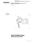
WEB CONTROL PRODUCTS User Manual Sidewall Mount Tension Sensors Type SW FORM NO. L-20361-E-0713 1 FORM NO. L-20361-E-0713 In accordance with Nexen’s established policy of constant product improvement, the specifications contained in this manual are subject to change without notice. Technical data listed in this manual are based on the latest information available at the time of printing and are also subject to change without notice. Technical Support: 800-843-7445 (651) 484-5900 www.nexengroup.com DANGER Read this manual carefully before installation and operation. Follow Nexen’s instructions and integrate this unit into your system with care. This unit should be installed, operated and maintained by qualified personnel ONLY. Improper installation can damage your system, cause injury or death. Comply with all applicable codes. This document is the original, non-translated, version. Conformity Declaration: In accordance with Appendix II B of CE Machinery Directive (2006/42/EC): A Declaration of Incorporation of Partly Completed Machinery evaluation for the applicable EU directives was carried out for this product in accordance with the Machinery Directive. The declaration of incorporation is set out in writing in a separate document and can be requested if required. This machinery is incomplete and must not be put into service until the machinery into which it is to be incorporated has been declared in conformity with the applicable provisions of the Directive. Nexen Group, Inc. 560 Oak Grove Parkway Vadnais Heights, Minnesota 55127 ISO 9001 Certified Copyright 2013 Nexen Group, Inc. FORM NO. L-20361-E-0713 2 Table of Contents General Information------------------------------------------------------------------------------------------------------------------------------1 Installation -----------------------------------------------------------------------------------------------------------------------------------------3 Electrical Connections -------------------------------------------------------------------------------------------------------------------------5 Single Sensor Operation----------------------------------------------------------------------------------------------------------------------5 Troubleshooting-----------------------------------------------------------------------------------------------------------------------------------6 Service Assistance and Repair--------------------------------------------------------------------------------------------------------------7 Parts Replacement-------------------------------------------------------------------------------------------------------------------------------7 Warranty---------------------------------------------------------------------------------------------------------------------------------------------8 3 FORM NO. L-20361-E-0713 GENERAL INFORMATION RECEIVING AND UNPACKING Equipment which will not be installed immediately should be stored in a clean, dry location. Precautions should be taken to prevent moisture, dust, and dirt from accumulating in storage and installation areas. Handle and unpack the equipment carefully. Upon arrival, check the shipment against the packing list. Any damage should be reported immediately to the carrier and to your authorized Nexen Web Handling Distributor. PRECAUTIONS Shipping and Handling The Tension Sensor must be completely surrounded by a soft foam cushion when being transported. The Tension Sensor must be removed when a machine is shipped. Roll Balance and Critical Roll Speed The sensing roll must be dynamically balanced when the roll speed is 300 RPM or greater. The sensing roll must not be driven or have any force applied to it other than by the web. Excessive vibrations can damage the sensors. Critical roll speed = 4.8 x 10⁶ x Shaft O.D. (in RPM) (Shaft Length)2 Even with a balanced roll, a vibration can be set up in a stationary shaft. If this vibration (in cycles per minute) occurs at the harmonic frequency of the shaft, the Tension Sensors can be damaged. To determine the critical roll speed, use the following formula: To assure this problem is avoided, the critical roll speed should at least be 20% above the roll speed attained at maximum web speed. All dimensions are in inches. Overloading Repetitive overloading above the maximum force, shock, or severe overloading should be avoided because it will damage the sensors. SPECIFICATIONS Required Input Impedance of Tension Amplifier 5 K ohms per Tension Sensor (1/2 bridge) 10 K ohms per pair (full bridge) Gage Resistance 95 ohms per gage nominal Excitation Voltage 6.0 VDC or VAC (RMS) maximum Operating Temperature 0o F to 200o F, (-18o C to 93o C) Output Signal at Rated Maximum Force 250mV nominal per Tension Sensor (1/2 bridge) 500mV nominal per Tension Sensor pair (full bridge) FORM NO. L-20361-E-0713 4 DESCRIPTION Nexen Type SW Tension Sensors measure the web tension in unwind, intermediate, and rewind applications. They are appropriate where sidewall mounting of the sensors is required (Figure 1). Type SW Cartridge Nexen Type SW Tension Sensors can be mounted to the machine frame by means of a ring-shaped flange with four mounting bolts or by a single bolt extending through the side frame. The electrical connector is on the side of the sensor cartridge. For an illustration of the sensor and dimensions, see Figure 2 and Table 1. FIGURE 2 FIGURE 1 DIMENSIONS L G L P G C O C 45° H A M (BOLT HOLE DIA.) D H A N (BOLT CIRCLE DIA.) WITH MOUNTING FLANGE WITHOUT MOUNTING FLANGE TABLE 1 A C D G H L M N O P With Flange 1.25 2.26 N/A 2.61 1.77 3.18 13/32 3.25 .58 4.00 Without Flange 1.25 2.26 1/2-13x 0.55DP 2.44 1.77 3.01 N/A N/A N/A N/A NOTES: • All dimensions shown in inches. • Allow 2-1/2 inches clearance for connector, • Maximum roller shaft length = distance between sidewalls - (2xG) 5 FORM NO. L-20361-E-0713 INSTALLATION SELECTION OF SENSOR MOUNTING LOCATION INCORRECT MOUNTING NOTE When selecting a sensor mounting location, keep in mind the tension sensing roll must NOT be mounted where the web wrap can vary. Any change in wrap angle will be sensed by the sensors as a change in tension and indicated as such on the indicator. SW Tension Sensor Idler Roller WEB WRAP ANGLE CHANGES DURING PROCESS Unwind Roll CORRECT MOUNTING SW Tension Sensor Idler Roller Idler Roller Web Wrap Angle Remains Constant Unwind Roll MOUNTING SURFACE PREPARATION The mounting surfaces for the Tension Sensors should be flat and parallel. Prepare the machine frames or mounting surfaces by removing any loose paint, rust, scale, etc. TENSION LOADING DIRECTION The Tension Sensors must be mounted so the applied web force is approximately in line with the cable connector (Figure 3). BISECTOR WITH CABLE CONNECTOR. � FIGURE 3 FORM NO. L-20361-E-0713 6 INSTALLATION PRECAUTIONS CAUTION CAUTION To ensure proper installation and operation of the system, the following steps should be performed in sequence. Failure to do so could seriously damage the Tension Sensors and void the warranty. When disassembling or installing, DO NOT remove the sensor and the tension sensing roll as an assembly–remove the roll first before loosening the sensor mounting bolts. Always install, orient, and firmly bolt down the sensor BEFORE installing the tension sensing roll. DO NOT rotate Tension Sensors (for orientation) with the tension sensing roll installed. Damage may result. TENSION SENSOR INSTALLATION The mounting holes should be drilled so the cable connector is in line with the resultant web force and will not interfere with the four sensor mounting bolts. The cable connector should bisect the web wrap angle. If present mounting holes are to be used or if for some reason new holes cannot be drilled, the split flange can be rotated relative to the sensor body. In order to rotate the split flange, remove the sensor from the machine frame. Loosen the two bolts clamping the split flange to the sensor body. Rotate the split flange to the desired position and then retighten the two clamping bolts. If the cable connector is not lined up with the web force, there will be some loss in sensitivity. SENSING ROLL INSTALLATION After positioning the Tension Sensors, securely tighten the mounting bolts. Check to see the Tension Sensors are parallel and in line. The Tension Sensors are designed to accommodate some frame to frame misalignment. NOTE Misalignment should be less than 1 degree. Remove the sensor shaft caps by removing the four cap screws on each sensor. Mount the tension sensing roll assembly in the Tension Sensors. Clearance between the end of the shaft and the sensor body should be from 1/16-1/64" [1.6-0.4 mm]. FIGURE 4 If shaft bushings are required, use split bushings of the correct length. Do not overhang the sensor I.D. and O.D. Do not use solid bushings. The lengthwise split in the bushing should be directly in line with the gap between the sensor cap and the sensor head. Securely fasten the sensor caps as shown in Figure 4. 7 FORM NO. L-20361-E-0713 ELECTRICAL CONNECTIONS These wiring diagrams are for reference only for use with a dual (full bridge) sensor configuration (See Figure 5). � Use the cables provided with the sensors and the installation wiring diagram supplied with the Nexen tension indicator or controller for making the transducer connections. Make certain the cables do not interfere with the web path and they are away from gearing or other moving parts. Use only the Nexen supplied cables. FIGURE 5 SINGLE SENSOR OPERATION Single sensor operation requires the use of cable # 30517 and is not recommended by Nexen. The tension indicators and controllers will perform best when used with two sensors. For single sensor applications, consult with Nexen Web Technical Support. FORM NO. L-20361-E-0713 8 TROUBLESHOOTING PROBLEM PROBABLE CAUSE SOLUTION Excessive output signal with no load. There may be a high degree of misalignment of the sensor, causing a severe preload. The sensing roll assembly may be excessively heavy. Correct sensor misalignment. The sensing roll should not weigh more than one-half the rated maximum Force of the sensors. Low output signal. Sensor has too large a rated maximum Force for the application. Replace with a lower rated maximum Force sensor or increase the web wrap angle. Output signal fails to increase with added load. Sensors are overloaded and are hitting their mechanical stops. Replace the sensors with ones having a higher rated maximum Force or reduce the load. (This may be accomplished by reducing the web wrap angle and/or using a lighter sensing roll). Wrong polarity of output signal. Sensors may be incorrectly oriented. Rotate sensors 180 degrees. If rotation is impossible, interchange the sensors' output signal leads (green and white) at the tension meter or controller (See Figures 5, 6, and 7). Output signal not linear, zero shifts during operation. Check sensor and tension roll mounting. Check to be sure there is no dirt or foreign matter interfering with the sensor mounting. Tighten all mounting bolts and remove dirt or foreign material. No output signal. Check to see all connections have been made completely. Check for places where the connecting cable might be crimped or cut. Replace cables if necessary. Very high output with no load. Check cable and connector for good connections and check continuity of cable with an ohmmeter. Check for proper wiring to sensor. Check sensor gage resistance as given at room temperature with no load applied (See Table 2). Replace cable, correct wiring, or replace sensor. TABLE 2 SENSOR GAGE RESI STANCE CHECK MEASUREMENT RESI STANCE Pin B to Pin C 195 ohms ±25 ohmx Pin A to Pin B 95 ohms ± 25 ohms Pin A to Pin C Equal to Pin A to Pin B ± 5 ohms 9 FORM NO. L-20361-E-0713 SERVICE ASSISTANCE AND REPAIR For additional service assistance, please obtain the Nexen part number and serial number from the nameplate. Contact your authorized Nexen Distributor. CAUTION Disassembly by improperly trained personnel may result in additional damage to the unit. Contact the factory if repairs become necessary. PARTS REPLACEMENT Contact you local Nexen Distributor for parts availability. This unit is not field serviceable. The only field replaceable component is the cable. SENSOR FORCE (lbs.) PRODUCT NO. 25 50 75 100 150 200 803351 803352 803353 803354 803355 803356 LENGTH (ft.) PRODUCT NO. *16 25 30 50 *30518 15596 15869 15870 CABLE * Cable is included with each SW tension sensor. FORM NO. L-20361-E-0713 10 WARRANTY Warranties Nexen warrants that the Products will (a) be free from any defects in material or workmanship for a period of 12 months from the date of shipment, and (b) will meet and perform in accordance with the specifications in any engineering drawing specifically for the Product that is in Nexen’s current product catalogue, or that is accessible at the Nexen website, or that is attached to this Quotation and that specifically refers to this Quotation by its number, subject in all cases to any limitations and exclusions set out in the drawing. NEXEN MAKES NO OTHER WARRANTY, EXPRESS OR IMPLIED, AND ALL IMPLIED WARRANTIES, INCLUDING WITHOUT LIMITATION, IMPLIED WARRANTIES OF MERCHANTABILITY AND FITNESS FOR A PARTICULAR PURPOSE ARE HEREBY DISCLAIMED. This warranty applies only if: (a) the Product has been installed, used and maintained in accordance with any applicable Nexen installation or maintenance manual for the Product; (b) the alleged defect is not attributable to normal wear and tear; (c) the Product has not been altered, misused or used for purposes other than those for which it was intended; and (d) Buyer has given written notice of the alleged defect to Nexen, and delivered the allegedly defective Product to Nexen, within one year of the date of shipment. Exclusive Remedy The exclusive remedy for the Buyer for any breach of any warranties provided in connection with this agreement will be, at the election of Nexen: (a) repair or replacement with new, serviceably used, or reconditioned parts or products; or (b) issuance of credit in the amount of the purchase price paid to Nexen by the Buyer for the Products. Agent's Authority Buyer agrees that no agent, employee or representative of Nexen has authority to bind Nexen to any affirmation, representation, or warranty concerning the Products other than those warranties expressly set forth herein. Limitation on Nexen’s Liability TO THE EXTENT PERMITTED BY LAW NEXEN SHALL HAVE NO LIABILITY TO BUYER OR ANY OTHER PERSON FOR INCIDENTAL DAMAGES, SPECIAL DAMAGES, CONSEQUENTIAL DAMAGES OR OTHER DAMAGES OF ANY KIND OR NATURE WHATSOEVER, WHETHER ARISING OUT OF BREACH OF WARRANTY OR OTHER BREACH OF CONTRACT, NEGLIGENCE OR OTHER TORT, OR OTHERWISE, EVEN IF NEXEN SHALL HAVE BEEN ADVISED OF THE POSSIBILITY OR LIKELIHOOD OF SUCH POTENTIAL LOSS OR DAMAGE. For all of the purposes hereof, the term "consequential damages" shall include lost profits, penalties, delay damages, liquidated damages or other damages and liabilities which Buyer shall be obligated to pay or which Buyer may incur based upon, related to or arising out of its contracts with its customers or other third parties. In no event shall Nexen be liable for any amount of damages in excess of amounts paid by Buyer for Products or services as to which a breach of contract has been determined to exist. The parties expressly agree that the price for the Products and the services was determined in consideration of the limitation on damages set forth herein and such limitation has been specifically bargained for and constitutes an agreed allocation of risk which shall survive the determination of any court of competent jurisdiction that any remedy herein fails of its essential purpose. Inspection Buyer shall inspect all shipments of Products upon arrival and shall notify Nexen in writing, of any shortages or other failures to conform to these terms and conditions which are reasonably discoverable upon arrival without opening any carton or box in which the Products are contained. Such notice shall be sent within 14 days following arrival. All notifications shall be accompanied by packing slips, inspection reports and other documents necessary to support Buyer's claims. In addition to the foregoing obligations, in the event that Buyer receives Products that Buyer did not order, Buyer shall return the erroneously shipped Products to Nexen within thirty (30) days of the date of the invoice for such Products; Nexen will pay reasonable freight charges for the timely return of the erroneously shipped Products, and issue a credit to Buyer for the returned Products at the price Buyer paid for them, including any shipping expenses that Nexen charged Buyer. All shortages, overages and nonconformities not reported to Nexen as required by this section will be deemed waived. Limitation on Actions No action, regardless of form, arising out of any transaction to which these terms and conditions are applicable may be brought by the Buyer more than one year after the cause of action has accrued. Nexen Group, Inc. 560 Oak Grove Parkway Vadnais Heights, MN 55127 800.843.7445 Fax: 651.286.1099 www.nexengroup.com ISO 9001 Certified 11 FORM NO. L-20361-E-0713