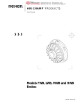
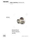
1
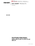
®
MEX (55) 53 63 23 31
DIST. AUTORIZADO QRO (442) 1 95 72 60
MTY (81) 83 54 10 18
[email protected]
AIR CHAMP PRODUCTS
User Manual
SE BRAKE MODELS:
SE-100-1, SE-200-1,
SE-500-1, and SE-1000-1
(i)
FORM NO. L-20084-E-0401
®
MEX (55) 53 63 23 31
DIST. AUTORIZADO QRO (442) 1 95 72 60
MTY (81) 83 54 10 18
[email protected]
In accordance with Nexen’s established policy of constant product improvement, the specifications contained in this
manual are subject to change without notice. Technical data listed in this manual are based on the latest information
available at the time of printing and are also subject to change without notice.
Technical Support:
800-843-7445
(651) 484-5900
www.nexengroup.com
WARNING
Read this manual carefully before installation and operation.
Follow Nexen's instructions and integrate this unit into your system with care.
This unit should be installed, operated and maintained by qualified personnel ONLY.
Improper installation can damage your system or cause injury or death.
Comply with all applicable codes.
Nexen Group, Inc.
560 Oak Grove Parkway
Vadnais Heights, Minnesota 55127
Copyright 2000 Nexen Group, Inc.
ISO 9001 Certified
(ii)
®
MEX (55) 53 63 23 31
DIST. AUTORIZADO QRO (442) 1 95 72 60
MTY (81) 83 54 10 18
[email protected]
TABLE OF CONTENTS
Introduction ---------------------------------------------------------------------------------------------------------------------------------------- 1
Installation ---------------------------------------------------------------------------------------------------------------------------------------- 2
Air Connections --------------------------------------------------------------------------------------------------------------------------------- 3
Lubrication ----------------------------------------------------------------------------------------------------------------------------------------- 3
Troubleshooting---------------------------------------------------------------------------------------------------------------------------------- 4
Parts Replacement ----------------------------------------------------------------------------------------------------------------------------- 4
Replacement Parts ----------------------------------------------------------------------------------------------------------------------------- 7
Parts List / SE-100-1 and SE-200-1 --------------------------------------------------------------------------------------------------- 7
Parts List / SE-500-1 and SE-1000-1 ------------------------------------------------------------------------------------------------- 8
Warranties --------------------------------------------------------------------------------------------------------------------------------------- 10
(iii)
®
MEX (55) 53 63 23 31
DIST. AUTORIZADO QRO (442) 1 95 72 60
MTY (81) 83 54 10 18
[email protected]
INTRODUCTION
Nexen's Air Champ Spring Engaged Brakes offer worker protection on conveyors, hoists, and other equipment where
fast, dependable stopping may prevent physical injury.
SE Brakes also protect equipment with controlled engagement where sudden stops may damage valuable equipment.
When power to the control valve is lost, or air is exhausted, springs engage the SE Brake, and the load is held in a stable
position. Nexen's SE Brake also incorporates a manual release, which is used to disengage the brake if no air pressure is
available.
Read this manual carefully, making full use of its explanations and instructions. The “Know How” of safe, continuous,
trouble-free operation depends on the degree of your understanding of the system and your willingness to keep all
components in proper operating condition. Pay particular attention to all NOTES, CAUTIONS, and WARNINGS to avoid
the risk of personal injury or property damage. It is important to understand that these NOTES, CAUTIONS, and
WARNINGS are not exhaustive. Nexen cannot possibly know or evaluate all conceivable methods in which service may
be performed, or the possible hazardous consequences of each method. Accordingly, anyone who uses a procedure
that is not recommended by Nexen must first satisfy themselves that neither their safety
or the safety of the product will be jeopardized by the service method selected.
Do not run the SE Brake in disengaged position (locking pin pulled out). Always manually
reengage the SE Brake before starting motor.
FORM NO. L-20084-E-0401
1
®
MEX (55) 53 63 23 31
DIST. AUTORIZADO QRO (442) 1 95 72 60
MTY (81) 83 54 10 18
[email protected]
INSTALLATION
MOTOR SHAFT MOUNTED SE BRAKE
Opposite Drive End on Double “C” Faced Motor (See
Figure 1)
1. Insert the Key (Item 37) into shaft keyway.
2. Slide the SE Brake onto motor shaft and secure with
mounting bolts.
FIGURE 1
SHAFT MOUNTED SE BRAKE
with Torque Arm (See Figure 2)
1. Insert the Key (Item 37) into the shaft keyway.
Torque
Arm
2. Slide the SE Brake onto the shaft.
3. Retain the Key with the set collar.
FIGURE 2
SE BRAKE MOUNTED BETWEEN A MOTOR AND
GEAR REDUCER (See Figure 3)
1. Insert the Key (Item 37) into the shaft keyway.
2. Slide the SE Brake onto motor shaft and secure it
with mounting bolts.
Adaptor
Shaft
3. Insert the first Key into Adaptor Shaft and insert
Adaptor Shaft into the SE Brake.
FIGURE 3
4. Insert the second key into Adaptor Shaft; then, insert
Adaptor Shaft into reducer, and bolt the SE Brake
and motor to gear reducer.
Output
Unit
MOUNTING AN OUTPUT UNIT (See Figure 4)
An Output Unit can be mounted to the SE Brake when a
drive through arrangement is desired. The Output Unit
can then be used to mount a sheave, sprocket, or other
desired drive.
Mounting Foot
(Prod. No. 883000)
FIGURE 4
With the Output Unit attached, the SE Brake may be foot
mounted to provide a free standing drive through
arrangement (Models SE-100-1 and SE-200-1 only).
2
FORM NO. L-20084-E-0401
®
MEX (55) 53 63 23 31
DIST. AUTORIZADO QRO (442) 1 95 72 60
MTY (81) 83 54 10 18
[email protected]
AIR CONNECTIONS
TABLE 1
Nexen's SE Brakes engage when the air supply is
exhausted by the control valve or when there is a loss of
air supply, and engage when air pressure is applied (See
Table 1).
MI NI MUM DI SENGAGEMENT AI R PRESSURES
For maximum performance, mount the control valve as
close to the SE Brake as possible. A Hose Assembly
(Item 36) is supplied.
SE Brake engagement is controlled by a Restrictor Valve
(Item 41). For faster response, remove the Restrictor
Valve. If maximum response time is needed, install a
Quick Exhaust Valve in place of the Restrictor Valve.
LUBRICATION
The most effective and economical way to lubricate SE
Brakes is with an airline lubricator. Available from Nexen,
the lubricator injects oil into the pressurized air, forcing a
constant oil mist into the air chamber.
Lubricator drip rate is properly set when one drop of oil
forms in the lubricator sight gage after the SE Brake has
cycled twenty times. Locate the lubricator above and
within ten feet of the SE Brake.
NOTE: Use a low viscosity petroleum base oil, such as
SAE 10. Do not use synthetic lubricant.
When a lubricator is used, cycle the SE Brake
periodically to allow oil from the lubricator to enter the SE
Brake air chamber.
Bearings in SE Brakes are prelubricated and sealed, and
therefore require no further lubrication.
FORM NO. L-20084-E-0401
3
MODEL
AI R PRESSURE
SE-100
40 PSI
SE-200
50 PSI
SE-500
30 PSI
SE-1000
50 PSI
®
MEX (55) 53 63 23 31
DIST. AUTORIZADO QRO (442) 1 95 72 60
MTY (81) 83 54 10 18
[email protected]
TROUBLESHOOTING
SYMPTOM
CAUSE
SOLUTION
Failure to Engage.
Air not being exhausted due to Control Valve
malfunction.
Replace Control Valve.
Broken Engagement Springs.
Replace Engagement Springs.
Internal contamination or corrosion.
Align exhaust port to the six o'clock down position to
allow condensation to drain out of exhaust port.
Low or lack of air pressure.
Check for Control Valve malfunction; replace if
defective.
Failure to Disengage.
Check for leaks in air lines and replace if defective.
Friction lock due to lack of lubrication on Hub
Spline or in Air Chamber.
Lubricate Hub Spline with NEVER-SEEZ®.
Use an Air Line Lubricator.
Loss of Torque.
Internal contamination or corrosion.
Align exhaust port to the six o'clock down position to
allow condensation to drain out of exhaust port.
Damaged Locking Pin.
Replace Locking Pin.
Worn or dirty Friction Facings
Replace Friction Facings.
PARTS REPLACEMENT
SE DISASSEMBLY
1. Apply air pressure to disengage the SE Brake.
2. Remove the Retaining Ring (Item 14) (See Figure 5).
23, 24
14
Special attention should be exercised when
working with retaining rings. Always wear
safety goggles when working with spring or
tension loaded fasteners or devices.
FIGURE 5
3. Exhaust air pressure.
Air Chamber
Housing
4. Slowly, and in a cross pattern, remove Socket Head
Cap Screws (Item 23), and Lockwashers (Item 24)
(See Figure 5).
Internal
Assembly
5. Slide the Air Chamber Housing (Item 2) off internal
assembly of the SE Brake (See Figure 6).
FIGURE 6
4
FORM NO. L-20084-E-0401
®
MEX (55) 53 63 23 31
DIST. AUTORIZADO QRO (442) 1 95 72 60
MTY (81) 83 54 10 18
[email protected]
FRICTION FACING REPLACEMENT
1. Remove the Friction Plates (Item 5) and Friction
Facings (Item 7) (See Figure 6).
7
5
NOTE: SE Brakes Models SE-100-1 , and SE-200-1
have one Friction Plate and Friction Facing,
while Models SE-500-1 and SE-1000-1
have three Friction Plates and Friction
Facings.
FIGURE 7
2. Install the new Friction Facings (Item 7).
O-RINGS (ITEMS 12 and 13).
1. Remove old O-rings (Items 12 and 13) (See Figure 8).
12
2. Clean O-ring contact surfaces of the Piston (Item 3)
and Air Chamber Housing (Item 2) with fresh safety
solvent.
13
3. Lubricate new O-rings (Items 12 and 13) and O-ring
contact surfaces with fresh O-ring lubricant.
FIGURE 8
4. Install new O-rings (Items 12 and 13).
BEARINGS (ITEMS 21 and 22).
Engagement Spring
(Item 19)
1. Slide Friction Disc (Item 6) and Piston (Item 3) off
Hub (Item 1) (See Figure 9).
Friction Disc (Item 6)
and Piston (Item 3)
NOTE: Inspect Engagement Springs (Item 19) for
signs of wear or fatigue. Replace if worn or
if signs of fatigue exist (See Figure 9).
2. Remove Retaining Ring (Item 15) and press Friction
Disc (Item 6) out of Bearing (Item 21) (See Figure 10).
Hub
(Item 1)
FIGURE 9
CAUTION
Special attention must be exercised
when working with retaining rings.
Always wear safety goggles when
working with spring or tension loaded
fasteners or devices.
3
21
16
15
6
3. Remove the Retaining Ring (Item 16) and press the
Bearing (Item 21) out of the Piston (Item 3) (See
Figure 10).
4. Clean the bearing bore of the Piston (Item 3) with
fresh safety solvent.
FORM NO. L-20084-E-0401
FIGURE 10
5
®
MEX (55) 53 63 23 31
DIST. AUTORIZADO QRO (442) 1 95 72 60
MTY (81) 83 54 10 18
[email protected]
5. Remove the Retaining Ring (Item 14) on Models SE100-1 and SE-200-1, or (Item 33) on Models SE500-1 and SE-1000-1 (See Figures 11 & 12).
14
1
6. Press the Hub (Item 1) out of the Spring Housing
(Item 4) and Bearing (Item 22) (See Figures 11 & 12).
Spring Housing
and Bearing
7. Remove the Retaining Ring (Item 17) (See Figure 13).
FIGURE 11
Models SE-100-1 & SE-200-1
8. Press the Bearing (Item 22) out of the Spring
Housing (Item 4) (See Figure 13).
33
9. Clean the bearing bore of the Spring Housing (Item
4)with fresh safety solvent.
10. Apply Loctite® 601, or equivalent, to the outer races
of the new Bearings (Items 21 and 22).
1
11. Carefully align the O.D. of the Bearing (Item 22) with
the bore of the Spring Housing (Item 4) and press
the new Bearing into the Spring Housing.
FIGURE 12
Models SE-500-1 & SE-1000-1
12. Carefully align the O.D. of the Bearing (Item 21) with
the bore of the Piston (Item 3) and press the new
Bearing into the Piston.
Spring Housing
and Bearing
13. Reverse Steps 1-7 to reassemble the internal brake
components.
17
BRAKE REASSEMBLY
22
1. Slide the Air Chamber Housing (Item 2) onto the
Internal Assembly (See Figure 14).
FIGURE 13
4
2. Using Cap Screws (Item 23), secure the SE Brake
halves together (See Figure 15).
Air Chamber
Housing
3. Alternately and evenly tighten the Cap Screws (Item
23) to 8 Ft. Lbs. [10.8 N•m].
4. Apply air pressure to disengage the SE Brake.
Internal
Assembly
5. Install Retaining Ring (Item 14) (See Figure 15).
FIGURE 14
CAUTION
Special attention must be exercised
when working with retaining rings.
Always wear safety goggles when
working with spring or tension loaded
fasteners or devices.
23
14
6. Exhaust air pressure.
FIGURE 15
6
FORM NO. L-20084-E-0401
®
MEX (55) 53 63 23 31
DIST. AUTORIZADO QRO (442) 1 95 72 60
MTY (81) 83 54 10 18
[email protected]
REPLACEMENT PARTS
When ordering replacement parts, specify model
designation, item number, part description, and quantity.
Purchase replacement parts through your local Nexen
Distributor.
The item or balloon number for all Nexen products is
used for part identification on all product parts lists,
product price lists, unit assembly drawings, bills of
materials, and instruction manuals.
PARTS LIST / SE-100-1 AND SE-200-1
10
8
20
9
21
15
16
6
2
17
40
7
5
23
11
18
14
19
1
22
4
13
14
12
3
FIGURE 16
1
ITEM
DESCRIPTION
QTY
ITEM
DESCRIPTION
QTY
1
2
3
4
5
6
71
8
9
10
11
121
131
14
15
16
Hub
Air Chamber Housing
Piston
Spring Housing
Friction Plate
Friction Disc
Friction Facing
Locking Pin Retainer
Locking Pin
Locking Pin Handle
Splined Sleeve
O-ring Seal (Large)
O-ring Seal (Small)
Retaining Ring
Retaining Ring
Retaining Ring
1
1
1
1
1
1
1
1
1
1
1
1
1
2
1
1
17
18
191
20
211
221
23
24
35
36
37
38
39
40
41
42
Retaining Ring
Retaining Ring
Engagement Spring
Locking Pin Spring
Bearing
Bearing
Cap Screws
Lockwashers
Plug (Not Shown)
Hose Assembly (Not Shown)
Hub Key (Not Shown)
Cap Screws (Not Shown)
Lockwashers (Not Shown)
Spring Pin
Restrictor Valve (Optional, Not Shown)
Air House Coupling (Not Shown)
1
1
8
1
1
1
4
4
1
1
1
4
4
1
1
1
Denotes Repair Kit Items
FORM NO. L-20084-E-0401
7
®
MEX (55) 53 63 23 31
DIST. AUTORIZADO QRO (442) 1 95 72 60
MTY (81) 83 54 10 18
[email protected]
PARTS LIST / SE-500-1 AND SE-1000-1
10
21
8
15
16
20
6
9
33
23
2
7
5
7
19
5
7
40
5
17
11
22
18
14
4
1
12
FIGURE 17
1
13
3
ITEM
DESCRIPTION
QTY
ITEM
DESCRIPTION
QTY
1
2
3
4
5
6
71
8
9
10
11
121
131
14
15
16
Hub
Air Chamber Housing
Piston
Spring Housing
Friction Plate
Friction Disc
Friction Facing
Locking Pin Retainer
Locking Pin
Locking Pin Handle
Splined Sleeve
O-ring Seal (Large)
O-ring Seal (Small)
Retaining Ring
Retaining Ring
Retaining Ring
1
1
1
1
3
1
3
1
1
1
1
1
1
1
1
1
17
18
191
20
211
221
23
24
33
35
36
37
38
39
40
41
Retaining Ring
Retaining Ring
Engagement Spring
Locking Pin Spring
Bearing
Bearing
Cap Screws
Lockwashers
Retaining Ring
Plug (Not Shown)
Hose Assembly (Not Shown)
Hub Key (Not Shown)
Cap Screws (Not Shown)
Lockwashers (Not Shown)
Spring Pin
Restrictor Valve (Optional, Not Shown)
1
1
8
1
1
1
4
4
1
1
1
1
4
4
1
1
Denotes Repair Kit Items
8
FORM NO. L-20084-E-0401
®
MEX (55) 53 63 23 31
DIST. AUTORIZADO QRO (442) 1 95 72 60
MTY (81) 83 54 10 18
[email protected]
OUTPUT DRIVE UNIT
ITEM
DESCRIPTION
QTY
25
26
27
28
29
30
31
32
34
Shaft
Bearing Flange
Bearing
Retaining Ring
Key
Key
Cap Screw
Lockingwasher (Not Shown)
Retaining Ring
1
1
1
2
2**
**
4
4
1
34
29
30
26
31
28
25
28
27
** Qty.1 / SE-100-1 and SE-200-1
FIGURE 18
OUTPUT DRIVE UNIT
ACCESSORI ES
REPAI R KITS
MODEL
PRODUCT NUMBER
SE-100-1
808400
SE-200-1
808500
SE-500-1
812700
SE-1000-1
812800
FORM NO. L-20084-E-0401
DESCRI PTION
PRODUCT
NUMBE R
Output Unit
932600
932700
933000
933000
933100
SE-100
SE-200
SE-500
SE-1000
Adaptor Shaft
805700
805800
812500
812600
SE-100 & SE-200
SE-500 & SE-1000
Torque Arm
932900
933200
SE-100 & SE-200
'L' Mounting
883000
MODEL
SE-100
SE-200
SE-500
SE-1000
9
®
MEX (55) 53 63 23 31
DIST. AUTORIZADO QRO (442) 1 95 72 60
MTY (81) 83 54 10 18
[email protected]
WARRANTIES
Warranties
Nexen warrants that the Products will be free from any defects in material or workmanship for a period of 12 months
from the date of shipment. NEXEN MAKES NO OTHER WARRANTY, EXPRESS OR IMPLIED, AND ALL IMPLIED
WARRANTIES, INCLUDING WITHOUT LIMITATION, IMPLIED WARRANTIES OF MERCHANTABILITY AND
FITNESS FOR A PARTICULAR PURPOSE ARE HEREBY DISCLAIMED. This warranty applies only if (a) the Product
has been installed, used and maintained in accordance with any applicable Nexen installation or maintenance manual
for the Product; (b) the alleged defect is not attributable to normal wear and tear; (c) the Product has not been altered,
misused or used for purposes other than those for which it was intended; and (d) Buyer has given written notice of the
alleged defect to Nexen, and delivered the allegedly defective Product to Nexen, within one year of the date of
shipment.
Exclusive Remedy
The exclusive remedy of the Buyer for any breach of the warranties set out above will be, at the sole discretion of Nexen,
a repair or replacement with new, serviceably used or reconditioned Product, or issuance of credit in the amount of the
purchase price paid to Nexen by the Buyer for the Products.
Limitation of Nexen’s Liability
TO THE EXTENT PERMITTED BY LAW NEXEN SHALL HAVE NO LIABILITY TO BUYER OR ANY OTHER PERSON
FOR INCIDENTAL DAMAGES, SPECIAL DAMAGES, CONSEQUENTIAL DAMAGES OR OTHER DAMAGES OF
ANY KIND OR NATURE WHATSOEVER, WHETHER ARISING OUT OF BREACH OF WARRANTY OR OTHER
BREACH OF CONTRACT, NEGLIGENCE OR OTHER TORT, OR OTHERWISE, EVEN IF NEXEN SHALL HAVE
BEEN ADVISED OF THE POSSIBILITY OR LIKELIHOOD OF SUCH POTENTIAL LOSS OR DAMAGE. For all of
the purposes hereof, the term “consequential damages” shall include lost profits, penalties, delay images, liquidated
damages or other damages and liabilities which Buyer shall be obligated to pay or which Buyer may incur based upon,
related to or arising out of its contracts with its customers or other third parties. In no event shall Nexen be liable for
any amount of damages in excess of amounts paid by Buyer for Products or services as to which a breach of contract
has been determined to exist. The parties expressly agree that the price for the Products and the services was
determined in consideration of the limitation on damages set forth herein and such limitation has been specifically
bargained for and constitutes an agreed allocation of risk which shall survive the determination of any court of
competent jurisdiction that any remedy herein fails of its essential purpose.
Limitation of Damages
In no event shall Nexen be liable for any consequential, indirect, incidental, or special damages of any nature whatsoever, including without limitation, lost profits arising from the sale or use of the Products.
Warranty Claim Procedures
To make a claim under this warranty, the claimant must give written notice of the alleged defect to whom the Product
was purchased from and deliver the Product to same within one year of the date on which the alleged defect first
became apparent.
Nexen Group, Inc.
560 Oak Grove Parkway
Vadnais Heights, MN 55127
800.843.7445
Fax: 651.286.1099
www.nexengroup.com
ISO 9001 Certified
10
FORM NO. L-20084-E-0401