1
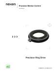
WEB CONTROL PRODUCTS
User Manual
Electro-Pneumatic Transducer
EN50
1
FORM NO. L-20313-E-0612
In accordance with Nexen’s established policy of constant product improvement, the specifications contained in this
manual are subject to change without notice. Technical data listed in this manual are based on the latest information
available at the time of printing and are also subject to change without notice.
Technical Support: 800-843-7445
(651) 484-5900
www.nexengroup.com
DANGER
Read this manual carefully before installation and operation.
Follow Nexen’s instructions and integrate this unit into your
system with care. This unit should be installed, operated and
maintained by qualified personnel ONLY. Improper installation
can damage your system, cause injury or death. Comply with
all applicable codes.
This document is the original, non-translated, version.
Conformity Declaration: In accordance with Appendix II B of CE Machinery Directive (2006/42/EC):
A Declaration of Incorporation of Partly Completed Machinery evaluation for the applicable EU directives
was carried out for this product in accordance with the Machinery Directive. The declaration of incorporation
is set out in writing in a separate document and can be requested if required.
This machinery is incomplete and must not be put into service until the machinery into which it is to be
incorporated has been declared in conformity with the applicable provisions of the Directive.
Nexen Group, Inc.
560 Oak Grove Parkway
Vadnais Heights, Minnesota 55127
ISO 9001 Certified
Copyright 2012 Nexen Group, Inc.
FORM NO. L-20313-E-0612
2
Table of Contents
Introduction------------------------------------------------------------------------------------------------------------ 4
Installation------------------------------------------------------------------------------------------------------------- 4
Pneumatic Connections-------------------------------------------------------------------------------------------- 5
Electrical Connections---------------------------------------------------------------------------------------------- 5
Calibration and Adjustment---------------------------------------------------------------------------------------- 6
Maintenance---------------------------------------------------------------------------------------------------------- 7
Troubleshooting------------------------------------------------------------------------------------------------------ 7
Specifications--------------------------------------------------------------------------------------------------------- 8
Warranty--------------------------------------------------------------------------------------------------------------- 9
3
FORM NO. L-20313-E-0612
INTRODUCTION
The Nexen EN50 Electro-Pneumatic Transducer
converts a 4–20 mA DC or 0–10VDC input signal to
a pneumatic output pressure. The output pressure is
linearly proportional to the input signal.
INSTALLATION
Mount the Nexen EN50 vertically, with electrical
connections above pneumatic ports, on a flat surface
using the two 10-32 tapped mounting holes located on
the Transducer or use the Mounting Plate to mount the
Transducer to a flat surface or to a 11/2'' diameter pipe
(See Figure 1). Mounting EN50 on an incline will require
re-calibration. (See CALIBRATION AND ADJUSTMENT
SECTION).
NOTE: The Breakaway Tabs on the Mounting Plate
may be removed when the Mounting Plate is used
with pipe clamps (See Figure 1).
UP
1/4 NPT Ports
FIGURE 1
FORM NO. L-20313-E-0612
4
PNEUMATIC CONNECTIONS
NOTE: Nexen's EN50 requires clean, pressure
regulated air for maximum performance and long
life. Your Nexen Distributor carries filters and
regulators specifically designed to operate with
Nexen products.
ZERO
SPAN
A Pre-filter (rated at 5.0 micron or less) removes
large particles from the air supply. The Final Filter
(rated at 0.1 micron or less) is used to filter the air
before it enters the Nexen EN50.
OUT
Clean all pipelines to remove dirt and scale before
installation. If you use a pipe compound when
installing the pipe or tube fittings into the Nexen
EN50, use a Teflon dope as a sealant.
IN
OUT
IN
Make air connections
to bottom block only.
FIGURE 2
1. Apply a minimum amount of pipe sealant
compound to the male threads of the fitting only;
then, start at the third thread back and work away
from the end of the fitting to avoid the possibility of
contaminating the Nexen EN50.
NOTE: The inlet and outlet ports are labeled on the
side of the EN50. User connections should be made
to the inlet and outlet ports located in the bottom of
the valve body only (See Figure 2).
2. Install the Nexen EN50 in the air line and securely
tighten the connections.
3. Install the plugs supplied with the Nexen EN50 in
all unused ports.
ELECTRICAL CONNECTIONS
Refer to Figure 3 for electrical connections.
Figure 3
5
FORM NO. L-20313-E-0612
CALIBRATION AND ADJUSTMENT
NOTE: EN50 is calibrated prior to shipping and normally does not require calibration after delivery. If
calibration or adjustment is deemed necessary, only do so after EN50 has been mounted in its operating
position.
FULL RANGE OPERATION
Forward Acting Mode Adjustment
1. Turn the Zero Adjustment Screw clockwise to
increase pressure and counter-clockwise to
decrease pressure, apply the minimum input signal
(i.e., 4 mA or 0 V) and adjust the Zero Adjustment
Screw for minimum output pressure (i.e., 0 psi).
2. Turn the Span Adjustment Screw clockwise to
increase pressure and counter-clockwise to
decrease pressure, apply the maximum input
signal (i.e., 20 mA or 10 V) and adjust the Span
Adjustment Screw for maximum output pressure
(See SPECIFICATIONS).
Zero Adjustment
ZERO
SPAN
3. Repeat Zero and Span calibration (Steps 1 and 2)
until the desired output range is obtained.
Span
Adjustment
Reverse Acting Mode Adjustment
NOTE: The input signal to the red and black leads
must be reversed when reversing the action.
1. Turn the Zero Adjustment Screw clockwise to
increase pressure and counter-clockwise to
decrease pressure, apply the minimum input
signal (i.e., 4 mA or 0 V) and adjust the Zero
Adjustment Screw for maximum output pressure
(See SPECIFICATIONS).
OUT
2. Turn the Span Adjustment Screw clockwise to
increase pressure and counter-clockwise to
decrease pressure, apply the maximum input
signal (i.e., 20 mA or 10 V) and adjust the Span
Adjustment Screw for minimum output pressure
(i.e., 0 psi).
Figure 4
3. Repeat Zero and Span calibration (Steps 1 and 2)
until the desired output range is obtained.
SPLIT RANGE OPERATION
All Nexen EN50s have the capability to be split or set
for any output in the range as long as the Output Span
is equal to or greater than the minimum Span shown in
the SPECIFICATIONS.
FORM NO. L-20313-E-0612
6
IN
MAINTENANCE
Cleaning the Orifice is the only maintenance required
for the Nexen EN50.
Nexen
EN50
NOTE: It is not necessary to remove the Nexen EN50
from the air line.
1. Shut off the valve supplying air to the Nexen EN50.
2. Remove the Orifice from the Nexen EN50 (See
Figure 5).
Orifice
3. Clean the Orifice with alcohol; then, dry the Orifice
with compressed air (See Figure 5).
NOTE: The Orifice must be completely dry before
reinstalling it into the Nexen EN50.
Figure 5
4. Reinstall the Orifice into the Nexen EN50 (See
Figure 5).
TROUBLESHOOTING
WARNING
Failure of the Nexen EN50 could result
in output pressure increasing to supply
pressure, possibly causing personal injury
or damage to the equipment.
Symptom
No Output
Leakage
Probable Cause
Solution
Faulty supply pressure
Verify that supply pressure is
correct.
Clogged orifice
Clean the orifice.
Improper air line connections.
Inspect and correct all air line
connections.
Incorrect Zero and Span adjustment Perform Zero and Span adjustment.
Low or improper Span Adjustment
Erratic operation
Low supply pressure
Verify that supply pressure is
correct.
Output leakage
Inspect and correct all air line
connections.
Improper DC signal
Check all electrical connections and
verify that DC signal polarity and
level is correct.
Loose wires or electrical
connections
Inspect all wires and electrical
connections and replace damaged
wires or repair faulty electrical
connections.
Liquid in the air supply
Purge liquid from the air supply and
use the recommended filter.
Dirt in the magnet gap
Inspect and clean the magnet gap.
7
FORM NO. L-20313-E-0612
SPECIFICATIONS
FUNCTIONAL
SPECI FICATIONS
EN50-15
EN50-6 0
EN50-8 5
EN50-85V
0-15 psig
[0-105 kPa]
0-60 psig
[0-420 kPa]
0-85 psig
[0-595 kPa]
0-85 psig
[0-595 kPa]
Supply Pressure
20-150 psig
[140-1050 kPa]
65-150 psig
[455-1050 kPa]
90-150 psig
[630-1050 kPa]
90-150 psig
[630-1050 kPa]
Effects on Output
.5 psig [4 kPa] @
25 psig [175 kPa]
1.0 psig [7 kPa] @
25 psig [175 kPa]
1.5 psig [10.5 kPa] @
25 psig [175 kPa]
1.5 psig [10.5 kPa] @
25 psig [175 kPa]
12.5 [84 ]
25 [175]
50 [350]
50 [350]
12.0 (0.34 m³/ Hr)
13.0 (0.36 m³/ Hr)
6.0 (0.48 m³/ Hr)
6.0 (0.48 m³/ Hr)
Output Range
Minimum Span
Air Consumption (SCFH)
Flow Rate (SCFM)
11 SCFM (3.19 m / Hr) @ 150 psig [1050 kPa] and 9 psig [63kPa] output
3
Impedance/ Input Signal
PERFORMANCE
SPECI FICATIONS
250 Ohms
256 Ohms
270 Ohms
EN50-15
EN50-6 0
EN50-8 5
893 Ohms
EN50-85V
Independent Linearity (%FS)
± 0.7 5
± 1.0
± 1.0
± 1.0
Hysteresis and Repeatability
< 1.0% FS @ 35 psig
supply
< 1.0% FS @ 65 psig
supply
< 1.0% FS @125 psig
supply
< 1.0% FS @125 psig
supply
-20° F to + 150° F [-30° C to + 65° C]
Temperature Range
Materials of Construction
Body and Housing..............................................................................................................................................................Aluminum
Orifice............................................................................................................................................................................SapphireTrim
Trim............................................................................................................................Stainless Steel, Brass, and Zinc Plated Steel
PRODUCT NUMBERS
EN50
FILTERS
Model
Number
Product
Number
Air Output
Signal
Output
EN50-15
964229
0-15 psi
4-20 mA
EN50-60
964230
0-60 psi
4-20 mA
EN50-85
964231
0-85 psi
4-20 mA
EN50-85V
964232
0-85 psi
0-10 mA
FORM NO. L-20313-E-0612
8
Description
Product Number
3 Micron and .1 Micron
Combination Filter
912142
WARRANTY
Warranties
Nexen warrants that the Products will (a) be free from any defects in material or workmanship for a period of 12 months
from the date of shipment, and (b) will meet and perform in accordance with the specifications in any engineering drawing
specifically for the Product that is in Nexen’s current product catalogue, or that is accessible at the Nexen website, or that is
attached to this Quotation and that specifically refers to this Quotation by its number, subject in all cases to any limitations
and exclusions set out in the drawing. NEXEN MAKES NO OTHER WARRANTY, EXPRESS OR IMPLIED, AND ALL
IMPLIED WARRANTIES, INCLUDING WITHOUT LIMITATION, IMPLIED WARRANTIES OF MERCHANTABILITY AND
FITNESS FOR A PARTICULAR PURPOSE ARE HEREBY DISCLAIMED. This warranty applies only if: (a) the Product
has been installed, used and maintained in accordance with any applicable Nexen installation or maintenance manual
for the Product; (b) the alleged defect is not attributable to normal wear and tear; (c) the Product has not been altered,
misused or used for purposes other than those for which it was intended; and (d) Buyer has given written notice of the
alleged defect to Nexen, and delivered the allegedly defective Product to Nexen, within one year of the date of shipment.
Exclusive Remedy
The exclusive remedy for the Buyer for any breach of any warranties provided in connection with this agreement will be,
at the election of Nexen: (a) repair or replacement with new, serviceably used, or reconditioned parts or products; or (b)
issuance of credit in the amount of the purchase price paid to Nexen by the Buyer for the Products.
Agent's Authority
Buyer agrees that no agent, employee or representative of Nexen has authority to bind Nexen to any affirmation,
representation, or warranty concerning the Products other than those warranties expressly set forth herein.
Limitation on Nexen’s Liability
TO THE EXTENT PERMITTED BY LAW NEXEN SHALL HAVE NO LIABILITY TO BUYER OR ANY OTHER PERSON
FOR INCIDENTAL DAMAGES, SPECIAL DAMAGES, CONSEQUENTIAL DAMAGES OR OTHER DAMAGES OF
ANY KIND OR NATURE WHATSOEVER, WHETHER ARISING OUT OF BREACH OF WARRANTY OR OTHER
BREACH OF CONTRACT, NEGLIGENCE OR OTHER TORT, OR OTHERWISE, EVEN IF NEXEN SHALL HAVE
BEEN ADVISED OF THE POSSIBILITY OR LIKELIHOOD OF SUCH POTENTIAL LOSS OR DAMAGE. For all of
the purposes hereof, the term "consequential damages" shall include lost profits, penalties, delay damages, liquidated
damages or other damages and liabilities which Buyer shall be obligated to pay or which Buyer may incur based upon,
related to or arising out of its contracts with its customers or other third parties. In no event shall Nexen be liable for any
amount of damages in excess of amounts paid by Buyer for Products or services as to which a breach of contract has
been determined to exist. The parties expressly agree that the price for the Products and the services was determined
in consideration of the limitation on damages set forth herein and such limitation has been specifically bargained for and
constitutes an agreed allocation of risk which shall survive the determination of any court of competent jurisdiction that
any remedy herein fails of its essential purpose.
Inspection
Buyer shall inspect all shipments of Products upon arrival and shall notify Nexen in writing, of any shortages or other failures
to conform to these terms and conditions which are reasonably discoverable upon arrival without opening any carton
or box in which the Products are contained. Such notice shall be sent within 14 days following arrival. All notifications
shall be accompanied by packing slips, inspection reports and other documents necessary to support Buyer's claims. In
addition to the foregoing obligations, in the event that Buyer receives Products that Buyer did not order, Buyer shall return
the erroneously shipped Products to Nexen within thirty (30) days of the date of the invoice for such Products; Nexen
will pay reasonable freight charges for the timely return of the erroneously shipped Products, and issue a credit to Buyer
for the returned Products at the price Buyer paid for them, including any shipping expenses that Nexen charged Buyer.
All shortages, overages and nonconformities not reported to Nexen as required by this section will be deemed waived.
Limitation on Actions
No action, regardless of form, arising out of any transaction to which these terms and conditions are applicable may be
brought by the Buyer more than one year after the cause of action has accrued.
Nexen Group, Inc.
560 Oak Grove Parkway
Vadnais Heights, MN 55127
800.843.7445
Fax: 651.286.1099
www.nexengroup.com
ISO 9001 Certified
9
FORM NO. L-20313-E-0612