1
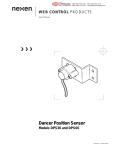
LINEAR MOTION CONTROL PRODUCTS
User Manual
Rail Brake
Generation II
RB15, RB20, RB25, RB30, RB35, RB45,
RB55* and RB65*
*RB55 and RB65 are currently not
compliant.
FORM NO. L-21326-F-0815
In accordance with Nexen’s established policy of constant product improvement, the specifications contained in this
manual are subject to change without notice. Technical data listed in this manual are based on the latest information
available at the time of printing and are also subject to change without notice.
Technical Support: 800-843-7445
(651) 484-5900
www.nexengroup.com
DANGER
Read this manual carefully before installation and operation.
Follow Nexen’s instructions and integrate this unit into your
system with care. This unit should be installed, operated and
maintained by qualified personnel ONLY. Improper installation
can damage your system, cause injury or death. Comply with
all applicable codes.
This document is the original, non-translated, version.
Conformity Declaration: In accordance with Appendix II B of CE Machinery Directive (2006/42/EC):
A Declaration of Incorporation of Partly Completed Machinery evaluation for the applicable EU directives was carried
out for this product in accordance with the Machinery Directive. The declaration of incorporation is set out in writing in
a separate document and can be requested if required.
This machinery is incomplete and must not be put into service until the machinery into which it is to be incorporated
has been declared in conformity with the applicable provisions of the Directive.
Nexen Group, Inc.
560 Oak Grove Parkway
Vadnais Heights, Minnesota 55127
ISO 9001 Certified
Copyright 2015 Nexen Group, Inc.
FORM NO. L-21326-F-0815
2
Table of Contents
General Specifications-------------------------------------------------------------------------------------------------------------------------4
General Safety Precautions------------------------------------------------------------------------------------------------------------------4
Installation -----------------------------------------------------------------------------------------------------------------------------5
Required Tools-------------------------------------------------------------------------------------------------------------------5
Air Connections-----------------------------------------------------------------------------------------------------------------5
Accessories----------------------------------------------------------------------------------------------------------------------5
Mounting on a Rail-------------------------------------------------------------------------------------------------------------6
Alignment Verification---------------------------------------------------------------------------------------------------------7
Friction Facing Gap Adjustment------------------------------------------------------------------------------------------7
Friction Facing Replacement----------------------------------------------------------------------------------------------------8
Service Restrictions ---------------------------------------------------------------------------------------------------------------8
Warranty -------------------------------------------------------------------------------------------------------------------------------9
3
FORM NO. L-21326-F-0815
GENERAL SPECIFICATIONS
Specifications
Holding Force:
Up to 3400 N (764 lbs)
Release Pressure:
5.5 bar (80 psi)
Service Temperature:
4.5 - 50 C (40 - 120 F)
Backlash:
See Tech Data Sheet
Engagement Time:
See Tech Data Sheet
GENERAL SAFETY PRECAUTIONS
CAUTION
WARNING
Watch for sharp features when
installing and servicing the brake.
The brake has complex and
machined edges.
Keep indoors. This product is
intended for indoor environments
only. Use of the brake outdoors
will damage components.
DANGER
Moving parts can crush
and cut. Keep hands
clear.
Figure 1
FORM NO. L-21326-F-0815
4
INSTALLATION
REQUIRED TOOLS
ACCESSORIES
•
•
•
•
•
Clean, pressurized air
Mounting bolts and appropriate wrench
(See Table 1)
4 mm [5/32 inch] soft air tubing
Air valve
Quick exhaust valve (optional)
AIR CONNECTIONS
DANGER
All Nexen pneumatically actuated devices require clean
and dry air, which meet or exceeds ISO 8373.1: 2001
Class 4.4.3 quality.
Support the load before
disengaging the Rail Brake.
Failure to support the load may
result in serious injury or death.
CAUTION
Do not use rigid pipe and tubing
when making air line connections.
Doing so will result in damage to
the product or system.
The Rail Brake is equipped with one air inlet port used to
disengage the brake (Refer to Figure 2 for location).
NOTE: Clean air is important for proper Rail Brake functioning. Debris inside the Rail Brake may inhibit performance and/or decrease product life.
CAUTION
1. Route clean air to the Rail Brake using soft lines.
Supply adequate air pressure to ensure complete
disengagement.
While the lubricated air will keep
the seals well lubricated, it may
wash away the factory applied
lubrication over time. For this
reason, once lubricated air is used
with a Nexen Rail Brake, it must
always be used. Discontinuing
use of lubricated air may cause
seal failure.
NOTE: For faster engagement and disengagement, install
the valve close to the Rail Brake. Increasing air pressures
will also speed the disengagement time, but do not exceed
8.3 bar [120 psi] air pressure.
Typical Brake Control Circuit
Air
Supply
Filter
Dryer
Regulator
Gauge
3/2 (3 Way)
N.C. Valve
Disengagement
Air-Inlet Port
Quick
Exhaust Valve
AIR PRESSURE:
8.3 BAR (120 PSI) ABSOLUTE MAX
4.1 BAR (60 PSI) MIN TO ACTUATE
0 BAR (0 PSI) ABSOLUTE MIN
Brake
Inlet
Figure 2
Figure 3
5
FORM NO. L-21326-F-0815
IMPORTANT
Carefully follow Steps 1-4 to ensure
a successful Rail Brake installation.
Do not use the dowel pin holes for
brake installation. These holes are for
manufacturing purposes only.
MOUNTING ON A RAIL
Assembly Shims: This installation recommends the use
of assembly shims to ensure proper alignment. The
assembly shim is a .08mm (.003”) rectangular shaped
piece of shim stock that runs the full length of the
facings. See Figure 4 for an example. Each shim will be
different depending on rail type. The shim is customer
provided and one is required for each side.
1. Disengage Brake.
a.
Shim
SPRING ENGAGED VERSION: Apply minimum 5.5 BAR (80 PSI) to air inlet of brake to disengage. (Refer to AIR CONNECTIONS for details).
Figure 4
Table (end view)
b. AIR ENGAGED BRAKE: Disengaged is the default position.
See Figure 6
2. Using installation shims, slide brake onto rail with
shims between the facing and the rail on both sides.
The installation shims are approximately the same
thickness as the gap between the facing and the
rail. Because of this some drag is expected while
completing this step.
Table*
Rail Brake
3. Once brake is approximately in position, install
mounting screws finger tight. Do not tighten at this
point.
Bearing*
Rail*
4. Engage Brake, this will center it on the rail, then
tighten the mounting screws. Do not remove shims
at this point.
Figure 5
Screw Insertion Depth
(mm)
Min.
Max.
Socket Head
Cap Screw
Size
RB15
5.0
5.2
M5 x 0.8
RB20
6.0
7.2
M6 x 1.0
RB25
8.0
9.0
M8 x 1.25
RB30
8.0
9.0
M10 x 1.5
RB35
8.0
9.0
M10 x 1.5
RB45
12.0
14.0
M12 x 1.75
RB55
12.0
14.0
M12 x 1.75
RB65
16.0
20.0
M16 x 2.0
FORM NO. L-21326-F-0815
Base*
*Customer Supplied
Table (end view)
Note: Brake width is slightly under carriage width.
Small gap (0.010) to be expected.
Table 1
Model
Socket Head*
Cap Screws
Figure 6
6
Datum
Plane
ALIGNMENT VERIFICATION
Socket Head
Cap Screws*
1. With the shims still in place, mounting bolts
tightened, and brake disengaged, run the brake the
full length of machine travel. If an alignment issue
exists, the brake will drag at those spots where there
is misalignment.
Table*
Bearing*
Rail
Brake
2. If an alignment issue is found re-adjust the rail per
the manufacture’s recommendations.
3. Remove shims.
Rail*
4. Again by hand, run the brake the full length travel
of the machine. NO drag should be felt between
the facing and rail. If drag is experienced, repeat
alignment steps.
Base*
Mounting
Shoulder
Datum
Plane
FRICTION FACING GAP ADJUSTMENT
Figure 7
Friction facing gap adjustment should not be necessary
as the gap is factory set to accommodate standard rail
sizes and types. Before attempting to adjust the facing
gap. Ensure the mounting and alignment processes are
complete.
*Customer Supplied
Rail Brake
Guide
WARNING
To achieve rated holding force the rail
brake must maintain a close fit between
the facing and the rail (Under .127mm
[.005in]). Adjusting the brake to
have a gap wider than this will cause
performance reductions.
1. Disengage Brake.
2. Cut the label between the housing and the guide
using a straight edge. Leave the label in place so it
can act as a reference to the original position.
Figure 8
Nexen Label
3. Adjust the position of the facing by turning the
guides on each side of the unit counter clockwise.
Notes regarding adjustment:
a. Make sure each side is turned an equal amount. Failure to do this could cause misalignment.
b. 1/8 of a turn is equivalent to approximately .127mm(.005in). There should be no need to adjust more than this amount.
4. Repeat mounting and alignment verification steps.
Figure 9
7
FORM NO. L-21326-F-0815
FRICTION FACING REPLACEMENT
SERVICE RESTRICTIONS
NOTE: The Rail Brake assembly is designed for extended
service life. Due to this long product life, stored spring
energy, and the complexity of the internal components,
Nexen recommends that all service be performed by
trained personnel.
DANGER
Support the load before
disengaging the Rail Brake. Failure
to support the load may result in
serious injury or death.
Do not attempt to remove or dismantle any part of the Rail
Brake assembly. This product is spring loaded and under
pressure. If the product malfunctions, replace the unit or
contact Nexen.
NOTE: Factory friction facing replacement is recommended.
Holding forces attained after field replacement may or may
not meet factory specifications.
1. With load supported, remove the mounting screws
from the brake.
2. Disengage brake.
3. Slide the rail brake off the rail.
4. Using a small pliers, remove the facing return
springs.
CAUTION
Springs contain stored
energy, use caution while
removing.
5. Carefully remove facings, while the facing is off the
components behind the facing are not retained.
Use caution not to loose small parts.
6. Install new facings.
7. Again, using a small pliers, reinstall the facings
return springs.
Figure 10
FORM NO. L-21326-F-0815
8
WARRANTY
Warranties
Nexen warrants that the Products will (a) be free from any defects in material or workmanship for a period of 12 months
from the date of shipment, and (b) will meet and perform in accordance with the specifications in any engineering drawing
specifically for the Product that is in Nexen’s current product catalogue, or that is accessible at the Nexen website, or that is
attached to this Quotation and that specifically refers to this Quotation by its number, subject in all cases to any limitations
and exclusions set out in the drawing. NEXEN MAKES NO OTHER WARRANTY, EXPRESS OR IMPLIED, AND ALL
IMPLIED WARRANTIES, INCLUDING WITHOUT LIMITATION, IMPLIED WARRANTIES OF MERCHANTABILITY AND
FITNESS FOR A PARTICULAR PURPOSE ARE HEREBY DISCLAIMED. This warranty applies only if: (a) the Product
has been installed, used and maintained in accordance with any applicable Nexen installation or maintenance manual
for the Product; (b) the alleged defect is not attributable to normal wear and tear; (c) the Product has not been altered,
misused or used for purposes other than those for which it was intended; and (d) Buyer has given written notice of the
alleged defect to Nexen, and delivered the allegedly defective Product to Nexen, within one year of the date of shipment.
Exclusive Remedy
The exclusive remedy for the Buyer for any breach of any warranties provided in connection with this agreement will be,
at the election of Nexen: (a) repair or replacement with new, serviceably used, or reconditioned parts or products; or (b)
issuance of credit in the amount of the purchase price paid to Nexen by the Buyer for the Products.
Agent's Authority
Buyer agrees that no agent, employee or representative of Nexen has authority to bind Nexen to any affirmation,
representation, or warranty concerning the Products other than those warranties expressly set forth herein.
Limitation on Nexen’s Liability
TO THE EXTENT PERMITTED BY LAW NEXEN SHALL HAVE NO LIABILITY TO BUYER OR ANY OTHER PERSON
FOR INCIDENTAL DAMAGES, SPECIAL DAMAGES, CONSEQUENTIAL DAMAGES OR OTHER DAMAGES OF
ANY KIND OR NATURE WHATSOEVER, WHETHER ARISING OUT OF BREACH OF WARRANTY OR OTHER
BREACH OF CONTRACT, NEGLIGENCE OR OTHER TORT, OR OTHERWISE, EVEN IF NEXEN SHALL HAVE
BEEN ADVISED OF THE POSSIBILITY OR LIKELIHOOD OF SUCH POTENTIAL LOSS OR DAMAGE. For all of
the purposes hereof, the term "consequential damages" shall include lost profits, penalties, delay damages, liquidated
damages or other damages and liabilities which Buyer shall be obligated to pay or which Buyer may incur based upon,
related to or arising out of its contracts with its customers or other third parties. In no event shall Nexen be liable for any
amount of damages in excess of amounts paid by Buyer for Products or services as to which a breach of contract has
been determined to exist. The parties expressly agree that the price for the Products and the services was determined
in consideration of the limitation on damages set forth herein and such limitation has been specifically bargained for and
constitutes an agreed allocation of risk which shall survive the determination of any court of competent jurisdiction that
any remedy herein fails of its essential purpose.
Inspection
Buyer shall inspect all shipments of Products upon arrival and shall notify Nexen in writing, of any shortages or other failures
to conform to these terms and conditions which are reasonably discoverable upon arrival without opening any carton
or box in which the Products are contained. Such notice shall be sent within 14 days following arrival. All notifications
shall be accompanied by packing slips, inspection reports and other documents necessary to support Buyer's claims. In
addition to the foregoing obligations, in the event that Buyer receives Products that Buyer did not order, Buyer shall return
the erroneously shipped Products to Nexen within thirty (30) days of the date of the invoice for such Products; Nexen
will pay reasonable freight charges for the timely return of the erroneously shipped Products, and issue a credit to Buyer
for the returned Products at the price Buyer paid for them, including any shipping expenses that Nexen charged Buyer.
All shortages, overages and nonconformities not reported to Nexen as required by this section will be deemed waived.
Limitation on Actions
No action, regardless of form, arising out of any transaction to which these terms and conditions are applicable may be
brought by the Buyer more than one year after the cause of action has accrued.
Nexen Group, Inc.
560 Oak Grove Parkway
Vadnais Heights, MN 55127
800.843.7445
Fax: 651.286.1099
www.nexengroup.com
ISO 9001 Certified
9
FORM NO. L-21326-F-0815