1
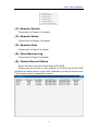
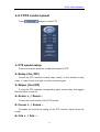
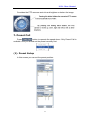
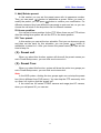
NVR Client Manual
NVR Client System
User’s Guide
I
NVR Client Manual
Content
Chapter1 Start up and Main interface............................ 9
1.1 Preparation & Uninstallation........................................................ 9
1.1.1 Preparation ....................................................................................... 9
1.1.2 Uninstallation...................................................................................11
1.1.3 Search Tools .....................................................................................11
1.2 Start up........................................................................................ 13
1.3 Main interface............................................................................. 14
1.3.1 Show tips ......................................................................................... 14
1.3.2 Screen menu .................................................................................... 14
1.3.3 Interface description ....................................................................... 16
1.3.4 System Menu ................................................................................... 18
1.3.5 Connection group............................................................................ 21
1.3.6 Connection list ................................................................................ 21
1.3.7 PTZ control panel ........................................................................... 24
1.3.8 Color/Audio adjustment .................................................................. 27
1.3.9 DI/DO Control ................................................................................ 28
Chapter2 Local setup.................................................... 30
2.1 System setup............................................................................... 30
2.1.1 System setup .................................................................................... 30
2.1.2 Add/Modify server........................................................................... 35
II
NVR Client Manual
2.2 Group setup ................................................................................ 36
2.3 Record setup ............................................................................... 38
2.4 Right setup.................................................................................. 40
2.4.1 User setup ....................................................................................... 40
2.4.2 Right setup....................................................................................... 41
Chapter3 Local search.................................................. 42
3.1 Main interface............................................................................. 42
3.2 Partition mode ............................................................................ 42
3.3 Playback ..................................................................................... 43
3.3.1 Select date ....................................................................................... 43
3.3.2 Select Record type ........................................................................... 43
3.3.3 Select camera .................................................................................. 44
3.3.4 Select file ......................................................................................... 44
3.4 Play file and related operations .................................................. 45
3.4.1 Play files.......................................................................................... 45
3.4.2 Capture pictures .............................................................................. 46
3.4.3 Search captured pictures................................................................. 46
3.5 Backup........................................................................................ 48
3.5.1 Create file clip................................................................................. 48
3.5.2 Backup by Time ............................................................................... 49
3.5.3 View backup file .............................................................................. 51
III
NVR Client Manual
3.5.4 Burn CD .......................................................................................... 51
Chapter4 Remote setup ................................................ 53
4.1 For PC-DVR............................................................................... 53
4.2 For DVS and EM-DVR.............................................................. 53
4.2.1 Functional buttons .......................................................................... 54
4.2.2 Server setup..................................................................................... 55
4.2.3 Channel setup.................................................................................. 56
4.2.4 PTZ control ..................................................................................... 58
4.2.5 Sensor setup .................................................................................... 61
4.2.6 Alarm setup ..................................................................................... 63
Chapter5 Remote Search ............................................. 65
5.1 Steps of Playback .......................................错误!未定义书签。
5.2 Play File and Related Operations...............错误!未定义书签。
5.3 Backup........................................................错误!未定义书签。
5.3.1 Create File Clip............................................... 错误!未定义书签。
5.3.2 Backup Record by Time................................... 错误!未定义书签。
5.3.3 View Backup Video File................................... 错误!未定义书签。
5.3.4 Burn Video File to DVD/CD ........................... 错误!未定义书签。
Chapter6 IE client .......................................................... 65
6.1 Functions of IE Client ................................................................ 71
6.2 Main Interface ............................................................................ 71
IV
NVR Client Manual
6.2.1 Connect Record............................................................................... 72
6.2.2 Partition Mode ................................................................................ 72
6.2.3 PTZ Control..................................................................................... 73
6.2.4 Local & Remote Search .................................................................. 73
6.2.5 Quit Program .................................................................................. 73
6.3 Local Search ............................................................................... 73
6.4 Remote Search............................................................................ 75
Chapter7 Appendix A: E-Map function........................ 77
7.1 Introduction ................................................................................ 77
7.1.1 E-Map Introduction......................................................................... 77
7.1.2 Corresponding configuration of E-Map ......................................... 77
7.1.3 Single Monitor................................................................................. 77
7.1.4 Dual Monitor................................................................................... 80
7.2 Main interface............................................................................. 85
7.3 E-Map Menu............................................................................... 86
7.3.1 Map setup........................................................................................ 86
7.4 Connect server while alarm........................................................ 90
V
NVR Client Manual
Introductions
Thank you for purchasing our NVR client system. This NVR client system
can connect PC-DVR (NV DVR system), EM-DVR and DVS. Also, it can set
them and search their recording data remotely. In addition, it can view server’s
log (only for PC-DVR) from long-distance,supporting IE browser connect DVR
client.
New Functions
1. Onvif supported. Refer to Page 35.
2. Search multi-server at a time remotely. Refer to Page 65.
3. MAC OS supported. User can ask our sales to offer this version.
4. View up to 4 channels via iPhone mobileclient.
5. Ipad supported.
6. Webclient updated. Refer to Page 68.
For point 4 & 5, please refer to our iPhone user manual for details.
System Features
-Support mobile client, such as Andriod, iPhone and Blackberry etc.
-Support the following eight kinds of resolution: 1024*768 pixels,
1280*768 pixels, 1280*1024 pixels, 1366*768 pixels, 1440*900 pixels,
1600*900 pixels, 1680*1050 pixels and 1920*1080 pixels.
-Support 64bit OS installation.
-Support PC Decoder function. It is integrated to support multi-monitor for
TV wall function. User can drag any board card cameras or IP cameras
supported by our software to any window on TV wall. You can connect as
many as 24 monitors to the system.
-Support E-Map function. It can be used to deal with variety alarms, such
as sensor alarm, motion detection alarm etc. It can switch to display video
images of related alarm cameras automatically. User can click them to locate
where the alarm be triggered out. And the corresponding names of camera will
be displayed on screen.
-Support remote motion setup for PC-DVR
-Support multi-brand of IP cameras, such as Mobotix, Sony, Acti,
Arecontvision, Vivotek and SanYo etc.
-Support playing back according to device name
-Support instant playback in 480 sec
7
NVR Client Manual
-Support write log while alarm. User can search the record video in system
log
-Support display the video from alarm server automatically
-Support adjust the window split mode between Normal mode and Wide
screen mode
-P/T/Z/F & speed demo control on keyboard
-Network support (Remote access via LAN, Ethernet, PSTN, ISDN, ADSL)
Important Information
For optimal performance of your system, it is important to follow these
recommendations.
We recommend that you divide your hard disk into two partitions (E.g. C
and D) at least. The first partition is used to install Windows OS and system
software, the other for storing record files. Each partition should not be larger
than 2.5TB.
Please use appropriate motherboard and display card. Contact your
dealers or our support engineers if you have questions.
Recommended System Requirements
Chipset: Intel 875PE, 915P, 945P, 965P
Motherboard: Intel: D915/945PCY, D865PERL
Asus: P4P800SE, P5P800 MSI: 865PE Neo2-F, 915/925/945;
Gigabit: GA-865GME, GA-945PL-G etc
Video Card: ATI Rodeon 9250 128MB, ATI Radeon 9550 128MB, ATI
X500, X550, X700 etc;
Processor: Intel Pentium 4 2.4GHz or better
Memory: 512MB minimum
8
NVR Client Manual
Chapter1 Start up and Main
interface
1.1 Preparation & Uninstallation
When you want to mix your MT cards and EW cards on the same PC, you
have to use DVR 6.38. So you have to update NVR to 6.38 to avoid there are
problems when do remote setup from NVR client.
1.1.1 Preparation
After installing NVR Client, user must assign space for recording.
Otherwise, software can’t record normally. Actually, system will run the disk
management automatically before user runs NVR Client the first time. Also,
user can run disk manager to assign space when you want.
However, you should input correct user name and password to get access
to Disk management when manger disables the disk manage right of some
operators in Right setup.
For details, please refer to the particular manual in DVR server manual.
In order to make NVR client run normally in windows 7 OS, please take
note one of the following things must be done:
9
NVR Client Manual
1. Activate "administrator" to do all the operations, such as install
software, operate software, etc. The steps to activate are as below:
First, single-right-click “Computer” icon->Manage->Local Users and
Groups->Users->Administrators->not to check “Account is disabled”.
Then, switch user or log off to log in with Administrator.
2. Adjust UAC settings to "Never notify", shown in the below pictures:
10
NVR Client Manual
To 64 bit OS, you have to download and install two patches: KB978637
and KB976264. You should download them from MSDNAA manually. They
can’t be installed automatically when system updates.
1.1.2 Uninstallation
When you want to change this version to another one, you should uninstall
it. Click Startà All programsà NVR Clientà Uninstall NVR Client to uninstall
NVR.
1.1.3 Search Tools
1. NV Series IPC Scan
Click Startà All programsà NVR_Clientà Insatll WinPcap_4_0_2 to
install the NV series IPC scan tool.
11
NVR Client Manual
Click Startà All programsà NVR_Clientà NV Series IPC Scan to scan
NV series IP cameras connected in the LAN.
Device type, IP address, Port number, Device Serial No., mask, mac,
channels, software version, DSP version and start time will be displayed in the
search tool. You can modify the IP and port more conveniently when you click
“modify” button on the right.
2. DG Series IPC Scan
Click Startà All programsà NVR_Clientà DG Series IPC Scan to scan
12
NVR Client Manual
DG series IP cameras connected in the LAN.
IP Address, MAC Address, Mask, Gateway, Server Type, Channel Num,
Server Port, Client Port and Domain will be displayed in the search tool. You
can modify the IP and port more conveniently when you double click one
camera in the list.
1.2 Start up
After installing NVR Client software, a shortcut icon
will be
shown on windows desktop. Double click it to run NVR Client software, the
main interface will appear as the follows:
13
NVR Client Manual
1.3 Main interface
1.3.1 Show tips
1. When the mouse moves closely or stops above a button, a text tip will
be shown to interpret its function immediately;
2. Zoom in/out video image: Left-Double-Click a camera window to zoom
in/out video image;
3. Recording status:
--The system is recording continuously;
-- The system is recording manually;
-- The system is recording in motion detection alarm;
-- The system is recording in event alarm.
1.3.2 Screen menu
Normally, user can press TAB key or Page Down (select next camera
14
NVR Client Manual
window) and Page UP (select previous camera window) key on keyboard to
select a window.
Users can Single-Right-Click image area (PC-DVR camera windows and
IP camera windows) to popup the screen menu as below:
1. Full screen display: single-right-click to change the display mode to
full screen mode, click again to turn back.
2. Instant playback: if you have set “Instant playback max time” in the
local setup, then you can use this shortcut function.
Note:
In the course of instant playback(for both of the compression card camera
and the IP camera), you can press Space key to switch the play/pause status
and direction key → or ← to play next or previous frame.
3. End playback: to end playback.
4. Image quality, Frame rate, Resolution: for the sub-stream of PCDVR,
you can adjust the Image quality, Frame rate and Resolution. This
function is only available to PC-DVR that enabled sub stream in
camera setup.
5. IP Video zoom in: zoom in IP video.
6. Switch to sub stream: can be the main / sub-channel switching, if you
choose the sub-channel, the images will be poorer.
7. PC DVR Motion setup: Enter the motion setup remotely. It’s only
available for PC-DVR. For details, you can refer to the DVR user
manual.
8. Views Manual/Auto Adjust: if you choose Views Auto Adjust when
15
NVR Client Manual
there is an alarm in E-map, software will adjust it’s splits automatically
to display the cameras with alarm. Otherwise, it will not change its
splits even the alarm cameras are more than the windows.
9. Device abnormity message: When the server is abnormally shut down
and restart, there will be a massage record. To know the details, you
can view the remote log.
10. About IP register: Click this function, the registered and unregistered
device information will be displayed.
11. PC Decoder Function: Please refer to PC Decoder Manual for details.
Note:
Show prompt: When the mouse moves closely or stops over a button, the
button function text prompt will be shown immediately.
1.3.3 Interface description
1. Partition mode
Press
button to set display mode. There are many types of the
partition, including 1,4,6,9,13,16,20,25,28,33,36,40,49,64 partition. Select the
suitable partition according to your need.
2. Image capture
Press
button to save a still image of a selected camera in live view
that is selected by user onto hard disk, and then review and print the image.
3. Manual record switch
Press
button to record manually to any camera, after manual
recording, must stop manually.
4. Information panel
Date, time and display window information panel Information: Show day of
16
NVR Client Manual
the week, current date, current time, and the percentage of CPU usage, the
current selected window, and the current linkage in this window.
5. System lock
After you enabled “use password” in Right setup, press
button to
lock system-Lock keyboard and mouse to prevent unauthorized user to
operate NVR Client system. Left-Single-Click this button to acquire the
operation rights by entering the user and password, default user ID is “admin”,
no password.
6. Setting
button to enter Local setup submenu. In this menu, you
Press
can set system and related parameters.
7. Playback
Click
button in main interface to enter Remote playback
interface.
8. Minimize button
Press
button to minimize the main window.
9. Exit program
Press
button to exit program.
After clicking this button, a dialog will be displayed. Click “OK” to quit NVR
system.
17
NVR Client Manual
1.3.4 System Menu
1. Device Record Status
Select this item to view the record status of PC-DVR.
Please note this function is only available to PC-DVR and the PC-DVR
should be the same version of your NVR. Otherwise, you will get an error says
“The IP device doesn’t support this function”.
18
NVR Client Manual
2. Remote Chat
Press Remote Chat to make a voice chatting. Click it to have remote chat
with the connected server. Sound card with mice input must be used. If there is
no sound card on either side, the chat will not be carried on.
Select a server from drop-down list to make a remote chat. If connect
successfully, there will be an icon tip to show it.
.
3. View Remote log
19
NVR Client Manual
Press
button to search log from a long distance server that you are
being connected. It’s good that no one is on duty in server end. You can see
information of the server and you needn’t get to the server site.
Note:
Remote log is only available to PC-DVR.
4. View Local log
Local system log keeps a record of system events such as local operation,
local prompt, local system alarm and DVR device alarm according to time and
date. Users can search log by date, time and system parameters.
When there is a motion alarm triggered out, user can view its record on
the right top of this interface. But you should confirm you have enabled “write
log while alarm” in local system setup first. Besides, if the motion alarm lasts
only for a short time, there may be no picture record in system log.
5. Local Playback
20
NVR Client Manual
Select Local Playback to enter Local Playback submenu.
6. Remote setup
Select Remote Setup to enter Remote setup submenu. In this menu, you
can set the server’s parameters remotely.
7. Backup System parameters
Backup the system parameters to the select path.
8. Import System parameters
Import system parameters form the save path.
1.3.5 Connection group
Press
to enter connection group setup. This panel
displays the information of groups and cameras.
There are 18 preset groups and you can choose any one group to connect.
There are 64 windows and you can also click
and click
to connect all of them
to disconnect all. The shade of icon will show the status of
window:
Window 1 disconnects
Window 2 connects
1.3.6 Connection list
1. List
Press
button to show all the equipments you have added
in this client.
21
NVR Client Manual
Double click one camera and it will be connected in a selected window.
2. Quick Operations
There will be a menu shown as below if you Single-Right-Click on the
sever name.
22
NVR Client Manual
(1). Remote Search
Please refer to Chapter 5 for details.
(2). Remote Setup
Please refer to Chapter 4 for details.
(3). Remote Chat
Please refer to Page 11 for details.
(4). View Remote Log
Please refer to Page 16 for details
(5). Device Record Status
Select this item to view the record status of PC-DVR.
Please note this function is only available to PC-DVR and the PC-DVR
should be the same version of your NVR. Otherwise, you will get an error says
“The IP device doesn’t support this function”.
23
NVR Client Manual
1.3.7 PTZ control panel
Press
button to control PTZ.
1. PTZ speed setup
Press and drag the slider bar to adjust the speed of PTZ.
2. Relay (On/Off)
Control the PTZ cameras internal relay (relay1) or the decoder’s relay
(relay 1). Used to turn on a light or control an access gate.
3. Wiper (On/Off)
If using the PTZ cameras corresponding wiper control relay, this toggles
the relay/wiper on and off.
4. Zoom + / Zoom –
Control the zoom function of the PTZ camera.
5. Focus + / Focus –
Overrides the auto-focus setting of the PTZ camera, adjust focus the
image.
6. Iris + / Iris –
24
NVR Client Manual
Overrides the PTZ cameras auto-iris and brighten or darken the image.
7. Preset Call
Press
button to operate the speed dome. Only Preset Call is
available. And you should set the preset remotely first.
(1). Preset Setup
In this screen you can set the preset position:
25
NVR Client Manual
I. Add/Delete preset
In this section you can set the preset name with its sequence number.
/ button to add/delete a preset. When you want to
Then you can press
modify the preset, you can press
button to confirm your modification. For
different cameras, they have different commands to open and set, so you can
choose the call mode in the drop-down list for different cameras.
II. Home position
You can set a home position for the PTZ. When there are no PTZ actions
after the setting time system will call the PTZ to the home position.
III. Tour preset
In this section you can set the tour schedule. First you can choose a group,
/
button to
and then set the track for this schedule; you can press
add/delete a preset to it. After you choose the preset name you can set the
time to keep on.
(2). Preset call
When you select this function, system will show all the preset names you
set in Preset Setup menu; you can click one to move to it.
(3). Preset Tour
When you select this function, system will show the entire tour groups you
set in Preset Setup menu; you can click one to execute it.
Note:
In the NVR system, clicking the tour groups again can not stop the preset
tour (this is different from DVR server). You can stop the PTZ camera by click
up, down, left, right or click the “preset call”.
If the views are NV series PTZ&IP camera and mega pixel IP camera,
when you call preset 95, you can see:
26
NVR Client Manual
When you enter the menu, you can control it by
IRIS – (
down, left and right buttons. Press
, using up,
) to enter the
sub menu. When you use up or down to move to “exit”, press IRIS- to exit the
menu.
For details, please refer to Chapter 4 in Network_Camera_Menu for
details.
8. Control PTZ via video window
Press and drag the mouse to the corresponding area to control the PTZ
when there is a decoder.
1.3.8 Color/Audio adjustment
Press
button to enter Color/Audio Adjust Panel-Slider
adjustments for the video image and recording volume of the selected tile. This
also affects the live view of the video images.
27
NVR Client Manual
① Press the first button and drag to adjust the brightness of the image
that you selected, and you can resume its default value by pressing .
②Press the second button and drag it to adjust the contrast of the image
that you selected and you can resume its default value by pressing .
③Press the third button and drag it to adjust the hue of the image that you
selected, and you can resume its default value by pressing
.
④Press the fourth button and drag it to adjust the saturation of the image
that you selected, and you can resume its default value by pressing .
⑤Press the fifth button to switch sound of the audio that related to the
image you selected and drag the slider bar to adjust the volume.
1.3.9 DI/DO Control
28
NVR Client Manual
Note:
The channel of DI and DO is determined by the connected server.
1. DI control
The DI number will show the alarm status of the corresponding server
indicated by the shades of the icon:
Input channel 2 doesn’t check sensor forcibly.
Input channel 3 checks sensor forcibly or has an alarm inputting.
When there is no alarm yet, user can press number button to check
sensor forcibly. Press the button again to stop checking all time, then system
checks sensor according to Sensor setup. When there is an alarm, the
corresponding button will show the alarm with blue.
2. DO control
Press number to open/close alarm device relay switch manually. There
are two types of status to DO:
Output channel 2 is close.
Output channel 3 is open.
When there is no alarm triggered out, user can press the number button to
output alarm forcibly and the button will show it with green, press it again the
output will be closed.
29
NVR Client Manual
Chapter2 Local setup
2.1 System setup
Click
button to enter this interface:
【Import】
Select this function to export system configurations.
【Export】
Select this function to import system configurations.
2.1.1 System setup
【Max. Record channels】Set the max record channels, the max number
is 64, if set the number as 20(shown as below):
30
NVR Client Manual
Then you can set the windows1-windowns20 in Record Set.
【Display Resolution】Select the display resolution for NVR. You can
choose from "Auto, 1024*768, 1280*768, 1280*1024, 1366*768, 1440*900,
1600*900, 1680*1050 and 1920*1080". When you select "auto", the software
will adjust its resolution in accordance with the resolution of the screen
automatically.
【Network Listen port】The alarm port to connect the client. Set in server.
31
NVR Client Manual
Restart NVR Client software to make it efficiently.
【Web Listen port】The IE client connect port. Restart NVR Client
software to make it efficiently.
【Use electronic map】Select be disable or enable to use the electronic
map. At the same time, you should choose the mode from stretched and
extended. Please refer to E-map manual for details.
【Connect server while alarm】Enable: If there is an alarm in DVR
server end, the client will connect the DVR server forwardly.
【Data stream Auto adjust】1,1-4,1-6,1-9,1-13,1-16View->Main Stream,
when you select one, all the view less than you select should be main stream.
【Write log while alarm】Select whether system writes alarm information
log or not. There will be alarm information and corresponding record in local
system log when you select enable.
【Default Connect Stream Type】Select the stream type as default.
【Auto Reconnect Time Interval】If you select the “Auto Reconnect Time
Interval” function, when the software is disconnected, the software will
reconnect auto by the setting time.
【Instant playback max time】Set the instant playback max time or
disable the function. If you select “180sec” then you can use “Instant playback”
in the main interface as bellow:
【Matrix card work mode】If use matrix and decode card, select work
mode from D1 decode mode or CIF decode mode and set it.
Note:
Each EW4002MD card can decode 2 channels D1 or 4channels CIF.
32
NVR Client Manual
Each EW4004MD card can decode 4 channels D1 or 8 channels CIF.
Decoder will send out corresponding number channels from the first
window in sequence.
User can set each output port individually.
【TV output port】Select decoder card output port.
【TV output View Mode】Set the split mode for selected port.
【Window index of TV port】Select the index for each split window.
For example:
This icon has four windows: window1, window2, window3,
window4.
【Decode channel Index in window】
Select window index for the selected window. Each window can only
select one decode channel. The number of decode channel will be showed
automatically according to the channels of the decode card. For example, if
there is one EW4004MD card, there will show the 8 decode channel, if there
are two EW4004MD cards, there will show the 16 decode channel, if one
4002MD card, there are 4 decode channel only.
33
NVR Client Manual
This figure as above shows the decode channel have been selected, in
order that user can’t select the decoder repeatedly.
Note:
If use “CIF decode mode”, and there isn’t preview video appear in the
NVR client main interface. The reason for this is that the resolution setup too
high in DVR Server end. For example: D1. (Please restart NVR Client software
after this item setup).
【Software Start Auto Connect】Select the group set in Group setup to
be connected when the program start. When you select “Disable”, Client will
not connect the camera automatically.
【Auto Reconnect time interval】Select whether the client reconnect
when the connection is interrupted and the time interval. If you select “Disable”,
when the connection is interrupted, program will not reconnect it.
If you select the “Auto Reconnect Time Interval” function, when the
software is disconnected, the software will reconnect automatically after the
setting time.
【Keyboard use COM port】Select a COM port for keyboard to connect.
Please refer to Keyboard Manual for details.
【Grab picture save to】Fill in the save path that you want your captured
pictures to be saved to.
【Language】Show the current language. You can change when there is
another language pack.
【Window Split Mode】Select window split mode for NVR between
“Normal Mode” and “Wide Screen”. You would better select “Wide Screen”
when you are using wide screen monitor. You should re-select the view
window number to refresh the window split mode status.
【PC Decoder Function】Select “Enable” so that you can use PC
decoder funtion later. It will be described in details in Chapter 8.
【PDA Connect Port】The port is for PDA connection. Blackberry and
iPhone etc are supported. When connect a mobile client to NVR, all severs
connected in NVR will listed in your mobile. Select one from the list to view or
operate.
34
NVR Client Manual
Please refer to DVR User Manual for details about mobile client.
2.1.2 Add/Modify server
【Add connect server】Press
button to add a new server in
this system. When user is adding a new server, if there are some problems,
e.g.: network is poor or this Server is not running, the adding will be failed.
【Server Name】Input a name that is easy to identify.
【Device Type】Select device type you will add. This client system can
connect PC-DVR (NV DVR Server system), DVS and EM-DVR. Now the
system supports the following types of device: PC DVR, NV Series IP/EMDVR,
DG 42XX/50XX EMDVR, DG 80XX/90XX EMDVR, DG Series IPC, Dahua
Series IP, Sony SNC110/160, ACTi Series IP, Huviron Series IP, Mobotix M12
Series IP, ArecontVision IP, Camtron Series IPC, Axis Series IPC, Vivotek
Series IPC and SanYo Series IPC.
Note:
All cameras support onvif can also be supported by our software. You can
add them to our software as normal IP cameras. The only difference is you
have to select ONVIF IPC as the device name.
35
NVR Client Manual
【IP Address】Set IP address of server host.
【Connect Port】Set the port through which connects to DVR Server.
【Login user ID/Login Pass】When the client want to visit server and the
server has used the function of rights management, login user ID and
password will be checked. If the user has no right to visit that camera, connect
will be cut down automatically. If the function is not used, the id and password
will not be checked.
【If use DNS to get IP】Select whether use DNS to get IP or not, if the
server end is the dynamic IP address, users need use DNS to get the server’s
IP.
【DNS Server IP】Set IP address of DNS server host.
【DNS Server Port】DNS server host’s port, which is provide to connect
DNS software.
【Modify server】Press
button to modify server information, its
interface is same as Add Connected Server.
【 Delete connected server 】 Press
button to delete a
connected server.
【Motion Alarm Play Wave File】Select the wave file which the motion
alarm plays.
【Sensor Alarm Play Wave File】Select the wave file which the sensor
alarm plays.
Note:
When you finish the setups you should save your changes by pressing
SAVE button before you exit setup.
2.2 Group setup
Click
button to enter the following window:
36
NVR Client Manual
Choose a group from drop-down list behind “Select Setup Group” first.
There are 32 groups.
There are now 2 ways to set the display group as below:
Add a Server and arrange the display windows automatically:
With this function, clients can select a server in “Select Device Name” on
the top of the interface, click “Add” button, software will switch the partition
mode, and arrange each camera into the window according to the order of the
cameras.
Arrange the display windows / cameras manually:
In every group, you can set 64 connections. Also, you can select the
partition for every group from the drop-down list behind “Partition Mode”. Then
you can set group as follows:
【IP Address Alias】Select the server in which the camera will be selected
to show If it has no sever in the drop-down list, you need to add server in the
“Server IP” page.
【Camera】Select the camera of the server set in 【IP Address Alias】 to
be connected. In one window, you can set one or more camera’s connection (),
if more than one camera show in one window, you can set cycle interval time.
You can switch them by pressing button
interface.
37
and
in Main
NVR Client Manual
【Frame Rate】There are three options: Real-time, Auto and 1fps.
Real-time: If it’s selected, server will send all compacted information to
client. When the client gets this information, it will play it. The continuality is
good in this way but it consumes too much CPU space. If there is no
information losing when compacting and sending, the playing will be real-time.
Auto: Its difference from Real-time is that when the client gets the
information, he will cut some information and then play it. It consumes less
CPU space. But if you click any camera, system will adjust frame rate to
Real-time automatically.
1fps: It means to break down the information in server. Only one frame of
important information is sent to the client every second. It consumes little CPU
space and network. And if you click any camera, system will adjust frame rate
to Real-time automatically when there is enough network space. (NOTE: This
selection is only effective on PC-DVR).
【Stream Type】Select the stream type main channel or sub channel for
the current camera.
2.3 Record setup
Click
to enter the record setup interface.
38
NVR Client Manual
【Select Window】Select the window you want to set.
【Record type】Set the type of record, including Normal record, Sensor
record, Motion record, Motion or Sensor record and Not record. You can
set record type as follows:
Firstly, press the type button that you want to set; then select the record
time by press the grid (delegate half an hour in a day) or left-click mouse and
drag for an area. If you want to set same record status every half hour every
day, you may double-click the left up of the chart.
When you finished the setup, the grid will display the corresponding color
of the record type.
Green: Normal Record.
Red: Sensor Record.
Blue: Motion Record.
Yellow: Motion or Sensor Record.
Gray: Not Record.
【Copy Record Plan to】Copy the setup to any other window or all
windows.
39
NVR Client Manual
2.4 Right setup
Click
button to set user right.
2.4.1 User setup
【Add User/Del User】Click
/
icons to add /delete user
for the Client, after that you can edit the information for the user to be added.
【Select User ID】Select a user that has existed in the system to be
modified from drop-down list.
【Use Password management】Select a solution to determine if enable
user password validation. When you select enable, when user login, password
is needed.
【User ID】Input new User ID in this box when add a new user to system.
【Select User ID】This selection is unavailable.
【Password】Set new user and selected user’s password.
【Auth. Level】Select user type. When you select admin in【Select User
ID】this selection is unavailable.
【Confirm password】Confirm password again.
40
NVR Client Manual
2.4.2 Right setup
You can set user management in this window after you input user name
and password and you will have corresponding rights with your name. Choose
a user and distribute corresponding right.
When manager doesn’t want some operators to manage disk, he should
not check this right for those users. For example, “admin” doesn’t want “user”
to own the right, he should select “user” first, and click “Modify”, and then,
check the “V” in front of “Disk Management”.
to save the information.
After set, click the button
41
NVR Client Manual
Chapter3 Local search
3.1 Main interface
Select Local Playback to enter local search interface as below:
3.2 Partition mode
Press
button to select partition mode, there are1, 4, 9 and 16
partitions mode. In the server end user can only connect 16 channels
simultaneously. When the connected channels exceed the limit, system will
popup information to indicate it.
42
NVR Client Manual
3.3 Playback
3.3.1 Select date
Select one window (the 1st one in default), and then click
button to
show the date.
The blue dates contain recorded data. The green date is the current date.
The gray dates signify no data. Only those blue ones can be selected and
when they are selected the camera window will appear automatically to show
which cameras has record data.
Click
or
to change month and year of search data.
3.3.2 Select Record type
Press the icon
before “Motion” when you want to playback motion
recording. Others are the same.
43
NVR Client Manual
When there is no record data of the selected record type, the below
picture will be shown.
3.3.3 Select camera
After selected the date system will show the camera state of
corresponding day, or click
button directly to show the cameras state of
current day. The number button with navy blue means this channel has record
data. By pressing it directly on the numerical panel, DVR system will play back
recorded data from the first file.
3.3.4 Select file
After selecting the camera to play user can click
button to show all
the files of this camera.
By default, system will play back video file from the first one. In this screen
you can change the file you want to play by clicking it directly.
The camera list below the window shows the recorded data of the day you
select. Double click any time with record data, a red mark will be there. Then
use
to enlarge the time bar, so that you can select an exact time you
want to playback.
When there are too much record data, you can use
select.
Press
or
to view the record data of other cameras.
44
to
NVR Client Manual
The red bar shows the exact time when system is playing back now.
Note:
When you check Filter by Server in Date Select panel, there will be a
server list in Camera Select panel. Select one server to search its record data.
Also, user can click
button to show all the files of this camera.
3.4 Play file and related operations
3.4.1 Play files
Press
button to open all playback windows in turns according to
the order of the cameras.
Note:
If you press this button as soon as you enter the playback interface, all the
cameras will be played back from the beginning of this day when there is
record data. For example, there is record data from 8:00 AM to all cameras,
then, they will be played back from 8:00 AM. If you select a point of time on the
time bar and then press this button, then, all the cameras will be played back
from that time.
Press
button to close all playback windows.
45
NVR Client Manual
Click this button to synchronize all playback
channels time.
Last frame, Start, Pause, Stop and Next frame.
First frame of that day, Previous minute, Next minute
and Last frame of that day.
Image zooms out: Press this button, single click the left mouse button
on an image, quarter of the image will be enlarge. By thereafter, single click
right mouse button on the image, it will resume.
Adjust the voice: click the button to clear the
voice.
Adjust playing speed: click the button to resume
normal playing speed.
Note:
It is not suggested that multi-channel (more than 10 channels) record and
playback coinstantaneous unless your PC has a wonderful configuration,
because the data throughput of HDD is huge. Multi-channel search in client
and server are the same except their paths. In client, there are local and LAN
search. In LAN search, it searches among the record data in the local network
of server.
3.4.2 Capture pictures
Click capture button
to capture a display picture. When one is
captured, there will display a dialog interface and you can change the file name.
After you press confirmation, system will save the picture in default path:
System volume\Grab\search.
Note:
The size of the image is that of the playing window.
3.4.3 Search captured pictures
Click
to enter the search window.
46
NVR Client Manual
1. Select pictures from directory and file list
You can select a captured picture from directory list and file list in local
disk. By default, the directory is: System volume\Grab\Search. After you select
the path the file name will show in the top of the window.
2. Related operations
After you edit the picture you can save the picture in a save path
as you like.
Function buttons of picture
disposal.
When the result of disposal is not good click it to the default.
47
NVR Client Manual
Print picture, when the image is wider than 400 pixels, it will be
printed smaller. On the other hand, it will be printed bigger.
When it’s bright, with the mouse moving, part of the picture will be
enlarged.
Delete current file or delete all files.
3.5 Backup
Click button
,there are follow 4 items to select.
3.5.1 Create file clip
Click Create file clip to create file clip.
48
NVR Client Manual
1. Select channel and path
Select channel and path of the backup file on the top of interface.
2. File list and attribute
Select a file and double-click it to play and its attribute will display below
the list, including begin time, end time, file size, resolution, frame rate etc.
3. Play file and related operations
(1). Play control
Press and drag slider on
button to control the player time.
(2). Beginning and stop time setup
Press
to set the beginning time and end time of the file,
the file attribute on the left will show the size of the file.
(3). Save file
Press
the file.
to ensure the beginning and end of the file, click it to save
(4). Voice control
Click
to control voice, press it to clear voice.
3.5.2 Backup by Time
Click Backup by time to backup by time.
49
NVR Client Manual
1. Save Path
Select path for the backup file, User can backup record file to CD.
2. Backup Camera
Select the backup camera. User can select more than one camera once.
3. Select begin/end time
Select the backup files’ begin time and end time.
4. Backup Data Size
Show the size of the backup file. If user backups record file to CD directly,
the data size should not be more than 650M.
Note:
If user backup record files to CD directly, the system disk volume’s(C
volume in general) free space should not less than twice of the backup data
size. Because system volume will be used buffer area when burn CD. For
example, if the backup data size is 450M, so, the system volume’s free space
50
NVR Client Manual
should be more than 900M.
The process of burning CD:
1) Select CD-ROM as the backup path, and select the camera
and time;
2) Check the backup file value;
3) Backup the file to the temporary file in the last volume if there
have enough free space, otherwise, write backup file to the last
second volume;
4) Write back up file to buffer;
5) Write CD;
6) Delete buffer and temporary file.
3.5.3 View backup file
to view backup files.
Press
Select channel and path of the backup file in local disk on the top of
interface.
3.5.4 Burn CD
Press
button to burn CD.
51
NVR Client Manual
①
④
②
③
Area ①: File directory.
Area ②: File list.
Area ③: The File directory and list of will be burned to CD.
Icon ④: Create a new directory in area ③.
: Add selected file from area ② to area ③.
: Delete selected file from area ③.
【Burn CD drive】Select CD-ROM driver.
【Volume label】 Set the CD’s label.
【Total file size】Show the size of all files will be burned to CD.
: When you finish your setup, click this button will write file to CD.
52
NVR Client Manual
Chapter4 Remote setup
4.1 For PC-DVR
Remote setup for PC-DVR is nearly the same as local setup in DVR. For
details, please refer to our DVR User Manual.
4.2 For DVS and EM-DVR
The remote setup interface of NV Series IP devices is as below:
For DG Series EM-DVR, the interfaces are not exactly the same as NV
Series. Remote setup for DG Series EM-DVR includes Server, Channel,
Record, PTZ, Sensor, Alarm and User.
But the ways of set are nearly the same. For details, please refer to our
DG Series EM-DVR manual.
For other series IP cameras, such as DG Series IP, Sony SNC110/160,
ACTi Series IP, Huviron Series IP, Mobotix M12 Series IP, ArecontVision IP,
Camtron Series IPC, Axis Series IPC, Vivotek Series IPC and SanYo Series
53
NVR Client Manual
IPC, you will enter the IE interface automatically when you press “Remote
Setup”. You have to install ActiveX too.
4.2.1 Functional buttons
There are 5 buttons in each page. They are Upgrade, Restart, Time
54
NVR Client Manual
adjustment, Save and Exit.
The system can upgrade to the server remote. Click this
button, and select the right file.
Some setting will only come into effect after device reboots.
Adjust date and time of DVS or EMDVR. The new date and
time will accordant with NVR client computer.
After setup is finished, click this button to save the setup.
Exit setup.
Remote setup for DVS includes Server, Channel, PTZ, Sensor and Alarm.
4.2.2 Server setup
Press
button to set server parameters remotely:
In the server window, some blanks’ background are gray. Those
parameters are read from foreside server, you can’t modify them. Other blanks
whose background is white, you can set them remotely.
【Server Name】Enter the name description for easy identification. This
name delegates the foreside server. If use DNS to get IP, this name will be
used.
55
NVR Client Manual
【IP configuration and related】
【Server IP】
【Port】
These are network configurations. You can set
LAN or Internet IP according to your need.
【Subnet Mask】
【Net Gate】
【Net Cable Type】
【If use PPPOE】
【PPPOE Login Name】
【PPPOE Login Pass】
If system uses PPPOE to connect with web,
please select it and input the PPPOE login
ID and password.
【User Pass】Set the user password of DVS remotely, after that operation
you should change the Login Pass to corresponding value in Add / Modify
server. Otherwise, you can’t connect the DVS correctly.
【DNS Server IP】If use DNS, input the DNS host IP address.
【Remote manage】
【Remote manage IP】
【Remote manage port】
Set the IP address and port of host
server who will receive the message
upload from foreside server
4.2.3 Channel setup
Press
button to set channel parameters.
56
NVR Client Manual
This section contains the parameters to designate a name for every
camera connected, to enable or disable show LOGO and OSD, and to set
display type of OSD & LOGO as well as record resolution, record type, record
quality and frame rate, etc.
【Camera】Select the camera to be set from the drop- list.
【Camera Name】Enter a name description for easy identification.
【Frame Rate】Select the record rate of camera from drop-down list.
【Mainstream】【Sub Stream】Select Mainstream or Sub Stream for the
current cameras.
【Resolution】Set the resolution at which the video files will be recorded.
Choices are DCIF, CIF, QCIF, 2CIF and 4CIF. The higher the resolution is, the
more disk space needed.
【Stream Type】Select video and audio or only video record.
【Image】Set the quality of the image to be recorded. Select from worst,
worse, normal, good and best.
【Bit Rate Type】Select bit rate type from Variable Bit Rate (VBR) and
Fixed Bit Rate (FBR) record:
VBR range= Poorest, Poor, Medium, Good, Best.
FBR range = 45 Megabytes/Hour to 400 Megabytes/Hour.
【Max Bit Rate】Select the maximum bit rate for Variable Bit Rate (VBR)
record.
57
NVR Client Manual
【Show LOGO/ OSD/ Week】If you check those box, system will show
corresponding information on screen.
【Position】Set the position of OSD or Logo by entering the X and Y
coordinate directly.
【OSD】Set the display attribute of the OSD & LOGO. There are four
types display modes: Clarity-Glitter, Clarity-Not Glitter, Not Clarity-Glitter and
Not Clarity-Not Glitter.
【OSD Type】Select the type of OSD for the Week.
【Privacy Mask】You can check this box to set the privacy mask on the
below image directly, and you can clear some privacy masks by pressing
button.
【Record schedule】You can set record schedule in following chart.
Note:
This record schedule is only available to EM-DVR. There are 4 time
segments every day. Every segment has start time, end time and record type.
The time segment is set in sequence; every segment can’t be overlapped,
included or skipped with any other.
【Copy to】After finishing one channel, if you want to set any other
channels’ configuration as the same as this camera, you can select channel
number
from
drop-down
list,
and
press
button.
, Set the time to post or pre
the record.
4.2.4 PTZ control
58
NVR Client Manual
Press
button to set PTZ.
In this screen, you can define the PTZ protocol and set the Preset Position
as well as the plan to execute them automatically.
【Camera】Select the camera to be set from the drop- list.
【Baud rate】Set baud rate according to PTZ protocol from the drop- list.
【PTZ Protocol】Select the communication protocol for the PTZ camera
from drop-down list.
【Copy to】After finishing one channel, if you want to set any other
channels’ configuration as the same as this camera, you can select channel
number from drop-down list, and press
button.
【PTZ Address】Set the address of the decoder, which must be matched
with the value of dipswitch in the PTZ.
【Speed】Set the speed of the PTZ.
【Preset position & schedule setup】Define preset position and set time
to call preset position automatically. System can add and delete plan time.
59
NVR Client Manual
【Name】 Set the name for the current preset. 【Preset】 Set the preset
Setup the preset by current
number for the current camera
configuration.
Delete the finished Preset.
Call the Preset if
the Mode is Call preset. The mode is save preset; you should save the preset
and shouldn’t call the preset.
Set disable or how long the
puts will come back to the home position when there is no PTZ action.
60
NVR Client Manual
【Preset】It can add the preset into the Preset Schedule, the preset set
completed in the Auto Pre yet, 【Call Time】
【Schedule List】Set the time of the
preset should be call at that time.
Tour Group
Add the Preset cameras into the Tour Group and set the Stay Time for
one tour group.
4.2.5 Sensor setup
Press
button to set sensor parameters.
61
NVR Client Manual
【Sensor NO】Select one sensor to be set.
【Sensor Name】Enter the name description of the sensor.
【Type】Select alarm type (sensor type) from “NO”(Normally Open) or
“NC”(Normally Close).
【Policy】Selecting “Sensor Alarm Handling” firstly, handling policies will
be available as follows:
On screen warning—Display the alarm information on the monitor.
Audio warning—Indicate the alarm with voice.
Upload to center—Update the alarm information to center.
Trigger alarm out—Trigger alarm box to output the alarm.
【Trigger record camera】Set cameras to record triggered by the alarm.
You can select one or more channels. When there is alarm input, the cameras
will be triggered to record (the record type of the channel is Alarm Record), and
the monitor will switch to preview the cameras (warning on monitor is enable).
【Preset】Set camera that will move to its one preset position when the
alarm happened.
【Schedule】Set alarm input precaution time firstly, then set time segment
according to the sequence. The time of each segment should not overlap the
others and no skips are allowed. After the precaution time of a certain day is
set, you can copy the parameter to other dates by select a day and press copy
button.
62
NVR Client Manual
【Copy to】After finishing one channel, if you want to set any other
channels’ configuration as the same as this camera, you can select channel
number from drop-down list, and press
button.
4.2.6 Alarm setup
Press
button to set alarm parameters.
【Camera】Select a camera to be set from the drop-down list and you can
copy the configuration to the other cameras by clicking copy button.
【Alarm Type】Select alarm type: Motion detection, Tempering alarm and
Video Loss.
【Level】Select sensibility levels from 0 (the lowest level) to 5 (the highest
63
NVR Client Manual
level) for the alarm.
【Set motion detection areas】Left-click mouse and drag it on the screen
to select motion detect area, you can select the whole area or many areas.
Also, you can clear one or whole area by press the button clear and test the
effect by clicking test button.
【Policy】Select “Handling current alarm” firstly, handling policies will be
available as follows:
On screen warning—Display the alarm information on the monitor.
Audio warning—Indicate the alarm with voice.
Upload to center—Update the alarm information to center.
Trigger alarm out—Trigger alarm box to output the alarm.
【Trigger record camera】Set cameras to record triggered by the alarm.
You can select one or more channels. When there is alarm input, the cameras
will be triggered to record (the record type of the channel is Alarm Record), and
the monitor will switch to preview the cameras (warning on monitor is enable).
【Schedule】Set alarm input precaution time. Select date firstly, then set
time segment according to the sequence. The time of each segment should
not overlap the others and no skips are allowed. After the precaution time of a
certain day is set, you can copy the parameter to other dates by select a day
and press copy button.
【Copy to】After finishing one channel, if you want to set any other
channels’ configuration as the same as this camera, you can select channel
number from drop-down list, and press
64
button.
NVR Client Manual
Chapter5 Remote Search
Click
button and then this window pop up. This is new feature of
our NVR V 6.60. It provides mutil-DVR playback and PC-DVR playback.
The mutil-DVR including recording data from EM-DVR, PC-DVR and DVS;
On the contrary, PC-DVR is listed seperately.
5.1 Mutil-Server playback
In the mutil-DVR playback interface, you will see as below:
65
NVR Client Manual
When entering this interface successfully, all devices (including
PC-DVR,EM-DVR,DVS with SD card) are not connected (by default). Showed
as below:
If you want to connect any device, just double-click the device, and it will
connect automatically. Similar for the other devices. More details about the
related operation please refer to from 5.3 to 5.5.
66
NVR Client Manual
5.2 PC-DVR playback
If you just want to playback video for a certain PC-DVR, click the button
and select the name of the PC-DVR, you will enter the interface as
below:
The related operation is the same with before. For more details, please
refer to contents from 5.3 to 5.5.
In this playback mode,we get several function those are popular among
customers back, such as PS, AS and CP.
The two modes of playback can fulfill different requirements of different
customers.
5.3 Steps of Playback
The operations are nearly the same with Local Playback. However, in
67
NVR Client Manual
multi-server playback mode you should double click the server name in the
server list to select one server before you select the date. Also, you can select
one camera below the server name to select the server. Otherwise, you will not
be able to select date.
And you can’t select record type as in Local Playback. The record type
icons below the time bar only show which record type you are playing back.
5.4 Play File and Related Operations
All buttons are nearly the same with Local Playback. However, you should
not press
button before one server is selected.
Please refer to Chapter 3 for details.
5.5 Backup
Click button
,there are four items to be selected.
5.5.1 Create File Clip
68
NVR Client Manual
Please refer to 3.5.1 for details. The only difference is you should select
one server from the drop-down list.
5.5.2 Backup Record by Time
It’s nearly the same with 4.5.2 in DVR User Manual. The differences are
as below:
69
NVR Client Manual
You should select one server before backup.
“No Change” is named as “MP4”.
“AVI (H.264)” and “MSMPG4” is named as “AVI”.
5.5.3 View Backup Video File
Please refer to 3.5.3 for details.
5.5.4 Burn Video File to DVD/CD
Please refer to 3.5.4 for details.
70
NVR Client Manual
Chapter6 IE client
The client user can look through video of DVR Client by Internet Explorer.
The default web server port is 80. If it is changed to other port, user should add
port number after IP address of NVR Client. E.g.: http://192.168.0.119:1290.
Note:
Webclient is updated from this version. If you can’t download and install
Activex automatically, you can download webclient.zip manually via clicking
“Go to”. Then, the following interface will be shown:
Save and install webclient on your PC, so that you can install ActiveX
sucessfully later.
6.1 Functions of IE Client
1. Video display and video storage.
2. Audio input.
3. Searching and playback video image locally or remotely.
4. Control PTZ and speed demo remotely.
6.2 Main Interface
When you connect DVR Client successfully, you should input valid User
ID and password in right up of the interface to acquire rights to play video and
other operations.
71
NVR Client Manual
6.2.1 Connect Record
This icon indicates the current connection and their record status:
Gray: Not connected.
Navy blue: Connected with no record.
Green: Connected with record.
You can change the record status by pressing corresponding number
button or change status of all connections at the same time by pressing
button.
6.2.2 Partition Mode
You can set the partition mode from the drop-down list file on the right up
of main interface. There are 1, 4,6,9,10,16 partition mode.
72
NVR Client Manual
6.2.3 PTZ Control
Most functions of PTZ control are same as Client in PTZ Control Panel.
6.2.4 Local & Remote Search
It will describe in Local Search and Remote Search in detail.
6.2.5 Quit Program
Press
button to shut down the IE Client.
6.3 Local Search
Press
button to enter local search.
73
NVR Client Manual
1. Display Setup and Data Information
In this area, you can select display partition mode, date, video channel
and its video file named according to time.
2. Playing Operation Area
In this area, you can operate video playing.
(1). Video-playing Time Adjustment
Press and drag slider bar to adjust video-playing time.
(2). Information Display Panel:
Display current window name,
camera name and record data information.
74
NVR Client Manual
(3). Playing Control Buttons
: Play, Pause, Stop
(4). Single Frame Play
: Previous frame, next frame
(5). Playing Speed Control
Slowly play
Fleetly play
6.4 Remote Search
Most functions and operations of Remote search are same as Local
Search; the different feature is that remote search added download feature.
When you playback, you click down
75
, system will save video of
NVR Client Manual
current channel you selected, and after save finish one file, it will popup prompt
to indicate its working.
Select one camera that has record data, open file list panel, select one
button, the selected data package
record data package, and click
will download fast.
Note:
When user use IE client to visit DVR Client, If connect successfully, there
will appear four partition blue window. If connect unsuccessfully, the reasons
possibly are:
The Web server port has been used by other programs.
Your computer didn’t download the player plug normally. The reason may
be the jurisdiction of your computer is too high, or your computer has plug filter.
76
NVR Client Manual
Chapter7 Appendix A: E-Map
function
7.1 Introduction
7.1.1 E-Map Introduction
E-Map is installed in NVR to deal with variety alarms, such as sensor
alarm, motion detection alarm etc. If the setup is ok, when alarm happens, it
will automatically switch to display video images of related alarm cameras
immediately. User can click them to locate where the alarm be triggered out.
And the corresponding names of camera will be displayed on screen.
7.1.2 Corresponding configuration of E-Map
Both of the single monitor and dual monitor support E-Map. There are
some referenced configurations and steps of setups for the above 2 situations.
7.1.3 Single Monitor
1. Configurations
NVR display resolution supports Auto, 1024*768, 1280*768, 1280*1024,
1440*900, 1680*1050 and 1920*1080. That is to say, 1024*768 is the least
display resolution for NVR. So, when there is only one monitor, user must set
its resolution more than 1024*768. Otherwise, user can’t use electro-map
function. When user opens NVR, the following dialog box will be displayed on
the screen if user has already enabled Use electronic map function in NVR
System Setup:
2. Steps of Setup
77
NVR Client Manual
(1). Set the resolution
↓
Note:
The screen resolution must be more than 1024*768 pixels if you want to
use E-Map.
(2). Add Server
User can add PC DVR and IP server into the system. If you don’t add any
78
NVR Client Manual
server in the system, you can’t add any device in the map. The Add/Modify
Server Information dialog box is showed as below:
(3). Set NVR display resolution
We suggest you set NVR Display Resolution as 1024*768, so that there
will be more space for electronic map.
79
NVR Client Manual
(4). Open electronic map function
Now, Connect Server While Alarm function is disabled automatically.
(5). Restart NVR
After the above operations, system will prompt you to restart NVR. The
setups will take effect after rebooting.
7.1.4 Dual Monitor
1. Configurations
(1). Stretch
The display card should support the dual monitor. We use ATI 9200
80
NVR Client Manual
display card. First you should connect the dual monitor to the display card.
The system can detect the dual monitors automatically, then you should
select “Stretch Desktop 1 horizontally onto monitor” and the interface as below
will be displayed:
81
NVR Client Manual
The desktop area should be selected about double size of the one monitor.
Now, the dual monitor is effective.
(2). Extend
Also, you can choose “Extend Main onto monitor”.
82
NVR Client Manual
The two monitors should be set as the same size. Otherwise, something
may be wrong. It’s shown as below.
83
NVR Client Manual
Note:
1). If the old ATI display card doesn't support the “CATALYST Control
Center”, you should download ATI Catalyst and install it ,then it can enter the
setting interface in ATI catalyst control center;
2). If the length or width exceeds the scope that the screen can display,
the monitor can’t display normally. In other words, when you are setting the
Desktop area, you should not only consider whether your display card
supports or not but also your screen;
3). If you select “Stretch Desktop 1 horizontally onto monitor”, you should
correspondingly choose “Stretched” in NVR system setup.
84
NVR Client Manual
4). If you select “Extend Main onto monitor”, you should choose
“Extended”.
2. Steps of Setup
Also,user should add server, set NVR display resolution, open electronic
map and restart NVR. The steps are the same as Steps of Setup for single
monitor except the set of resolution. You can set Display Resolution as any
one you like.
7.2 Main interface
85
NVR Client Manual
7.3 E-Map Menu
7.3.1 Map setup
Click Map Setup to do the following operations.
1. Add server and related operation
(1). Add device
86
NVR Client Manual
Select device with its type and sub map (press
button to select a
map with size from 160*120 to 640*480 pixels), and then press OK button to
finish adding a server. After that, the server icon will be displayed in the map
area on the right screen. At the same time, it will be displayed in the
compressed map.
Note:
When you press a server icon in the map, the sub map and name of it will
be displayed immediately. You can double-click sub map to close it;
You can only add the device that you have added in system setup. For
example, here is a list of the connected server:
When you have all servers added into the map, you can’t add more. It will
popup a dialog box to inform you.
(2). Add/Delete camera or sensor
After adding a server, the sub map of server will also be displayed. In the
sub map, you can single-right-click to add camera or sensor.
After adding the cameras and sensors, the sub map will show as below:
You can drag the cameras and sensors to where you want in the sub map.
When you click one camera or sensor, corresponding name will be displayed in
the left bottom of the main map.
87
NVR Client Manual
Then, you can single-right-click in the sub map area to delete camera or
sensor.
(3). Modify/Delete device/Clear all device
Single-right-click the device to choose Modify Device or Delete Device.
Also, you can choose Clear All Device to delete all devices at a time.
(4). Change main map
Click Change Main Map, a dialog box as below will be shown:
Click OK and choose a map from your files. Take care the map should be
with size from1024*768 to 4096*3072 pixels.
Then, you should choose Save Map Setup and Exit Setup to save and
exit Map Setup.
2. Device armed
88
NVR Client Manual
Click Device Armed /All Devices Armed (for more than one devices) to
select alarm setup. Then, the device, including its cameras and sensors will
turn golden yellow. When a camera detects a motion alarm, it will turn red and
blink. At the same time, the video of the camera will be displayed automatically
on the left screen if the setup in the server is suitable.
3. Alarm keep
Click Alarm Status Keep to enter the submenu and select the action
when an alarm is end. Selectable options are shown in the picture as below.
(1). Keep alarm all the time
When the alarm is kept all the time, corresponding videos will also be kept
on the screen.
User can choose Clear Alarm to clear the kept alarm for the device or
click Clear All Alarm to clear alarm for all devices.
(2). Delay 5/10 second end alarm
Alarm will be cleared after 5 or 10 seconds.
(3). End alarm immediately
Videos of corresponding cameras will be cleared immediately when the
89
NVR Client Manual
alarm is end.
4. Quick operations
(1). Device Playback
This feature allow user to search server or camera quickly.
When you choose this function, the left screen will enter playback
interface. For cameras that have no HDD, when you choose Device Playback
function, it will enter playback interface too. But there is no record data.
(2). Device Setup
Click this function to enter setup in NVR.
(3). Device Chat
Click this function to chat with the device.
7.4 Connect server while alarm
This function will take effect only when electronic map is disabled.
After you enable this function, videos of corresponding cameras will be
displayed on the left screen when alarms are triggered out. Of course, you
should confirm your setup in the device is suitable first.
90