1
7
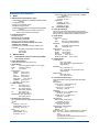
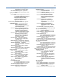
Electrical Parameters (Ex ia)
Each housing assembly (base module) and each
sensor module are respectively certificated.
Input parameters of sensor module meet output
parameters of housing assembly.
Housing assembly
Input
parameters
Output
parameters
Supply and output circuit (terminals + and -):
Ui, Vmax = 30 V
Ii, Imax = 100 mA
Pi, Pmax = 0.75 W
Ci =13 nF
Li = 0 mH
(Linear source)
Measuring module input circuit (CN2 or CN3 on
Back board)
Uo Vt, Voc = 13.65 V
Io, It, Isc = 50 mA
Po = 0.372 W
Co, Ca = 80 nF
Lo, La = 7.7mH
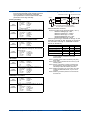
pH/ORP module, SC module, and DO module
Input
parameters
Ui, Vmax
Ii, Imax Pi, Pmax
Ci Li = 13.92 V
= 50 mA
= 0.374 W
= 40 nF
= 2.9 mH
Output
parameters
Sensor input circuit (pH: terminals 11 through
19, SC: terminals 11 through 16, DO: terminals
11 through 18)
Uo Vt, Voc = 11.76 V
Io, It, Isc = 116.5 mA
Po = 0.3424 W
Co, Ca = 100 nF
Lo, La = 1.7mH
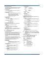
ISC module
Input
parameters
Ui, Vmax
Ii, Imax Pi, Pmax
Ci Li = 13.92 V
= 50 mA
= 0.374 W
= 40 nF
= 7.7 mH
Output
parameters
Sensor input circuit (terminals 11 through 17)
Uo Vt, Voc = 11.76 V
Io, It, Isc = 60.6 mA
Po = 0.178 W
Co, Ca = 100 nF
Lo, La = 8 mH
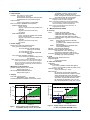
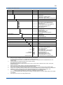
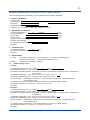
Control Drawing (ATEX and IECEx types)
Hazardous Location ← → Non Hazardous Location
Sensor 1
Sensor 2
Measuring module 1 Supply +
Housing Assembly
Measuring module 2 Supply -
+
Safety Barrier
(Note 1)
-
(*)
Note: The measuring module on this drawing means
the sensor module on this General Specifications.
Electrical data are as follows;
Supply and output circuit (Terminals Supply + and –):
Maximum Voltage (Ui) = 30V
Maximum Current (Ii) = 100mA
Maximum Power (Pi) = 0.75W
Internal Capacitance (Ci) = 13nF
Internal Inductance (Li) = 0mH
Sensor input circuit (pH: terminals 11 through 19, SC:
terminals 11 through 16, DO: terminals 11 thourgh 18,
ISC: terminals 11 through 17, SENCOM: terminals
82, 83, 84, 86 and 87):
Type of Measuring Module
Maximum Voltage (Uo)
Maximum Current (Io)
Maximum Power (Po)
External Capacitance (Co)
External Inductance (Lo)
pH, SC and DO
11.76 V
116.5 mA
0.3424 W
100 nF
1.7 mH
ISC
SENCOM
11.76 V
5.36 V
60.6 mA 106.6 mA
0.178 W 0.1423 W
100 nF
31 µF
8 mH
0.45 mH
Note 1:In any safety barrier used, the output current
must be limited by a resistor “R” such that
Imaxout=Uz/R.
Note 2:The safety barrier shall be certified by notify body
EU as ATEX.
Note 3:When using non isolation barrier connect (*1) to IS
earthing system.
Note 4:Sensor 1 and Sensor 2 shall be of passive types
to be regarded as ‘simple apparatus’ or the ones
individually certified with relevant parameters.
Note 5:Measuring module 2 may not mounted. As for ISC
module and SENCOM module, only one can be
mounted.
Note 6:Measuring module is placed in an enclosure with
IP20 and over.
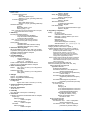
SENCOM Sensor module
Input
parameters
Ui, Vmax
Ii, Imax Pi, Pmax
Ci Li = 13.92 V
= 50 mA
= 0.374 W
= 40 nF
= 7.2 mH
Output
parameters
Sensor input circuit (terminals 82, 83, 84, 86
and 87)
Uo Vt, Voc = 5.36 V
Io, It, Isc = 106.16 mA
Po = 0.1423 W
Co, Ca = 31 µF
Lo, La = 0.45 mH
All Rights Reserved. Copyright © 2010, Yokogawa Electric Corporation
GS 12A01A02-01E Mar. 31, 2015-00