1
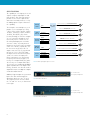
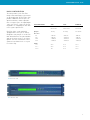
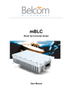
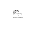
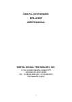
TIMING, TEST & MEASUREMENT ExacTime 6000 GPS Time & Frequency Generator • KEY FEATURES GPS Time and Frequency Reference • Disciplined Quartz Oscillator Time Base • Optional Disciplined Rubidium Oscillator • Rapid Acquisition and Time Stabilization • Six Programmable Output Signals • 1 PPS Time Interval Measurement to 1 Nanosecond • Automatic Daylight Savings Time Update • External Frequency Measurement to 10-14 • External Event Time Logging - Up to 256 Event Storage • Over 40 Signal Output and Function Options • RS-232 Input/Output Port • RS-232 Printer Port • INTRODUCTION Symmetricom’s ExacTime Time and Frequency Generators are full featured GPS receivers that offer three time base oscillator options and a wide range of “off-the-shelf” optional features. ExacTime fits virtually any GPS time and frequency application. The ExacTime 6000 is a 1.75" rack mount chassis that is configured to meet or exceed the demands of many applications, including test and measurement, metrology, range instrumentation and telecommunications. The extreme flexibility of this instrument allows configurations including time codes, low phase noise frequencies, pulse rates, parallel time and many other outputs to support specific needs. The internal quartz time base oscillator can be upgraded to an oven quartz oscillator or to a rubidium oscillator. A time zone offset control is included with 1/2-hour resolution, and a daylight saving time capability can be set for ten years. These controls affect the LCD display, time code output and the time in the RS-232 outputs. The year can be preset to any value for test purposes. For situations in which it is desirable to disable the oscillator disciplining process temporarily, a “flywheel” mode is provided. While in flywheel mode, the oscillator loop is opened, and the natural purity of the oscillator is not perturbed by the disciplining function. The ExacTime 6010 is a 3.5” rack mount chassis that is available to accommodate configurations that require more option space than is available in the ExacTime 6000 1.75” chassis. The basic unit provides six output BNC ports and one input BNC port. The six output ports are user selectable via box pin jumpers and front panel controls to generate frequency (10 MHz), pulse rates (1 PPM to 10 MPPS) and time code (IRIG B). Other frequency and time code outputs can be optionally added. A front panel LCD panel gives the user a simple and intuitive control interface. Remote control software for Windows is included upon request. Free Remote Control Software for Windows 95/98/2000 FIG.1 ExacTime GPS Time & Frequency Generator SPECIFICATIONS The capability of selecting any of several signals as inputs and outputs to and from the basic ExacTime unit make it possible to meet most requirements with a basic unit without the necessity for adding options. Figure 2 illustrates the capability. The four pulse rate multiplexers each produce a selected output of 1 PPM, .1 PPS, 1 PPS, 10 PPS, 100 PPS, 1 KPPS, 10 KPPS, 100 KPPS, 1 MPPS, 5 MPPS, 10 MPPS, IRIG B (DC), GPS status (Locked, Tracking), or +5 V. These outputs are selected either through the LCD menu or by remote control over the RS-232 input/output port. A 10 MHz sine wave can be chosen by internal jumper for any (or all) of the six output connectors. Likewise, IRIG B (AC) can be chosen for any (or all) of the six output connectors. The factory default function of J10 is 1 PPS (TTL) input for displacement measurement, but it can be selected as the input to the Event Log Counter or as an External Frequency Measurement input. J9 is factory set to output IRIG B (DC), while J8 is factory set to output IRIG B (AC). J6 is factory set to output Mux #3 digital signals with Mux #3 set to output 1 PPS. Finally, J5 and J4 can either be used to output GPS status or as duplicate outputs of Mux #2 and/or Mux #1. Event In / Frequency In / 1 PPS In (Time Interval) Event Log Counter Event J10 Input / Output Selector 10 MHz Out / IRIG B (DC) Out / Mux #1 Out J9 IRIG B Connector IRIG B (AC) IRIG B (DC) 10 MHz Out / IRIG B (AC) Out / Mux #2 Out J8 Pulse Rate Generator Mux #1 Mux #2 10 MHz Out / IRIG B Out / Mux #4 Out J7 Mux #3 Mux #4 10 MHz Out / IRIG B Out / Mux #3 Out (1PPS) J6 10 MHz Sine Wave Buffer 10 MHz 10 MHz Out / IRIG B Out / Mux #2 Out / Locked Out J5 Receiver Status FIG.2 Locked (TTL) Locked (Relay) Tracking (TTL) Tracking (Relay) 10 MHz Out / IRIG B Out / Mux #1 Out / Tracking Out J4 Defaults are in Bold Flexible input/output signal selection J11 = Printer Port Additional signal outputs are generated by the ExacTime 6000 through the option bay, which uses the “J3” area. The larger ExacTime 6010 uses both the “J3” and “J13” areas, as illustrated to the right. J12 = Input / Output Port FIG.3 ExacTime 6000 Back J11 = Printer Port J12 = Input / Output Port FIG.4 2 ExacTime 6010 Back E X ACT I M E 6 0 0 0 & 6 0 1 0 BASIC CONFIGURATION The two members of the ExacTime family of Time and Frequency Generators are pictured below. The ExacTime 6010 provides additional internal space for option installation, and also provides more rear panel space for input/output connectors. Please contact the factory for guidance in configuring the ExacTime to meet your requirements. ExacTime Units can be optionally equipped with a variety of Oscillators designed to suit your precise needs. The table below illustrates the part numbers and specifications for these Oscillator Options. For more information contact Symmetricom Global Services or your local Sales Rep. FIG.5 ExacTime 6000 FIG.6 ExacTime 6010 OSCILLATOR OPTION TCXO OCXO RUBIDIUM Part number ET6000-TCXO ET6000-OCXO ET6000-RB1 ET6010-TCXO ET6010-OCXO ET6010-RB1 1E-7/Day 5E-10/Day 5E-11/Month 1Hz -72dBc/Hz -94dBc/Hz -82dBc/Hz 10Hz -93dBc/Hz -115dBc/Hz -91dBc/Hz 100Hz -115dBc/Hz -136dBc/Hz -134dBc/Hz 1KHz -126dBc/Hz -144dBc/Hz -144dBc/Hz 1 Sec 2E-10 3E-11 3E-11 10 Sec 2E-10 2E-11 1E-11 100 Sec 1E-9 4E-11 3E-12 Aging rate Phase noise Stability 3 OPTIONS GUIDE 01 This guide is designed to assist the user in customizing the ExacTime Series 6000 Time and Frequency Generator. The BNC connectors on the rear panel can be configured to provide the outputs listed on the data sheet. The factory selections are: This option is described in detail in a separate data sheet. Three (3) simultaneous modulated time code outputs can be programmed with either the same or different time code formats. Option slots: 2 Prerequisite: Option 40 Connectors: J3A, B & C or J3D, E & F J4 = Tracking (TTL) J5 = Locked (TTL) J6 = 1 PPS (TTL) J7 = 10 MHz (sine) J8 = IRIG B (AC) J9 = IRIG B (DCLS, TTL) J10 = Time Interval Input (1 PPS, TTL) The ExacTime unit has a plug-in option motherboard with four (4) option pads (refer to the Option Motherboard, GPS Option 40x). Options are implemented with plug-in modules. The following information identifies all available options. Some option modules can be stacked together to provide additional functionality. However, stacking options sometimes requires the 2U chassis (ExacTime 6010, 3.5”/8.89 cm chassis height). Always consult the factory for assistance with stacked option configurations. 01A MULTIPLE TIME CODE OUTPUT 1 MHz SINE WAVE OUTPUT The 1 MHz Sine Wave output is derived from the internal disciplined oscillator by frequency division. The long term accuracy and stability is the same as the internal crystal oscillator. Option slots: 1 Prerequisite: Option 40 Connectors: J3A, B, D or E 07A 5 MHz SINE WAVE OUTPUT The 1 MHz Sine Wave output is derived from the internal disciplined oscillator by frequency division. The long term accuracy and stability is the same as the internal crystal oscillator. Option slots: 1 Prerequisite: Option 40 Connectors: J3A, B, D or E 08G -48 VDC POWER Negative 48 VDC input power is connected via a 4-pin nylon Molex connector. The input connections are completely isolated from the chassis and the signal ground the unit into the DC/DC converter power supply. Not available with Option 15A. Option slots: 0 Prerequisite: None Connectors: J1 FIG.6 FIG.7 4 10 to 32 VDC POWER DC input power is connected via a nylon Molex connector. The input connections are completely isolated from chassis and the signal ground of the the DC/DC converter power supply. Not available with Option 15A. Option slots: 0 Prerequisite: None Connectors: J1 MULTIPLE TIME CODE DC LEVEL OUTPUT If Option 01 is selected, this option provides DC level shift outputs for the output time codes. Option slots: 0 Prerequisite: GPS Option 01 Connectors: J3D, E & F (9390-6000) J13 (9390-6010) 06A 08CE 13A PARALLEL BCD OUTPUT (D-mS) Time is output by parallel BCD digits representing days, hours, minutes, and three digits of fractional seconds (millisecond resolution). The outputs standard HCMOS compatible. Each capable of sinking and sourcing 4 mA. Included in the output is a strobe signal is normally low, going high when the data is being updated, and going low the data is stable. This signal's falling can be used as a clock to load data external registers. Option slots: 2 Prerequisite: Option 40A (ET6000) Option 40 (ET6010) 14A IEEE-488 BUS INTERFACE This option provides the same remote control commands and responses as the standard RS-232 I/O. Option slots: 2 Prerequisite: Option 40D (ET6000) Option 40 (ET6010) Connectors: J3 (ET6000) J19 (ET6010) 20x LONG ANTENNA CABLE Cable type is Belden 9913 low loss cable with type N connectors at both ends. Option 20A = 100 foot cable Option 20B = 200 foot cable Option 20C = 300 foot cable Option slots: 0 Prerequisite: None ET6000 (1U chassis: 1.75”/4.44 cm) ET6010 (2U chassis: 3.5”/8.89 cm) E X ACT I M E 6 0 0 0 & 6 0 1 0 20x LONG ANTENNA CABLE Cable type is Belden 9913 low loss cable with type N connectors at both ends. Option 20D = 400’ (120 m) cable Option 20E = 500’ (150 m) cable Option slots: 0 Prerequisite: GPS Option 26B 21A 10 MHz SINE WAVE OUTPUT The 10 MHz Sine Wave output is derived directly from the internal disciplined oscillator. The long term stability is the same as the internal oscillator. Option slots: 1 Prerequisite: Option 40 Connectors: J3A, B, D or E 23x LIGHTNING ARRESTOR WITH CABLE The lightning arrestor option provides an inline unit that protects the GPS receiver from lightning surges. It is provided with 25 feet low loss cable. This option is desirable in lightning areas of the country. Connectors are Type N at both ends of the cable. Option 23A = 25’ (7.5 m) cable Option 23B = 50’ (15 m) cable Option slots: 0 Prerequisite: None 25 DC to 10 MHz BUFFER MODULE 33C E1 (2.048) FRAMED ONES OUTPUT One buffer module is required for each signal to be output (up to twelve). Twelve module sockets are provided on the Option 27A board. The module can accommodate a wide range of signals from DC to 10 MHz. It can be used for buffering pulse rates, time codes and frequencies. Many jumper selections are available under each buffer module socket. Option slots: 0 Prerequesite: Option 27A Provides an output of framed all ones E1 signal to operate in telecommunications systems typically outside the United States. The basic ExacTime will provide Stratum III performance, Stratum II with Option 10B, and Stratum I with Option 15A. Option slots: 2 Prerequisite: Option 40B (ET6000) Option 40 (ET6010) 27D 40x 1PPS PULSE BUFFER The 1PPS Pulse Buffer provides a 1PPS output at 10 volts peak into a 50Ω load as provided by most Cesium atomic standards. Option slots: 0 Prerequesite: Option 27A 33A 1.544/2.048 MHz SQUARE WAVE OUTPUT This module provides a square wave frequency output of either 1.544 MHz or 2.048 MHz (selected by DIP switch) that is phase locked to the internal disciplined oscillator. The basic ExacTime will provide Stratum III performance, Stratum II with Option 10B, and Stratum I with Option 15A. Option slots: 1 Prerequisite: Option 40 Connectors: J3A OPTION MOTHERBOARD This assembly provides the GPS unit with four option slots. It is required for most of the option modules described in this Configuration Guide. There is more than one version of this motherboard, so care must be taken to select the Option Motherboard that is required to support a particular option. Option slots: 0 Prerequisite: None RACK MOUNT SLIDES The ExacTime 6000 and 6010 are provided with rack mount flanges, but body support should be provided to avoid twisting the mounting flanges and front panel. This rack mount slide kit fits either chassis. The slides are furnished with hardware for mounting front and rear RETMA rails. Option slots: 0 Prerequisite: None 26B 27B 55144 HIGH GAIN GPS ANTENNA 33B T1 (1.544) FRAMED ONES OUTPUT Provides an output of framed all ones T1 signal to operate in telecommunications systems typically within the United States. The basic ExacTime will provide Stratum III performance, Stratum II with Option 10B, and Stratum I with Option 15A. Option slots: 2 Prerequisite: Option 40B (ET6000) Option 40 (ET6010) Connectors: J3A This antenna supports an antenna cable loss of up to 35dB. It is required for Option 20D (400'/120 m) or 20E (500'/150 m) antenna cables. Option slots: 0 Prerequisites: None 26C 55058-1 AIRBORNE GPS ANTENNA This antenna is required for all airborne installtions. The antenna connector is a miniature SMA type. A short type N-to-SMA adapter cable is furnished. Option slots: 0 27A TWELVE CHANNEL DISTRIBUTION BOARD This module is used in conjunction with Option 27B (required) to provide up to twelve buffered output signals on BNC connectors. The larger ExacTime 6010 chassis (3.5"/8.89 cm) is required to accommodate the additional BNC output connectors on the rear panel. Option slots: 0 Prerequisites: GPS Option 40 (ET6010) 5 ET6000 & ET6010 Specifications • • TCXO (standard): OCXO LPN (optional): Rubidium (optional): ELECTRICAL SPECIFICATIONS Outputs 10 MHz sinusoid: 1 PPS digital output: Selectable pulse rates: Time code: Status: +5 VDC LOCKED TRACKING 1 Vrms into 50Ω TTL level into 50Ω TTL level into 50Ω, 1PPM to 10 MPPS in decade steps, and 5 MPPS IRIG B into 50Ω, 3V P-P (AC & DC) IEEE 1344 compliant. Time code output is suppressed until accurate time is established. TTL* Relay** X – X X X X • • Keypad: • RS-232, 9-pin 'D' connector Year, time, status, position and interval at a programmed interval Time (D:H:M:S), CR on-time, every second Inputs 1 PPS time interval Signal: TTL level, pos or neg edge select Resolution: 1 nanosecond Accuracy: <10 nanoseconds External event log Signal: TTL level, pos or neg edge select Resolution: 100 nanoseconds Storage: Up to 256 events External frequency measurement Square wave: Logic "0" +0.2 ±0.2 VDC Logic "1" +2.4 to +15 VDC 1 Hz to 10 MHz Sine wave: 1 to 5 V P-P, 100 kHz to 10 MHz Offset range: nnnnX10-9 to nnnnX10-14 Autoranging • LCD, 2x40 characters. Displays time, status, satellite position data, frequency and control menu 0-9, Menu. Provides control of all functions ENVIRONMENTAL & PHYSICAL SPECIFICATIONS Temperature Operating **Relay N.O. Contact, 100 mA Format B: RS-232, 9-pin 'D' Front panel Display: • Aging: 1.0E-7/day Aging: 5.0E-10/day Aging: 5.0E-11/month Input/output Remote control and data output: *TTL level into 50Ω Printer outputs: Format A: Oscillator aging Unit: Antenna: Storage 0ºC to 50ºC -40ºC to 85ºC Unit: Antenna: Humidity -20ºC to 70ºC -55ºC to 100ºC Unit: Antenna: 0-95% relative, non condensing Unlimited • Power requirements: 85-264 VAC, 47-440 Hz, <40 watts • Dimensions H (in/cm) W (in/cm) D (in/cm) 1.75/4.45 3.5/8.89 17/43.18* 17/43.18* 12/30.48 12/30.48 ExacTime 6000: ExacTime 6010: *19/48.26 with rack mount ears • Standard equipment GPS Antenna 50’ (15 m) of RG58 antenna cable 18” (45.72 cm) antenna mast Complete antenna mounting kit User's manual Power cord GPS subsystem Time accuracy: Frequency accuracy: Position accuracy: Maximum velocity: After power-up, when LOCKED and using 200 position averages, will be better then ±125 nanoseconds relative to UTC with SA on within: 3 hour using Rubidium oscillator 2 hours using Oven oscillator 1 hour using TCXO oscillator 90% of time, better than: 1.0E-9 (TCXO) 1.5E-10 (OCXO) 1.0E-11 (Rubidium) 100m 2drms with SA. Less than 25m SEP without SA 515 meters/second (1,000 KPH) Tracking channels: 8 parallel Receiver frequency: L1, 1.575 GHz, C/A code Acquisition time: Typically <5 minutes to first fix. * See ExacTime Options Guide for additional options and option details. SYMMETRICOM, INC. 2300 Orchard Parkway San Jose, California 95131-1017 tel: 408.433.0910 fax: 408.428.7896 [email protected] www.symmetricom.com ©2005 Symmetricom. Symmetricom and the Symmetricom logo are registered trademarks of Symmetricom, Inc. All other trademarks are the property of their respective companies. All specifications subject to change without notice. DS/ET6000-6010/D/0105/PDF