1
Model DR-4000
Instruction Manual
DataRAM 4
Part Number 100334-00
9Sep2009
© 2007 Thermo Fisher Scientific Inc. All rights reserved.
Specifications, terms and pricing are subject to change. Not all products are available in all countries. Please
consult your local sales representative for details.
Thermo Fisher Scientific
Air Quality Instruments
27 Forge Parkway
Franklin, MA 02038
1-508-520-0430
www.thermo.com/aqi
WEEE Compliance
This product is required to comply with the European Union’s Waste
Electrical & Electronic Equipment (WEEE) Directive 2002/96/EC. It is
marked with the following symbol:
Thermo Fisher Scientific has contracted with one or more
recycling/disposal companies in each EU Member State, and this product
should be disposed of or recycled through them. Further information on
Thermo Fisher Scientific’s compliance with these Directives, the recyclers
in your country, and information on Thermo Fisher Scientific products
which may assist the detection of substances subject to the RoHS Directive
are available at: www.thermo.com/WEEERoHS.
Thermo Fisher Scientific
WEEE Compliance
CONTENTS
Section No.
Page
WARRANTY
1.0
2.0
3.0
v
GENERAL DESCRIPTION
SPECIFICATIONS
USER GUIDELINES
3.1 Handling Instructions
3.2
3.3
3.4
3.5
1
3
7
7
Safety Instructions
7
8
Orientation During Operation
Air Sampling Guidelines
8
3.4.1 Area Monitoring
8
3.4.2 Ambient Air Monitoring
8
3.4.3 Extractive Sampling
9
Environmental Constraints and Certifications.... .... ........... .10
4.0
ACCESSORIES
4.1 Standard Accessories
4.2 Optional Accessories
11
11
11
5.0
INSTRUMENT LAYOUT
5.1 Front Panel
5.2 Rear Panel
5.3 Bottom Base
5.4 Carrying Handle
5.5 Sampling Inlet
13
13
17
18
18
18
6.0
PREPARATION FOR OPERATION
6.1 Battery Charging and Operation
6.2 Inlet Uncapping
6.3 Filter Cartridge Installation
6.4 Power Selector Switch
6.5 External Electrical Connections
6.6 External D.C. Power Operation
19
19
19
20
20
20
20
i
7.0
OPERATING MODES
7.1 Set-Up Mode
7.2 Run/Data Logging Mode
8.0
KEY SWITCHES AND SCREEN CURSOR FUNCTIONS
8.1 ON/OFF Key
8.2 Screen Cursor, Arrow and +/- Keys
8.3 ENTER, NEXT and EXIT Keys
9.0
START-UP PREPARATION
9.1 The Menu Screens
9.2
9.3
9.4
9.5
9.6
9.7
9.8
ZERO/INITIALIZE Operation
Selecting Logging Parameters
Selecting Set-Up Parameters
Review or Transfer Stored Data
Run Start
Run Termination
Resetting and Defaults
23
23
23
25
25
25
25
27
27
28
29
30
33
35
37
38
10.0
ANALOG SIGNAL OUTPUT
10.1 Analog Output Description
10.2 Analog Output Connection
39
39
39
11.0
ALARM
11.1 Alarm Description and Operation
11.2 Alarm Output Connection
41
41
41
12.0
MAINTENANCE
12.1 General Guidelines
12.2 Battery Charging and Cycling
12.3 Instrument Storage
12.4 Filter Replacement
12.4.1 HEPA Filter Cartridge Replacement
12.4.2 Analytic Filter Installation/Replacement
12.5 Cleaning of Optical Sensing Chamber
43
43
43
43
43
44
44
45
13.0
CALIBRATION
13.1 Factory Calibration
13.2 Field Gravimetric Calibration
49
49
49
14.0
COMMUNICATIONS WITH COMPUTER
14.1 Computer Hardware and Software Requirements
14.2 Software Installation Procedure
14.3 Communication Between DataRAM 4 and Computer
51
51
51
51
ii
14.4 Real-Time RS-232 Output
14.5 Serial Communications Protocols of the DataRAM 4
APPENDIX A
APPENDIX B
APPENDIX C
53
53
55
57
67
iii
Warranty
Seller warrants that the Products will operate or perform substantially in
conformance with Seller's published specifications and be free from defects
in material and workmanship, when subjected to normal, proper and
intended usage by properly trained personnel, for the period of time set
forth in the product documentation, published specifications or package
inserts. If a period of time is not specified in Seller’s product
documentation, published specifications or package inserts, the warranty
period shall be one (1) year from the date of shipment to Buyer for
equipment and ninety (90) days for all other products (the "Warranty
Period"). Seller agrees during the Warranty Period, to repair or replace, at
Seller's option, defective Products so as to cause the same to operate in
substantial conformance with said published specifications; provided that
(a) Buyer shall promptly notify Seller in writing upon the discovery of any
defect, which notice shall include the product model and serial number (if
applicable) and details of the warranty claim; (b) after Seller’s review, Seller
will provide Buyer with service data and/or a Return Material
Authorization (“RMA”), which may include biohazard decontamination
procedures and other product-specific handling instructions; and (c) then,
if applicable, Buyer may return the defective Products to Seller with all
costs prepaid by Buyer. Replacement parts may be new or refurbished, at
the election of Seller. All replaced parts shall become the property of Seller.
Shipment to Buyer of repaired or replacement Products shall be made in
accordance with the Delivery provisions of the Seller’s Terms and
Conditions of Sale. Consumables, including but not limited to lamps,
fuses, batteries, bulbs and other such expendable items, are expressly
excluded from the warranty under this warranty.
Notwithstanding the foregoing, Products supplied by Seller that are
obtained by Seller from an original manufacturer or third party supplier are
not warranted by Seller, but Seller agrees to assign to Buyer any warranty
rights in such Product that Seller may have from the original manufacturer
or third party supplier, to the extent such assignment is allowed by such
original manufacturer or third party supplier.
In no event shall Seller have any obligation to make repairs, replacements
or corrections required, in whole or in part, as the result of (i) normal wear
and tear, (ii) accident, disaster or event of force majeure, (iii) misuse, fault
or negligence of or by Buyer, (iv) use of the Products in a manner for which
they were not designed, (v) causes external to the Products such as, but not
limited to, power failure or electrical power surges, (vi) improper storage
and handling of the Products or (vii) use of the Products in combination
with equipment or software not supplied by Seller. If Seller determines
that Products for which Buyer has requested warranty services are not
Thermo Fisher Scientific
Warranty
covered by the warranty hereunder, Buyer shall pay or reimburse Seller for
all costs of investigating and responding to such request at Seller's then
prevailing time and materials rates. If Seller provides repair services or
replacement parts that are not covered by the warranty provided in this
warranty, Buyer shall pay Seller therefor at Seller's then prevailing time and
materials rates. ANY INSTALLATION, MAINTENANCE, REPAIR,
SERVICE, RELOCATION OR ALTERATION TO OR OF, OR
OTHER TAMPERING WITH, THE PRODUCTS PERFORMED BY
ANY PERSON OR ENTITY OTHER THAN SELLER WITHOUT
SELLER'S PRIOR WRITTEN APPROVAL, OR ANY USE OF
REPLACEMENT PARTS NOT SUPPLIED BY SELLER, SHALL
IMMEDIATELY VOID AND CANCEL ALL WARRANTIES WITH
RESPECT TO THE AFFECTED PRODUCTS.
THE OBLIGATIONS CREATED BY THIS WARRANTY
STATEMENT TO REPAIR OR REPLACE A DEFECTIVE PRODUCT
SHALL BE THE SOLE REMEDY OF BUYER IN THE EVENT OF A
DEFECTIVE PRODUCT. EXCEPT AS EXPRESSLY PROVIDED IN
THIS WARRANTY STATEMENT, SELLER DISCLAIMS ALL
OTHER WARRANTIES, WHETHER EXPRESS OR IMPLIED, ORAL
OR WRITTEN, WITH RESPECT TO THE PRODUCTS,
INCLUDING WITHOUT LIMITATION ALL IMPLIED
WARRANTIES OF MERCHANTABILITY OR FITNESS FOR ANY
PARTICULAR PURPOSE. SELLER DOES NOT WARRANT THAT
THE PRODUCTS ARE ERROR-FREE OR WILL ACCOMPLISH
ANY PARTICULAR RESULT.
Warranty
Thermo Fisher Scientific
1.0
GENERAL DESCRIPTION
The DataRAM 4 (for Data-logging Real-time Aerosol Monitor 4), model DR-4000 is a
technologically advanced instrument (embodies U.S. Patent No. 6,055,052)
designed to measure the concentration of airborne particulate matter (liquid or solid),
as well as mean particle size, air temperature and humidity, providing direct and
continuous readout as well as electronic recording of the information.
The DataRAM 4 is the result of many years of field experience acquired with
thousands of units of its well known predecessors, the model RAM-1 and its
successor, the DataRAM, and embodies many technological advances made
possible by the latest electronic hardware and software.
The DataRAM 4 is a high sensitivity, two-wavelength nephelometric (i.e.
photometric) monitor whose light scattering sensing configuration has been
optimized for the measurement of the fine particle fraction of airborne dust, smoke,
fumes and mists in ambient, atmospheric, industrial, research, and indoor
environments.
The DataRAM 4 is a compact, rugged and totally self-contained instrument designed
for portable, as well as unattended fixed-point operation. It is powered by its internal
rechargeable battery, or by an AC power supply/charger (included as standard
accessory).
In addition, the instrument automatically checks its own optical background during
the zeroing sequence and indicates any significant deviations requiring
maintenance.
The DataRAM 4 covers a wide measurement range: from 0.0001 mg/m3
(0.1 µg/m3) to 400 mg/m3, a 4 million-fold span, corresponding to very clean air up
to extremely high particle levels.
In addition to the auto-ranging real-time concentration readout, the DataRAM 4
offers the user a wide range of information by scrolling its four-line LCD screen. This
information includes: median particle diameter, scattering coefficient, Ångström
coefficient, visual range, run start time and date, time averaged concentration,
elapsed run time, maximum with time of occurrence, air temperature and relative
humidity, etc. Operating parameters and diagnostic information screens can also be
displayed.
Furthermore, the DataRAM 4 features complete, large capacity internal data logging
capabilities with data retrieval on screen or through an externally connected
computer. The stored information (up to 50,000 data points) includes individual point
averages, particle size, temperature and humidity with time information as well as
overall average and maximum concentration, and tag numbers.
1
Selectable alarm levels with built-in audible signal as well as switched and signal
outputs, RS-232 and RS-485 communications ports, and a programmable analog
(voltage and current) concentration output are all part of this versatile instrument.
A custom software package is provided with the DataRAM 4 for communications to
and from a PC.
2
2.0
SPECIFICATIONS
Concentration measurement range (auto-ranging)1:
0.0001 to 400 mg/m3
Precision/repeatability (2-sigma)2,3:
± 1% of reading or ± 0.001 mg/m3, whichever is greater (1-second averaging)
± 0.3% of reading or ± 0.0003 mg/m3, whichever is greater (10-second averaging)
Accuracy1:
± 2% of reading ± precision
Resolution:
0.1% of reading or 0.0001 mg/m3, whichever is greater
Scattering coefficient range:
10-7 to 0.4 m-1 (resolution: 3 significant digits, max.)
Visual range:
0.01 to 337 km (@ λ = 550 nm) (resolution: 3 significant digits, max.)
Ångström coefficient measurement range:
0.0 to 4.0
Particle sizing range (log-normal, σg = 2.0, m = 1.50):
0.04 to 4.0 μm
Temperature measurement range:
-15 to 60 C° (accuracy: 0.5 C°)
Relative humidity measurement range:
0 to 100% (accuracy: 2%, non-condensing, @ 25 C°)
Sampling flow rate range4:
1.0 to 3.0 liters/minute (accuracy2: 0.05 liters/minute; adjustability: 0.1 liters/minute)
Measurement/display integration time range4:
1 to 60 seconds (selectable in 1-second steps)
Measurement/display update frequency:
1/second
HEPA filter cartridge replacement frequency (typical):
< 1 per 5 years (@ < 1 mg/m3)
3
Alarm level adjustment range4:
Selectable over entire measurement range for any of the selected measurement
units (concentration, scattering coefficient or visual range)
Data logging averaging periods4:
1 second to 24 hours (selectable in 1-second increments)
Data logging memory capacity:
50,000 data points in up to 99 tags (data groups)
Programmable zeroing periods4:
1 to 168 hours (selectable in 1-hour increments; if enabled, logging period must be >
10 minutes)
Elapsed time readout range:
1 second to 100,000 hours (over 11 years), in seconds, minutes and hours
Digital communications:
RS232/RS485: full duplex, 9600 baud, software controlled, device filtered
Computer requirements:
IBM-compatible PC, 486 or higher (Pentium I or higher, preferred); Windows™95 or
higher; 8 MB memory or more
Analog outputs:
0 to 5 V and 4 to 20 mA, with selectable full scale ranges between 0.1 and 400
mg/m3
Power:
• Internal battery: rechargeable sealed lead-acid, 7.2 Ah, 6 V,
20-hour run time between charges (typical)
• AC line: universal voltage charger/power supply (included),
100 – 250 V, 50 – 60 HZ (CE marked)
Alarm outputs:
• Alarm switch: 0 to +30 VDC (off, open), 2.5 A (on, closed)
• Alarm signal: 0 V (off), 5 V (on) (1 mA maximum load current)
• Audio alarm (back panel): > 60 dB @ 1 m
Operating environment:
-10 to 50 C° (14º to 122º F), 10 to 95% RH, noncondensing
Storage environment:
-20 to 70 C° (-4º to 158º F)
4
Dimensions (maximum external, including handle and inlet fitting):
166 mm (6.54 in) H x 226 mm (8.90 in) W x 327 mm (12.87 in) D
Weight:
5.5 kg (12 lbs)
1
Referred to gravimetric reference calibration (NIST traceable) with SAE
Fine test dust (mmd = 2 to 3 μm, σg = 2.5, as aerosolized)
2
At 25 °C
3
For single wavelength concentration sensing
4
User selectable
5
6
3.0
USER GUIDELINES
3.1
Handling Instructions
The DataRAM 4 is a sophisticated optical/electronic instrument and should be
handled accordingly. Although the DataRAM 4 is very rugged, it should not be
subjected to excessive shock, vibration, temperature or humidity. As a practical
guideline, the DataRAM 4 should be handled with the same care as a portable CD
player. The DataRAM 4 must be protected from all forms of precipitation.
If the DataRAM 4 has been exposed to low temperatures (e.g. in the trunk of a car
during winter) for more than a few minutes, care should be taken to allow the
instrument to return to near room temperature before operating it indoors. This is
advisable because water vapor may condense on the interior surfaces of the
DataRAM 4 causing temporary malfunction or erroneous readings. Once the
instrument warms up to near room temperature, such condensation will have
evaporated. If the DataRAM 4 becomes wet (e.g. due to exposure to water sprays,
rain, etc.), allow the unit to dry thoroughly before operating it.
Whenever the DataRAM 4 is shipped, care should be taken in placing it in its
carrying case and repackaging it with the original cardboard box with the factory
provided padding.
3.2
•
•
•
•
•
•
•
•
•
Safety Instructions
Read and understand all instructions in this manual.
Do not attempt to disassemble the instrument. If maintenance is required,
return unit to the factory for qualified service.
The DataRAM 4 should be operated only from the type of power
sources described in this manual.
Shut off DataRAM 4 and any external devices (e.g. PC) before
connecting or disconnecting them.
Shut off DataRAM 4 before plugging in or disconnecting the AC power
supply.
Never operate the DataRAM 4 without one of its internal filters in place.
If the internal battery of the DataRAM 4 has been allowed to discharge
completely, recharge the battery for at least 30 minutes before operating
the DataRAM 4.
During battery charging the DataRAM 4 should not rest on its front (i.e.,
bottom up).
To change position (angle) of the carrying/support handle, the large
buttons on both sides of the handle must be pushed in at the same time to
release handle lock. Do not attempt to rotate handle without releasing its
lock.
7
3.3
Orientation During Operation
The DataRAM 4 can be operated and/or charged in any of three orientations or
attitudes:
• Horizontally (front panel vertical), resting on its 4 bottom rubber pads.
• Tilted with front panel up, resting on 2 rear rubber pads and locked down handle.
• Vertical (front panel horizontal, upwards) resting on 4 rear rubber pads.
3.4
Air Sampling Guidelines
Caution: The DataRAM 4 is not designed to sample highly corrosive aerosols
or solvent fumes
3.4.1 Area Monitoring
For typical area monitoring applications, the DataRAM 4 should be placed and
operated centrally within the area to be monitored, away from localized air currents
due to fans, blowers, ventilation intakes/exhausts, etc. This is to ensure
representative sampling within the area to be assessed.
3.4.2 Ambient Air Monitoring
For ambient (extramural) sampling/monitoring the following procedures and
precautions should be applied:
• The sampling inlet should be away and above any obstructions whose wake may
affect sampling representativeness. Typically, the inlet should be about 1 m (or
more) above ground or any major surface (e.g., roof).
• Under typical horizontally directed and variable wind conditions, the use of the
Omnidirectional Inlet, model DR-OSI, is required, otherwise particles with
equivalent (inertial) diameters larger than about 1 μm may not be sampled
representatively.
• At ambient relative humidity above 65% to 70% airborne particles are likely to
grow by accretion of water. If only the solid portion of the particulates is to be
measured, the use of the Temperature Conditioning Heater, model DR-TCH
should be considered, especially when monitoring under fog or water mist
conditions. On the other hand, the user should be aware that such heating of the
sample stream might result in the evaporation of some volatile and semi-volatile
particles of interest.
• The DataRAM 4 is not weatherproof. To operate the DataRAM 4 outdoors,
provisions must be made to protect it from environmental extremes such
temperatures beyond its specified range, and from any form of precipitation. A
small shelter or roof may be required, with a modicum of heating during the
winter.
8
3.4.3 Extractive Sampling
Two general types of extractive sampling occur: a) from a chamber/vessel/room, and
b) from a duct or stack. In the first case the air to be monitored is generally nearly
stagnant or gently stirred (by means of a fan or blower). The second case almost
invariably involves a directed flowing stream at typical speeds of 3 to 30 m/s (600 to
6,000 ft/min).
To sample either from an enclosure (assuming the DataRAM 4 is to be located
externally to that enclosure), or a duct/stack, a length of tubing can be used to which
the following guidelines should be applied:
• Minimize tubing length, especially horizontally running lengths.
• Minimize the number bends and angle of change in direction.
• Minimize tubing inner diameter thus maximizing transport velocity (a practical
lower limit of about 2 mm, or 0.08 in. ID is indicated for reasons of excessive
pressure drop).
• If possible, changes in inner diameter (at unions, couplings, etc.) should be
incremental in the direction of flow, i.e., the inner diameter should only increase
in the direction of flow.
• Use non-electrostatic tubing. Best is electrically grounded metal or conductive
plastic (black) tubing, Tygon™ is acceptable, and Teflon™ is not to be used.
For tubing lengths of up to 2 m (6 ft.), 6 mm ID (1/4 in. ID) plastic tubing with wall
thickness of 1/16 in. is a practical size which can be stretched over the DataRAM 4
inlet stem.
For enclosure monitoring, the sampling inlet should be at some distance from the
inner wall of the enclosure in order to ensure sampling representativeness. Typically,
a minimum of 20 or 30 cm (1 ft.) is advisable. If a particle precollector is required
(e.g., a cyclone) it should be used as the inlet to the tubing, within the enclosure to
be monitored. If there is any pressure difference between the interior of the
enclosure and the location of the DataRAM 4, its exhaust port (on rear panel) must
be connected by tubing to the enclosure, i.e., the air stream extracted from the
enclosure must be returned to it after passing through the DataRAM 4.
For duct/stack monitoring, a probe should be used whose inlet faces the direction of
the airflow. If particles in the stream are larger than about 1 μm, sampling should be
under isokinetic conditions, i.e., the velocity of the air entering the sampling inlet
should equal the air velocity in the duct/stack at that point. This can be achieved
using the Isokinetic Sampling Kit model RAM-ISN which, in combination with the
DataRAM 4 covers the range of about 3 to 30 m/s (600 to 6000 ft./min). As in the
case of enclosure monitoring, it is advisable to return the DataRAM 4 exhaust air
stream to the duct/stack in order to ensure proper internal flow conditions within the
instrument.
9
3.5
Environmental Constraints and Certifications
The DataRAM is designed to be reasonably dust and splash resistant, however, it is
not weatherproof. To operate the unit outdoors provisions should be made to protect
it from environmental extremes outside its specified range, and from any exposure
to precipitation.
The DataRAM 4 is certified for compliance with the electromagnetic radiation limits
for a Class A digital device, pursuant to part 15 of the FCC Rules. The unit also
complies and is marked with the CE (European Community) approval for both
immunity to electromagnetic radiation and absence of excessive emission
interference.
10
4.0
ACCESSORIES
4.1
Standard Accessories
The DataRAM 4 is provided to the user with the following standard accessories:
•
•
•
•
•
•
•
Soft-shell carrying case (model RAM-2-184-1))
Digital communications cable (model DR-DOC)
Communications software disk (model DR4-COM)
Universal AC power supply/charger (model RAM-2-183-1)
Standard filter cartridge (installed)(model MSA-95302)
Analytical Filter Holder (model RAM-2-182-1)
Instruction manual
4.2
Optional Accessories
The following optional accessories are available from Thermo Fisher Scientific for use
with the DataRAM 4:
•
•
•
•
•
•
•
•
•
•
•
Omnidirectional Sampling Inlet (model DR-OSI)
Temperature Conditioning Heater (model DR-TCH)
In-line Impactor Head (10 and 2.5 μm) (model DR-PM10/2.5)
Impaction Nozzle for 1 μm (model DR-PM1N)
Ambient Sampling Inlet Set (consists of DR-OSI, DR-TCH and DR-PM10/2.5)
Isokinetic Sampling Set (model RAM-ISN)
Sampling Dilution Unit (model DR-SDU)
Respirable Cyclone Precollector (model DR-RCP10)
Solar Power Supply (model DR-SOL)
External DC cable assembly (model DR-DCS)
Analog signal output cable (model DR-ANC
11
12
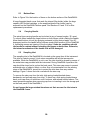
5.0 INSTRUMENT LAYOUT
The user should become familiar with the location and function of all externally
accessible controls, connectors and other features of the DataRAM 4. Refer to
Figures 1 through 3.
All user related functions are externally accessible. Qualified Thermo Fisher
Scientific personnel should perform all repair and maintenance. Please
contact the factory if any problem should arise. Do not attempt to disassemble
the DataRAM 4, except as described in Section 12.0 (Maintenance), otherwise
voiding of instrument warranty will result.
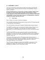
5.1
Front Panel
Refer to Figure 1 for location of controls and display.
The front panel contains the 10 touch switches (keys) and the LCD screen required
for the operation of the DataRAM 4.
The touch switches provide tactile ("popping") feedback when properly actuated.
The ON/OFF key serves only to turn on the unit (while it is in the off state), and to
turn it off (when it is operating). In the latter case, the DataRAM 4 switches
automatically to its internal purge mode for about one minute, and then shuts itself
off.
The EXIT and ENTER keys serve to execute specific commands that may be
indicated on the screen, and the NEXT key generally serves to scroll the displayed
information, e.g. to review the operating parameters that have been programmed,
diagnostic values, etc.
The four-line, 20-character per line LCD indicates either measured values of
concentration (instantaneous and time averaged on the same screen), elapsed run
time, and maximum values, operating and logging parameters, diagnostics,
command prompting or other messages.
The LCD screen is backlighted whenever the DataRAM 4 is powered by its AC
charger/power supply. When operating from the internal battery, the screen
backlighting is disabled in order to save battery charge.
13
14
15
16
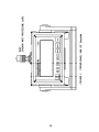
5.2
Rear Panel
Refer to Figure 2 for the location of items on the back panel of the DataRAM 4.
All components on the back panel are either labeled to indicate their respective
functions, or are self-explanatory. Viewing the back panel from the rear of the
DataRAM 4, the user should identify and become familiar with the following items:
•
•
•
•
•
•
•
•
•
The CHARGER/EXT. SUPPLY 3-pin male receptacle. The AC power
supply/charger provided with the DataRAM should be connected here whenever
the internal battery is to be recharged and/or when running continuously from the
AC line. Any other DC source (e.g., solar power supply, external battery, etc.) to
be used to power the DataRAM would be connected at this location.
Inlet cap storage pod. Directly below the charger/power supply connector is a
gray plastic pod provided for storage of the metal inlet cap whenever the
DataRAM 4 is in operation. The cap is snapped onto, or removed from the pod
by pulling the knurled sealing ring away from the opening of the cap.
The CE marking above the pod signifies that the DataRAM 4 has been certified
to satisfy all requirements that are implied in that marking (please consult with
Thermo Fisher Scientific about any questions on the CE certification).
To the right of the charger/ext. supply receptacle is the EXHAUST fitting. This is
the point where the sampled air exhausts from the DataRAM 4. This exhaust
airflow is particle-free as it has passed through the internal filter of the DataRAM
4.
To the right of the exhaust fitting is the ANALOG OUTPUTS signal connector.
Both 4 to 20 mA and 0 to 5 V outputs are available at that connector. In addition,
this connector also provides a VOLTAGE ALARM output (0 to 5 V).
At the upper right hand of the back panel is a 4-post connector. The upper two
binding posts provide a SWITCHED ALARM output activated whenever the
measured concentration exceeds a user set level (same as the voltage alarm
output). The lower two posts are for RS-485 communications.
Below the 4-post connector is a standard 9-pin male connector for RS-232
communications.
Directly to the left of the RS-232 connector is a 3-position switch provided for
POWER selection and shut off. To actuate this locking switch, pull its small
handle outwards while moving it up or down. In the mid position (handle
horizontal), the DataRAM 4 is shut off from any source of power, internal or
external. This position should be used for transport, or when the DataRAM 4 is
not to be used for an extended period of time. The upward position is for
normal operation, and should be used whether the DataRAM 4 is powered
from its internal battery, being charged or when powered from its AC
power supply. The downward position is only to be used when an external DC
source is applied (e.g., external battery, etc.).
In the lower right hand corner is a chassis ground post to which a grounding
connection may be made for fixed-point uses.
17
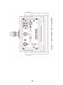
5.3
Bottom Base
Refer to Figure 3 for the location of items on the bottom surface of the DataRAM 4.
A large threaded plastic cover that seals the internal filter holder (either the large
capacity HEPA metal cartridge, or the analytical plastic filter holder) can be
accessed on the DataRAM 4 bottom panel. See Sections 6.3 and 12.4 for filter
replacement procedures.
5.4
Carrying Handle
The swivel-type carrying handle can be locked at any of several angles, 30° apart.
To unlock, press inwards the large buttons on both hinges, while rotating the handle.
Allow these buttons to lock (by springing outwards) at any desired angle. At a 90°
downward position the handle will provide an upward tilted position for the DataRAM
4, facilitating access and viewing of the front panel. Under no conditions should
the handle be rotated without unlocking the hinges on both sides. Otherwise,
the internal mechanism of the handle lock will be damaged.
5.5
Sampling Inlet
The sampling inlet of the DataRAM 4 is located on the upper face of the instrument.
This inlet is a quick-connect ¼-inch stem compatible with all inlet accessories
available. When the DataRAM 4 is not in use, the inlet should be closed by means of
the metal stem cap provided with the instrument. During DataRAM 4 operation this
cap should be stored on its pod on the back panel. This stem cap serves to prevent
accidental entry of objects, debris, or other form of contamination into the sensing
stage of the DataRAM 4, as well as to protect the inlet stem from any surface
damage. Figure 1 shows the inlet covered with the stem cap.
To remove the stem cap from the inlet, slide spring-loaded knurled sleeve
backwards, and pull cap away from inlet. To insert cap, slide spring-loaded sleeve
back, push cap down on inlet stem until it bottoms, and release knurled sleeve. The
same procedure applies when removing cap from or inserting it onto the storage pod
on the back panel of the DataRAM 4.
Do not loosen the large notched aluminum nut that secures the inlet stem to
the DataRAM 4 case.
18
6.0
PREPARATION FOR OPERATION
6.1
Battery Charging and Operation
The internal rechargeable battery of the DataRAM 4 is a sealed lead-acid gel-cell
type with very long lifetime. Under normal circumstances, the battery will provide
reliable operation for several years.
When shipped from the factory, The DataRAM 4 internal battery has been fully
charged allowing immediate operation of the instrument as received by the user.
Always recharge the battery after use and before storing the instrument for any
length of time. The battery of a stored instrument must be recharged at least every
three months.
If the DataRAM 4 has not been used for more than one month, it is advisable to
recharge its battery to full capacity before operating.
A fully discharged battery requires at least 12 hours of charging, using the supplied
charger, in order to attain full capacity.
A new and fully charged battery, at temperatures above 15°C (60°F), approx., is
expected to provide at least 20 hours of continuous operation.
During battery charging the DataRAM 4 can be placed in any of its operating
positions, but not resting on its front (upside down position).
If, while operating the DataRAM 4 from its internal battery, the battery charge were
to be nearly depleted such that its voltage drops below an acceptable level, the
DataRAM 4 will automatically switch to internal air purging and then shut itself off.
The DataRAM 4 can be operated continuously and for an indefinite time using its
universal charger/power supply. This charger/power supply accepts any line voltage
between 100 and 240 VAC, 50 to 60 Hz, without requiring any adjustments. When
using this charger/power supply, its connector should be plugged into and fastened
to the corresponding receptacle on the rear panel of the DataRAM 4 (see Section
5.2).
6.2
Inlet Uncapping
Before starting a measurement run, the protective stem cap must be removed
from the inlet and stored on the pod on the back panel (see Section 5.2). The
DataRAM 4 should never be in its run mode (pump operating) with the cap
covering the inlet.
19
6.3
Filter Cartridge Installation
Ensure that one of the two types of filter cartridges has been installed in the filter
chamber accessible from the bottom panel of the DataRAM 4 (see Figure 3). The
DataRAM 4 is shipped from the factory with the large capacity HEPA (High
Efficiency Particulate Air) filter cartridge in place. See Section 12.4.1 for procedures
to replace this cartridge or to install the analytic filter holder (Section 12.4.2). Except
when gravimetric measurements or chemical analysis of the filter collection
are to be performed, only the HEPA filter cartridge should be installed in the
DataRAM 4.
In order to gain access to the filter chamber, the large threaded plastic cap covering
the filter chamber must be rotated counterclockwise (as viewed from the bottom). Do
not leave this chamber open for any extended period of time, otherwise dust may
settle on the internal optical surfaces. Hand tighten the plastic cap firmly after filter
cassette replacement, to ensure a proper seal. At no time should the DataRAM 4
be running without a filter in place, otherwise serious damage to internal
components may result.
6.4
Power Selector Switch
When the DataRAM 4 is received from the factory, the 3-position power selector
switch will typically be in its OFF position (mid-position). To enable operation with
either its internal battery or with the charger/power supply provided with the
DataRAM 4, this switch must be placed in its INT. BATT. position (handle
upward). Refer to section 5.2 on how to operate this locking-type switch.
6.5
External Electrical Connections
Plugging in or unplugging any external equipment (e.g., computer, modem,
alarm circuitry, etc.) should be made only while both the DataRAM 4 and the
external equipment are shut off, in order to prevent damage or interference
due to transient electrical effects.
6.6
External DC Power Operation
If an external DC source of power is used, for example if AC power is not available
and continuous operation over more than 20 hours is required, an external battery or
other DC source (e.g., solar power) can be used.
If an external battery is used, its specifications are:
• Voltage: 6.0 to 9.0 VDC
• Instantaneous current capability: 3 A
• Continuous average current requirement: 300 mA
• To calculate the required ampere-hour capacity:
Ampere-hours = 0.3 x hours of operation
20
To connect external DC source to DataRAM 4, place 3-position POWER switch in its
OFF position. Use special cable assembly, Thermo Scientific model DR-DCS. Insert
its 3-pin connector into the CHARGER/EXT. SUPPLY receptacle on the rear panel
of the DataRAM 4 See Section 5.2 and Figure 2). Connect positive (+) side of
external battery to the lead marked (+), and the negative side (-) to the lead marked
(-). Once the connections have been completed, place the POWER switch in its
downward position (EXT. BATT.). Again, before disconnecting external battery,
return POWER switch to its OFF position.
21
22
7.0
OPERATING MODES
The DataRAM 4 has several different operating modes which will be described in
what follows. The specific commands and displays within each of these operating
modes will be explained in detail in Section 9.0
7.1
Set-Up Mode
The DataRAM 4 enters the Start-Up Mode as soon as the instrument is switched on.
The user then has the choice to:
a) Wait before proceeding;
b) Zero the instrument and check its readiness;
c) Review or export previously logged data;
d) Edit data logging parameters; or
e) Edit operating/measurement parameters
All parameter and status changes must be performed while in the set-up mode.
Once the DataRAM 4 is in the run (measurement) mode no changes can be made in
the parameters or status of the instrument.
While the DataRAM 4 is in the set-up mode the internal pump is not activated,
except while zeroing.
7.2
Run/Data Logging Mode
The Run Mode is the measurement/logging mode. The user can operate the
DataRAM 4 in this mode either with or without data logging. For example, the
instrument may be used first as a survey monitor without logging, for walk-through
assessment of an industrial plant, before deciding where to set up the unit for
continuous monitoring and logging. While in the run mode, the user will be able to
view all current measurement values, operating parameters, diagnostic status, as
well as any logged values up to that moment.
While the DataRAM 4 is in the run mode the internal pump is always activated.
23
24
8.0
KEY SWITCHES AND SCREEN CURSOR FUNCTIONS
Refer to Figure 1 showing the location of the front panel keys.
8.1
ON/OFF Key
The only function of the ON/OFF key is to switch the DataRAM 4 on or off depending
on whether the instrument is shut off or operating, respectively.
When keying ON (while instrument is off) the screen will display an identification
screen and then the MAIN MENU (see Section 9.1).
When keying OFF the screen will request confirmation by keying ENTER. If the
DataRAM 4 is in the run mode, this will then terminate the run and initiate the
automatic internal purging sequence with particle free air for about 1 minute, at the
end of which the DataRAM 4 will shut itself off. If the DataRAM 4 is not in the run
mode, keying OFF and then ENTER will also initiate the automatic purging sequence
followed by automatic shut off. In either case, keying EXIT instead of ENTER after
keying OFF cancels the termination command (the DataRAM 4 continues the run).
Regardless of whether the DataRAM 4 was in the run mode or any other mode when
shutting the unit off, all previously stored data remains in memory.
8.2
Screen Cursor, Arrow and +/- Keys
The cursor on the display screen is a blinking black rectangle marking a specific
function, status or parameter value that can be selected or modified. When the
cursor marks a > on the screen that specific function can be enabled by keying
ENTER.
To move the cursor from one line to the other on the screen use the ∨ or ∧ keys.
When the cursor marks the first letter of a status, that status can be toggled
(changed) by keying + or -.
When the cursor marks a digit of a parameter, the value of that digit can be
incremented by keying + or decreased by keying -. To move the cursor to the next
significant digit, either the < or the > keys should be used.
8.3
ENTER, NEXT and EXIT Keys
The ENTER key serves to implement or activate a specific function indicated by the
screen cursor, or when the screen display presents ENTER as a command
selection.
The NEXT key is used principally to go from one screen to the next either in the setup or in the run/logging mode.
25
The EXIT key is provided to initiate the run termination sequence, or to return to the
basic run screen (Run 1 screen) while the DataRAM 4 is in the run mode, to interrupt
zeroing, or to return to a previous screen.
26
9.0
START-UP PREPARATION
Please ensure that the rear panel power switch is in the upward position (see
Section 6.4).
9.1
The MENU Screens
Note: Bold, underlined symbols of the screens printed in this manual will denote
blinking cursor location (e.g., >).
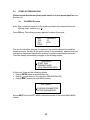
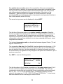
Press ON key. The following screen appears for about 5 seconds:
MIE
VER
S/N
DEV#
DataRAM 4
35
D376
1
The first line identifies the type of instrument, the second indicates the installed
firmware version, the third is the serial number of the instrument, and the fourth line
indicates an instrument identification number for serial communication purposes.
Then the display automatically changes to the following screen:
MAIN MENU
> START RUN
> ZERO/INITIALIZE
> VIEW/TRANSFER DATA
At this point, there are the following options:
• Keying ENTER starts a measurement run.
• Keying ∨ moves cursor to the next line (ZERO/INITIALIZE)
• Keying NEXT selects the next MENU screen:
EDIT MENU
> LOGGING PARAMETERS
> SETUP PARAMETERS
Keying NEXT from the EDIT MENU returns the screen to the initial MAIN MENU
screen.
27
9.2
ZERO/INITIALIZE Operation
Before initiating a measurement run it is advisable to perform the automatic zeroing
and internal check out sequences, to ensure optimal operation.
•
•
From the MAIN MENU select ZERO/INITIALIZE by moving the cursor to that line.
Key ENTER
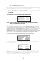
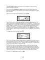
The pump starts up and the following screen appears initially:
ZEROING/INITIALIZING
COUNTDOWN:
194 sec
MEMORY LEFT:
100%
BATT. CHARGE
412 mA
NOTE: Specific numbers used in his manual are given only as examples;
values actually displayed may differ.
The time indicated on the second line is the countdown time required to complete
the automatic zeroing/initializing sequence. The MEMORY LEFT indication is the
unused percentage of the total logging memory. The BATT CHARGE reading is the
charging current when the DataRAM 4 is connected to the a.c. line through its
charger/power supply. If the charger is not used, that line on the screen will indicate
BATTERY LEFT, i.e., the percentage of charge still available from the battery.
A few seconds after the above display appears, the screen will go to:
ZEROING/INITIALIZING
COUNTDOWN:
186 sec
SOURCE 1:
NORMAL
SOURCE 2:
NORMAL
And finally to the following screen, indicating that the zeroing/initializing sequence
has been completed:
ZEROING/INITIALIZING
READY!:
0 sec
SOURCE 1:
NORMAL
SOURCE 2:
NORMAL
If the second line of the above screen indicates BACKGROUND HIGH instead of
READY!, it is probable that the lenses in the sensing chamber require cleaning.
Please refer to Section 12.2 for such cleaning procedures.
28
If the READY! message is displayed, return to the MAIN MENU by keying EXIT.
9.3
Selecting Logging Parameters
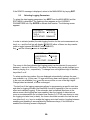
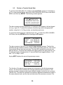
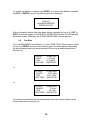
To select the data logging parameters, key NEXT from the MAIN MENU and the
EDIT MENU is displayed. The flashing cursor appears on the LOGGING
PARAMETERS line. Key ENTER to activate that function. The following screen
appears:
LOG DATA:
DISABLED
LOG PERIOD:
00:00:05
TAG #:
13
AUTO START: DISABLED
In order to activate (enable) the data logging function for the next measurement run,
key + or – and the first line will display ENABLED (either of these two keys can be
used to toggle between DISABLED and ENABLED).
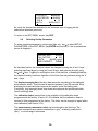
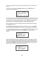
Key ∨ and the following screen is displayed:
LOG DATA:
ENABLED
LOG PERIOD:
00:00:05
TAG #:
13
AUTO START: DISABLED
The cursor in this line indicates that logging period can be selected (to any period
between 1 second to 24 hours). The value of the flashing digit can be changed up or
down by keying + or -, respectively. To change from one significant digit to another,
key either > or <.
To select another tag number (the one displayed automatically is always the next
one available, e.g., in this case, 12 tags would have been used already, and tag # 13
is the next one available), key ∨ and the cursor will be on one of the tag # digits.
Change/select as desired, or leave unchanged.
The last line of the logging parameters allows for programming a specific start time
and date for logging the data (the DataRAM 4 must be operating in the run mode to
effect such delayed logging). If the automatic start is disabled (as shown in the
above screen) and logging has been enabled, then the logging of data starts as
soon as a measurement run is initiated (see Section 9.6). If the user desires to start
the logging at a later time (or date), the cursor should be moved to the last line and
use either the + or – keys to enable the logging auto start function (toggling between
enabling and disabling is accomplished by these same keys). If this function is
enabled, the following screen is displayed:
29
LOG DATA:
ENABLED
LOG PERIOD:
00:00:05
TAG #:
13
AUTO:
16:25 JAN 17
As usual, the desired time and date for the automatic start of logging can be
selected as described previously.
To return to the EDIT MENU screen, key EXIT.
9.4
Selecting Set-Up Parameters
To select operating parameters, set time and date, etc., key ∨ to select SETUP
PARAMETERS on the EDIT MENU. Key ENTER and the first of 4 set up parameters
screen is displayed:
DISPLAY AVG:
10 SEC
CAL FACTOR:
1.00
UNITS:
(MASS) ug/m3
SIZE CORRECT: DISABL
As described before, the numerical values are changed by using the + and – keys,
selecting significant digits by using the > and < keys, and selecting lines by using
the∨ and ∧ keys. Toggling or scrolling the units of the third line, or enabling/disabling
the relative humidity correction algorithm of the fourth line are performed using the +
and – keys.
The display averaging time (first line) determines the smoothing of the displayed
measurement values. This time can be selected between 1 and 60 seconds. Short
averaging times provide faster response but noisier (more fluctuating) data.
Conversely, long averaging times slow down time response but provide smoother
(less fluctuating) data.
The calibration factor (second line) is the multiplier of the calibration slope
programmed at the factory. A factor of 1.00 indicates that the calibration slope is
identical to that programmed at the factory. This factor can be changed to agree with a
user calibration (see Section 13.2).
The measurement parameters (units) can be selected on the third line. The
selection alternatives are: mass concentration in μg/m3, scattering coefficient in
(Mm)-1, or visual range in kilometers.
30
The particle size correction refers to the computation of the mass concentration.
When this function is enabled, the measured mass concentration automatically takes
into account the volume median particle diameter determined in real time from the
ratio of the scattering irradiances at the two wavelengths of illumination of the
DataRAM 4. When this function is disabled, the monitor behaves as a single
wavelength (880 nm) nephelometer with its characteristic size dependence (similar to
that of the DataRAM, model DR-2000).
The second set up screen can be displayed by keying NEXT:
RH CORRECT: DISABL
TEMPERATURE UNITS: C
FLOW RATE: 2.00 LPM
The first line of this screen refers to the relative humidity correction. When this
function is enabled, the particle growth effect due to a high humidity environment is
corrected for. This means that the computed mass concentration is based on the
original dry environment particle population. This correction only applies when mass
concentration units have been selected, but not when scattering coefficient or visual
range has been selected.
The indicated temperature units can be selected between degrees Celsius (°C) and
degrees Fahrenheit (°F).
The air sampling flow rate of the DataRAM 4 can be adjusted over the range of 1.00
to 3.00 liters per minute (LPM). The nominal operating flow rate is 2.00 LPM. What
ever the selected flow rate, it will be maintained at a constant volumetric rate during
the measurement run regardless of any changes in the system flow resistance, up to a
maximum pump load.
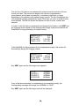
Key NEXT to view the following screen:
ANLG OUT:
4.00 mg/m3
SERIAL MODE:
RS-232
DEVICE #:
124
The first line refers to the full-scale concentration of the analog output signal (0 to 5
V and 4 to 20 mA) available at the back panel of the DataRAM 4. The full-scale
concentration ranges that can be selected (if mass concentration units are selected)
are: 0.1, 0.4, 1, 4, 10, 40, 100 and 400 mg/m3. If scattering coefficient units are
selected, the ranges are: 10, 100, 1,000, 10,000 and 100,000 (Mm)-1. If visual range
has been selected the full scale range is fixed at 500 km.
31
The serial mode of digital communication can be selected on the second line
between RS-232 and RS-485.
The last line is an identification number that the user can select to label this
particular DataRAM 4 for future reference. This number will accompany the logged
data information.
The next set up screen can be displayed by keying NEXT:
16:49:11
10 May 2000
TIME
16:48:55
DATE
10 May 2000
TO SET PRESS => ENTER
This screen is used to set the time and date, should these require resetting. The
first line indicates the time presently registered by the DataRAM 4. The second is the
time editing line. To set the time accurately, select a time (on the second line) that is
slightly ahead of the actual time (e.g., by 30 seconds) and select the seconds as a
multiple of 10. In the U.S., it is convenient to dial 1-900-410-8463 (U.S. Naval
Observatory time information), and at the instant when the time announced equals
the time preset on the second line of the above screen, key ENTER, as instructed on
the last line.
To display the next set up screen, key NEXT:
ALARM
ENABLED
LEVEL (ug/m3)
1000
AUTO ZERO
ENABLED
INTERVAL
48 hrs
The first line of the above screen allows enabling or disabling of the alarm function.
When the flashing marker is on that first line it is possible to toggle between those
two conditions by keying either + or -. The alarm level in the units of micrograms per
cubic meter can be selected on the second line.
The third line of the above screen allows enabling or disabling of the automatic
zeroing function whereby the DataRAM 4 automatically purges itself with particlefree air, and registers and then subtracts its optical background from all subsequent
measurements. The fourth line allows for the selection of the time interval in hours
(in one-hour steps up to 200 hours) between consecutive automatic zeroings.
To return to the MAIN MENU screen, key EXIT.
32
9.5
Review or Transfer Stored Data
To access stored data either for viewing on the DataRAM 4 screen or for transfer to
a PC or other external device, select the VIEW/TRANSFER DATA line on the MAIN
MENU, and then key ENTER. The following screen appears:
TAG # 12
> VIEW LOGGED DATA
> TRANSFER TEXT FILE
> DELETE LOGGED DATA
The above screen provides a selection of commands with respect to the last logged
run (e.g., tag # 12). To select the contents of another tag, select the appropriate
number, using the + - > < key strokes, as described previously.
To review the data logged for a selected tag #, key ∨ to select the VIEW LOGGED
DATA line, then key ENTER and the following screen appears:
TAG # 12
43 POINTS
START 11:23 09 May 00
END
11:27 09 May 00
LOG PERIOD
00:00:06
The above screen is the first of two available tag summary screens. The first line
identifies the tag # and the number of data points logged during that run. The second
line provides the run start time and date. The third line indicates the end time and
date for that run. The fourth line indicates the logging period use during that run. For
the above example, 43 data points of 6 seconds each were logged between 11:23
and 11:27 on May 9, 2000.
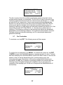
Keying NEXT displays the second tag summary screen:
TAG # 12
43 POINTS
AVG SCATR
0.00 1/Mm
MAX 207.33 11:23 09 May
AVG. DIA:
0.653 um
The first line of the above screen repeats the information of the first tag summary
screen. The second line indicates the average measured value for that run. This
average is given in whatever units were selected originally on the first set-up screen
(Section 9.4). The third line indicates the maximum registered instantaneous value in
the same selected units, and the time and date when this maximum occurred. The
33
last line indicates the average volume median particle diameter in micrometers for
that run.
In order to review the individual data points within a tag, key NEXT and the
following screen is displayed:
TAG # 12
POINT #
1
11:23:20 09 May 2000
171.46 1/Mm D = 0.40
um
TEMP = 28.0C RH = 40%
The first line indicates the tag # and the point # within that run, the second line is the
time and date of that point, the third line indicates the average measured valued and
the average volume median particle diameter for that logging period, and the last
line indicates the corresponding temperature and relative humidity values.
Keying + advances the point # scrolling the screens through all data points within
the selected tag # or run.
Keying NEXT returns the screen to the first tag summary table then, keying EXIT
returns to the VIEW/TRANSFER DATA screen (i.e., the first screen of this section).
In order to delete (erase) logged data, select the DELETE LOGGED DATA line from
the VIEW/TRANSFER DATA screen, and key ENTER. The following screen
appears:
DELETE LOGGED DATA
TAG # 01
> DELETE TAG DATA
> DELETE ALL DATA
Select either DELETE TAG DATA or DELETE ALL DATA, as preferred. In the first
case, only the data in the selected tag # are erased from memory, whereas in the
second case all stored data are erased. After the appropriate selection of the data to
be deleted, key ENTER, and the following screen is displayed (as an example it is
assumed that only the data of tag #1 are to be erased):
DELETING LOGGED DATA
TAG # 01
ENTER TO CONFIRM
EXIT TO CANCEL
34
To confirm the deletion command, key ENTER, or to rescind the deletion command,
key EXIT. If ENTER is keyed, the following screen is displayed:
TAG # 01
HAS BEEN DELETED
PRESS ANY KEY
After confirmation that the data have been deleted, pressing any key (e.g., EXIT or
NEXT) reverts the display to the DELETE LOGGED DATA screen if not all the data
have been erased. Otherwise, the VIEW/TRANFER DATA screen appears.
9.6
Run Start
From the MAIN MENU (see Section 9.1), select START RUN. When ready to initiate
the run, key ENTER, and one of the following types of screen appears (depending
on which measurement units were selected in the set-up procedure described in
Section 9.4):
16:08:09
CONC:
TWA:
RUN TIME:
10 May 2000
5.7 ug/m3
11.0 ug/m3
00000:02:25
16:08:09
SCATR:
TWA:
RUN TIME:
10 May 2000
10.33 1/Mm
6.83 1/Mm
00000:02:25
16:08:09
RANGE:
TWA:
RUN TIME:
10 May 2000
17.6 km
15.2 km
00000:02:25
or:
or:
It should be remembered that the measurement units can only be selected in the
set-up mode and not during a run.
35
The first line of the above run measurement screen shows the real time (24-hour
format) and date. The second line displays the real-time (instantaneous)
measurement value (mass concentration, or scattering coefficient, or range,
depending on the selected units) updated every second. The third line displays the
time-weighted average measurement value (TWA) from run start, in whatever units
were selected. The last line shows the elapsed run time in hours, minutes and
seconds.
In order to view the other run parameters and diagnostic information, key NEXT and
the following screen appears if the charger/power supply is not connected and the
DataRAM 4 is being powered by its internal battery.
MEMORY LEFT
87%
BATT. LEFT
76%
FLOW RATE
1.99 LPM
TEMP= 25.3C
RH= 59%
If the DataRAM 4 is being powered by its charger/power supply, this screen will
automatically display the charging current:
MEMORY LEFT
87%
BATT. CHARGE
326 mA
FLOW RATE
1.99 LPM
TEMP= 25.3C
RH= 59%
Key NEXT again and the following screen appears:
FLOW:
SOURCE 1:
SOURCE 2:
DETECTOR:
NORMAL
NORMAL
NORMAL
NORMAL
If any of the above functions or components is not operating correctly, the
corresponding message will change from NORMAL to FAULT.
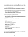
Key NEXT again and the following screen will be displayed:
36
SCATR PARAMETERS
PAR SCAT RATIO 0.5133
ANGSTROM COEF: 2.336
PARTIC. DIA:
0.454 um
The above screen shows the scattering parameters and the computed volume
median particle diameter in micrometers. The SCA RATIO value is the ratio of the
scattering irradiances detected at the two internal source wavelengths, i.e., at 880
nm and at 660 nm, respectively. If mass measurement units are selected (see
Section 9.4), the second line of the above screen will display PAR SCAT RATIO
which means that the indicated ratio is that due to particle scattering alone. If
scattering coefficient or visual range units have been selected (see Section 9.4), that
second line will read TOT SCAT RATIO, i.e., the ratio due to particle plus air
scattering. The Ångström coefficient is the exponent that defines the wavelengthdependence of the scattering irradiance. This coefficient varies between 4 for pure
Rayleigh scattering (molecular scattering), and 0 for wavelength-independent
geometric scattering.
9.7
Run Termination
To terminate a run key EXIT. The following screen will then appear:
TERMINATE RUN ?
TERMINATE:
CANCEL:
=> ENTER
=> EXIT
To confirm the run termination, key ENTER. To continue the current run, key EXIT.
If ENTER is keyed, the DataRAM 4 performs a purging operation for about 1 minute,
and then displaying the initial MAIN MENU screen from which a new run can then be
started. A new run can be started during the 1-minute purging cycle, thus
interrupting that cycle. Alternatively, if during this purging period (following run
termination) the OFF key is pressed, the purging operation will continue while the
following screen will appear indicating the countdown time in seconds for the
completion of the purging cycle. At the end of that period the DataRAM shuts off
automatically.
TURN POWER OFF ?
PURGING: 39
POWER OFF: => ENTER
CANCEL:
=> EXIT
37
If EXIT is keyed while the above screen is displayed, the MAIN MENU screen will appear
and remain after the purging has been completed. If the OFF key is then pressed the
DataRAM 4 will shut off without further purging since the instrument had already purged
itself.
9.8
Resetting and Defaults
The DataRAM 4 memory can be reset through commands entered on its keypad, as
follows:
•
•
•
Starting with the DataRAM 4 shut off, press the EXIT and ENTER keys at the same
time, and while holding down those two keys, press ON;
The screen will then indicate DataRAM 4 SELF-TEST followed in rapid succession
by several diagnostic screens, ending with TESTING COMPLETE;
Shut off unit. When turned on again, the DataRAM 4 memory will have been reset.
Resetting, as described above, accomplishes the following:
•
•
•
Erases all stored (logged) data from memory;
Resets all parameters and operating conditions to their default values and conditions
(see below); and
Cancels the zero correction offset.
The default values and operating conditions of the DataRAM 4 are:
•
•
•
•
•
•
•
•
•
•
•
•
•
•
•
Logging period (LOG PERIOD): 60 seconds
Logging status: disabled (LOG DATA: DISABLED)
Alarm level (LEVEL): 1 mg/m3
Alarm status: disabled (ALARM: DISABLED)
Analog output full scale: 1 mg/m3
Measurement units (UNITS): MASS
Calibration factor (CAL FACTOR): 1.00
Real-time display averaging time (DISPLAY AVG): 10 seconds
Flow rate: 2 liters/minute
Temperature units: C
Particle size correction ((SIZE CORRECT): disabled (DISABL)
Humidity correction (RH CORRECT): disabled (DISABL)
Auto zero: disabled (DISABL)
Serial port output format (SERIAL MODE): RS-232
Data output mode (DATA OUT): continuous
When turning on the DataRAM 4 after resetting the instrument, it will automatically go to
the zeroing mode. The DataRAM 4 will not measure (operate in the run mode) unless an
initial zeroing operation has been completed.
38
10.0 ANALOG SIGNAL OUTPUT
10.1 Analog Output Description
The DataRAM 4 incorporates the capability to provide both a voltage and a current
signal output directly proportional to the sensed concentration of airborne particulates.
Both these analog signal outputs are concurrently available. These outputs are provided,
principally, for fixed-point applications with hard-wired installations.
The particulate concentration range corresponding to the output voltage and current
ranges (0 to 5 V and 4 to 20 mA) can be user selected on the DataRAM 4 screen (see
Section 9.4) or via a PC using the communications software package included with the
instrument. The most sensitive range available is 0 to 0.100 mg/m3 (0 to 100 μg/m3), and
the least sensitive range is 0 to 400 mg/m3. For example, if the user selects the analog
output range of 0 to 0.400 mg/m3 then the analog output signal levels, at a concentration
of 0.200 mg/m3, would be 2.5 V and 12 mA.
This concentration range is independent of the digital display, data logging and real-time
digital output range which are controlled automatically (auto-ranging).
10.2 Analog Output Connection
For the 0 – 5 V output signal, the externally connected load must have an impedance of
more than 200 kilo-ohms. For the 4 – 20 mA output signal, the externally connected load
must have an impedance of less than 300 ohms.
Since both voltage and current outputs are present at the same time, both can be used
concurrently, if so required.
The accuracy of the analog output signals is better than 1% of the reading with respect
to the digital reading.
The 4 to 20 mA current output is available between pins # 1 and 4 of the 5-pin ANALOG
OUTPUTS connector on the back panel (see Section 5.2). The 0 to 5 V analog voltage
output is available between pins # 2 and 4 of that connector. Pin # 4 is common ground.
39
40
11.0 ALARM
11.1
Alarm Description and Operation
There are two alarm outputs available on the back panel of the DataRAM 4: a
switching alarm and a voltage alarm. The switching alarm output is capable of
sinking a current of up to 2.5 amperes to ground. The voltage alarm output goes
from 0 to 5 volts when the alarm is triggered. Whenever the alarm is triggered, the
on-board sound will be activated.
The alarm function can be enabled/disabled and the alarm level (trigger threshold)
can be selected by the user through the DataRAM 4 keyboard (see Section 9.4).
The alarm is triggered whenever the selected alarm level is exceeded. When the
displayed concentration falls below that level the alarm conditions stops. While the
alarm is on, the user can disable it momentarily by pressing any key on the
DataRAM 4. If the concentration continues to exceed the set alarm level after 10
seconds, the alarm condition will be reactivated.
11.2
Alarm Output Connection
There are two alarm outputs on the DataRAM 4:
a) Switching alarm. This alarm is available between the two upper terminals of the
4-terminal block on the upper right side of the back panel. The right-most
terminal is ground and the left terminal is normally open. When the alarm level is
exceeded, this latter terminal becomes grounded. A maximum load current of 2.5
A is allowed.
b) Voltage alarm. This alarm signal is available between pins # 3 and 4 on the
ANALOG OUTPUTS connector in the upper middle of the back panel. This
output consists of a voltage that steps from 0 to 5 V whenever the alarm is
triggered. The minimum external load impedance for this output is 10 kilo-ohms.
41
42
12.0
MAINTENANCE
12.1
General Guidelines
The DataRAM 4 is designed to be repaired at the factory. No user serviceable
components are inside the metal enclosure of the DataRAM 4 with exception of the
filter cartridge or the analytic filter holder. Access to the internal components of the
unit by others than authorized personnel voids warranty.
Unless a MALFUNCTION message is displayed, or other operational problems
occur, the DataRAM 4 should be returned to the factory once every two years for
routine check out, test, cleaning and calibration check.
12.2
Battery Charging and Cycling
If the DataRAM 4 is to be operated without its charger/power supply, i.e., deriving
power from its internal battery, this battery should be fully charged before initiating a
run. The DataRAM 4 charger/power supply can be connected continuously to the
instrument whether the DataRAM 4 is on or off. If the charger/power supply is not
connected, the internal battery will discharge very slowly depending on storage
temperature. Low storage temperature reduces battery capacity. High storage
temperatures, however, reduce battery life which is of the order of 8 years at 20°C
(68°F), and only 2 years at 40°C (104°F).
In general, the user should maintain the battery charge as high as possible in order
to extend its charge/discharge cycling capacity (this characteristic differs from that of
nickel-cadmium batteries).
12.3
Instrument Storage
If the DataRAM 4 is to be stored for an extended period of time (i.e., 3 months or
more), place the 3-position switch on the back panel in its OFF position (midposition), in order to minimize gradual battery discharge. This will have no effect on
data retention or internal clock function. It is recommended, however, that the
battery be recharged every 3 months in order to prolong battery life (see Section
6.1).
During storage always snap on quick-connect cap over the instrument inlet to protect
the sensing optics from gradual dust contamination. Store DataRAM 4 in a dry
environment.
12.4
Filter Replacement
To replace either of two types of filters used with DataRAM 4, place the instrument
on its back rubber feet (front panel facing upward). On the bottom surface of the
DataRAM, locate the large threaded plastic filter cover and holding the cross bar,
rotate this cover counterclockwise. Remove cover and the filter holder within the
open cavity.
43
12.4.1 HEPA Filter Cartridge Replacement
The DataRAM 4 is shipped from the factory with the HEPA filter cartridge installed.
This cartridge can be identified by its metallic cover. Remove this cartridge as
indicated in Section 12.4, above. Clean the internal black rubber gasket against
which the cartridge is normally compressed. Install new HEPA-type cartridge (part
no. MSA-95302) by inserting its wider ridged end first. Reposition threaded plastic
cover engaging threads carefully; rotate cover clockwise, hand tightening firmly.
Properly dispose of used cartridge to prevent inadvertent re-use.
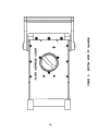
12.4.2 Analytic Filter Installation/Replacement
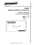
In order to install or replace the analytical filter holder, proceed as follows.
Remove the HEPA cartridge normally in place, as described in Section 12.4.1.
Remove (separate) the inlet cover (with the blue plug) of the Millipore plastic filter
holder from the rest of that holder assembly containing the white membrane filter.
Insert firmly the gray plastic adapter annulus into the open face of the filter holder
assembly, as shown in Figure 4. Remove the red plastic plug from the exhaust
nipple of the filter holder assembly. Ensure that all three components of the holder
assembly are fully compressed to preclude any leafage. Insert the assembly into the
filter cavity of the DataRAM 4 with the gray plastic adapter annulus bearing against
the internal black gasket (adapter annulus inserted first). Reposition threaded plastic
cover and hand-tighten carefully and firmly. Set aside HEPA cartridge for future use.
In order to remove and/or to replace the membrane filter within its holder, remove
the gray plastic adapter annulus and separate (pry apart) the two transparent plastic
rings that compress the membrane filter. Make sure to remove and replace only the
membrane filter (using tweezers), leaving the white backing disc in the holder. A new
membrane filter should then be placed over that backing and the sealing ring should
then be inserted to trap and compress the filter and backing discs. For storage, the
inlet cap with the blue plug should be inserted as well as the red plug on the back of
the filter holder.
44
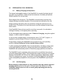
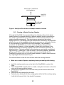
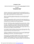
DIRECTION OF INSERTION
INTO DataRAM 4
ADAPTER
ANNULUS
FILTER AND
BACKING
Figure 4. Analytical filter holder with adapter annulus inserted
12.5
Cleaning of Optical Sensing Chamber
Although the DataRAM 4 incorporates filtered air shielding of the critical optical
sensing surfaces, continued sampling of airborne particles at high concentrations
may result in gradual build-up of contamination on those interior surfaces of the
sensing chamber components. This may cause an excessively high optical
background level. If this background level does becomes excessive, the DataRAM 4
will alert the user at the completion of the zeroing sequence, as indicated in Section
9.2 by the display of a BACKGROUND HIGH message. If this message is
presented, the DataRAM 4 can continue to be operated providing accurate
measurements. However, it is then advisable to clean the front surfaces of the
optical lenses within the sensing chamber at the first convenient opportunity, as
described below. The tools required for this cleaning are: an intense concentrated
light source (e.g., flash light) to view the inside of the sensing chamber, denatured
alcohol, a soft lint-free cloth, and the special cleaning tool provided with the
DataRAM 4 consisting of a cut-off cotton swab inserted in a plastic sleeve and held
by a right-angle Allen wrench (see Fig. 5).
Proceed as follows to clean the lens surfaces within the sensing chamber:
•
Make sure to shut off power completely before proceeding with cleaning
•
Install the stainless steel cover on the inlet of the DataRAM 4 to protect this
fitting.
Place the DataRAM 4 upside down on a table, resting the instrument on the inlet
cover and the rear protective bumper.
Unscrew the gray plastic cover of the filter cavity on the bottom surface of the
DataRAM 4.
Remove the filter cartridge from its cavity.
Carefully clean the black soft filter-sealing gasket within the filter cavity by wiping
it with the lint-free soft cloth. Use alcohol if necessary.
•
•
•
•
45
•
•
•
•
•
•
•
•
•
Shine the concentrated light source into the sensing chamber located about 3 cm
(1¼ in.) beyond the soft-sealing gasket in the filter cavity.
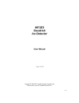
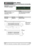
Using the layout of the Figure 5 as a guide, locate the three smaller side cavities
inside the sensing chamber, identified by the arrows on that figure. These three
cavities contain the lenses of the two sources and the common detector of the
DataRAM 4. The frontal surfaces of these lenses are likely to require cleaning if
the instrument indicates BACKGROUND HIGH.
Wet the cotton swab of the lens-cleaning tool with alcohol (e.g., methanol,
ethanol, or rubbing alcohol).
Holding the cleaning tool by its long handle, insert this tool into the sensing
chamber without touching the walls of this chamber.
Direct the cotton swab tip towards the opening of one of the three smaller
cavities as indicated by the arrows of Figure 5, and insert the cotton tip into this
cavity as far as it will go. Gently wipe that internal surface touched by the swab
tip by a rotating motion. Carefully withdraw the swab tip from the cavity.
Repeat previous cleaning step for the other two small cavities as indicated by the
arrows of Figure 5.
Carefully remove the cleaning tool from the sensing chamber. Allow the alcohol
to dry leaving the filter cavity open for about 15 minutes.
Re-insert the filter cartridge into its cavity and close it with its gray plastic cover,
hand-tightening it firmly. Remove the inlet cap and store on its pod on the back
panel.
Place the DataRAM 4 right side up and key ON. Proceed to check its optical
background by running the ZERO/INITIALIZE check as described in Section 9.2.
The message READY! should appear at the end of this check indicating that the
lens contamination has been eliminated. Should the message BACKGROUND
HIGH persist after completion of the above-described lens cleaning procedure,
please contact the factory.
46
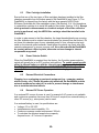
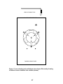
LENS CLEANING TOOL
DataRAM 4 FRONT PANEL
DataRAM 4 BACK PANEL
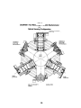
Figure. 5. Lens cleaning tool and bottom view of open filter cavity showing
location of sensor chamber lens cavities (arrows).
47
48
13.0 CALIBRATION
13.1 Factory Calibration
For mass concentration measurements, each DataRAM 4 is factory calibrated
against a set of reference monitors that, in turn, are periodically calibrated against a
gravimetric standard traceable to the National Institute of Standards and Testing
(NIST).
The primary factory reference method consists of generating a dust aerosol by
means of a fluidized bed generator, and injecting continuously the dust into a mixing
chamber from which samples are extracted concurrently by two reference filter
collectors and by two master real-time monitors that are used for the routine
calibration of every DataRAM 4.
The primary dust concentration reference value is obtained from the weight increase
of the two filters due to the dust collected over a measured period of time, at a
constant and known flow rate. The two master real-time monitors are then adjusted
to agree with the reference mass concentration value (obtained from averaging the
measurements of the two gravimetric filters) to within ±1%.
Three primary, NIST traceable, measurements are involved in the determination of
the reference mass concentration: the weight increment from the dust collected on
the filter, the sampling flow rate, and the sampling time. Additional conditions that
must be met are: a) suspended dust concentration uniformity at all sampling inlets of
the mixing chamber; b) identical sample transport configurations leading to reference
and instrument under calibration; and c) essentially 100% collection efficiency of
filters used for gravimetric reference for the particle size range of the test dust.
The test dust used for the factory calibration of the DataRAM 4 is SAE Fine (ISO
Fine) supplied by Powder Technology, Inc. It has the following physical
characteristics (as dispersed into the mixing chamber):
• Mass median aerodynamic particle diameter: 2 to 3 µm
• Geometric standard deviation of lognormal size distribution: 2.5
• Bulk density: 2.60 to 2.65 g/cm3
• Refractive index: 1.54
In addition to the mass calibration described above, the DataRAM 4 is factory
calibrated using a gas with known scattering coefficient in order to adjust the relative
scattering irradiance at the two source wavelengths.
13.2 Field Gravimetric Calibration
If desired, the DataRAM 4 can be calibrated gravimetrically for a particular aerosol
(dust, smoke, mist, etc.) under field conditions (actual conditions of use).
To effect such calibration in the particle environment of interest, proceed as
indicated below:
49
•
•
Weigh and load into the analytical filter holder a fresh membrane filter (see
Section 12.4.2).
Start measurement run.
The duration of this comparison run should be sufficient to collect a mass of at least
1 mg on the reference filter (in order to permit accurate weighing of the collected
mass by means of an analytical balance). The time-weighted average (TWA)
reading of the DataRAM 4 can be used to estimate the required sampling time to
collect the above-mentioned mass on the filter. To estimate the required sampling
time (RUN TIME as measured on the DataRAM 4) in minutes, read the TWA value
(see Section 9.6) after a RUN TIME of one minute or more, and apply the following
relationship:
RUN TIME ≥ 500/TWA
For example, if TWA = 2.5 mg/m3, then RUN TIME ≥ 200 minutes (approximately 3
hours). If the TWA value changes significantly as the run proceeds, recalculate the
required RUN TIME accordingly.
At the end of the run record TWA (in mg/m3), RUN TIME (in minutes), and the flow
rate Q (in liters per minute) used to sample the air. Weigh the filter on an analytical
balance and obtain Δm, the mass increment due to the collected particles. Calculate
the average gravimetric concentration C, as follows:
C = 1000 Δm / [(RUN TIME) x Q]
Compare the recorded value of TWA and the calculated value C, and calculate the
calibration factor to be programmed into the DataRAM 4 (see Section 9.0) as follows:
CAL FACTOR = C / TWA
For example, if C was found to be 3.2 mg/m3, and TWA had been determined to be
2.5 mg/m3, the CAL FACTOR equals 1.28. Select this value on the DataRAM 4
screen (or on the PC), as described in Section . This completes the gravimetric
calibration of the DataRAM 4 for a specific aerosol.
50
14.0
COMMUNICATIONS WITH COMPUTER
14.1
Computer Hardware and Software Requirements
The computer requirements to install and run the software provided with the
DataRAM 4 (DR4-COM) are the following:
•
•
•
•
•
•
•
IBM-PC compatible
Pentium I or higher processor
Minimum operating system: Windows 95™ or better
32 MB of RAM
8 MB hard disk drive
3.5” floppy drive
VGA or higher resolution monitor
The custom hardware and software provided with DataRAM 4 as standard
accessories:
•
•
Digital communications cable (model DR-DOC))
Software floppy disk (3.5”, model DR4-COM)
14.2
Software Installation Procedure
To install the provided software (DR4-COM) in the computer, proceed as follows:
•
•
•
•
Insert the 3.5” disk labeled DR4-COM into the computer;
Select Start and then Run on the computer screen;
Type in on the Command Line: a: install (or b: install, as required);
The computer displayed install shield then serves to guide the rest of the
installation.
14.3
Communication Between DataRAM 4 and Computer
To effect the communication between the DataRAM 4 (via the DR4-COM software
installed in the computer as described in the preceding section) and the PC proceed
as follows:
•
•
•
Connect the DataRAM 4 to one of the computer’s serial ports using the DR-DOC
cable provided. This cable has a 9-pin female connector for the computer port.
Key ON the DataRAM 4. Select the ZERO/INITIALIZE line on the MAIN MENU
screen and key NEXT to display the EDIT MENU screen. Then select the
SETUP PARAMETERS line and key ENTER. Key NEXT repeatedly until
SERIAL MODE appears. Select RS-232 if this has not been selected already.
On the computer, double click on the DR4-COM icon. A multi-tabbed notebook
display should appear on the computer screen. From the Menu Bar, select
Settings and Select Serial Port. Select the port to which the DR-DOC cable
51
has been connected. From the multi-tabbed notebook displayed on the computer
screen select the tab with the desired option. The options are:
♣ Main: This page allows the user to Device Filter and to operate the DataRAM
4 through the serial port;
♣ Logged data: This page allows the user to download, tabulate, print data, or
transfer to a CSV file the data stored in the DataRAM 4. This page also
serves to display real-time numerical data when the computer is connected
to the DataRAM 4 in the Run Mode of the instrument;
♣ Graph data: This page enables the downloading and graphing of stored data
to the computer screen and to a printer. In the Run Mode, this page displays
the real-time data in graphic format;
♣ Configure instrument: This screen allows the user to edit the
operating/logging parameters. Click on the item to be edited and select or
type in the new value. To review the parameter values currently programmed
into the DataRAM 4, click on Get configuration. After editing the
parameters, click on Set configuration to input the newly selected values
into the DataRAM 4.
♣ Communication settings: A DR4000 purchased after September 1, 2006
(Firmware version 105) will have a faster baud rate of 38400 bps. Prior to
September 1, 2006 (Firmware version 104) will have a baud rate of 9600
bps. Note: DR4Com Software (version 3.0.4.0) does have the ability to autodetect the instrument’s baud rate. Manual change may be accomplished by
going to Settings / Baud Rate and choosing 9600 or 38400.
Most operations with the DR4-COM software program are self-evidently labeled,
including fly-over dialog boxes. In addition, instructions may be found in the On-line
Help files by selecting Help and then Contents.
The following operating/logging parameters of the DataRAM 4 can be selected
(edited) via the computer:
•
•
•
•
•
•
•
•
•
•
Current date (year, month and day of the month)
Current time (hour, minute and second)
Display averaging time (1 to 60 seconds, in 1-second increments)
Calibration factor (0.01 to 9.99, in 0.01 increments)
Analog output full scale concentration (0.1, 0.4, 1, 4, 10, 40, 100, or 400 mg/m3
Analog output status (enabled or disabled)
Alarm level (0.001 to 409.5 mg/m3, in 1-μg/m3 increments)
Alarm status (enabled or disabled)
Particle size correction (enabled or disabled)
Humidity correction (enabled or disabled)
The serial number of the DataRAM 4 is transferred automatically to the PC and
displayed on the screen.
52
The year is to be entered as a two-digit number. Leap years are treated correctly
until the end of the 21st century.
14.4
Real-Time RS-232 Output
During the RUN mode the DataRAM 4 can communicate real-time concentration
data through its serial port via the DR4-COM software package. This software
application decodes the data and displays it on the computer screen in both
graphical and tabulated form.
In order to use this output with some other application, the following information will
enable the user to decipher the encoded output signal. The communication settings
for the digital output of the DataRAM 4 are:
•
•
•
•
•
Baud rate: 9,600/38400 Version 105 or later
Data bits: 8
Stop bits: 1
Parity: none
Flow control: Xon/Xoff
14.5 Serial Communications Protocols of the DataRAM 4
The DataRAM 4 has two serial ports. These are RS-485 or RS-232. Only one can be
active at a time. The active port is selected via the setup screen of the DataRAM 4
(see Section 9.4).
The RS-232 port is for direct connection of a single DataRAM 4 to a PC's comport as
described in Sections 14.1 through 14.4.
The RS-485 port is intended for connecting the DataRAM 4 to a "2-wire" network of
DataRAM 4's. If there is more than one DataRAM 4 on the network each unit will
need to have a unique device number. A PC can be attached to the network with a
RS-232/RS-485 interface. The PC will be the master and the DataRAM 4s are all
slaves. The interface needs to be set as DCE and support the T-RTS/R-~RTS
protocol. (The interface transmitter is turned on with RTS from the computer). The
RS-485 runs at 9600/38400 baud.
The communications protocol is the same for both RS-485 and RS-232. It is a TTY
type protocol. (i.e., not encoded; communication to a DataRAM 4 is performed with a
simple terminal program.) The master PC sends a single line command terminated
with a <cr>. A slave DataRAM 4 answers the command with possibly many lines,
ending with the signal character of ">". The master times out after 2 seconds if there
is no response from a slave.
53
The command format follows this general pattern:
<addr> <command> <parameter(s)> <cr>
<addr> is a numeric DataRAM 4 address, 1-125. Only the device named in the
address is allowed to respond. This address is required for a network setup. If there
is only one device on the network or if RS-232 is being used, then the addr can be
either blank or "0". Then that device will answer, whatever its number.
<command> is a one keyword command. The commands recognized are listed in
Appendix A. Mostly these pertain to setup variables in the DataRAM 4.
<parameters> depend on the command.
The response format will generally repeat the address and command and then follow
with the DataRAM 4's current settings.
For example:
♣
♣
♣
♣
The master PC sends: 27 backlight<cr>
DataRAM 4 #27 responds: 27 backlight enabled<cr>> (note the following ">")
The master PC sends: 27 backlight off<cr>
DataRAM 4 #27 responds: 27 backlight disabled<cr>>
54
APPENDIX A
LIST OF REMOTE DIGITAL COMMANDS
Informational commands(Read only):
battery
reports charge/discharge status: (battery charging 350 mA, or
battery discharging 65 pct)
display
get screen display (also: disp, d)
DataRAM returns:
This is a technical display:
V 5 21 "1st line of display" (20 chars long)
V 5 22 "2nd line ..
V 5 23 "3rd line ..
V 5 24 "4th line ..
V 5 25 (row of cursor) (col of cursor) (is cursor on?) (state number)
memory
get the percent of log memory available
output
if running, get current readings(also out, o):
e.g.: output 75.2 64.5 25.1 50. 0.435
for data, TWA, temperature, RH, and particle-diameter
temp
get current temperature (in tempunits selected) and humidity
(e.g.: temp 25.3 C 45: temperature in degrees C, 45% RH)
tags
get list of tags with data
Set/Get commands (Read or Write)
alarm
enable/disable, get/set value (mass in μg/m3, scat in 1/Mm, range in
km;
e.g.: alarm enabled 2000)
analogout get/set ANALOG_OUT range
For Mass concentration units:
0 for "0.10 mg/m3"
1 for "0.40 mg/m3"
2 for "1.00 mg/m3"
3 for "4.00 mg/m3"
4 for "10.0 mg/m3"
5 for " 40 mg/m3"
6 for " 100 mg/m3"
7 for " 400 mg/m3"
8 for "1000 mg/m3"
For Scattering units:
0 for " 10/Mm "
1 for " 100/Mm "
2 for "1000/Mm "
3 for "10000/Mm "
4 for "100000/Mm"
For Visual range units:
0 for "
500 km"
55
autostart Get/set auto start enable and date/time (e.g. enabled hh mm dd mm,
for hours, minutes, day, month)
autozero Enable/disable, value (e.g.: autozero enabled 1,
auto zero every hour)
calfactor Get/set CAL_FACTOR (e.g.: calfactor 1.0)
backlight Enable or disable the display backlight (e.g.: BACKLIGHT ENABLED)
date
Set/get Dataram date [e.g.: date 31 12 2001 (day, month, year)]
displayavg Get/set the display averaging time in 1 to 60 seconds
(e.g. diplayavg 10)
flowrate Get/set flowrate (e.g.: set flowrate to 2 LPM: flowrate 2.0)
logperiod Get/set log period in format hh mm ss (seconds, minutes, hours: 24
hours max)
rhcorrect Enable/disable Humidity correction (e.g.: rhcorrect enabled)
sizecorrect Enable/disable size correction (e.g. sizecorrect enabled)
tag
Set the tag number and enable(if empty)/disable logging
tempunits Get/set Temperature units in Celsius or Farenheit (e.g.: tempunits
F)
time
Set/get Dataram time [e.g.: time 23 59 59 (hours, minutes,
seconds)]
units
Get/set UNITS:
0 for “(MASS) ug/m3”,
1 for “(SCATR) /Mm ” and
2 for “(RANGE) km ”
Operational commands:
key
Send key (ie, button) pushes (enter, next, right, left…) to the DataRAM
onoff(1), exit(2), next(3), enter(4), plus(5), minus(6), up(7), down(8),
right(9), left(10)
The DataRAM will return: KEY and the numeric version of the key
requested or 0 if the key is not recognized.
Note: ‘display’ is useful in conjunction with the ‘key’ command.
tagdump
Transfer the tag data of the currently selected tag (see tag)
.
56
APPENDIX B
PRINCIPLE OF OPERATION OF THE DataRAM 4
General Description
The DataRAM 4 is a two-wavelength nephelometer (light scattering photometer) with
active air sampling (i.e., using an internal pump). The patented optical system (US
Patent No. 6,055,052) incorporates two sources of illumination (light emitting
diodes). One of these emits at a peak wavelength of 660 nanometers (red) and the
other at 880 nanometers (near infrared). The light beams from these two sources is
collimated by means of corresponding lens systems such that these beams
illuminate the same axial portion of the air flow duct. Figure 1B depicts the sensing
configuration of the DataRAM 4.
The axes of the two source beams are angularly symmetrical with respect to the axis
of a common detector (silicon-hybrid preamplifier type) that senses the light
scattered by particles passing through the illumination beams. The two sources are
alternatively activated at a frequency of 27 pulses per second, i.e., only one source
is turned on at a time. The detector output signal is gated in synchronism with the
alternating source pulses, providing two signal channels, one for each wavelength.
The scattering angle for both source-detector combinations is centered on 60° (±18°)
with respect to the forward direction of the two beams.
57
58
After these two beams traverse the sensing region within the flow duct, they enter
their respective light traps at the end of which there are corresponding reference
detectors that sense the intensity of each of the illumination beams. Feedback
circuits ensure that the light output of both sources remains constant.
The Effect of Particle Size
The magnitude of the detected light scatter at either of the two wavelengths is
directly proportional to the amount of particles passing through the sensing region of
the DataRAM 4, defined as the volume of intersection between the illumination
beams and the field of view of the common scattering detector. This response
linearity, however, assumes that the optical properties of the particle population
remain constant, i.e., that particle size and shape distributions, and effective particle
refractive index do not change appreciably∗. In practice however, and especially for
the fine particle fraction (PM2.5) in ambient environments, particle size can vary
appreciably over time and from site to site due to particulate emission and climatic
changes. The effect of particle size changes on the scattering signal depends on the
ratio of that size to the wavelength used to generate that scatter, and also on the
breadth of the size distribution.
Figure 2B shows the relative scattering signal (at the 660 nm wavelength) as a
function of the volume median particle diameter for several different geometric
standard deviations (σg, a measure of the spread of particle sizes) for single-mode
log-normally distributed particle populations, for an effective particle refractive index
of 1.50 (a typical value for ambient environments). This graph represents the
response (output) of the DataRAM 4 assuming constant particle volume
concentration (constant mass concentration for a given particle density) as a
function of the median size of the particle population being measured. Under most
practical situations, this population will not be monodisperse (geometric standard
deviation of 1.0) but will be polydisperse, i.e., will have a range of sizes with a single
or a multi-mode log-normal distribution. The fine particle fraction of ambient
environments (PM2.5) can usually be modeled by a single-mode log normal
distribution with a geometric standard deviation of 2.0 and a refractive index of
approximately 1.50 (for low relative humidity conditions). The response of the
DataRAM 4 to that population of particles is represented by the curve labeled 2.0 of
Figure 2B.
∗
Additional conditions that must be satisfied for response linearity are those of independent and
single scattering, both of which are fulfilled over the operating range of the DataRAM 4.
59
60
For an idealized mass monitor, the response curves of Figure 2B would be reduced
to a single horizontal line, implying that the measurement of mass concentration is
independent of particle size. The inherent behavior of light scattering (as modeled by
the rigorous Lorenz-Mie theory for spherical particles∗), however, precludes such
size independence. Alternatively, based on that size dependence and by measuring
the ratio of the responses at two different wavelengths it is possible to determine the
particle size and, consequently, to correct the mass measurement accordingly. This
capability has been incorporated in the DataRAM 4 and is intended to be applied to
fine particle monitoring, in combination with an inertial coarse-particle precollector
(e.g., impactor). This precollector removes the particle population (typically larger
than an aerodynamic diameter of 2.5 μm) whose size exceeds that of the fine
particle fraction.
When the particle size correction algorithm is enabled (the user has the option to
disable it), the DataRAM 4 computes the mass concentration as follows:
a) The scattering signal detected at the wavelength of 880 nm (after subtraction of
the zero particle concentration offset) is cross correlated with the corresponding
signal detected at 660 nm, and a combined signal is generated;
b) The ratio of the signals at 880 nm and at 660 nm is computed;
c) Based on the ratio determined in step b), the volume median particle diameter is
determined (from a stored look-up table derived from Lorenz-Mie calculations
based on the DataRAM 4 optical geometry and spectral sensing characteristics)
for a particle refractive index of 1.50 and a log-normal size distribution with a σg
of 2.0∗∗;
d) The particle size determined in step c) is then used to obtain the particle volume
(i.e., mass) correction factor (also stored as a look-up table); and
e) The above determined particle volume correction factor is applied to the
combined signal generated in step a) in order to compute the mass
concentration.
The equivalence between particle volume and mass used within the DataRAM 4 is
based on the calibration dust (SAE Fine) density of about 2.6 g/cm3 which is
representative of a wide range of particle materials in the environment. The user,
however, can select a different particle density scaling factor on the DataRAM 4 (i.e.,
the CAL FACTOR).
The DataRAM 4 performs the above discussed particle size computation in real time
on condition that the sensed mass concentration exceeds 0.005 mg/m3 (5 μg/m3). If
the concentration falls below that threshold, the DataRAM 4 performs this
computation and the size correction of the mass measurement based on the last
size determination that had been performed when the above concentration threshold
was exceeded.
∗
Field investigations indicate that the fine particulate fraction consists predominantly of spherical
particles
∗∗
For custom applications involving different refractive indexes and/or particle size distributions,
please consult Thermo Fisher Scientific
61
Scattering Coefficient, Visual Range and Ångström Coefficient
The fact that the DataRAM 4 incorporates the capability to measure the wavelength
dependence of the scattering of light by airborne particles allows the determination
of the atmospheric visibility effects of that population. These effects are customarily
referred to a standard wavelength of 550 nm, the approximate center of the photopic
response of the human eye as well as the peak of the solar irradiance spectrum.∗
The scattering coefficient is the primary parameter sensed by the light scattering
system of a nephelometer such as the DataRAM 4. This coefficient is a logarithmic
exponent that represents the degree of light attenuation due to scattering, per unit
path length, expressed in the units of inverse length (e.g., inverse megameters,
abbreviated as Mm-1). By measuring the scattering coefficient at two different
wavelengths it is possible to establish the wavelength dependence of that coefficient
and, consequently, calculate the scattering coefficient at the reference wavelength of
550 nm. This calculation is performed within the DataRAM 4 and this information can
be displayed/logged as measurement parameter in lieu of the mass concentration
data.
Based on the value of the measured scattering coefficient the DataRAM 4 then
computes what is called the visual range defined as the distance, under daylight
conditions, at which the apparent contrast between a specified target (usually a
black surface) and its background (horizon sky) becomes just equal to the threshold
contrast of the average observer. This dependence of the visual range on the
scattering coefficient assumes that light absorption by the particle population under
scrutiny is negligible compared to scattering. Although this assumption is not always
satisfied, for a majority of cases it constitutes an acceptable approximation. The
empirical relationship between the scattering coefficient sensed by the DataRAM 4
and the visual range is given by the Koschmieder equation. The visual range (in the
units of kilometers) can also be displayed/logged as measurement parameter in lieu
of either the mass concentration or of the scattering coefficient.
Finally, and based on the ratio of the detected irradiances at the two operating
wavelengths, the DataRAM 4 is programmed to compute the Ångström coefficient.
This coefficient is a dimensionless exponent that expresses the functional
relationship between the atmospheric scattering coefficient and the wavelength of
light, and is dependent on the size distribution of the fine particle fraction.
Theoretically, the Ångström coefficient varies over the range of 0 to 4. The limit
value of 4 is for scattering by particles whose size is much smaller than the
wavelength of visible light (Rayleigh or molecular scattering regime). The limit of 0 is
for particles larger than the wavelength of the illuminating light (geometric regime).
This coefficient can also be displayed on the DataRAM 4 screen, as a secondary
parameter.
∗
The near matching between these two peaks is generally attributed to an evolutionary selection
process
62
The Effect of Ambient Humidity
Fine airborne particles tend to accrete liquid water whenever the relative ambient
humidity is high. Therefore, particles grow in size as humidity increases. This growth
has been found to be generally negligible up to relative humidity (RH) levels of about
50%. At higher levels, especially over 70% this growth becomes very significant to
the point that the majority of the mass of the fine particulate matter is constituted of
water.
Figure 3B shows the relationship between the concentration measured by a
nephelometer (model DR-2000, DataRAM) and a collocated gravimetric sampler.
The curve is an interpolation of experimentally obtained field data. This curve shows
that below a RH of 50% the two devices agree whereas above that point the
nephelometer indicates a higher value which is the result of the humidity induced
particle growth mentioned above.
For atmospheric visibility measurements this high-humidity particle growth effect
must be included since the purpose of such measurements is to assess the actual
visual effects of airborne particles. For fine particle mass concentration
determinations, however, the accreted water interferes with the measurement of
interest, i.e., monitoring the mass of the original core particles. Gravimetric methods
require sample conditioning (post sampling drying) to eliminate the water accreted
by the collected particulate matter sample. Continuous mass monitors such as those
based on beta attenuation or on mechanical resonance have heretofore relied on
sample heating to enhance water evaporation. This later approach, however, not
only reduces the amount of interfering water but also causes partial evaporation of
semi-volatile particle components of interest, thus introducing a measurement error.
Other methods, such as diffusion drying can be applied without affecting the
measurement of semi-volatiles, but are inconvenient in their application to
continuous unattended ambient monitoring.
In the case of the DataRAM 4, the user has the option to activate an automatic
humidity correction that is based on the experimentally obtained curve of Figure 3B.
When the humidity correction process is enabled (by keystroke selection), the
DataRAM 4 applies a correction factor to the measured mass concentration that
depends on the relative humidity measured within the optical sensing chamber. For
example, if the sensed humidity were to be 80%, the DataRAM 4 without correction
would over-read by a factor of 1.8 with respect to a gravimetric sampler. If the
automatic humidity correction is enabled, the optically sensed concentration will be
internally multiplied by 1/1.8, or 0.56, in order to compensate for the humidity
induced particle growth. This correction is valid for most fine particle measurements,
but should not be applied to measurements of larger particle sizes. This correction
takes into account the change (decrease) in the refractive index of the grown
particles due to the predominance of water (with its lower index).
63
64
The particle size determination, based on the ratio of signals at the two DataRAM 4
wavelengths (discussed above) is not significantly affected by the change in
refractive index associated with the particle uptake of liquid water. In the PM2.5
range, a change of particle refractive index from the typical dry value of about 1.50
to that of pure water (1.33) causes a sizing error ranging from 0% for 0.1 μm
particles to 7% for 2.5 μm particles. The actual sizing error is likely to be smaller
since the refractive index of water-accreted ambient particles generally exceeds
1.40.
It is of interest to note that if the DataRAM 4 is used in conjunction with an in-line
sample stream heater (e.g., model DR-TCH), and the resultant measurements are
compared with the humidity corrected measurements mentioned above (without the
heater), it is possible to assess the loss of particle mass due to evaporation of semivolatile particles. Alternatively, if there were no difference between measurements
obtained with and without the inlet heater, it would indicate that there is no humidity
induced particle growth and thus, the humidity correction should not be enabled.
SERVICE LOCATIONS
For additional assistance, service is available from exclusive distributors worldwide.
Contact one of the phone numbers below for product support and technical
information or visit us on the web at www.thermo.com/aqi.
1-866-282-0430 Toll Free
1-508-520-0430 International
65
66
APPENDIX C
LIST OF DR-4000 Fault/Failure Error Codes
ERROR
CODE
DESCRIPTION
POSSIBLE CAUSE
(IF ERROR PERSISTS)
ACTION TO CORRECT
0000
0001
No Fault/Failure
Source 1 Fault/Failure
Damaged connector or obstruction
in Optics chamber.
Remove filter cap and check
for obstructions in the optical
path.
Remove filter cap and check
for obstructions in the optical
path.
Remove filter cap and check
for obstructions in the optical
path.
Use the HEPA filter whenever
the sample filter is not
required. To see if the HEPA
filter is clogged, try to run the
pump will run (less than a
minute) without the HEPA
filter.
0010
Source 2 Fault/Failure
Damaged connector or obstruction
in Optics chamber.
0100
Detector Fault/Failure
Damaged connector or obstruction
in Optics chamber.
1000
Pump Fault/Failure
Filter is clogged or pump is worn /
defective. Sampling contaminated
air without a filter or with a clogged
filter will shorten the life of the
pump.
Please note the four-bit code indicates whether or not one of four monitored signal
voltages was out of specification during a logged run. Because of signal noise,
eventually all four error bits will become set (“1111”) if the equipment is operated for
extended periods without performing a periodic zero cycle.
During a run, the DR-4000 switches to the DIAGNOSTICS display whenever an
error is detected. This is not necessarily an indication of instrument failure unless the
error(s) persists. Persistent faults displayed in the 'DIAGNOSTICS' display for longer
than 4 seconds indicate that an instrument may require service.
67
68