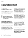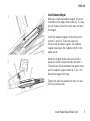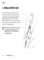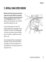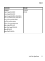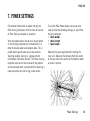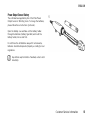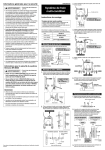
1
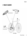
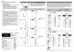
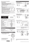
Power Output Sensor W.I.N.D.
User manual
ENGLISH
Contents
1. PRODUCT ELEMENTS........................
3
2. INTRODUCTION ..............................
4
3. INSTALL POWER SENSOR MAIN UNIT ......
Install Cadence Magnet .................
6
7
4. INSTALL BATTERY CASE ....................
8
5. INSTALL CHAIN SPEED SENSOR ............
9
6. VERIFICATION OF THE SENSOR
INSTALLATIONS ............................. 12
7. POWER SETTINGS ........................... 13
8. CUSTOMER SERVICE INFORMATION ........
Care and Maintenance ..................
Power Output Sensor Battery ...........
Frequently Asked Questions ............
Technical Specifications ................
Limited International Polar
Guarantee.................................
Disclaimer ................................
14
14
15
16
17
17
19
ENGLISH
1. PRODUCT ELEMENTS
Product Elements
3
ENGLISH
2. INTRODUCTION
The Polar Power Output Sensor system works by
measuring two key factors:
Together with the Polar training computer, Polar
Power Output Sensor measures
• Chain Tension - Power Output Sensor main unit
on the rear stay measures the tension of the
chain from the vibrations of the chain as it
passes over the sensor.
•
Actual, average and maximum Power values,
•
Left/Right Balance (distribution of power
between left and right legs),
• Chain Speed - Chain Speed Sensor on the rear
derraileur measures the speed of the chain
magnetically.
•
Pedaling Index (how even the power is
distributed during a crank arm rotation), and
•
Cadence
For information on power features of your training
computer, refer to the user manual of training
computer in question.
4
Introduction
ENGLISH
For training purposes, Power Output Sensor
provides much more precision than heart rate
measurement and perceived exertion. Power
measurements also have a number of other uses,
including bike positions and determining
efficiency at different cadences among others.
Polar Power Output Sensor is suitable only for
road bikes, ridden on tarmac. It is not suitable for
mountain bikes or bikes with very complex rear
stays.
For more instructions on how best to benefit from
the Power Output Sensor, refer to the user manual
of Polar training computer in question. The latest
versions of the user manuals can be downloaded
at www.polar.fi/support.
Introduction
5
ENGLISH
3. INSTALL POWER SENSOR MAIN UNIT
For a video tutorial, go to
http://www.polar.fi/en/support/video_tutorials.
To install the Power Output Sensor, you will need
10 mm wrench, 3 mm Allen key, a chain breaker,
scissors, measuring tape and rubber gloves.
Before installing the main unit, measure the
span length. For instructions, see Power Settings
for Polar Training Computer.
Disconnect the electric wires from the Power
Output Sensor main unit before installing. Attach
the main unit to the top of the right chain stay, so
that the wires are directed backwards. Position the
sensor just on the top of the chain stay, not
leaning to either side (picture 1), in such a way
that the dot on the upper side of the unit (picture
2 a) is exactly in the middle of the chain stay.
6
Install Power Sensor Main Unit
The ideal place for the sensor is as close to the
chain as possible without the chain touching it
(about 2mm/0.08”) in the small/small
chainring/cog combination. Depending on your
frame, it may be necessary to put supporting
pieces under the sensor. Note that there are
supporting pieces of three sizes in the set. Before
attaching the supporting pieces for the sensors or
the magnet to the bicycle, the area in question
should be cleaned and dried thoroughly.
The sensor should be attached directly under the
chain (picture 1). The measurement is most
accurate when the chain runs just over the
sensor's central axis. Make sure that the crank
doesn’t hit the unit when pedaled.
Pass the cable ties through the sensor holes and
around the chain stay. Do not wind them around
the gear cable. Adjust the ties loosely. Do not
tighten the cable ties of the sensor fully before
installing the cadence magnet.
ENGLISH
Install Cadence Magnet
When you install the cadence magnet, the chain
should be on the largest front chainring. This way
you can make sure that the chain does not touch
the magnet.
Install the cadence magnet inside of the crank
(picture 1 and 2 b). To ensure successful
transmission of cadence signals, the cadence
magnet should pass the "cadence notch" on the
power sensor.
Attach the magnet to the crank arm so that it
passes the sensor closely but does not touch it.
The maximum distance between the power sensor
and the cadence magnet should be 7 mm / 0.3".
Secure the magnet with tape.
Tighten the cable ties around the main unit and
cut off any excess ends.
Install Power Sensor Main Unit
7
ENGLISH
4. INSTALL BATTERY CASE
Attach the battery case to the seat stay, on the
same side of the bike as the power sensor main
unit (picture 3). Pass the cable ties through the
battery case holes and around the seat stay.
Tighten the cable ties and cut off any excess ends.
Also use cable ties to secure the battery case wire
so that it is not hanging loosely.
Choose the place for the Battery Case so that you
can easily take out the battery holder when
changing batteries. For more information, see
Care and Maintenance.
8
Install Battery Case
ENGLISH
5. INSTALL CHAIN SPEED SENSOR
Wind the wire from the power sensor to the chain
speed sensor securely around the rear derailleur
cable, or use cable ties to secure the wire so that
it is not hanging loosely. However, the normal
operation of the rear derailleur must be possible.
Avoid extreme tightening of the wire.
There are three pulley bolts included in the
package. Choose the most suitable bolt to install
on your bike. The tables on the following pages
include the most commonly used rear derailleur
types, but the bolts are suitable for many other
types, as well.
Detach the original bolt from the rear derailleur
and replace it with one of the bolts delivered in
the package. Install the chain speed sensor on
bolt and tighten it with a locknut (picture 4). Do
not tighten fully yet.
Install Chain Speed Sensor
9
ENGLISH
Check that
• all gears function properly.
• the wire is not too tight or loose with any gear.
• chain speed sensor does not touch the spokes when the chain is on the largest sprocket.
Tighten the pulley bolt on the rear derailleur.
Rear derailleur
Pulley bolt
Shimano
Shimano Dura-Ace RD-7700
Ultegra RD-6500
Shimano 105 RD-5500
XTR RD-952
Deore XT RD-M750
Deore LX RD-M570
Shimano
#501030
Shimano
Deore RD-M510
Tiagra RD-4400
Shimano
#501031
10
Install Chain Speed Sensor
ENGLISH
Rear derailleur
Pulley bolt
Campagnolo
Record 9-speed RD00-RE209
Chorus 9-speed RD00-CH209
Record 10-speed RD00-RE210, RD00-RE210l
Chorus 10-speed RD00-CH210, RD00-CH210l
Racing Triple 9-speed RD00-RA309
Daytona 9-speed RD00-DA209
Daytona Triple 9-speed RD00-DA309
Veloce 9-speed RD99-VL209
Veloce Triple 9-speed RD99-VL309
Mirage RD99-MI209
Mirage Triple RD99-MI309r
Campagnolo
#501032
Install Chain Speed Sensor
11
ENGLISH
6. VERIFICATION OF THE SENSOR INSTALLATIONS
Test the Power sensor and cadence magnet
installation by checking that the green indicator
light flashes in the power sensor when the
cadence magnet passes the "cadence notch" on
the power sensor.
Test the chain speed sensor installation by
checking that the red indicator light flashes in the
power sensor when the chain is rotated.
This is only a testing procedure. The flashing will
not continue after 50 flashes when cycling. If you
want to check this procedure again, you must
pause for one minute during which time the
magnets must not pass the sensors and the chain
must not move.
12
Verification of the Sensor Installations
ENGLISH
7. POWER SETTINGS
For detailed information on power settings for
Polar training computer, refer to the user manual
of Polar training computer in question.
Your new power output sensor must be activated
in the training computer and introduced to it in
order to receive power and cadence data. This is
called teaching and takes only a few seconds.
Teaching enables training in a group without
interference from other sensors. The Polar training
computer and sensor that came with the product
set have already been synchronized but teaching is
necessary when you start using a new sensor.
To use the Polar Power output sensor you also
need to have the following settings on your Polar
training computer:
• Chain weight
• Chain length
• Span length
Measure the span length before installing the
main unit. Measure the distance from the centre
of the rear hub to the centre of the bottom racket
as show in picture.
Power Settings
13
ENGLISH
8. CUSTOMER SERVICE INFORMATION
Care and Maintenance
Before you start cycling, check that your handlebars turn
normally, brakes and all gears function properly, the
cables are kept out of the sprockets, all sensors are
installed securely and no surplus wires are hanging
loosely. Please note that installation and maintenance not
carried out according to this manual may result in a
serious accident.
Polar Power Output Sensor is splash proof. This means
that you can use the sensor in the rain and wash it with
water. However, do not wash any part of the Power Output
Sensor with a pressure washer or immerse any part of the
system under water.
14
Customer Service Information
Clean the sensor with a mild soap and water solution, dry
with towel. Never use alcohol or any abrasive material
(steel wool or cleaning chemicals).
The sensors contain strong magnets that may damage
diskettes, magnetic cards such as credit cards, or other
electromagnetic equipment.
ENGLISH
Power Output Sensor Battery
The estimated average battery life of the Polar Power
Output Sensor is 50 riding hours. To change the batteries,
please follow these instructions (picture 6).
Open the battery case and take out the battery holder.
Change the batteries (battery type AAA) and insert the
battery holder, minus side first.
Do not throw the old batteries away with normal waste;
batteries should be disposed of properly according to local
regulations.
Keep batteries away from children. If swallowed, contact a doctor
immediately.
Customer Service Information
15
ENGLISH
Frequently Asked Questions
What should I do if...
...the power or cadence reading is 0 or there is no reading
while cycling?
• Check that the sensor and the cadence magnet are
installed according to instructions.
• Check that you have set correct power/cadence settings
in your Polar training computer, and activated the
power/cadence function.
• If the 0 reading appears irregularly, this may be due to
temporary electromagnetic interference in your current
surroundings.
• If the 0 reading is constant, you may have exceeded 50
riding hours and the battery is empty.
16
Customer Service Information
...there are irregular power or cadence readings?
• Disturbance may occur near microwave ovens and
computers. Also WLAN base stations may cause
interference when training with Polar Power Output
Sensor W.I.N.D. To avoid erratic reading or misbehaviors,
move away from possible sources of disturbance.
Frame material may affect the transmission range.
ENGLISH
Technical Specifications
0 °C to +50 °C / 32 °F to 122 °F
two AAA type batteries
average 50 riding hours
average ±5% (range 50 - 1000 W).
Momentary differences may occur.
222 g (including batteries)
Operating temperature:
Batteries:
Battery life:
Accuracy of power output
measurement:
Weight of the sensors and
the bike mount:
Water resistance:
Splash proof
Measurement ranges
Average power:
LR balance:
Pedaling index:
Cadence:
0-2000 W
1 - 99 %
0 - 100 %
0 - 199 rpm
Limited International Polar Guarantee
•
This guarantee does not affect the consumer’s statutory
rights under applicable national or state laws in force, or
the consumer’s rights against the dealer arising from
their sales/purchase contract.
• This limited Polar international guarantee is issued by
Polar Electro Inc. for consumers who have purchased
this product in the USA or Canada. This limited Polar
international guarantee is issued by Polar Electro Oy for
consumers who have purchased this product in other
countries.
• Polar Electro Oy/Polar Electro Inc. guarantees the
original consumer/purchaser of this device that the
product will be free from defects in material or
workmanship for two (2) years from the date of purchase.
• The receipt of the original purchase is your proof
of purchase!
•
The guarantee does not cover the battery, normal wear
and tear, damage due to misuse, abuse, accidents or
non-compliance with the precautions; improper
maintenance, commercial use, cracked, broken or
scratched cases/displays, elastic strap and Polar apparel.
Customer Service Information
17
ENGLISH
•
The guarantee does not cover any damage/s, losses,
costs or expenses, direct, indirect or incidental,
consequential or special, arising out of, or related to the
product.
• Items purchased second hand are not covered by the two
(2) year warranty, unless otherwise stipulated by local
law.
• During the guarantee period, the product will be either
repaired or replaced at any of the authorized Polar
Service Centers regardless of the country of purchase.
Guarantee with respect to any product will be limited to
countries where the product has been initially marketed.
This product is compliant with Directive 93/42/EEC. The
relevant Declaration of Conformity is available at
www.support.polar.fi/declaration_of_conformity.
18
Customer Service Information
This crossed out wheeled bin marking shows that Polar
products are electronic devices and are in the scope of
Directive 2002/96/EC of the European Parliament and of
the Council on waste electrical and electronic equipment
(WEEE) and batteries and accumulators used in products
are in the scope of Directive 2006/66/EC of the European
Parliament and of the Council of 6 September 2006 on
batteries and accumulators and waste batteries and
accumulators. These products and batteries/accumulators
inside Polar products should thus be disposed of
separately in EU countries. Polar encourages you to
minimize possible effects of waste on the environment
and human health also outside the European Union by
following local waste disposal regulations and, where
possible, utilize separate collection of electronic devices
for products, and battery and accumulator collection for
batteries and accumulators.
ENGLISH
Copyright © 2010 Polar Electro Oy, FIN-90440
KEMPELE, Finland.
Polar Electro Oy is a ISO 9001:2000 certified company.
All rights reserved. No part of this manual may be used or
reproduced in any form or by any means without prior
written permission of Polar Electro Oy. The names and
logos marked with a ™ symbol in this user manual or in
the package of this product are trademarks of Polar
Electro Oy. The names and logos marked with a ® symbol
in this user manual or in the package of this product are
registered trademarks of Polar Electro Oy.
Disclaimer
•
The material in this manual is for informational purposes
only. The products it describes are subject to change
without prior notice, due to the manufacturer’s
continuous development program.
• Polar Electro Inc. / Polar Electro Oy makes no
representations or warranties with respect to this manual
or with respect to the products described herein.
• Polar Electro Inc. / Polar Electro Oy shall not be liable
for any damages, losses, costs or expenses, direct,
indirect or incidental, consequential or special, arising
out of, or related to the use of this material or the
products described herein.
This product is protected by one or several of the following
patents: US6199021, US6356848. Other patents
pending.
Customer Service Information
19
Manufactured by
Polar Electro Oy
Professorintie 5
FIN-90440 KEMPELE
Tel +358 8 5202 100
Fax +358 8 5202 300
www.polar.fi