1
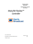
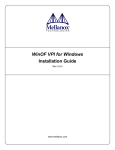
Pegasus Solo Test System
Users Manual
Document # 98-37981-00 Rev 1.0 9/21/2001
1
Table of Contents
Section
Page
Read Me First
3
Introduction
4
Installation
6
Maintenance
9
Troubleshooting
10
Appendix
11
Glossary
12
Index
13
2
Read Me First
¾ The Legal stuff
FlexStar does not assume liability for any damage incurred with the use of this product. BUYER assumes
all risk and liability for results obtained by use of Products hereunder, whether used singly or in
combination with other products.
¾ Warranty
For a period of one year, domestic and international, from the date of shipment to BUYER, SELLER
warrants the new Products to be free from defects in materials and workmanship under normal and
proper use. For a period of 90 days, domestic and international, from the date of shipment to BUYER,
SELLER warrants the Software and Firmware Products to be free from defects in materials and
workmanship in accordance with the instructions for the use of the product. For a period of one year,
domestic, and 90 days, international, (conditions apply) from the date of shipment to BUYER, SELLER
warrants the Labor of Products to be free from defects under normal and proper use. Obvious misuse
of the product or operation outside of the recommended operating conditions will void the warranty. For
further details, please refer to FlexStar’s Terms and Conditions of Sale, Item #10.
¾ Pegasus Solo Packing List
The Pegasus Solo package includes the following items:
3
•
Pegasus Solo client
•
One or more optional interface host bus adapters (installed).
•
Pegasus Solo users manual (this document).
•
Orion Host users manual
•
Fboot users manual
•
Pegasus SBC manual
•
Network Power Margin Manual
•
External drive I/O cable (installed).
•
External DC power cable (installed).
•
External Ethernet crossover cable.
•
CD containing all software required for installation on a Windows 98 or 2000 system.
•
Drive fixture (optional)
¾ Cautions and Warnings
•
Disassembly of the Solo enclosure is not recommended, except by experienced personnel only. There
is a possibility of electrical shock if the protective cover is removed.
•
Install and remove the power connector from the DUT (drive under test) only when a test has been
completed or the Solo power has been turned off.
¾ Recommended Operating Conditions
•
Temperature: 10 to 32 deg C. (operating).
•
Humidity: 10 to 85 percent RH (operating).
4
Introduction
¾ System Description
The FlexStar Pegasus Solo test system is a storage device interface test system designed to aid in the
test and debug of various types of storage devices: HDD (hard disk drive), Tape devices, CD-ROM,
DVD-ROM, etc.
The Pegasus Solo system consists of one single board computer (SBC), a power supply and network power
margining card (NPM).
The Solo client is a diskless PC containing one or more Host adapter cards. The client normally contains 32
Megabytes of system RAM and a 733 MHz CPU.
Also included in the Solo package is a 110-Watt 15V DC power supply, which supplies raw power to the
NPM for the drive under test (DUT) and power for the SBC.
The Orion server software is a Windows 98/2000 compatible application, which provides control and
data collection for all clients connected to the system. The application presents a graphical view of all
connected clients and detailed activity of a selected test node.
Device tests are performed by writing and executing test program scripts, which are edited using the
Script Editor supplied with the software.
The Orion test software is designed to be 100% compatible with the Flexstar DOS HOST software
used in earlier test products. The Orion software also adds many new features to enhance the
operation and data collection capabilities.
The Orion Host software can start, stop, pause, and resume any test. The Host software includes
power margining control and graphic performance plotting for real-time analysis of current test data
through a single stand-alone GUI. Opening, editing, and saving scripts are fast and effective through
the easy-use-use GUI environment.
¾ Product Features
The FLEXSTAR Pegasus Solo has the following features:
•
Small enclosure size lends itself to desktop and portable applications.
•
Capability to network up to 128 Solo’s together (requires extra hubs and cables).
•
The same features as the larger Flexstar rack systems.
•
Powerful Pentium Celeron processors for high performance.
•
Parametric measurement capability including data throughput and power measurements.
•
Fully programmable power for the DUT.
5
•
External video, keyboard, and mouse connectors for the client.
•
Easy upgrade to future interface adapters.
¾
Product Specifications
AC Power Input Requirement
95 VAC to 250 VAC 47-63 Hz. @ 3 amps maximum.
ESD Specification
Non-contact discharge into enclosure frame: 20 kV.
6
Installation
¾ Hardware
Refer to figure 1.0 & figure 1.1 for the following:
1) After unpacking the Solo system make sure that no damage is visible to the external chassis.
2) Connect the two Ethernet RJ-45 connectors (located on the rear panel) together using the supplied
Ethernet crossover cable to your server . If you are connecting up a hub, use the standard Ethernet
RJ-45.
3) Connect the Solo to an A.C. power source using the supplied A.C. cable. The A.C. input can range from
95 VAC to 250 VAC 47 to 63 Hz.
4) Apply power to the unit via the on/off switch located on the rear panel of the Solo. This is the main power
switch for the unit. There is also a more conveniently located power switch on the front of the unit.
Be sure to switch this on as well.
5) The Solo will boot from a Windows 98 / 2000 computer that has the Flexstar software installed and that
is configured with the Solo client MAC address.
If there are problems with the boot-up, please refer to the section on TROUBLESHOOTING. If there are
problems with software installation, please refer to the Fboot manual. Refer to the Orion Host
User’s Manual for operation instructions.
Changing Host Adapter Cards
The following sequence describes the method for removal and replacement of the interface Host adapter
cards.
1) Turn system power off and unplug the RJ-45 cable
2) Loosen the thumb screws on the front of the unit and slide out the electronics tray.
3) The host adapter bracket is attached to a right angle bracket that is part of the client SBC mounting.
Remove the screw that holds the adapter bracket in place and remove the adapter from the PCI
riser PCB.
4) Reverse this process to add a new adapter to the system.
7
Figure 1.0 Solo Rear Panel
Figure 1.1 Solo Front Panel
8
¾ Connector Assignments
DUT DC Power
Pin
Description
1
+12 Volts
2
+12 Volts
3
+12 Volt Remote Sense
4
+5 Volt Ground
5
+5 Volt Ground
6
12 Volt Ground
7
12 Volt Ground
8
+5 Volt Remote Sense
9
+5 Volts
10
+5 Volts
¾ Software
Remote Boot Software Installation
Please refer to the FlexBoot users guide and installation guide (in PDF format).
Client Software Installation
Orion client software is installed as an IMAGE file, which means that all files required for the client are
contained in a single ‘boot image’, compressed file. Client software will be released as a complete image (all
files included). The image files must be stored in the same directory as the FlexBoot remote boot manager
utility (see FlexBoot Users Guide).
NOTE: Fboot must be running before applying power to the Solo client
Orion Host Software
Refer to the Orion Host Users Guide for setup and operating instructions.
9
Maintenance
External Maintenance check (suggested every 30 days)
1) Check that the DC cooling fan located on the rear panel of the unit is functional and is moving air out
of the enclosure. Also check for obstructions and dust build-up around the fan area and around any
air inlets.
2) Check for wear on the vibration fixture located on the top cover. Check for signs of wear on the subadapter drive I/O connector. Replace sub-adapter if necessary. Note: The sub-adapter connector
may only be reliable for a limited number of insertions. The reliability depends on the connector type
and number of pins.
3) Check for wear or pin spreading on the 4 pin DC connector.
Internal Maintenance Check (suggested every 90 days)
A qualified service technician should perform the internal maintenance check, as the possibility of
electrical shock does exist.
1) Remove the A.C. cord from the receptacle at the rear of the enclosure.
2) Remove the top cover of the enclosure and check that the SBC CPU cooling fans are operating
normally. Replace the defective cooling fan if necessary.
3) Check for excessive dust build-up around the CPU and cooling fan. Clean if necessary.
4) Check to see that all PCI adapters are seated in the PCI connector.
5) Replace the top cover.
10
Troubleshooting
This section provides some troubleshooting techniques designed to aid in the debug of a non-operating
system.
No Power When AC Power is Switched ON
1) Check that both the front and rear switches are on.
2) Check the A.C. line fuse located in a protective cover just above the rear A.C. switch. This fuse, if
blown, might indicate a defective 15V power supply inside the Solo. The replacement fuse is a 3
Amp FAST BLOW type.
Client Won’t Boot from Server
1) Make sure that the FlexBoot server application has been started and the boot manager window is
present on the server screen. See the FlexBoot users guide for more details.
2) Check to see that the boot manager is using the correct client file and has the correct path name to
the file.
3) Check Windows network settings and make sure that the Netware software is running properly.
4) Check the Ethernet crossover cable. This cable connects the Client Ethernet connector to the
Server Ethernet connector located on the rear of the Solo. Replace is necessary.
11
Appendix
Technical Support
Online support and the latest releases of software are available on the Flexstar web site at
http//www.flexstar.com.
Users can also receive technical support via Email at [email protected].
12
Glossary
DUT – Device under test.
ESD – Electrostatic Discharge.
Legacy – Flexstar FS25xx test systems (replaced by Pegasus).
SBC – Single Board Computer (small form factor, highly integrated motherboard).
13
Index
A
Appendix (12)
B,C
Client Software (9)
Connector Assignments (8)
D
Description (5)
DC Power Connector (8)
E
ESD specification (6)
External Maintenance (10)
F
Features (5)
Figure 1 (8)
G
Glossary (13)
H
Hardware (7)
Host Software (9)
I
Installation (7)
14
Internal Maintenance (10)
J,K,L
Legal stuff (3)
M,N,O
P
Pegasus Solo packing list (3)
Power input requirements (6)
Q,R
Recommended Operating Conditions (4)
Remote Boot Software (9)
S
Software (9)
Software Installation (9)
Software operation (9)
Specifications (6)
T
Table of contents (2)
Technical support (12)
Troubleshooting (11)
U,V,W
Warranty (3)
Warnings (3)
15
X,Y,Z
16