1
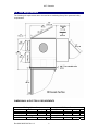
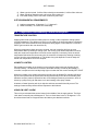
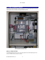
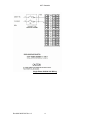
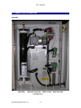
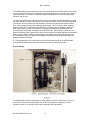
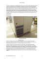
30E / Cascade 30E / Cascade Users Manual 30E Environmental Peripheral Device Test Chamber Doc # 98-36387-00 Rev 1.8 1 30E / Cascade Doc # 98-36387-00 Rev 1.8 2 30E / Cascade 1.0 Introduction ...............................................................................................4 2.0 Hardware Description...............................................................................6 2.1 Minimum Host Server PC Requirements ................................................6 2.2 Physical/Environmental Specifications ..................................................6 2.3 Site Requirements ....................................................................................8 2.4 Temperature and Humidity Control Description ....................................10 2.5 Test Electronics Description.....................................................................11 3.0 Installation .................................................................................................12 3.1 Unpacking..................................................................................................12 3.2 Connecting the Server PC........................................................................13 3.3 Power Configuration Options ..................................................................14 3.4 Connecting Power to the 30E/Cascade...................................................21 3.5 Water & Air Connections..........................................................................22 3.6 Disk Drive Connections............................................................................27 3.7 Installing the Host Software.....................................................................27 3.8 Beginning Testing.....................................................................................27 3.9 Temperature Control ................................................................................27 4.0 30E Operating Instructions ......................................................................29 4.1 Power On/Off .............................................................................................29 4.1 Beginning Testing.....................................................................................29 5.0 Safety Instructions....................................................................................30 5.1 Thermal Safety Devices............................................................................30 5.2 Electrical Safety Devices..........................................................................31 6.0 Maintenance ..............................................................................................32 6.1 Cleaning Instructions ...............................................................................32 7.0 Technical Support.....................................................................................32 Doc # 98-36387-00 Rev 1.8 3 30E / Cascade 1.0 Introduction The Flexstar 30E/Cascade test system is the industry's only Environmental Chamber designed specifically for 5.25, 3.5, 2.5, and 1.8-inch storage devices. Up to 30 devices can be tested in each 30E/Cascade, which has a temperature range of +100°C to -40°C (30E) or +100°C to -50°C (Cascade) as well as full humidity control. Flexstar test electronics and power margining synchronize full functional, parametric and voltage margining with the chamber's thermal cycling. The Flexstar 30E/Cascade is controlled by a host server PC (IBM-PC or compatible), from which the operator can write test programs, start tests, monitor tests in progress, and collect and print test results. Flexstar 30E/Cascade features include: Thermal control from +100°C to -40°C (30E) and +100° C to -50° C (30E Cascade). Relative Humidity control. Seek timing tests: 1 track, 1/3 stroke, maximum track, and average seeks. Independent 5V and 12V voltage margining with FlexStar’s voltage margin card. Voltage is programmable via the test script. Easy software upgrades via the remote boot architecture. Read/ Write testing with variable data patterns. Comprehensive parametric testing. Oven control and synchronization via the test script. Each Flexstar test port is a complete Pentium base Single Board Computer (SBC) that controls the port operation and the networking between the host server PC and the 30E/Cascade. All test results are held locally at each port and are also periodically sent to the server for backup, report, and database creation. HARDWARE FEATURES BENEFITS Inexpensive, easy to change adapters for IDE, SCSI, ATAPI, Fibre Channel, 1394, etc. Cost effective multi-interface testing, inexpensive upgrade path to future interfaces. High performance SBC provides maximum throughput capability for today’s high-speed interfaces. Fastest sustained data rate available guarantees effectiveness with current and future drives. High-speed software generated sector unique random data and data compare capability. Fastest, most reliable method of assuring data and device integrity. Diskless SBC’s boot most current software from the Server. Quick and easy upgrades and enhancements. Doc # 98-36387-00 Rev 1.8 4 30E / Cascade Voltage margining, current measurement, and power cycling. Provides essential power testing and profiling for today’s low power drives. For additional information, refer also to the Cincinnati Sub Zero Installation, Operation, and Maintenance manual. Doc # 98-36387-00 Rev 1.8 5 30E / Cascade 2.0 Hardware Description The Flexstar 30E/Cascade test system consists of a 30E/Cascade environmental system, an external Server PC, 30 sets of Flexstar test electronics, 30 Flexstar voltage-margining boards, 30 Host Bus Adapters, 30 cable-less anti-vibration fixtures, and full Client/Server software. 2.1 Minimum Host Server PC Requirements • • • • • • • IBM or compatible PC running Windows 98, Windows 2000, or Windows XP. Minimum of 256 MB RAM. Intel Celeron or Pentium P4 or better at 2.0 GHz minimum. 1.44 MB Floppy Drive. 32X or better CDRom drive. Hard drive with minimum 80 GB available. Color display. 2.2 Physical/Environmental Specifications SPECIFICATIONS Dimensions Interior Workspace (2 towers, each tower) Rear Compartment Exterior Shipping Weight Temperature Range (no load) Temperature Range (extended collar option) Temperature Uniformity (air temp measured 1” above drive surface – 0 to 30W device dissipation). Doc # 98-36387-00 Rev 1.8 30E MODEL NUMBER 30E/CASCADE 8"W x 8"D x 48"H 8"W x 8"D x 48"H (20.3 x 20.3 x 122 cm) (20.3 x 20.3 x 122 cm) 36"W x 16"D x 48"H 36"W x 16"D x 48"H (91.4 x 40.6 x 122 cm) (91.4 x 40.6 x 122 cm) 52”W x 52”D x 78”H 71"W x 51"D x 78"H (132 x 132 x 198 cm) (180 x 130 x 198 cm) (Add 7”D for extended (Add 7”D for extended collar option) collar option) 1600 Lbs. (727 Kgs) 2400 Lbs. (1090 Kgs) (Add 200 Lbs for (Add 200 Lbs for extended collar option) extended collar option) -40°C (-40°F) to -50°C (-58°F) to +100°C (+212°F) +100°C (+212°F) -25°C (-13°F) to -40°C (-40°F) to +100°C (+212°F) +100°C (+212°F) +2°C 6 30E / Cascade Temperature Resolution Relative Humidity Range Relative Humidity Control Stability Temperature Measurement Accuracy 1° C 10% to 95% RH +5 %RH +/- 0.5 deg C (Calibrated) +/- 3% RH (Calibrated) 1% +70°C to 0°C in 70 minutes 0°C to +70°C in 70 minutes 300 CFM 200-230 VAC, single 200-230 V, single or or three phase, 50/60 three phase, 50/60 Hz, Hz, 50 amps single 61 amps single phase, phase, 40 amps three 49 amps three phase phase HFC-404A HFC-404A & Dupont SUVA 95 3" diameter Watlow F4 Watlow Series 97 5 SCFM at 80 PSIG 30 30 30 3 inch Armaflex closed cell foam. Lauren Mfg. # BC-0-610 Lauren Mfg. # SS-0-1147 Humidity Measurement Accuracy Humidity Resolution Performance* Air Flow Power Requirements Refrigerant Casters Temperature Controller High/Low Limit Dry Air Purge Drive Capacity 1.8 or 2.5 inch 3.5 inch, 1 inch high 3.5 inch, 1.6 inch high Chamber Insulation Door Seal Material (Black) Door Seal Material (Gray) Silicon Rubber closed cell sponge Nosepiece Gasket Material NuSil R-1140 –85F to 465 F Silicon Adhesive *Performance will vary depending on load. Figures here represent typical cases and are for illustration purposes only. Flexstar Technology Inc. reserves the right to change, modify or revise specifications at any time without notification to user. In addition the Company is not responsible for any harm to personal damage to equipment due to improper connection or routing of electrical and plumbing. Extended Collar Option The 30E and 30E Cascade systems can be ordered with an option to extend the depth of the test cavity. This option is known as the extended collar option and adds 7” (17.8 cm) to the depth. This option is normally used to accommodate longer devices such as CD-ROM, DVD, etc. This additional length also allows a CD-ROM to open and close it’s tray without restriction. WARNING! The 30E/Cascade will cause permanent, irreversible damage to the customer’s product when tested to the extreme limits of this unit’s capability. It is up to the user to determine the maximum test parameters. See CSZ manual regarding refrigerant hazards, and laws pertaining to their handling. Doc # 98-36387-00 Rev 1.8 7 30E / Cascade 2.3 Site Requirements The following site requirements are to be used when evaluating factory floor space and utility requirements. DIMENSIONAL & ELECTRICAL REQUIREMENTS VAC 200-230 30E Single Phase Power Hz Amps 50-60 50 30E Cascade Single Phase Power VAC Hz Amps Doc # 98-36387-00 Rev 1.8 Ga 8 Ga 8 30E 3 Phase Power Hz Amps 50-60 40 Ga 8 30E Cascade 3 Phase Power VAC Hz Amps Ga VAC 200-230 30E / Cascade 200-230 H 78 in. (198 cm) 50-60 61 8 200-230 30E Dimensions W D 52 in. 52 in. (132 cm) (132 cm) 50-60 8 30E Floor Space W D 96 in. 140 in. (355.6 cm) (243.8 cm) H 96 in. (243.8 cm) 30E Cascade Dimensions W D 78 in. 71 in. 51 in. (198 cm) (180.3 cm) (129.5 cm) 49 30E Cascade Floor Space W D 96 in. 146 in. 146 in. (243.8 cm) (370.8 cm) (370.8 cm) H H NOTE: Floor space was calculated using the maximum dimensions of the unit with all doors opened plus a 12” clearance. Electrical Wiring Notes 1) Use flexible conduit. A terminal block for power connections is located in the top right section of the electrical panel. 2) A grounding terminal is provided in the right bottom of the electrical service panel. 3) Earth ground to the system must be provided. MISCELLANEOUS Heat Dissipated (in BTU) Air Heat Cooled Cycle 30240 13040 (30E) 34240 (Cascade) Compressed Air DI Water Nylon Drain PSIG SCFM MNPT PSIG Cc/min Fitting MNPT 85 - 105 5 ¼” 10 50 ¼” ½” DRY AIR PURGE 1) Air: 85 – 105 PSIG. Oil-less and waterless. Pressure is regulated internally and should be set to 60 PSIG. 2) Air inlet connection: ¼” Female NPT, use flexible tubing. 3) Flow meter setting: A = 15 SCFH, B = 125 SCFH. WATER FOR HUMIDITY SYSTEM 1) 2) 3) 4) 5) Water pressure: 10 PSIG maximum. Maximum flow rate: 100 cc/min. Water inlet connection: ¼” polypropylene compression fitting. Drain outlet connection: ½” male NPT. Drain height: Must be lower than 4”. If the customer supplied drain is higher than 4”, a pump must be installed in the drain line. It is recommended that a “P” trap be installed on the drain. Doc # 98-36387-00 Rev 1.8 9 30E / Cascade 6) Water type: de-ionized. 5 million Ohm resistivity recommended, 1 million Ohm minimum. 7) Water should be filtered through a 40-micron filter (minimum). 8) Flow meter setting: Initial = 40 cc/min continuous (not burst). SITE ENVIROMENTAL REQUIREMENTS 1) Ambient temperature: 23 degrees C +/- 5 degrees C. 2) Relative humidity: 10 to 90% non-condensing. 2.4 Temperature and Humidity Control Description TEMPERATURE CONTROL Applying either heat via resistive heating strips or cooling via the compressor cooling system controls temperature. The decision to heat or cool is made by the local temperature controller in response to the actual measured oven temperature being higher or lower than the current SET POINT (point at which the oven should be at). When the temperature climbs above the set point, the local controller will force the oven temperature down by initiating a cooling cycle. The cooling cycle duration depends on how far away the actual oven temperature is from the current set point. Conversely, when the actual temperature falls below the current set point, the controller will respond by initiating a heating cycle to force the oven temperature up. The heater duty cycle depends on how far away the actual oven temperature is from the set point. HUMIDITY CONTROL Either adding more water in the chamber or removing the water content by injecting dry air controls humidity. The decision to increase of decrease humidity is made by the Watlow F4 controller in response to the humidity being higher or lower than the current humidity SET POINT. When the humidity in the system rises above the set point, the Watlow F4 controller will cause dry air to be injected into the system thus causing the humidity to fall. When the humidity falls below the set point, water is injected into the re-circulating air stream by an atomizer, which is driven by a pump forcing air and water to mix and creating a fine spray of water. A balance of water injection and dry air injection achieves successful humidity control. The settings of water and dry airflow rate are important to this balance. HIGH/LOW LIMIT ALARM This unit is pre-wired with the sensor located in the middle of the air supply plenum. The High Limit alarm is normally set to 90 degrees C. The Low Limit Alarm is set to -45 degrees C. You should set these limits to 5 degrees above and below your absolute test limits. Doc # 98-36387-00 Rev 1.8 10 30E / Cascade ACHIEVABLE TEMPERATURE / HUMIDITY POINTS 2.5 Test Electronics Description The test electronics used for each port (also referred to as a client) is based on a small form factor Single Board Computer (SBC). The SBC is described in the associated Orion or Pegasus hardware manuals. Doc # 98-36387-00 Rev 1.8 11 30E / Cascade 3.0 Installation IMPORTANT INSTRUCTIONS -- READ BEFORE UNPACKING 3.1 Unpacking When you receive your Flexstar 30E/30E Cascade, take great care to follow these unpacking instructions otherwise damage may occur to the system. 1. 2. 3. 4. 5. 6. 7. 8. Remove the 16 bolts from the front door of the crate. Remove the front door. Remove the remaining bolts along the bottom edge of the crate. Using caution not to damage the air and water connections on top of the 30E/Cascade, slide the crate off. Cut the yellow banding holding the 30E/Cascade to the crate base. Remove the two bolts holding the retainer board at the bottom of the unit. Use forklift to raise the unit off of the base pallet, making sure that the forks are all the way under the back edges before lifting. Lifting the unit without the forks protruding all the way out the back may cause damage to the unit! (Note: It may be necessary to position the forks as far under the unit as possible and then roll the unit the rest of the way onto the forks.) Use forklift to remove 30E/Cascade from the base of the container. The shipping carton should contain the following items. Before you proceed, make sure you have everything on this list. If anything is missing, call Flexstar Customer Support at (510) 4400170. (1) (1) (1) (1) (1) (1) (1) (1) (1) 30E/Cascade Test System Optional Server PC Ethernet Cable Kit Flexstar Client software CD. 30E/Cascade/Host Software User's Manual (this document) Host Software Users Manual Flexstar FBoot Users Manual CSZ Installation/Operation Maintenance Manual Set of Temperature Controller Manuals Once the 30E/Cascade is unpacked it may be rolled to its working location, providing all surfaces it travels across are smooth, without debris, and as level as possible. The unit should have a reasonable working area to allow servicing of any of the various compartments of the unit – see site requirements. Check your facilities requirements concerning earthquake safety strap requirements. The unit should be operated within a temperature range of 23o C +/- 5o C, and no greater than 90% relative humidity non-condensing. See Site Requirements page for heat dissipated. This varies greatly depending on which option was ordered. Doc # 98-36387-00 Rev 1.8 12 30E / Cascade 3.2 Connecting the Server PC The Server PC (if supplied), is connected as follows: 1) Connect keyboard, mouse, printer, and etc. to the PC. 2) Connect a straight through Ethernet cable from the NIC card in the Server PC to the Ethernet RJ-45 jack on the rear of the 30E/Cascade chassis. Doc # 98-36387-00 Rev 1.8 13 30E / Cascade 3.3 Power Configuration Options This section provides information on power configuration. The picture below shows a view of the electrical panel, which is located on the right hand side of the unit. MAIN A.C. WIRING OPTIONS The following drawings show main A.C. input wiring options for the 30E Cascade system. See also the CSZ UBIH series maintenance manual. Doc # 98-36387-00 Rev 1.8 14 30E / Cascade Single Phase 208/220 VAC Wiring Doc # 98-36387-00 Rev 1.8 15 30E / Cascade Three Phase 208/220 VAC Wiring Doc # 98-36387-00 Rev 1.8 16 30E / Cascade Single Phase 200/230/240 VAC Wiring @200 VAC See 12V Boost Wiring @230 VAC See 12V Buck Wiring @240 VAC See 24V Buck Wiring Doc # 98-36387-00 Rev 1.8 17 30E / Cascade Three Phase 200/230/240 VAC Wiring @200 VAC See 3 PH 12V Boost Wiring @230 VAC See 3 PH 12V Buck Wiring @240 VAC See 3 PH 24V Buck Wiring Doc # 98-36387-00 Rev 1.8 18 30E / Cascade INTERNAL MOTOR POWER TRANSFORMER The following drawings shows jumper option settings for the voltage-compensating transformer that provides power to the AC motors inside the system. These motors are rated for 208 to 220 VAC and should be operated within this range. The function of the transformer is to correct the input voltage to be within the motor’s ideal operating range. Single Phase Boosting Doc # 98-36387-00 Rev 1.8 19 30E / Cascade Three Phase Boosting 110 VAC TRANSFORMER OPTIONS A step down transformer is provided to reduce the voltage from approximately 208 VAC down to approximately 115 VAC. This transformer is used to power various items (relays, controllers, etc.) that require 115 VAC and is located in the upper right corner, inside of the NEMA box. Doc # 98-36387-00 Rev 1.8 20 30E / Cascade 3.4 Connecting Power to the 30E/Cascade The electrical connection of the 30E/Cascade is to be hardwired via flexible conduit, to a fixed junction box or shutoff. A branch circuit breaker or shutoff must be located within sight of unit. The conduit should be sized to the wire gage needed for your particular configuration. The unit must be supplied with an appropriate colored ground wire and size to the ground bus bar or main terminal block depending on the configuration of your unit. Neutral connected to the ground connection with out ground is NOT acceptable. See Site Requirements page for gage of wire. The 30E/Cascade can be operated from 200VAC to 240VAC, 50 or 60Hz. Minor jumper and wiring changes are required. At the selected voltage and frequency the voltage should not vary more than +/- 6%. See the jumper and wiring configuration page for details. To meet local, federal, or international building requirements your facilities personal or qualified electrician should perform this work. Refer also to the wiring diagram provided with the Cincinnati Sub Zero manual. Doc # 98-36387-00 Rev 1.8 21 30E / Cascade 3.5 Water & Air Connections Humidity Doc # 98-36387-00 Rev 1.8 22 30E / Cascade The 30E/Cascade requires ultra-clean water in the operation of the Humidity system. An air pump is used to atomize the water as it is sprayed into the evaporator section of the unit. This is just in front of the blower. The moist air is blown throughout the chamber to raise the humidity (water content of the air) level. The water that goes into the chamber must be as pure as possible. Any dissolved salts; minerals like iron or calcium will stain the chamber. Even though you cannot see it in the water these build up over time. Not only does it stain the chamber but it will get into the HDA through the HEPA filter. Cleaning water is a little like cleaning a glass window. You cannot get it clean using dirty water or a dirty rag. To clean water various filters or processes may be needed to obtain truly clean water. Most city water is well below the cleanliness needed by the 30E/Cascade. We recommend De-ionize water be supplied to the 30E/Cascade. The Humidity section has a very good de-mineralizer filter, however even with De-ionize water the cartridge will become expended (turn orange) in about 6 months. If the cartridge turns orange in much less than 6 months you should consider having a complete water analysis and then determining what additional water treatment systems is needed. A ¼ inch polypropylene line is required from the De-ionize water supply to the 30E/Cascade. Your facilities personal should see to the installation of the de-ionize water supply. Dry Air Purge The 30E/Cascade requires compressed air in the operation of the Dry Air Purge unit. Dry air is required to accelerate dehumidifying the unit, as well as keeping the evaporator coil from becoming a block of ice during long periods of extremely cold temperatures. Doc # 98-36387-00 Rev 1.8 23 30E / Cascade It is recommended that the compressed air supply have oil and water filters located within 20 feet of the unit. A flexible hose is recommended for connection to the unit. See Site Requirements page for pressure and volume requirements. The 30E/Cascade has a built in regulator and it is factory set for 65 PSIG. The Dry Air Purge unit has two air flow meters, labeled “A” and “B” (See above). Meter A is set to a trickle flow. This is to keep the evaporator coil from icing up during long periods of cold operation. Flow meter B is set between 100 to 150 SCFM. The Humidity channel of the Watlow F4 controller uses this higher flow to dry the air in regulating the humidity. The 30E/Cascade has a very good regenerative air dryer and will provide very dry air under most conditions. If your air supply to the unit is wet after the water filter you may need a point of use desiccant dryer. Water Drain When the humidity system is lowering the humidity level or the unit is going to a cooler temperature water will condense out of the chamber. This can be a fair amount of water. The water leaves the system through a ½” male NPT pipe at the rear of the unit. There are several ways in which to handle this waste water. The water, environmentally speaking, should be quite clean. If floor drain is near by, attach a hose and run it over to the drain. If this is not possible, pipe the water out the building. Another alternative is to collect the water and use a condensate pump and pump it to a sewage pipe via a P trap. Another method of getting rid of the water is to use a condensate heater, which will evaporate the water into the atmosphere; this may not be a good idea if you are already in a high humidity environment. Under NO circumstance allow the drain water to run out onto the floor. This will create a safety hazard. Doc # 98-36387-00 Rev 1.8 24 30E / Cascade Your facilities personal will probably decide on the most expeditious method of handling the wastewater. Doc # 98-36387-00 Rev 1.8 25 30E / Cascade Chill Water The Chill Water option allows the 30E/Cascade to use cool water to remove the heat from the hot compressed gas from the compressor instead of air-cooling the gas. With this option there is much less heat dissipated into the room than with an air-cooled unit (The chill water removes the heat). The 30E/Cascade also runs much quieter. In order to utilize this feature, you must have a chill water system and plumbing to that system. If your system has a chill water-cooling option, this will have to be connected to your facilities chill water system. See the Site Requirements page for flow rates and water temperatures. The inlet and outlet are ½” male NPT. Use flexible tubing and attach it with hose clamps. Note: If the chill water system becomes clogged, it will cause a high pressure switch to trip (see figure above). This switch must be manually reset by removing the louvered panel and pressing the red button on the top of the blue body high pressure switch. Before resetting this switch, check the water lines to and from the system and clear any restrictions. Water Recirculation Option A water recirculation option can be provided for sites that do not have a water drain available. This option consists of a small sump pump, which is attached to the 30E water drain and a larger water holding tank. As water collects in the sump pump, the sump pump unit pumps the water back to the holding tank. The water in the main holding tank is then pumped to the water inlet on the humidity panel. Doc # 98-36387-00 Rev 1.8 26 30E / Cascade The sump pump is a Little Giant VCM-200LS model and it’s dimensions are 7”H x 11”W x 5”D and weighs approximately 5 Lbs (2.3 Kgs). The sump pump is normally placed on the floor just behind the drainpipe. The water holding tank is mounted below the humidity panel. Additional Information The CSZ Cincinnati Sub-Zero Manual contains additional information on Installation, Operation and Maintenance of the environmental portion of the chamber. Provided below are some additional information and tips about the chamber. Fuses and lamps are in the electrical control panel. The lamps are not consumable in nature. The fuses should only be changed by maintenance personal. Never block any vents or exhaust ports. Any blockage will cause some function of the unit to either cease operation or degrade its performance. Watlow 97 Series High/Low limit alarm This unit is pre-wired with the sensor located in the middle of the air supply plenum. The High Limit alarm is set to 85 degrees C. The Low Limit Alarm is set to -45 degrees C. You should set these limits to 5 degrees above and below your absolute test limits. 3.6 Disk Drive Connections Located at the front of the Flexstar 30E/Cascade are the power and interface connections needed for the drive or drives under test. Depending on your configuration, these connections will either be an auto-eject mechanism (standard) or a pair of cables (one for the power and one for the drive interface) for each slot. Be sure to properly orient pin 1 on the drive with pin 1 on the connector whenever connecting a drive to the tester. 3.7 Installing the Host Software See the Host Software User Manual for installation directions. 3.8 Beginning Testing You are now ready to start testing. Turn on the Flexstar 30E/Cascade with the switch located on the front panel. Next, turn on your Server PC and wait for the remote boot to load all clients with the proper client software and utility files. Please refer to your Flexstar Host Software Guide for specific instructions on the use and operation of the host software and remote booting setup. 3.9 Temperature Control Temperature / Humidity Controller The 30E environmental test sytems uses the Watlow F4 temperature/humidity controller. This unit is pre-wired and configured to communicate with the Flexstar Host software running under Windows 98, 2000, or XP. If you change any of its communications settings it will probably not communicate with the Host software. Doc # 98-36387-00 Rev 1.8 27 30E / Cascade The Flexstar test electronics is wired to be controlled by Event 5 of the temperature/humidity controller. In addition the Flexstar test electronics is wired to shut off in the event of an alarm condition. The humidity control in the 30E/Cascade chamber has certain physical limitations. The unit is not capable of obtaining a relative humidity level above 80% at temperatures above 185F/85C. On the other end of the spectrum, relative humidity levels below 8% at temperatures below 40F/4.4C are not acheivable. In addition to the physical limitations Event 2 (or humidity SW), which turns on the humidity control also indirectly, engages a solenoid, which prevents the unit from reaching the really cold temperatures. The Humidity is controlled by event 2 of the temperature/humidity controller and event 4 for the Dry Air Purge. These events are controlled by the Flexstar Host software. Refer also to the Watlow F4 temperature controller manual for additional details. Doc # 98-36387-00 Rev 1.8 28 30E / Cascade 4.0 30E Operating Instructions 4.1 Power On/Off The oven power switch is a rocker switch located on the black control panel at the front of the system on the right hand side. This switch is labeled “POWER”. This is the main power switch for all electrical functions within the oven. The switches labeled “Conditioning System”, “Humidity System”, “Dry Air Purge”, and “Power Supply” have three positions: ON, OFF, and PROGRAM. If the switches are set in the PROGRAM position, the power to these subsystems is controlled via the temperature/humidity controller. Otherwise the ON or OFF positions override the PROGRAM position. The Flexstar electronics power switch is labeled “Power Supply” on the main control panel. If the switch is placed in the PROGRAM position, power to the Flexstar electronics is controlled via event 5 of the temperature/humidity controller. 4.1 Beginning Testing You are now ready to start testing. Turn the “Unit” switch to the ON position and set the remaining switches to the PROGRAM position. Next, turn on your Server PC and wait for the remote boot to service all clients with the proper client software and utility files. Please refer to your Flexstar Host Software Guide for specific instructions on the use and operation of the host software and remote boot setup. Doc # 98-36387-00 Rev 1.8 29 30E / Cascade 5.0 Safety Instructions Listed below are other precautions that should be taken to ensure your safety as well as the proper operation of your test system. Listed below are other precautions that should be taken to ensure your safety as well as the proper operation of your test system. 1. Do not place the server on an unstable cart, stand, or table. The product may fall, causing serious injury to the operator and/or damage to the product. 2. The fan on the top of the cabinet, and slots on the sides are provided for ventilation. To ensure reliable operation of this product and to protect it from overheating, do not block or cover these openings. 3. This product should be operated with the type of power source indicated in the CSZ manual. If you are not sure of the type of power available, consult your facilities representative or local power company. 4. Never push objects of any kind into this product through the slots as they may touch dangerous voltage points or short out parts that could result in a risk of fire or electrical shock. 5. Never spill liquid of any kind on the product. 6. Do not allow anything to rest on the power cord. Do not locate the product where the power cord will be walked on. 7. Do not under any circumstances place anything in, over, or through the finger guards covering the fans installed in the product. 8. Never, under any circumstances, open the NEMA enclosure on the right side of the unit while the power to the unit is on. Extremely high voltage in the enclosure could cause injury or death. 9. Read all of these instructions and save them for later reference. 5.1 Thermal Safety Devices There are four levels of thermal safety devices that protect the unit from overheating: 1) The first level of thermal control is the Watlow F4 temperature controller, which maintains temperature by controlling the air conditioning system and heaters. 2) The second level of protection is the Watlow 97 Hi/Low Limit temperature alarm. This device will sound an alarm or remove power from the entire system if the temperature goes above or below it’s preset alarm limits. 3) The third thermal safety device is a over temperature process limit controller located in the electrical panel. This overtemp device will shut the unit off if the chamber temperature exceeds 105° C. Doc # 98-36387-00 Rev 1.8 30 30E / Cascade 4) The fourth safety level is a thermal fusable link located near the heating coils. If the air temperature near the heaters exceeds 169° C, this will also remove power to the unit. 5.2 Electrical Safety Devices All 230 VAC and 115 VAC circuits are protected with fuses and circuit breakers to meet UL standards for this type of equipment. In addition, each test port is independently fused in case of a short circuit. Doc # 98-36387-00 Rev 1.8 31 30E / Cascade 6.0 Maintenance Should a problem arise with the 30E/Cascade, please contact Flexstar technical support at (510) 440-0170 for warrantee parts or service. 6.1 Cleaning Instructions EXTERIOR Keep Cabinet free of dust and dirt. Clean the exterior of the Cabinet with a soft damp cloth. DO NOT USE ABRASIVE CLEANSER. INTERIOR NOTE: TO PREVENT ELECTRICAL SHOCK, DISCONNECT CABINET POWER BEFORE PERFORMING MAINTENANCE, SERVICE OR CLEANING. Inspect the Cabinets interior compartments frequently. If needed clean with an ESD safe cloth. By federal law, only qualified and licenced refridgeration service personel are allowed to service the refridgeration section of this equipment. 7.0 Technical Support Flexstar Technology 47323 Warm Springs Boulevard Fremont, CA 94539 (510) 440-0170 Fax (510) 440-0177 Email: [email protected] www.flexstar.com Doc # 98-36387-00 Rev 1.8 32 30E / Cascade 30E Operating Instructions ........................27 Beginning Testing .................................................................................................................................... 27 Power On/Off ........................................................................................................................................... 27 Cleaning Instructions Exterior..................................................................................................................................................... 30 Interior...................................................................................................................................................... 30 Hardware Description ..................................5 Minimum Host Server PC Requirements ................................................................................................... 5 Physical/Environmental Specifications ...................................................................................................... 5 Site Requirements....................................................................................................................................... 7 Temperature and Humidity Control Description........................................................................................ 9 Test Electronics Description..................................................................................................................... 10 Installation..................................................11 Air & Water Connections......................................................................................................................... 21 Beginning Testing .................................................................................................................................... 25 Connecting Power to the 30E/Cascade..................................................................................................... 20 Connecting the Server PC ........................................................................................................................ 12 Disk Drive Connections ........................................................................................................................... 25 Installing the Host Software ..................................................................................................................... 25 Power Configuration Options................................................................................................................... 13 Temperature Controller ............................................................................................................................ 25 Unpacking ................................................................................................................................................ 11 Introduction ..................................................3 Maintenance ..............................................30 Cleaning Instructions................................................................................................................................ 30 Power Configuration Options 110 VAC Transformer Options ................................................................................................................ 19 Internal Motor Power Transformer .................................................................................................... 13, 18 Safety Instructions .....................................28 Electrical Safety Devices.......................................................................................................................... 29 Thermal Safety Devices ........................................................................................................................... 28 Site Requirements Dry Air Purge ............................................................................................................................................. 8 Miscellaneous............................................................................................................................................. 8 Service Panel Dimensional & Electrical Requirements ............................................................................. 7 Site Environmental Requirements .............................................................................................................. 9 Water for Humidity System........................................................................................................................ 8 Technical Support......................................30 Temperature and Humidity Control Achievable Points..................................................................................................................................... 10 Humidity Control ....................................................................................................................................... 9 Temperature and Humidity Control Description High/Low Limit Alarm............................................................................................................................... 9 Temperature Control .................................................................................................................................. 9 Doc # 98-36387-00 Rev 1.8 33


![EX MV MX3 User Manual [May16].vp](http://vs1.manualzilla.com/store/data/005646159_1-0d378a1c318c2dc00419aef6af60da73-150x150.png)