1
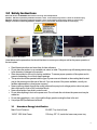
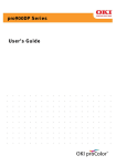
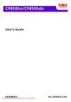
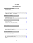
Pegasus 32B
Users Manual
32B Burn-In Peripheral Device Test Chamber
Document # 98-38088-00 Rev 1.2 05/20/2004
Table of Contents
Section
Page
1.0 Introduction
3
1.1 Hardware Description
3
1.2 Features and Benefits
4
1.3 Physical Specifications
4
1.4 Electrical Specifications
5
1.5 Temperature Control
5
1.6 System Operating Environmental Specifications
5
1.7 Storage (non operating) Specifications
5
1.8 Minimum Server Requirements
6
1.9 Site Requirements
6
2.0 Installation
7
2.1 Unpacking
7
2.2 Flexstar 32B Packing List
7
2.3 Rack Installation
7
2.4 Earth Quack Lock Down
7
2.5 Connecting the Server PC
8
2.6 Server Software Installation
8
2.6.1 Remote Boot Software Installation
8
2.6.2 Client Software Installation
8
2.6.3 Orion Host Software Installation
8
3.0 Safety Instructions
3.1 Hazardous Energy Identification
4.0 Maintenance Information
9
9
10
4.1 Single Board Computer (SBC) Description
10
4.2 NPM Power Regulator PCB Description
10
4.3 Host Bus Adapter Description
10
4.4 Maintenance Items
10
2
1.0 Introduction
The Flexstar 32B is the industry standard for low cost, high performance mass storage burn-in test
systems. The small footprint rack can hold up to 32 3.5” disk drives or similar devices while occupying less
than 5 square feet of floor space.
1.1
Hardware Description
The 32B is organized as 2 columns by 16 rows. The device environmental space is accessed via a hinged
Plexiglass door that maintains the desired temperature when closed. All test electronics and power supplies are
located behind a ‘firewall’ which isolates these components from the temperature extremes in the environmental
space.
All test electronics are accessed via a hinged rear door that allows quick access for servicing or configuration.
The power supplies are accessed via a drawer arrangement under the main system.
Each port is an individual test system with it’s own single board computer (SBC), device host adapter, and
power margining control. Each SBC is networked to the server via standard Ethernet through a multi-port hub.
Each SBC has a unique ‘MAC’ address which identifies the specific port to the server.
Each test port has it’s own power regulator for both the SBC and the device under test. The regulator
provides a fixed +5V and +12V for the SBC and a programmable +5V and +12V for the device under test.
The regulators operate from a 15V input that is bussed to all ports from a central 15V bulk power supply.
The system contains two 15V power supplies. These supplies are mounted in the drawer.
In addition, there is a 24V power supply located in the drawer used to operate the exhaust and recirculation fans. Re-circulation fans are always on whereas the exhaust fans are connected to the
temperature controller to maintain a constant temperature inside the system.
The system is heated with resistive heater strips located in the center column of the system. The system is
cooled by exhausting the hot air via fans located on the top and bottom of the system. When the exhaust
fans are on, small Mylar reed valves open at the sides of the unit to allow cool air to be pulled into the
environmental space.
3
1.2
1.3
Features and Benefits
Features
Benefits
Inexpensive, easy to change adapters
for IDE, ATAPI, SCSI, Fibre channel.
Cost effective multi-interface testing
with inexpensive upgrade path to
future interface types.
High speed Celeron based SBC with
PCI bus mastering maintains transfer
rate with all interface types.
Enough power and speed for today’s
interface’s and tomorrows
requirements.
Sector unique random data generation
with high speed data compare.
Fastest and most reliable method of
assuring data and device integrity.
Simple software upgrades can be
downloaded via the Internet.
Quick and easy upgrades and new
enhancements.
Voltage margining, current
measurement, and power cycling.
Provides essential power testing
capabilities for simple CSS tests and
advanced power measurements.
Thermal control from ambient to 55
degrees C.
Elevated temperature testing is
critical in DVT, ORT, and
manufacturing environments.
Physical Specifications (with stand)
Read and observe all WARNING labels before servicing. See example below.
Caution: Indicates a potentially hazardous situation, which, if not avoided, may result in a minor or moderate injury.
Warning: Indicates a potentially hazardous situation, which, if not avoided, could result in death or serious injury.
Danger: Indicates an imminently hazardous situation, which, if not avoided, will result in death or serous injury.
Length:
Width:
Height:
Weight:
34” (86.4 cm)
24” (61.00cm)
76” (193 cm)
575 lbs. (260.8 kg)
4
1.4
Electrical Specifications
Power Requirements: 220VAC @ 30 AMP 50/60hz Single Phase unless otherwise stated on the
machine.
Ensure customer supplied power meets this requirement. The Orion Series is high performance test
equipment. In order to ensure proper operation, care must be taken to supply computer grade AC power.
This includes a low impedance ground. Failure to do so may cause unexpected operation or other errors.
The 32B main power switch is a UL listed 1077-circuit protector. Customer supplied power must use a UL
489 or IEC 947-2 10k AIC listed breaker for proper 32B protection.
DC Bulk Power:
15V @ 200A (Internal)
DC Fan Power:
24V @ 10A (Internal)
1.5
Temperature Control
Range:
Ambient +3 deg. C to 55 Degrees C
Ramp Time:
Ambient to 55 deg C 1 Hour (Load Dependent)
Variance:
+/- 3 Degrees C
1.6
System Operating Environmental Specifications
Operating Temperature:
5 to 30 Degrees C
Relative Humidity:
10 to 80% non-condensing.
Operating Noise Level:
75 dB
1.7
Storage (non operating) Specifications
Storage Temperature:
-18 to 60 Degrees C.
Relative humidity:
5 to 90% non-condensing.
5
1.8
•
•
•
•
•
•
•
•
1.9
Minimum Server Requirements
IBM PC Compatible.
1.8 GHz Pentium processor.
256 MB ram memory.
Hard drive with at least 100 MB free disk space.
1.44 MB Floppy drive.
24x CD-ROM drive.
17 inch monitor
Windows 2000 or XP operating system.
Site Requirements
Working space in inches:
96H x 72W x 62D.
6
2.0 Installation
2.1
Unpacking
The Flexstar 32B test system is normally shipped in a wooden crate. The outer plywood container is
removed by unscrewing several bolts around the base of the outer container that secure it to the pallet.
Remove the plywood container vertically. The 32B can then be lifted off the pallet using a fork lift.
Warning: Be sure both forks are set just inside the vertical uprights of the stand.
2.2
Flexstar 32B Packing List
The Flexstar 32B system should include the following items:
(1)
(1)
(1)
(1)
(2)
(1)
(1)
(1)
(1)
(1)
(1)
(1)
Flexstar 32B Users Manual (this document).
Removal Tool Assembly P/N 01-34046-00
PWA, Ethernet Adapter NIC Card P/N 02-38027-00
Cable, ESD Wrist Strap P/N 03-34299-00
Cable, RJ45-RJ45, 187” P/N 03-38532-187P
Cable, Video / Keyboard adapt. P/N 03-37141-68
Chamber Information Floppy Disk P/N 88-35806-00
Orion Host software CD P/N 87-37601-00
Orion Host User Manual P/N 98-36391-00
Flexstar F-Boot Manual P/N 98-35783-00
Pegasus SBC user’s manual P/N 98-37844-00
NPM 1-Ch power card manual P/N 98-37821-00
2.3 Rack Installation
Roll the rack into the desired location. NOTE: 36” of working space should be provided on all sides
with electrical enclosures and cooling fans. Using an adjustable wrench, tighten the four load locks
against the floor. Warning: the load locks are intended to hold the cabinet in position and are NOT
intended to support the weight of the cabinet.
2.4 Earthquacke Lock Down
To install the 104B in an Earthquake prone region complete Section 2.3 Rack Installation and the
following instructions. To secure the rack to the ceiling use strut channels bolted to the ceiling and the
sides of the rack 6” in from the rear and 6” from the top. Use a ¼” or 5/16” nut and bolt. To secure
the rack to the floor use a strut channel bolted floor and a U bolt bolted to the channel around one of
the horizontal cross members of the racks base. Hardware and mounting components not
included.
7
2.5
Connecting the Server PC
The Server has two Ethernet cards installed. One card is for the FlexStar clients, the other is for site LAN.
2.6
Server Software Installation
Server software consists of the following installations:
2.6.1 Remote Boot Software Installation
Each test port in the 32B is a small Celeron based single board computer (SBC) and operates a single
device under test (DUT). Each test port is also diskless which means that the operating system and test
software must be remotely loaded from the server PC. This is accomplished with a special BIOS which
has a remote bootstrap loader built in. The bootstrap loader connects to the server PC whenever the test
port is reset or powered up. The OS and test software is then loaded into a RAM disk and executed from
there. The size of the RAM disk is at least 6 MB depending on the specific interface being tested and the
buffer size requirements.
Specific installation instructions can be found in the Flexstar Remote Boot Installation Manual.
2.6.2 Client Software Installation
Client software is remote booted from the server when the client is powered on or reset. Client
files are stored on the server in a specific folder, which is designated for use during remote
boot. Copying the newer files into this folder and re-booting the clients upgrades the software.
The new file name must be selected in the FBoot GUI. For more details, see the FBoot user’s
manual.
2.6.3 Orion Host Software Installation
Orion Host software is contained on a single CD. The software is loaded by running SETUP.EXE on the
Server and following the on-screen installation directions.
The installer will select ‘C:\PROGRAM FILES\FLEXSTAR\ORION’ as the default directory. It is
recommended that you install into this directory.
When upgrading to a newer version of Host, it is also recommended that you perform a full install since
other library files may also have changed. Performing a full install will guarantee that all older files will be
overwritten. See Orion Host Software User’s Manual for further information.
8
3.0 Safety Instructions
Read and observe all WARNING labels before servicing. See example below.
Caution: Indicates a potentially hazardous situation, which, if not avoided, may result in a minor or moderate injury.
Warning: Indicates a potentially hazardous situation, which, if not avoided, could result in death or serious injury.
Danger: Indicates an imminently hazardous situation, which, if not avoided, will result in death or serous injury.
MAIN POWER BREAKER
HEATER BAY
MAIN POWER INLET
Listed below are the precautions that should be taken to ensure your safety as well as the proper operation of
the test system.
•
•
•
•
•
•
•
•
•
Read these instructions and save them for later reference.
Do not place the product on an unstable cart, stand, or table. The product may fall causing serious injury
to the operator or damage to the product.
Slots are provided on the unit for cooling ventilation. To ensure proper operation of the system and to
prevent overheating, do not block these openings.
This product should be operated with the type of power source indicated on the marking label located
next to the power input at the rear of the unit. If you are unsure of the power available, consult your
facilities representative or local power company.
Never push any objects through the cooling vents as they may touch voltage points or short out parts
that could result in a risk of fire or electrical shock.
Never allow liquids of any kind to enter the unit.
Do not allow anything to rest on the power cord. Do not locate the unit where the power cord may be
walked on.
Do not place anything in, over, or through the finger guards covering the fans in the unit.
Use proper ESD procedures at all times.
3.1 Hazardous Energy Identification
Main Circuit Protector:
25 AMP, Top front left side.
15VDC 1500 Watt Power
100 Amp, QTY 2, Inside the lower rear power tray.
9
24VDC 250 Watt Power Supply
10.4 AMP, QTY 2, Inside the lower rear power tray.
15VDC Buss Bar
100 Amp, Qty 1, Inside Panduit wire chase inside SBC
bay.
3.75 Amp, QTY 2, Inside DUT bay behind the circulation
fans.
750 Watt Finned Strip Heater
10
4.0 Maintenance Information
This section discusses various details about the test electronics and connector pinouts.
4.1
Single Board Computer (SBC) Description
The test system is based around a small form factor Pegasus SBC. This SBC offers high performance, a full
range of features, and low cost. For detailed information about the Pegasus SBC, please see the Pegasus
SBC manual (part # 98-37844-00).
4.2
NPM Power Regulator PCB Description
A special Network Power Margin (NPM) regulator card provides system and DUT power. For detailed
information about the NPM regulator card, please refer to the NPM manual (part # 98-37821-00 for 1 channel or
part # 98-37591-00 for 4 channel).
4.3 Host Bus Adapter Description
The specific device interface is determined by the type of Host Bus Adapter (HBA) that is installed into the PCI
slot of the SBC. The types of interfaces supported are:
•
•
•
•
•
•
•
IDE – UDMA-100 & UDMA 133.
ATAPI (CDROM, DVD, CDRW).
SCSI – up to 320 MB/S.
Fibre Channel – 2 GB/S.
PCMCIA.
SATA 1.0
SATA 2.0 (beginning July 1 2004)
4.4 Maintenance Items
Every six months the following procedures are recommended:
1) Turn off system
2) Vacuum out any dust or debris that has collected. Clean soiled surfaces with a mild cleaner.
3) Turn on system and check:
a) All fans for proper operation.
b) Flaps seal properly in recirculation mode.
c) 15 volt supplies are working properly.
d) 24 volt supply is working properly.
e) Heaters and temperature controller are working properly.
11