1
R8C/3NT Group
17.7
17. Timer RA
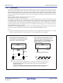
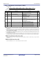
Pulse Period Measurement Mode
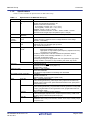
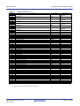
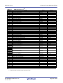
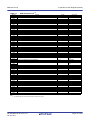
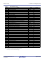
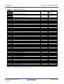
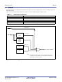
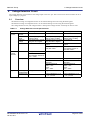
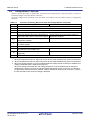
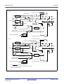
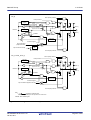
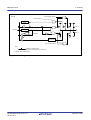
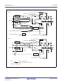
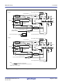
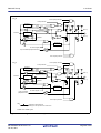
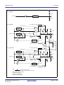
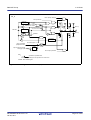
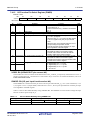
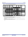
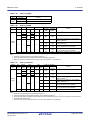
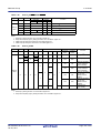
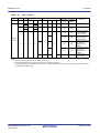
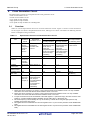
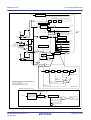
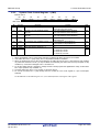
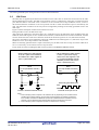
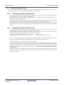
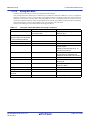
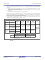
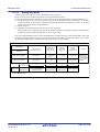
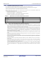
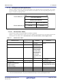
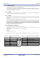
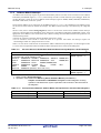
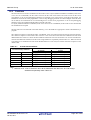
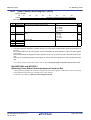
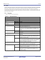
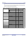
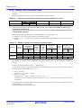
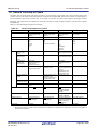
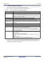
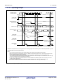
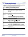
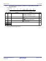
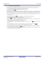
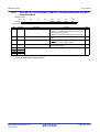
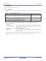
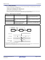
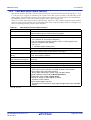
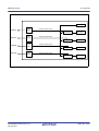
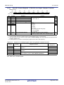
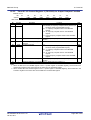
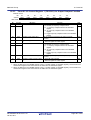
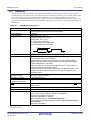
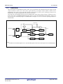
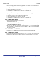
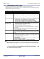
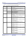
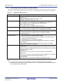
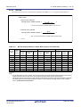
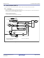
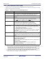
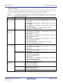
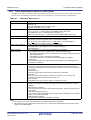
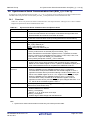
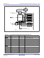
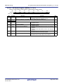
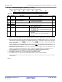
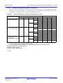
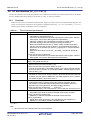
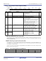
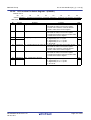
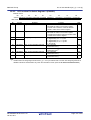
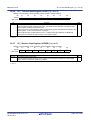
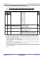
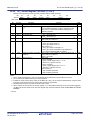
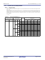
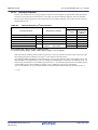
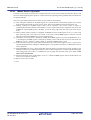
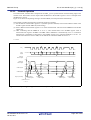
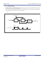
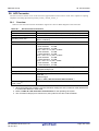
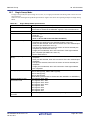
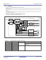
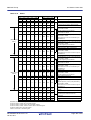
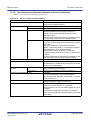
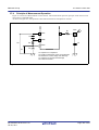
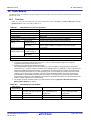
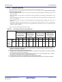
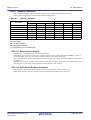
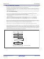
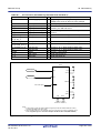
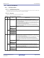
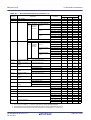
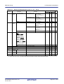
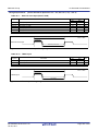
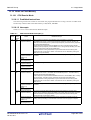
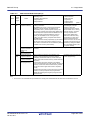
In pulse period measurement mode, the pulse period of an external signal input to the TRAIO pin is measured
(refer to Table 17.6 Pulse Period Measurement Mode Specifications).
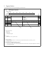
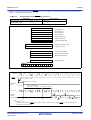
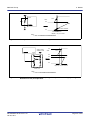
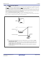
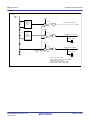
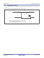
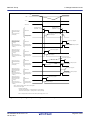
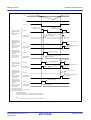
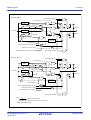
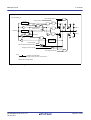
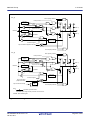
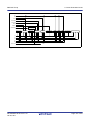
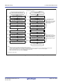
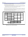
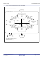
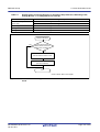
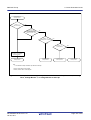
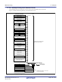
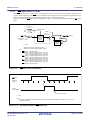
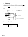
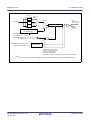
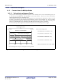
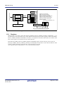
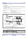
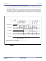
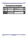
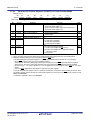
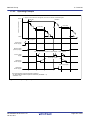
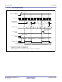
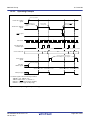
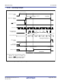
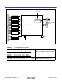
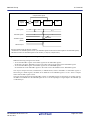
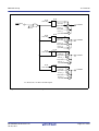
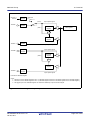
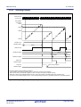
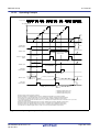
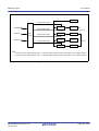
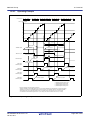
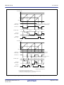
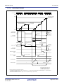
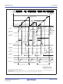
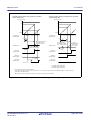
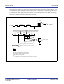
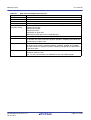
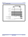
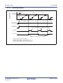
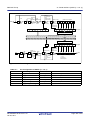
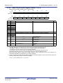
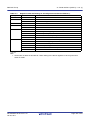
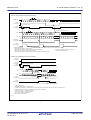
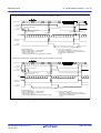
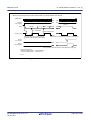
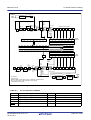
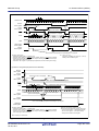
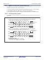
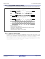
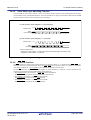
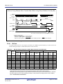
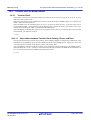
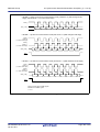
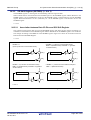
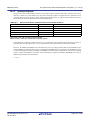
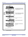
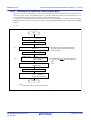
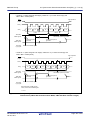
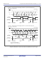
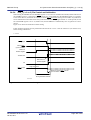
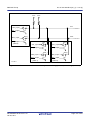
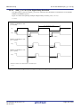
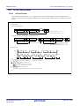
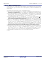
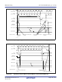
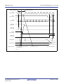
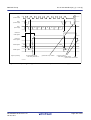
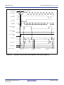
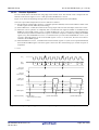
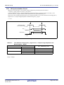
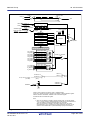
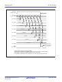
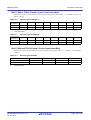
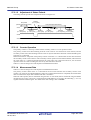
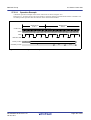
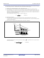
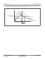
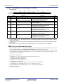
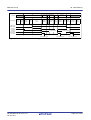
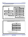
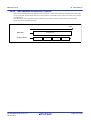
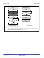
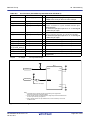
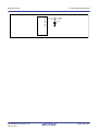
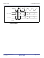
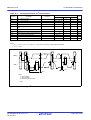
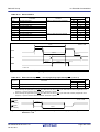
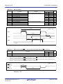
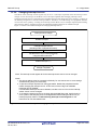
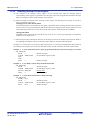
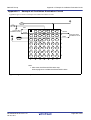
Figure 17.4 shows an Operating Example of Pulse Period Measurement Mode.
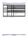
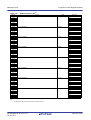
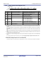
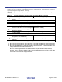
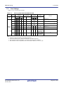
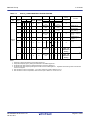
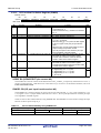
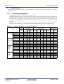
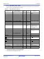
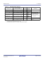
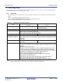
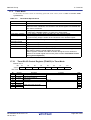
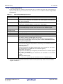
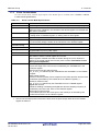
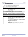
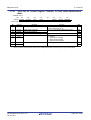
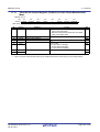
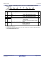
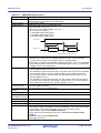
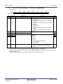
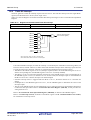
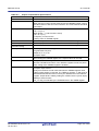
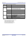
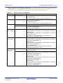
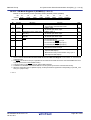
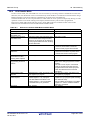
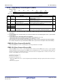
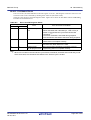
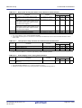
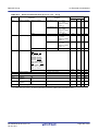
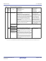
Table 17.6
Pulse Period Measurement Mode Specifications
Item
Count sources
Count operations
Specification
f1, f2, f8, fOCO, fC32, fC
• Decrement
• After the active edge of the measured pulse is input, the contents of the read-out
buffer are retained at the first underflow of timer RA prescaler. Then timer RA
reloads the contents in the reload register at the second underflow of timer RA
prescaler and continues counting.
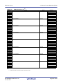
Count start condition 1 (count starts) is written to the TSTART bit in the TRACR register.
Count stop conditions • 0 (count stops) is written to TSTART bit in the TRACR register.
• 1 (count forcibly stops) is written to the TSTOP bit in the TRACR register.
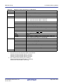
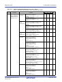
Interrupt request
• When timer RA underflows or reloads [timer RA interrupt].
generation timing
• Rising or falling of the TRAIO input (end of measurement period) [timer RA
interrupt]
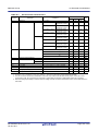
TRAIO pin function
Measured pulse input (1)
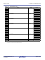
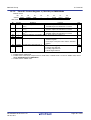
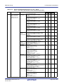
TRAO pin function
Read from timer
Write to timer
Selectable functions
Programmable I/O port
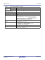
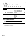
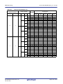
The count value can be read by reading registers TRA and TRAPRE.
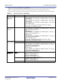
• When registers TRAPRE and TRA are written while the count is stopped, values
are written to both the reload register and counter.
• When registers TRAPRE and TRA are written during the count, values are
written to the reload register and counter (refer to 17.3.2 Timer Write Control
during Count Operation).
• Measurement period selection
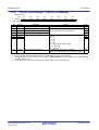
The measurement period of the input pulse is selected by the TEDGSEL in the
TRAIOC register.
• Measured pulse input pin select function
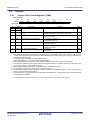
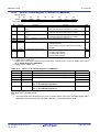
P1_5, P1_7 is selected by bits TRAIOSEL0 and TRAIOSEL1 in the TRASR
register.
• Digital filter function
Whether enabling or disabling the digital filter and the sampling frequency is
selected by bits TIPF0 and TIPF1 in the TRAIOC register.
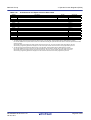
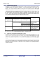
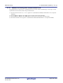
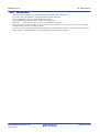
Note:
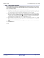
1. Input a pulse with a period longer than twice the timer RA prescaler period. Input a pulse with a
longer “H” and “L” width than the timer RA prescaler period. If a pulse with a shorter period is input
to the TRAIO pin, the input may be ignored.
R01UH0087EJ0100 Rev.1.00
Jan 25, 2011
Page 235 of 601