1
R8C/3NT Group
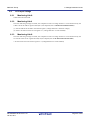
27.5
27. Sensor Control Unit
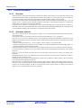
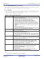
Notes on Sensor Control Unit
27.5.1
A/D Converter
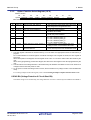
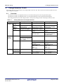
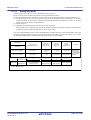
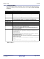
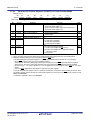
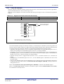
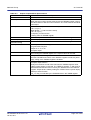
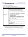
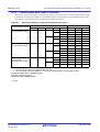
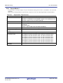
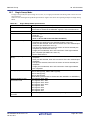
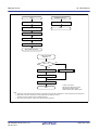
Do not use the A/D converter (or do not set the ADST bit in the ADCON0 register to 1) while the sensor control
unit is operating.
27.5.2
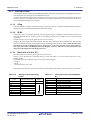
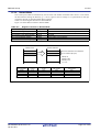
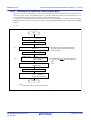
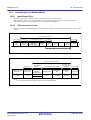
Address to Store Detection Data
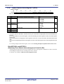
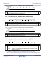
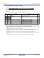
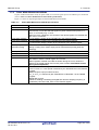
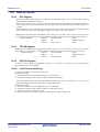
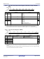
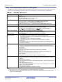
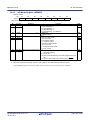
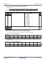
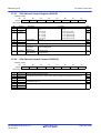
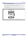
Set the start address in the SCUDAR register.
Also set the same start address in the DTDARj (j = 0 to 23) register of the DTC.
For the DTC settings, refer to 15. DTC.
27.5.3
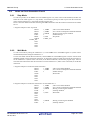
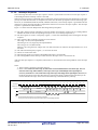
Wait Mode
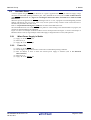
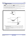
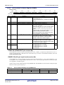
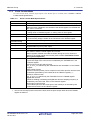
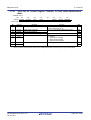
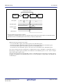
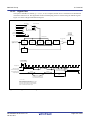
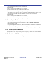
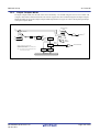
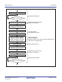
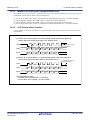
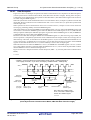
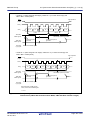
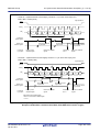
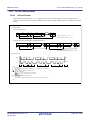
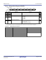
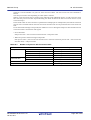
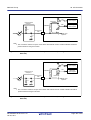
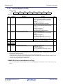
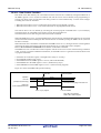
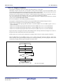
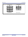
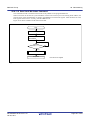
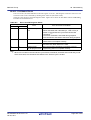
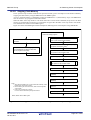
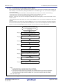
• When the sensor control unit is used in wait mode, set wait mode immediately after setting the SCSTRT bit in
the SCUCR0 register to 1 (measurement starts).
If the MCU exits wait mode during touch detection, the EWMER bit in the SCUFR register is set to 1. The
detection data at that time is undefined.
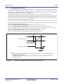
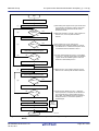
• To enter wait mode while the sensor control unit is operating (the SCUE bit in the SCUCR0 register is set to
1), do not use the CM30 bit (wait control bit) in the CM3 register. Use the WAIT instruction.
• When the sensor control unit is used in wait mode, set the WTFMACT bit in the FMR1 register to 1 (flash
memory operates in wait mode).
27.5.4
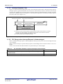
Measurement Trigger
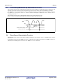
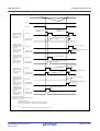
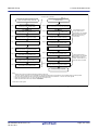
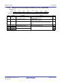
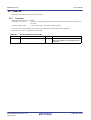
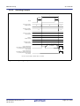
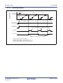
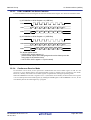
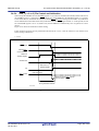
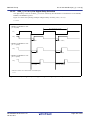
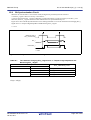
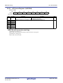
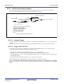
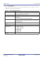
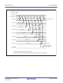
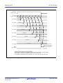
If a measurement start trigger is generated during forced stop, all counter values change to 0.
27.5.5
Charging Time
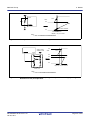
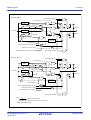
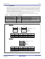
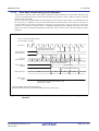
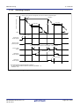
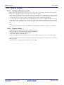
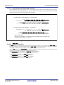
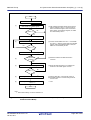
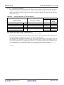
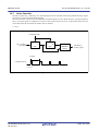
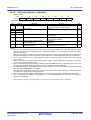
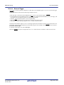
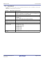
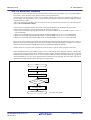
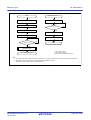
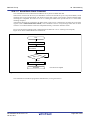
To prevent measurement data from being overwritten to the next measurement data, the sensor control unit
should be kept charged until DTC transfer or internal SDMA transfer is completed.
R01UH0087EJ0100 Rev.1.00
Jan 25, 2011
Page 498 of 601