1
Applicable Country & Regions:
All Regions
Product Service Manual – Level 2
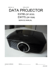
Service Manual for BenQ:
Projector/SX930
<9H.JEG77.15X>
Version: 00a
Date:2015/09/22
Notice:
For RO to input specific “Legal Requirement” in specific NS regarding to responsibility and liability
statements.
Please check BenQ’s eSupport web site, http://esupport.benq.com, to ensure that you have
the most recent version of this manual.
First Edition (Sep., 2015)
© Copyright BenQ Corporation 2015 All Right Reserved.
1
Content Index
1. Abbreviations & Acronyms ............................................................. 4
2. About This Manual............................................................................ 5
2.1 Trademark .................................................................................................................... 5
2.2 Introduction................................................................................................................. 5
2.3 Important Service Information ..................................................................................... 5
2.4 Safety Notice ............................................................................................................... 6
2.5 Compliance Statement ................................................................................................. 6
2.6 General Descriptions ................................................................................................... 6
2.7 Related Service Information ......................................................................................... 6
3. Product Overview ............................................................................ 7
3.1 Specification Overview ................................................................................................ 8
3.2 Packing ....................................................................................................................... 28
3.3 Customer Acceptance................................................................................................ 35
4. Level 1 Cosmetic / Appearance / Alignment Service .............. 38
4.1 Cosmetic / Appearance Inspection Criteria................................................................ 38
4.2 OPERATIONAL INSPECTION CRITERIA ................................................................. 41
4.3 Software/Firmware Upgrade Process ......................................................................... 47
4.4 Factory Menu............................................................................................................. 71
4.5 RS-232 connection..................................................................................................... 76
4.6 Adjustment / Alignment Procedure............................................................................. 80
5. Level 2 Circuit Board and Standard Parts Replacement ....... 84
5.1 Product Exploded View .............................................................................................. 84
Module 2 – ASSY UPPER CASE ....................................................................................... 86
5.2 Product Disassembly / Assembly ................................................................................ 88
5.3 Module Assembly Key Point - Optical Engine ........................................................... 103
5.4 Module Assembly Key Point - Mechanical ................................................................. 117
5.5 Block Diagram ......................................................................................................... 133
5.6 Trouble shooting ...................................................................................................... 134
Appendix 2 - Code List: IR / RS232 / DDC Data ........................ 147
Appendix 3 – Ceiling Mount Drawing.......................................... 156
Appendix 4 - Optical Measurement............................................. 157
Appendix 6 - Design Verification Test Procedure ...................... 168
Appendix 7 - Thermal and Noise Test Procedure...................... 171
2
Update History
Revision
Rev. 00a
Chapter
Changes
Initial version
Date
2015/9/21
3
1. Abbreviations & Acronyms
A
A/D
Analog to Digital
B
BenQ
BenQ Corporation
C
C/W
Color Wheel
CM
Concave Mirror
D
DLP
Digital Light Processing / Texas Instruments®
DMD
Digital Micro mirror Device
DVI
Digital Video Interface
DVI-I
Digital Video Interface-Integrated
P
PL
Projection Lens
POM
Pond of Mirrors
R
RS232
Interface Between Data terminal Equipment and
Data Communications Equipment Employing
Serial Binary Data Interchange
S
SVGA
SXGA
Super Video Graphics Array, A screen resolution
of 800 x 600 pixels.
Super XGA. A screen resolution of 1280x1024
pixels.
V
VGA
Video Graphics Array. A screen resolution of
640x480 pixels.
X
XGA
A screen resolution of 1024x768 pixels.
4
2. About This Manual
This manual contains information about maintenance and service of BenQ products. Use this manual
to perform diagnostics tests, troubleshoot problems, and align the BenQ product.
Important
Only trained service personnel who are familiar with this BenQ Product shall perform service
or maintenance to it. Before performing any maintenance or service, the engineer MUST
read the “Important Safety Information”
2.1 Trademark
The following terms are trademarks of BenQ Corporation:
BenQ
Other companies, products, or service names may be the trademarks of their respective companies.
2.2 Introduction
This section contains general service information, please read through carefully. It should be stored
for easy access place.
2.3 Important Service Information
RoHS (2002/95/EC) Requirements – Applied to all countries require RoHS.
The RoHS (Restriction of Hazardous Substance in Electrical and Electronic Equipment Directive) is a
legal requirement by EU (European Union) for the global electronics industry which sold in EU and
some counties also require this requirement. Any electrical and electronics products launched in
the market after June 2006 should meet this RoHS requirements. Products launched in the market
before June 2006 are not required to compliant with RoHS parts. If the original parts are not RoHS
complaints, the replacement parts can be non ROHS complaints, but if the original parts are RoHS
compliant, the replacement parts MUST be RoHS complaints.
If the product service or maintenance require replacing any parts, please confirming the RoHS
requirement before replace them.
5
2.4 Safety Notice
1
2
3
4
5
6
7
8
9
Make sure your working environment is dry and clean, and meets all government safety
requirements.
Ensure that other persons are safe while you are servicing the product.
DO NOT perform any action that may cause a hazard to the customer or make the product
unsafe.
Use proper safety devices to ensure your personal safety.
Always use approved tools and test equipment for servicing.
Never assume the product’s power is disconnected from the mains power supply. Check that it
is disconnected before opening the product’s cabinet.
Modules containing electrical components are sensitive to electrostatic discharge (ESD). Follow
ESD safety procedures while handling these parts.
Some products contain more than one battery. Do not disassemble any battery, or expose it to
high temperatures such as throwing into fire or it may explode.
Refer to government requirements for battery recycling or disposal.
2.5 Compliance Statement
Caution: This Optical Storage Product contains a Laser device. Refer to the product specifications
and your local Laser Safety Compliance Requirements.
2.6 General Descriptions
This Service Manual contains general information. There are 2 levels of service:
Level 1: Cosmetic / Appearance / Alignment Service
Level 2: Circuit Board or Standard Parts Replacement
2.7 Related Service Information
Service Web Site
eSupport Website:
BenQer: http://esupport.benq.com/v2
ASP: http://esupport.benq.com/
6
3. Product Overview
The projector consists of DLP projector controller, Lamp controller, Power supply system, and
System cooling controller. The DLP controller captures digital PC data and video data and then
converts them into the DMD display device. The Lamp controller dominates the lamp’s power and
synchronizes its frequency with color display sequence. The Power supply unit controls the AC line
power factor and converts primary voltage to secondary low voltages for digital board. The System
cooling controller drives the airflow to quench the lamp’s heat and electrical component’s heat.
Specification Overview
Panel Information
Projection Lens Specification
Optical Specification
Lamp Specification
Mechanical Specification
Packaging
Thermal Specification
Power Requirements
Compatibility
User Interface
Regulatory
Reliability
Other Feature
Input / Output Connectors
Input Terminals
Output Terminals
Control Terminals and Interface
Accessories
Environmental
Electrical Specification
Power Supply Specification
UI Specification
7
3.1 Specification Overview
Specification Overview
SX930
Item
1.Panel / Driver IC Information
1.1 Panel Type
1.2 Package Type
1.3 Size
1.4 Pixels
1.5 Color Depth
1.6 Driver Type
1.7 Panel Pixel Quality
1.8 Image Imperfection
Version: 02
Specification
0.7"XGA 2xLVDS 14° Type DMD
Type A
0.7”
1024(H) x 768(V)
30 Bits (1.07 Billion Colors)
DDP 4421-HV
Follow TI spec. (Refer to Appendix 4 )
Follow TI spec. (Refer to Appendix 4 )
Display : NA
1.9 LAN Drive Type
Control : A-top
2. Projection Lens Geometry Specification
Note: Projection Size for measurement as below: with mark ”*”
1. DMD Aspect ratio(16:9) ->projection size: 95 inch( diagonal) image size
2. DMD Aspect ratio(16:10) ->projection size: 87 inch( diagonal) image size
3. DMD Aspect ratio(4:3) >projection size: 78 inch diagonal) image size
Wide
Tele
2.1 F/#
2.1
2.63
Wide:
Tele:
2.2 Focal Length
21.7 mm
34.64 mm
2.3 Zoom Ratio
1.6 ±2%
2.4 Throw Ratio
1.5~2.4 (Wide 78” ±3% @ 2.38m)
2.5 True Zoom
NA
2.6 H,V Offset*
2.6.1 Offset H(%)*
0% ± 2.5% Appendix A.15)
2.6.2 Offset V(%)*
default 107.5% ± 2.5% (Mode B, Appendix A.15)
Vertical shift: +5%@ at default 107.5%±2.5%
2.6.3 Lens Shift(%)*
"+": lens shift upward
"-": lens shift downward
2.7 Focus Range (m)
W: 1.86 ~ 9.32m T: 2.98 ~ 14.91 m
2.7.1 Screen Size (inch)
60” ~ 300” (Check by E pattern, Appendix Pattern 6)
2.8 TV Distortion
Wide & Tele <1%
2.9 Keystone Distortion
Wide & Tele <1%
2.10 Screen Distortion*
|A,B| <=5mm, |C|<=5.0 mm @ 78" at 107.5% V offset
2.11 Focus Quality*
(1) The pattern can be uniformly focused – then pass!
(2) If it’s difficult to judge, then check 2.11.2
2.11.1 区 Pattern*
Defocus/Flare judge criteria refer to Appendix A16/17
2.11.2
R
G
B
Defocus (Maximum) *
2.5
2.5
2.5
Flare (Maximum) *
3.5
3.5
3.5
Center Zone
All other area
2.12 Lateral Color*
R-G
<2/3 pixel
<1.0 pixel
8
2.13 DOF (Min. cm)
2.14 Zoom Ring Torque
2.15 Focus Ring Torque
2.16 Lens offset Position
2.17 Zoom&Focus shaking level
2.18 Lens Shift Shaking(lock) Level
2.19 Lens Shift Speed(sec)
(only for motorized len shift)
3.Optical Specification
B-G
<2/3 pixel
<1.0 pixel
R-B
<1.0 pixel
<1.0 pixel
DOF 5 cm checked by E pattern. Refer to Appendix A24
"+" and"-" desinition
"+":move projector backward to far away the screen and until
focus limit. Record the backward distance(+) for the rear
depth of focus.(後景深)
"-":move projector forward to close to the screen and until
focus limit. Record the backward distance(-) for the front
depth of focus.(後景深)
200~650g follow Qisda Lens spec
50~300g follow Qisda Lens spec
115%出貨(SI Provide) *For Lens Shift Models.
Follow limit sample (When needed)
Lock level:5 Lens weight
N.A.
Test under “ * ” (diagonal) image size with Wide projection lens position.(base on lens best design value)
Reference Meter: CL-200 Meter (SN head:81531011, body:82521013)
3.1 ANSI Brightness
3.2 ANSI (-) uniformity
3.3 ISO Uniformity
3.4 ANSI Contrast
3.5 FOFO Contrast
3.6FOFO Contrast with DB
3.7 color wheel segment
3.8 color wheel speed
3.9 Color Coordinate
(Confirm at PVT stage)
3.10 Color Uniformity
(Confirm at PVT stage)
3.11 Color Gamut(Compare to NTSC)
3.12 Light Leakage in AA
Normal: Minimum 6300 lm (environment>35℃ , MKT>6000
lm )
Normal: Typ 6650 lm (For reference)
ECO: Typ 5320 lm (For reference)
Connect HDMI =Optical native(DMD-full-on)
If no HDMI Source, measure PC Input ≧ 97% of Optical
Native (DMD-full-on)
Minimum -50%
Minimum 65%
Minimum 150:1
Minimum 1500:1 (WCE2), Refer to appendix4-A23
N.A.
70Y30W90C30B65G75
Data model:50Hz 2X 60Hz 2X
Color
x
y
Δ(u’,v’)
White
0.319±0.02
0.353±0.02
±0.03
Red
0.637±0.04
0.357±0.04
±0.04
Green
0.339±0.04
0.570±0.04
±0.04
Blue
0.147±0.03
0.068±0.03
±0.04
Color
△uv
White
≦0.02
Red
≦0.03
Green
≦0.02
Blue
≦0.02
Data model: Typical 60%
△≦0.5 lux compared with center point @ full black pattern
within 60”.
This light-leakage is only described as the spot light with
obvious shape. The uniformity difference of black pattern is
9
3.13 Light Leakage out of AA
3.14 Ghost
3.15 Defect (Color Band, Dark Corner,
Dark band)
3.16 Preset mode setting
4.Lamp Specification
4.1 Lamp
4.2 Lamp Sync Type
4.3 Lamp Flick
4.4 Lamp Power
5. Mechanical Specification
5.1 Color & Texture specifications
5.2 Physical Dimensions(Width X
Depth X Height)
5.3 Net Weight
5.4 Security Slot
5.5 Lens Cover
5.6 Adjustment Feet
not included. (Except DMD Defect)
≦1 lux, @ full black pattern with 60”~80“
≦3 lux, @ out of full black pattern with diagonal 80~120”
≦20 lux, @ out of full black pattern with diagonal >120”
(Except DMD Defect and high zoom ex: D zoom /zoom5 /
B zoom )
Ghost (Confirm at EVT2 stage)
Follow limited sample (When needed).
USHIO NSH465W E22.7
AC Lamp
Follow limited sample (When needed).
Normal Mode
440W -> 425W
ECO Mode
360W
Image-care or equivalent
NA
Refer to ID document for details
446*336*152(mm)
≦8.5kg
Kensington compatible slot 20Kg break away force
Detached lens cover
Adjustable foot in front, rubber foot in rear.
Front/ Rear foot
Tilt: 0-4.5∘,
Right/Left: +4.0∘/-4.0∘
5.7 Ceiling Mounting
5.8 Screws
Match BenQ’s ceiling mount required.
Use the same mounting as current shipping projectors.
All color of screws should similar with the plastic color which
close it.
5.9 During PVT stage, limited sample
of color and texture should be
approved by BenQ industrial
N/A
designer and mechanical
engineer.
5.10 Packaging
EPE
Cushion Material
6. Thermal Specification
Mechanical component temperature at ambience 0~40℃
Normal surface:
6.1 Surface held or touched for short Metal< 60 ℃ Plastic< 85 ℃
periods
Bottom surface @25℃
Metal< 55 ℃ Plastic< 70 ℃
Metal
Plastic
6.2 Surface which my be touched
< 70 ℃
< 95 ℃
6.3 Exhaust Air
< 95 ℃
Normal mode: 39dBA @ 25°C(table center)
6.4 Audible Noise Level
Typical
Eco mode: 36dBA @ 25°C(table center)
10
Normal mode : 41dBA @ 25°C(table center)
Eco mode : 38dBA @ 25°C(table center)
Max.
6.5 Fan Numbers
7
6.6 Sound Quality
1K~20K < 9dB (follow ECMA-74)
6.7 Auto Blank distance
7.0 Power Requirements
7.1 Power Supply (Normal)
NA
Max.
Standby
7.2 Power consumption
7.3 Power Connector
7.4 Power Switch
8.0 Compatibility
8.1 Data Compatibility (Version 03)
8.1.1 RGB Digital
8.1.2 RGB Analog
8.1.3 Macintosh
8.2 Video Compatibility
8.2.1 SDTV
8.2.2 EDTV
8.2.3 HDTV
8.2.4 Video
8.3 Frequency
8.3.1 H-Sync
8.3.2 V-Sync
8.4 DDC
9.0 User Interface
9.1 Operator Keypad
9.2 LED Indicators
9.2.1 Power On/Off Status
9.2.2 Lamp Status
9.2.3 Temperature Status
9.3 Electric Keystone
9.4 Remote Control
10.0 Regulatory
10.1 Safety
10.2 EMC
10.3 ESD
Normal
ECO
ECO Blank
IEC 60320 C14
No
645W
0.5W Max. at 100 ~ 240VAC
(disable loop through, Lan function)
3W MAX at 230VAC 50HZ for network
mode
Typical 610W @110Vac
Typical 564W@110Vac
Same as Eco Mode
Refer to 2.1.4 HDMI/DVI Input
Refer to 2.1.5 PC Input
MAC 13/16/19/21
480i/576i
480P/576P
720@50P/60P,1080@50i/60i/24p/25p/30p/50p/60p
NTSC/ NTSC4.43/ PAL (Including PAL-M, PAL-N)/ SECAM/
PAL60/
15~102KHz
23 ~ 120 Hz
EDID 1.3
10 Keys ( Same as SU922 )
Power ; Source ;Auto ; Blank ; Mode/Enter ; Menu/Exit ;
Right (Keystone ) ; Left (Keystone ) ; Up(Keystone+) ;
Down(Keystone-)
3 LEDS
Refer to 4.4 LED definition
Refer to 4.4 LED definition
Refer to 4.4 LED definition
Horizontal keystone and adjustable range 30
Vertical keystone and adjustable range 30
5F.261W9.211 (WW SKU) / 5F.261W9.151 (J SKU)
Vendor : Refer to RFQ
Internal : Refer to B106 document
Vendor : Refer to RFQ
Internal : Refer to B106 document
Follow IEC 61000-4-2 and EN55024 regulation
11
10.4 GP
1) BenQ Restriction of Hazardous Substance Guideline
(SUP-QM-07-02)
2) Other GP control items please refer PRR
11.0 Reliability
40000 hours except DMD chip, Color wheel, Lamp and Fan,
Ballast
1). Lamp hour = Total lamp hour= X(hours used in Normal
mode) + Y(hours used in Eco mode)
11.2 Lamp Lifetime
X= lamp life spec of Eco/lamp life spec of Normal mode
Y= lamp life spec of Eco/lamp life spec of Eco mode
11.2.1 Normal Mode
2000 hrs(Lamp only)
11.2.2 ECO Mode
2500 hrs(Lamp only)
11.2.3 Smart Eco Mode (ImageCare) NA
11.2.4 Smart Eco Mode (LampCare) NA
11.2.5 Image life
NA
(Lumen Care)
12.0 Other Feature
12.1 Color Temperature at Normal
5500/6500/7500
(sRGB mode)
12.2 Digital Zoom
NA
12.3 Aspect Ratio
Auto/Real/4:3/16:9/16:10
12.4 Projection Methods
Floor Front/Ceiling Front/Floor Rear/Ceiling Rear
12.5 3D Display
Yes, support DLP 3D
12.6 LAN
12.6.1 LAN-Crestron eControl
YES
11.1 MTBF
12.6.2 LAN-RoomView compatible
12.6.3 LAN-PJ Link compatible
12.6.4 LAN-AMX compatible
12.6.5 LAN-Display(1 to many)
(4 to 1)
12.6.6 LAN over RS23
(Follow RS232 command)
12.7 Certificate
12.7.1 Win8 Certificate
12.7.2 Crestron Certificate
12.7.3 WEEE Certificate
12.7.4 DTS Certificate
12.7.5 HDMI Certificate
12.7.6 MHL Certificate
12.8 WCE3.0
12.9 Screen Saver Mode
(Eco Blank & Lamp Saver)
YES
YES
YES
No
YES
YES
NA
NA
No
NA
NA
NA
Turn on Eco Blank:
1. When user presses the button once, the image would
turn
toEco Blank mode and show "Blank" and other words in
the bottom of screen.
2. The lamp power will dim to Lamp Dimmest Power (follow
Lamp Capability).
Turn off Eco Blank:
12
12.10 Smart ECO*
12.11 Off-line cooling
13.0 Green Eco design
13.1BenQ ecoFACTS
Note: Follow USHIO Lamp Operating.
1. When the image is in Eco Blank mode and user done:
(1) Press any Keypad
(2) Press IR
The projector would turn off Eco Blank mode
The lamp power will back to original mode power
Turn on Lamp Saver:
1. When there is no signal input and didn’t do any projector
operation last to 3 mins, a full black pattern will be
displayed with “No signal” and other message
The lamp power will dim to Eco Blank (follow Lamp
Capability).
Turn off Lamp Saver:
1. When the image is in Lamp Saver mode and user done:
(1) Press any Keypad
(2) Input Signal
(3) Press IR
The projector would turn off Lamp Saver mode
The lamp power will back to original mode power
NA
NA
Refer to BenQ ecoFACTS Checkinglist
13
Input / Output Connectors
1.Input Terminals
1.1 Computer Input - 1
1.2 Computer Input - 2
1.3 Video
1.4 S-Video
1.5 Component - 1
1.6 Component - 2
1.7 DVI - 1
1.8 DVI - 2
1.9 HDMI Digital Video – 1
1.9.1 Support Audio Input
1.9.2 CEC control
1.9.3 HDMI Receive Distance
1.10 HDMI Digital Video – 2
1.10.1 Support Audio Input
1.10.2 CEC control
1.11 Audio Input – 1 (RCA R &L)
1.11.1 Related Source
1.12 Audio Input – 2 (Mini Jack)
1.12.1 Related Source
1.12.2 Input Signal Level
1.13 Audio Input – 3 (Mini Jack)
1.14 Audio Input – 4 (Mini Jack)
1.15 USB Input
1.16 LAN input
2.Output Terminals
2.1 Computer Output
2.1.1 Signal Source
2.2 Audio Output
2.2.1 Signal Source
2.3 Speaker
2.3.1 Amplifier
3.Control Terminals and Interface
3.1 IR Receiver
3.1.1 Angle
3.1.2 Distance
3.2 USB
3.2.1 Mini-USB B
3.2.1.1 FW Upgrade
3.2.1.2 Mouse Control
3.2.1.3 USB Display
3.2.1.4 output current
3.2.2 USB A
3.2.2.1 Output current
3.3 RS-232
3.3.1 FW Upgrade
RGB DB-15 x 1 (shared with Component 1)
NA
Composite Video (RCA X 1)
S-Video (Mini Din) X 1
shared with computer 1
NA
NA
NA
HDMI version: 1.4x1/ HDCP version: 1.4 / MHL2.1
YES
No
Auditorium model (Deep color 10bit:AWG26 30m )
HDMI version: 1.4x1
HDCP version: 1.4
YES
No
RCA Audio Jack right and left
Video/S-Video audio input
3.5mm Stereo Mini-Jack x 1
Computer / Component audio input
500mVrms 10 K
Microphone x1
NA
NA
RJ45 LANx1 (Control only)
RGB DB-15 x 1 (Female Type)
loop through Computer Input -1
3.5mm Mono Mini-Jack x 1
Audio Input-1 / Audio Input-2/ Power on/off Ring Tone/HDMI
audio/Microphone
10W X 2
10W per Channel @THD<=10%
IR Receiver x2 (Front, Rear)
±30
0~8m
Yes
NA
NA
NA
Just only supply 5V @ 1.5A
D-Sub 9 Pins x 1, male Type
Yes
14
3.3.2 Control Command
3.4 Lan Control
3.5 12V Trigger (Screen Control)
3.5.1 Driving Power
3.5.2 Overload Protection
3.6 Wired Remote Control
Yes
RJ-45 x1. Follow IEEE802.3u
DC power jack(standby mode is off )
Output 12V, 500mA max
< 1A
No
Accessories
1.Accessory
1. Power Cord 1.8m
2. VGA Cable 1.8m
3. CD x 1 (22 Language)
4. Quick-Start_Card (18Language)
5. Remote Control
6. Carry Case
7. Warranty Card
8. Adapter
X1
X1
X1
X1
5F.261W9.211 (WW SKU) / 5F.261W9.151 (J SKU)
N/A
By SKU
N/A
Environmental
1.Environmental
1.1 Temperature
1.2 Humidity
Operating
Storage
Operating
Storage
Operating
1.3 Altitude
Storage
0~40C, without condensation
-20~60°C, without condensation
10~90%RH, without condensation
10~90%RH, without condensation
Without high altitude mode 0°C~35°C @
0~1499m above sea level
With high altitude mode 0°C~30°C @
1500~3000m above sea level
30℃@0~12,200m above sea level
Electrical Specification
1.1 Electrical Interface Character
1.1.1 Composite Video Input
(1) Pin definition (RCA Jack)
(2) Signal Level:
Signal
CVBS Luminance
Parameter
Amplitude, total (video+ sync)
Amplitude, video
Amplitude, sync
Impedance
Min
15
Type
1
0.7
0.3
75
Max
Volts peak to peak
Volts peak to peak
Volts peak to peak
ohm
(3) Support Timings: (Version 05)
Horizontal
Video mode
frequency
(KHz)
NTSC
15.73
PAL
15.63
SECAM
15.63
PAL-M
15.73
PAL-N
15.63
PAL-60
15.73
NTSC4.43
15.73
Vertical
frequency
(Hz)
60
50
50
60
50
60
60
Sub-carrier
Frequency
(MHz)
3.58
4.43
4.25 or 4.41
3.58
3.58
4.43
4.43
User Manual
Supported
3D Field
Sequential
Yes
Yes
Yes
Yes
Yes
Yes
Yes
◎
1.1.2 S-Video Input
(1) Pin definition (Mini Din)
4-pin Mini Din Connector
(2) Signal Level:
PIN
1
2
3
4
Signal
Parameter
GND
GND
CVBS Luminance Amplitude, total (video+ sync)
Amplitude, video
Amplitude, sync
Impedance
Amplitude (for NTSC)
CVBS Luminance Amplitude (for PAL/SECAM)
Impedance
(3) Support Timings: (Version 05)
Horizontal
Video mode
frequency
(KHz)
NTSC
15.73
PAL
15.63
SECAM
15.63
PAL-M
15.73
PAL-N
15.63
PAL-60
15.73
NTSC4.43
15.73
Vertical
frequency
(Hz)
60
50
50
60
50
60
60
Sub-carrier
Frequency
(MHz)
3.58
4.43
4.25 or 4.41
3.58
3.58
4.43
4.43
1.1.3 Component Video Input
(1) Pin definition { RGB DB-15 x 1 (Female Type) }
16
Min Type Max
1
0.7
0.3
75
286
300
75
Volts peak to peak
Volts peak to peak
Volts peak to peak
ohm
m Volts peak to peak
m Volts peak to peak
ohm
User Manual
Supported
3D Field
Sequential
Yes
Yes
Yes
Yes
Yes
Yes
Yes
◎
(2) Signal Level:
Pin
1
3
Signal
Pr DATA
Pb DATA
Y DATA_SOG
2
6
7
8
Parameter
Impedance
Black pedestal
Impedance
Amplitude
Video amplitude
Sync amplitude
Black pedestal
Min
Type
75
0
75
1
0.7
0.3
0
Max
Ohm
Volts
Ohm
Volts peak-to-peak
Volts peak-to-peak
Volts peak-to-peak
Volts
Red GND
Green GND
Blue GND
Support Timings: (Version 05)
Timing
Resolution
Horizontal
Vertical
frequency (KHz) Frequency (Hz)
Dot Clock
Frequency (MHz)
480i
480p
576i
576p
720/50p
720/60p
1080/50i
1080/60i
1080/24P
1080/25P
1080/30P
1080/50P
1080/60P
720 x 480
720 x 480
720 x 576
720 x 576
1280 x 720
1280 x 720
1920 x 1080
1920 x 1080
1920 x 1080
1920 x 1080
1920 x 1080
1920 x 1080
1920 x 1080
15.73
31.47
15.63
31.25
37.5
45.00
28.13
33.75
27
28.13
33.75
56.25
67.5
13.5
27
13.5
27
74.25
74.25
74.25
74.25
74.25
74.25
74.25
148.5
148.5
59.94
59.94
50
50
50
60
50
60
24
25
30
50
60
1.1.4 BNC *5 Input ( RGBHV ) NA
1.1.5 HDMI/DVI/MHL* Input
- HDMI 1.4 Compliance
- DVI 1.0 Compliance
- HDCP 1.4 Compliance
- MHL 2.1 Compliance
(1) Pin definition
Pin
1
2
3
4
5
6
HDMI Signal
TMDS Data2+
TMDS Data2 Shield
TMDS Data2–
TMDS Data1+
TMDS Data1 Shield
TMDS Data1–
MHL Signal
N/C
CD_SENSE
N/C
N/C
TMDS_GND
N/C
17
User Manual 3D Field
Supported
Sequential
Yes
Yes
Yes
Yes
Yes
Yes
Yes
Yes
Yes
Yes
Yes
Yes
Yes
◎
◎
◎
7
8
9
10
11
12
13
14
15
16
17
18
19
TMDS Data0+
TMDS Data0 Shield
TMDS Data0–
TMDS Clock+
TMDS Clock Shield
TMDS Clock–
CEC
Reserved (N.C. on device)
SCL
SDA
DDC/CEC Ground
+5 V Power (max 50 mA)
Hot Plug Detect
MHL+
MHL Shield
MHL-
N/C
TMDS_GND
N/C
N/C
N/C
CD_PULLUP
N/C
VBS_CBUS_GND
VBUS
CBUS
(2) Support Video Timings: (Version 05)
59.94
27
Yes
480p
576i *
576p
720/50p
720 x 480
720(1440) x 576
720 x 576
1280 x 720
31.47
15.63
31.25
37.5
59.94
50
50
50
27
27
27
74.25
Yes
720/60p
1080/24P
1080/25P
1080/30P
1080/50i
1280 x 720
1920 x 1080
1920 x 1080
1920 x 1080
1920 x 1080
45.00
27
28.13
33.75
28.13
60
24
25
30
50
74.25
74.25
74.25
74.25
74.25
Yes
◎
◎
Yes
Yes
Yes
◎
◎
◎
◎
Yes
◎
◎
◎
◎
◎
◎
◎
◎
◎
◎
◎
◎
Yes
Yes
Yes
1080/60i
1920 x 1080
33.75
60
74.25
Yes
1080/50P
1920 x 1080
56.25
50
148.5
Yes
1080/60P
1920 x 1080
67.5
60
148.5
Yes
3D
side-by-side
720(1440) x 480 15.73
3D
over-under
480i *
3D frame packing
Resolution
3D Field
Sequential
User Manual
Supported
Horizontal Vertical
Dot Clock
frequency frequency Frequency
(KHz)
(Hz)
(MHz)
Timing
Note :
MHL Not support 3D format.
* means the video format timing shall be transmitted using pixel repetition. The “pixel per line” count
is show according to the syntax used in EIA/CEA-861E.
(3) Support PC Timings: (Version 05)
Refresh
rate
(Hz)
Hfrequency
(kHz)
Clock
(MHz)
640 x 480
VGA_60
VGA_72
VGA_75
VGA_85
VGA_120**
59.940
72.809
75.000
85.008
119.518
31.469
37.861
37.500
43.269
61.910
25.175
31.500
31.500
36.000
52.500
720 x 400
720x400_70
70.087
31.469
28.3221
800 x 600
SVGA_60
SVGA_72
SVGA_75
60.317
72.188
75.000
37.879
48.077
46.875
40.000
50.000
49.500
Resolution
Mode
18
User Manual 3D Field
3D
Supported Sequential overYes
Yes
Yes
Yes
Yes
Yes
Yes
Yes
Yes
◎
under
◎
3D
sideby-side
◎
◎
◎
◎
SVGA_85
SVGA_120
(Reduce Blanking)
XGA_60
XGA_70
XGA_75
XGA_85
XGA_120
(Reduce Blanking)
1152 x 864_75
BenQ Notebook Timing
BenQ Notebook Timing
1280 x 720_60
85.061
53.674
56.250
119.854
77.425
83.000
60.004
70.069
75.029
84.997
48.363
56.476
60.023
68.667
65.000
75.000
78.750
94.500
119.989
97.551
115.500
75.00
60.00
64.995
60
67.500
35.820
41.467
45.000
108.000
46.996
51.419
74.250
1280x720_120
1280 x 768_60
(Reduce Blanking)
1280 x 768_60
120
90.000
148.500
60
47.396
68.25
59.870
47.776
79.5
WXGA_60
WXGA_75
WXGA_85
WXGA_120
(Reduce Blanking)
SXGA_60
SXGA_75
SXGA_85
1280 x 960_60
1280 x 960_85
1360 x 768_60
WXGA+_60
(Reduce Blanking)
WXGA+_60
59.810
74.934
84.880
49.702
62.795
71.554
83.500
106.500
122.500
119.909
101.563
146.25
60.020
75.025
85.024
60.000
85.002
60.015
63.981
79.976
91.146
60.000
85.938
47.712
108.000
135.000
157.500
108
148.500
85.500
60
55.469
88.75
59.887
55.935
106.500
1400X1050
SXGA+_60
59.978
65.317
1600x1200
UXGA
1680x1050_60
(Reduce Blanking)
1680x1050_60
60.000
1024 x 768
1152 x 864
1024x576
1024x600
1280x720
1280 x 768
1280 x 800
1280 x 1024
1280 x 960
1360 x 768
1440 x 900
1680x1050
640x480
MAC13
@67Hz
832x624
MAC16
@75Hz
1024x768
MAC19
@75Hz
1152x870
MAC21
@75Hz
1920x1080
1920X1080_60
@60HZ
(Reduce Blanking)
1920x1200@6 1920X1200_60
0HZ
(Reduce Blanking)
1920X1080(VE 1920X1080_60
SA)
(for Auditorium model)
Yes
Yes
Yes
Yes
Yes
Yes
Yes
◎
◎
◎
◎
◎
Yes
Yes
Yes
Yes
No
◎
◎
◎
◎
No
◎
◎
◎
Yes
Yes
◎
◎
◎
◎
◎
◎
Yes
◎
◎
Yes
Yes
Yes
Yes
Yes
◎
◎
◎
◎
No
◎
◎
121.750
Yes
Yes
◎
◎
75.000
162.000
Yes
◎
◎
◎
59.883
64.674
119.000
No
◎
◎
59.954
65.290
146.250
◎
◎
66.667
35.000
30.240
Yes
Yes
74.546
49.722
57.280
75.020
60.241
80.000
75.06
68.68
100.00
60
67.5
148.5
Yes
59.95
74.038
154
Yes
59.963
67.158
173
no
(4) Support Audio:
(a) HDMI Mode:
- Support LPCM, two audio channels
- Support audio sampling rate : 32kHz, 44.1kHz, 48kHz
- Support audio bit rate : 16 bits, 20 bits, 24 bits
19
Yes
Yes
Yes
Yes
Yes
Yes
◎
(b)MHL mode:
-Support LPCM, two audio channels (follow IEC 60958 and IEC 61937)
-Support audio sampling rate : 32kHz, 44.1kHz, 48kHz
- Support audio bit rate : 16 bits, 20 bits, 24 bits
(C) DVI Mode:
Analog audio is supported through PC audio input terminal.
Note. There timing showing depend the EDID file and VGA graphic card limitation.
It is possible that user cannot choose the above timings on VGA display card.
1.1.6 PC Input
(1) Pin definition and Signal Level:
Pin
1
2
3
Signal
RDATA
GDATA
BDATA
GDATA_SOG
2
HDATA
13
VDATA
14
12
15
4
5
6
7
8
9
10
11
2
1
3
SDADATA
SCLDATA
NC
NC
Red GND
Green GND
Blue GND
DDCP 5V
Sync. Return
GND
G DATA
Share with Y
R DATA
Share with Pr
B DATA
Share with Pb
Parameter
Impedance
Amplitude
Black pedestal
Pixel Clock
Impedance
Amplitude
Video amplitude
Sync amplitude
Black pedestal
Pixel Clock
Impedance
Amplitude, low level
Amplitude, high level
Frequency
Impedance
Amplitude, low level
Amplitude, high level
Frequency
Amplitude, low level
Amplitude, high level
Amplitude, low level
Amplitude, high level
Min
Type
75
0.7
0
170
75
1
0.7
0.3
0
170
1
0
2.5
31
Max
0.5
5
102
1
0
2.5
48
0
2.5
0
2.5
Amplitude (with sync)
Impedance
Amplitude
Impedance
Amplitude
Impedance
20
0.8
5
120
0.8
5
0.8
5
Ohm
Volts peak-to-peak
Volts
M Hz
Ohm
Volts peak-to-peak
Volts peak-to-peak
Volts peak-to-peak
Volts
M Hz
K ohm
volt
Volt
K Hz
K ohm
volt
Volt
Hz
volt
Volt
volt
Volt
5
Volts
1
75
0.7
75
0.7
75
Volts peak to peak
ohm
Volts peak to peak
ohm
Volts peak to peak
ohm
(2) Support PC Timings: (Version 05)
Resolution
Mode
HRefresh
frequency
rate (Hz)
(kHz)
720 x 400
720x400_70
70.087
31.469
VGA_60
VGA_72
VGA_75
VGA_85
VGA_120**
SVGA_56
SVGA_60
SVGA_72
SVGA_75
SVGA_85
SVGA_120
(Reduce Blanking)
XGA_60
XGA_70
XGA_75
XGA_85
XGA_120
(Reduce Blanking)
1152 x 864_75
BenQ NB Timing
BenQ NB Timing
1280 x 720_60
59.940
72.809
75.000
85.008
119.518
56.250
60.317
72.188
75.000
85.061
31.469
37.861
37.500
43.269
61.910
35.156
37.879
48.077
46.875
53.674
119.854
77.425
83.000
60.004
70.069
75.029
84.997
48.363
56.476
60.023
68.667
65.000
75.000
78.750
94.500
119.989
640 x 480
800 x 600
1024 x 768
1152 x 864
1024 x 576
1024 x 600
1280x720
1280 x 768
1280 x 800
1280 x 1024
1280 x 960
1360 x 768
1440 x 900
1400X1050
1600x1200
1680 x 1050
640x480
@67Hz
832x624
@75Hz
Clock
(MHz)
User
3D Field 3D
Manual
Sequential overSupported
under
28.3221 Yes
Yes
25.175
31.500
Yes
31.500
Yes
36.000
Yes
52.500
Yes
3D
sideby-side
◎
◎
◎
Yes
Yes
Yes
Yes
Yes
◎
◎
◎
◎
◎
◎
97.551
Yes
Yes
Yes
Yes
115.500 Yes
75.00
60.0
64.995
60
67.500
35.820
41.467
45.000
108.000
46.966
51.419
74.250
◎
120
90.000
◎
◎
◎
1280x720_120
1280 x 768_60
(Reduce Blanking)
1280 x 768_60
WXGA_60
WXGA_75
WXGA_85
WXGA_120
(Reduce Blanking)
SXGA_60
SXGA_75
SXGA_85
1280 x 960_60
1280 x 960_85
1360 x 768_60
WXGA+_60
(Reduce Blanking)
WXGA+_60
Yes
Yes
Yes
Yes
148.500 No
60
47.396
68.25
◎
◎
◎
59.870
59.810
74.934
84.880
47.776
49.702
62.795
71.554
79.5
83.500
106.500
122.500
◎
◎
◎
◎
◎
◎
119.909
101.563
146.25
Yes
Yes
Yes
Yes
Yes
60.020
75.025
85.024
60.000
85.002
60.015
63.981
79.976
91.146
60.000
85.938
47.712
108.000
135.000
157.500
108
148.500
85.500
Yes
Yes
Yes
Yes
Yes
Yes
◎
◎
◎
◎
◎
◎
60
55.469
88.75
◎
◎
59.887
55.935
106.500
SXGA+_60
UXGA
1680x1050_60
(Reduce Blanking)
1680x1050_60
59.978
60.000
65.317
75.000
Yes
121.750 Yes
162.000 Yes
◎
◎
◎
◎
◎
◎
59.883
64.674
119.000
◎
◎
59.954
65.290
146.250
◎
◎
MAC13
66.667
35.000
30.240
Yes
Yes
MAC16
74.546
49.722
57.280
Yes
21
36.000
40.000
50.000
49.500
56.250
Yes
No
No
No
◎
◎
◎
1024x768
@75Hz
1152x870
@75Hz
1920x1080
@60HZ
MAC19
74.93
60.241
80.000
Yes
MAC21
75.06
68.68
100.00
Yes
60
67.5
148.5
Yes
59.95
74.038
154
Yes
59.963
67.158
173
1920X1080_60
(Reduce Blanking)
1920X1200_60
1920x1200@60HZ
(Reduce Blanking)
1920X1080_60
1920X1080(VESA) (for Auditorium
model)
no
Note. There 3D timing showing depend the EDID file and VGA display card. It is possible that user cannot
choose the above 3D timings on VGA display card.
1.1.7 Audio Input (RCAx2)
(1) Pin definition :
(2) Signal Level: N/A
PIN
1
Signal
L Audio
2
R Audio
Parameter
Amplitude
Impedance
Amplitude
Impedance
Min Type Max
0.5
2
VRMS
10
KΩ
0.5
2
VRMS
10
KΩ
1.1.8 Audio Input (Mini-Jack φ3.5mm)
(1) Pin definition
(2) Signal Level:
PIN
1
2
3
4
5
Signal
GND
Audio In Left
NC
NC
Audio In Right
Parameter
Min Type Max
Amplitude
Impedance
10
Amplitude
Impedance
10
22
0.5
2
VRMS
KΩ
0.5
2
VRMS
KΩ
1.1.9 Audio Headphone Output (Phone-Jack φ3.5mm)
(1) Pin definition
(2) Signal Level:
PIN
25
23/24
Signal
Audio Out Right
Audio out detect
Audio Out Left
Parameter
Amplitude
Min
400
Type
500
Max
600
Load Impedance
Output ON
Output Off
Amplitude
32
10kohm
0.8
400
500
Impedance
32
10kohm
Ω
Parameter
Min
Type Max
Amplitude (with sync)
Amplitude
-25
-13.2
Ω
0.2
600
22
mV ( when input =
500mVrms , volume
maximum and Measurement
on 10kohm loading)
VDD
VDD
mV ( when input =
500mVrms , volume
maximum and Measurement
on 10kohm loading)
1.1.10 RS232 Control Port
(1) Pin definition (D-Sub 9 Pin)
(2) Signal Level:
PIN
1
2
3
4
5
6
7
8
9
Signal
NC
RX
TX
NC
GND
NC
RTSZ
CTSZ
NC
1.1.11 Lan Control Port (Follow IEEE 802.3)
(1) Pin definition(speed:10M/100M)
(2) Signal Level:
23
25
13.2
Volt
Volt
PIN
1
2
3
4
5
6
7
8
Signal
TD+
TDRD+
Common Mode Termination
Common Mode Termination
RDCommon Mode Termination
Common Mode Termination
Lan LED information for A-Top :
LED define as following:
Green => Link LED . Solid on , Network connection is normally.
Yellow => Operation LED
Flash, 4 sec on/off, MCU is working normally.
Flash 0.5 sec on/off, FW Download mode.
1.1.12 Screen control output (3.5mm jack
)
(2) Signal Level:
PIN
Signal
2
DC
3
1
Ring
GND
Parameter
Amplitude
Current
Min Type Max
12 V
500 mA
Parameter
Min Type Max
0.5 A
1.0
A
(2) Overload Protection:
- Reversible Fuse.
Signal
I hode
I trip
1.1.13 Microphone
Pin
33/35
32
34
1.2 Speaker
Pin Define
GND
Mic_Hot_in
MIC_DET
24
Signal
Audio
Parameter
Impedance (audio in)
Amplitude (audio in)
Bandwidth
S/N Ratio
Total Harmonic Distortion
Min
300Hz
40
Type
10
500
Max
Kohm
mVolts rms
16kHz
10
dB
%
Power Supply Specification
1.1 Input Power Specification
Specification
Input Voltage Range
Frequency Range
Regulation Efficiency
Description
The unit shall meet all the operating requirements with the range 90
~ 264 VAC
The unit shall meet all the operating requirements with an input
frequency range 47 Hz ~ 63 Hz
80 % (typical) measuring at 115Vac and full load
1.2 Varistor Requirement
The power supply’s varistor component should stand 510V or higher power.
1.3 Lamp Power Requirement
Specification
Starting pulse from Igniter
Description
3.5kV
25
UI Specification
Keypad Description
Key Action Definition
Key Name
Detailed Description
Left/Keystone
1. When user press the button once, it will decrease the keystone horizontal
value
2. If there is SOD menu, user can press this key to move to the left item
Right/Keystone
1. When user press the button once, it will increase the keystone horizontal value
2. When there is OSD menu, user can press this key to move to right item
Up/Keystone+
1. When user presses the bottom once, it will increase the vertical keystone value
2. When there is OSD menu, user can press this key to move to upper item
Down/Keystone- 1. When user presses this bottom once, it will decrease the vertical keystone
value
2. When there is OSD menu, user can press this key to move to next item
Source
Switch to next source
Power
1. User presses this key once to turn on projector
2. When projector is on, user should press this key once and show confirm
message; then user should press "Power" key again to turn off projector (LED
would be blink orange)
Auto
Auto adjusts the most suitable frequency, phase, for the input source. User could
get the optimal projection quality by pressing the button. Auto-Adjustment
function will not influence the color or brightness setting by users. “Auto” will
only be active on PC (VGA) source.
Blank
This button will turn projector into/out of blank mode.
Mode/Enter
1. When there is no OSD menu, this button is Mode hot key, user would press
this button to choose one of preset modes.
2. When there is confirm message, user could press this key to confirm
Menu/Exit
1. User could press this bottom to call out OSD
2. When it exits OSD, user could press this bottom to leave current page or items
or to close OSD.
26
Remote Control Function and Key Code Definition (Detail See Appendix2)
27
3.2 Packing
【NOTE】The updated Service BOM is on SPO system. Please check it to order service parts.
1. For 9H.JEG77.15X:
Put Power Cord & Warranty Card
->Seal Doggy Door -> Paste CTN
Label
28
CTN LBL PRINTING:
1. For 9H.JEG77.15A
Actual Date
29
3. For 9H.JEG77.15E/15U
Actual Date
Actual Date
30
4. For 9H.JEG77.15T
Actual Date
31
SPEC LBL PRINTING:
1. For 9H.JEG77.15X, exclude 9H.JEG77.15C
32
2. For 9H.JEG77.15E
33
LAMP LBL PRINTING
34
3.3 Customer Acceptance
1.0 SCOPE
This document establishes the general workmanship standards and functional
acceptance criteria for projector produced by BENQ.
2.0 PURPOSE
The purpose of this publication is to define a procedure for inspection of the
projector by means of a customer acceptance test, the method of evaluation of
defects and rules for specifying acceptance levels.
3.0 APPLICATION
The "Customer Acceptance Criteria" is applicable to the inspection of the projector,
completely packed and ready for dispatch to customers. Unless otherwise specified,
the customer acceptance inspection should be conducted at manufacturer's site.
4.0 DEFINITION
The "Customer Acceptance Criteria" is the document defining the process of
examining, testing or otherwise comparing the product with a given set of specified
technical, esthetic and workmanship requirements leading to an evaluation of the
"degree of fitness for use", including possible personal injury or property damage for
the use of the product.
5.0 CLASSIFICATION OF DEFECTS
The defects are grouped into the following classes:
5.1 Critical defect
A critical defect is a defect which judgment and experience indicate that there is
likely to result in hazardous or unsafe conditions for individuals using product.
5.2 Major defect
A major defect is a defect, other than critical one, is likely to result in failure, or
to reduce materially the usability of the product for its intended purpose.
5.3 Minor defect
35
A minor defect is a defect that is not likely to reduce materially the usability of
its intended purpose, or is a departure from established standards having little
bearing on the effective use of operation of the product.
Note: If BenQ defect undefined failure, and it judged that is reduce the merchandisebility, BenQ
CM Inform this defect. After that parties make communication and decide how to solve.
6.0 EXPRESSION OF DEFECTIVES
Number of defects
Percent of defects = ------------------------------------------ X 100%
Number of products inspected
7.0 INSPECTION STANDARD
Unless otherwise specified, the inspection standard will be defined by MIL-STD-105E,
NORMAL INSPECTION LEVEL Ⅱ, SINGLE SAMPLING PLAN.
7.1 Acceptance Quality Level
7.1.1 Critical Defect:
When a critical defect is found, this must be reported immediately upon
detection, the lot or batch shall be rejected and further shipments shall be
held up pending instructions from the responsible person in relevant
department.
7.1.2 under normal sampling
Critical
Defective :
0% AQL
Major
Defective : 0.65% AQL
Minor
Defective : 2.5% AQL
8.0 GENERAL RULES
8.1 The inspection must be carried out by trained inspectors who have good knowledge about
the product.
8.2 The inspection must be based upon the documents concerning the completely assembled
and packed product.
36
8.3 When more defects appear with the same unit only the most serious defect has to be
taken into account.
8.4 Defects found in accessory packed with the product such as Cable, Connector, Manual,
CD and the like, and being inspected as a part of the complete product, must be included in
the evaluation.
8.5 The evaluation must be within the limits of the product specification and, for not specified
characteristics, refer to the sample machine or the judgment of BENQ QA Engineer. But
any kind of proposals or judgments must be reasonable and acceptable by both sides.
8.6 Faults must be able to be repeatedly demonstrated.
9.0 TEST CONDITIONS
Unless other prescription, the test conditions are as followings:
Nominal voltage: refer to operation manual
Environmental illumination:
Variable from 500 to 800 Lux (For appearance inspection)
Variable from 0 to 7 Lux (For functional inspection)
Temperature: 25±5℃
Visual inspection shall be done with the distance from eyes to the sample 40~50
cm.
Display mode: refer to operation manual
10.0 TEST EQUIPMENTS
Dark room
PC
Pattern Generator: Chroma or equivalent
DVD player
Power supply (100~240 VAC) with consumption meter
Measuring tape
37
4. Level 1 Cosmetic / Appearance / Alignment Service
4.1 Cosmetic / Appearance Inspection Criteria
TABLE 1. General Product of plastic outlook of dot, blemish, and others spec inspection standard (产
品一般外观塑料件的黑点、杂质、凸点、砂粒缺陷检验标准)
A 级面
B 级面
C 级面
A
surface
B
surface
C
surface
规格
Spec
(允许数)
(允许数)
(允许数)
2
(Number of defect)
(Number of defect)
(Number of defect)
(面积 cm )
( Area cm2 )
70*7 100*1 20*2
100*1
100*1
20*20 50*50
50*50 70*70
20*20 50*50 70*70
0
00
0
00
00
P < 0.1 mm2
不计
不计 不计 不计 不计 不计 不计 不计
不计 不计
不计
不计
Ignor
Ignor Ignor Ignor Ignor Ignor Ignor Ignor
杂质 点距 Distance ≥
Ignore Ignore
Ignore
Ignore
Particle 2cm
e
e
e
e
e
e
e
e
2
黑点 0.1≦P< 0.2 mm
Blemish 点距 Distance ≥
2
3
4
5
2
3
4
5
4
4
5
6
|
4cm
异色点 0.2≦P <0.3mm2
点距 Distance ≥
0
0
0
0
2
3
4
5
3
4
5
6
4cm
凸点
砂粒
棉絮
毛屑
Particle
|
同色点
Spot
with
same
color
P<0.1 mm2
不计
不计 不计 不计 不计 不计 不计 不计
不计 不计
不计
不计
Ignor
Ignor Ignor Ignor Ignor Ignor Ignor Ignor
点距 Distance ≥
Ignore Ignore
Ignore
Ignore
2cm
e
e
e
e
e
e
e
e
2
0.1 ≦ P<0.2mm
4
5
6
5
5
6
7
6
6
7
8
点距 Distance ≥ 4
4cm
0.2≦P < 0.3mm2
4
4
5
4
5
5
6
6
7
7
8
点距 Distance ≥ 3
4cm
0.3≦P < 0.5mm2
2
3
4
3
3
4
5
4
4
5
6
点距 Distance ≥ 2
5cm
Total
4
4
5
6
5
5
6
7
6
6
7
8
备注 Note:
1. 检测面积 A <20*20 以 20*20 之规范检验之, 20*20≦A<50*50,以 50*50 等级检验之,以此类推.
Use the 20*20 criteria to the area less than 20*20; 50*50 inspection criteria to the area 20*20≦A<50*50;
etc.
杂质/黑点/异色点(Particle/Blemish/Color Spot)
1.1 A、B、C 级面定义请参考 6.2 级面定义。
Definition of surface A, B, C refer to 6.2
1.2 LOGO 周边 2 cm 内不可有 0.05 mm2 以上之点, (0.05 mm2 以内之点不计)。
Blemish around the logo must be equal or smaller than 0.05 mm2
1.3 表面气泡—不可有。
Bubble on the surface is to be reject.
38
TABLE 2 :(General Product of plastic outlook inspection standard)
NO Appearance
Spec
1 缩水
A 区: 不可有缩水, 以带手套检验, 手摸过去不可有凹
Shrinkage
陷的感觉
A region: No Shrink. With gloves, no feeling of sink when touching the
surface
B / C 区: 不能明显看出
B/C region: not obvious
2 流痕, 咬花, 光泽
不能有明显的深浅不均
Run, Texture, Gloss
No obvious non-uniformity
3 接合线
用指甲划过不会有停顿感,并附近无明显之光泽差异
Welding Line/Knit Line When scratching on it, there’s no feeling of obstruction. Also, there
should not be obvious difference in gloss nearby it.
4 顶白
不可
Ejector Mark
Reject
5 Label/screws shortage 不允许
Reject
6 缺料
缺料不可影响机构强度和表面
Material shortage
Material shortage is not allowed to impact structure strength and
surface
7 色差
喷漆(Painting): ΔE<=2; L<=1.5 ; Δ A,B <= 0.6
Chromatic aberration
银粉漆 (Paint, aluminum).
ΔE<=2 L<=1.0; Δ A, B <= 0.6
非银粉漆(Paint, non-aluminum)
素材(Raw material) : ΔL,A,B<=0.6 ,ΔE<=0.75
8 印刷
文字印刷不得有漏印、断线、重影、组细不均、溢墨、印偏( 1mm )、
Printing
印斜 (歪斜<0.3 mm )。
Printing must not have incomplete printing, break off, overlap,
uneven thickness, excessive ink, printing misalignment (1mm),
printing slanting & crooked (<0.3mm)
文字印刷颜色须确认是否正确 。
Printing color must be comparable to color chip and sample.
9 Logo of panel sticker
文字印刷不得有漏印.断线.重影.组细不均.溢墨.印偏( 1mm)印斜
(歪斜 < 0.5 mm).
Printing must not have incomplete printing, break off, overlap, uneven
thickness, excessive ink, printing misalignment (1mm), printing slanting
& crooked (<0.5mm)
10 刮伤
Scratch/Nicks
文字印刷颜色须确认是否正确.
Printing color must be comparable to color chip and sample.
Side A:
(W < 0.1mm , L < 3mm): 容许 1 个
Only 1 this kind of scratch is accepted
W < 0.1mm , L < 3-5mm 容许 0 个
No this kind of scratch is accepted
Side B:
W < 0.15mm , L < 3mm 容许 2 个
Only less than 2 this kind of scratch is accepted
W < 0.15mm , L < 3-5mm 容许 1 个
Only 1 this kind of scratch is accepted
39
Side C:
W < 0.2mm , L < 1mm 容许 4 个
Only 4 this kind of scratch is accepted
W < 0.2mm , L < 3mm 容许 3 个
Only 3 this kind of scratch is accepted
W < 0.2mm , L < 3-5mm 容许 2 个
Only 2 this kind of scratch is accepted
Note:
刮伤见底材者不允许
Severe scratch which disclose the Natural
1. 刮擦伤两两需相距 5cm 以上
Each scratch should be 5cm more far away from each other
TABLE 3 产品镁铝合金制品之黑点、杂质、凸点、砂粒缺陷检验标准检验规范
(Magnesium-Aluminum Alloy Products that Dot, Blemish, and Others spec.)
A 级面
B 级面
C 级面
规格
A surface
B surface
C surface
Spec
(允许数)
(允许数)
(允许数)
(面积 cm2)
(Number of defect)
(Number of defect)
(Number of defect)
( Area cm2 )
100*10
100*1
100*1
20*20 50*50 70*70
20*20 50*50 70*70
0
不计
不计
不计
不计
不计
2
P
<
0.1
mm
Ignor
Ignor
Ignor
杂质
Ignore
Ignore
Particl
e
e
e
2
e 0.1≦P< 0.3 mm
黑点 点距 ≥7.5cm
1
2
3
4
2
Blemis Distance
h 0.3≦P <0.5mm2
|
0
0
0
0
2
点距 ≥ 7.5cm
异色 Distance
点 0.5≦P <0.7mm2
Color
0
0
0
0
0
点距 ≥ 7.5cm
spot
Distance
2
凸点 P<0.1 mm
不计
不计
不计
不计
不计
Ignor
Ignor
Ignor
砂粒 点距 ≥ 7.5cm
Ignore
Ignore
Distance
e
e
e
棉絮
2
毛屑 0.1≦P<0.3mm
2
2
3
4
3
Particl 点距 ≥ 7.5cm
e Distance
|
0.3≦P < 0.5mm2
1
1
2
3
2
同色 点距 ≥ 7.5cm
点 Distance
Spot
0.5≦P < 0.7mm2
with
0
0
1
2
1
same 点距 ≥ 7.5cm
color Distance
Total
3
3
4
5
5
40
00
20*20 50*50 70*70
00
不计 不计 不计 不计 不计 不计
不计
Ignor Ignor Ignor Ignor Ignor Ignor
Ignore
e
e
e
e
e
e
3
3
5
3
4
5
6
2
3
4
2
3
4
5
0
1
2
1
2
3
4
不计 不计 不计 不计 不计 不计
不计
Ignor Ignor Ignor Ignor Ignor Ignor
Ignore
e
e
e
e
e
e
4
5
6
4
5
6
7
2
3
4
2
3
3
4
1
2
3
1
2
2
3
6
7
8
6
7
8
9
4.2 OPERATIONAL INSPECTION CRITERIA
1.TEST PATTERN
PATTERN
PATTERN
TEST ITEM
ANSI Brightness、Bright Uniformity、FOFO
Contrast Ratio、CIE white coordinate、Throw
Ratio、Zoom Ratio、Distortion
Full white
Full Dark
FOFO Contrast Ratio
Full Red
Impurity、CIE coordinate
Full Green
Impurity、CIE coordinate
Full Blue
Impurity、CIE coordinate
Chromo
1280 x 1024
Focus Range
General-1
pattern
Performance/ Timing check/ function check
32 Gray
Gray Check
Check the DDC information,
Including S/N, model, manufacturer name,
product code.
DDC check
41
2. TEST CONTENT:
Test Condition
Chroma pattern 1280 x 1024
TEST ITEM
Focus/ Focus range
PC Mode
Input
Equipment
D-SUB
Impurity, CIE coordinate,
pixel fail
Picture quality
Video
S-video
Ypbpr
HDMI
FULL W , R , G , B
NTSC disk/ PAL disk
DVD
picture
Chroma
DVD player
3. SPECIFICATION:
Item
Spec.
Condition
Pattern
ANSI Brightness
Normal: Minimum 6300 lm
(environment>35℃,
MKT>6000 lm )
Contrast: Preset
Brightness: Preset
Full white
ANSI (-) uniformity
Minimum -50%
ANSI Contrast
Minimum 150:1
FOFO Contrast Ratio
Minimum 1500:1 (WCE2)
Contrast: Preset
Brightness: Preset
Contrast: Preset
Brightness: Preset
Contrast: Preset
Brightness: Preset
≦1 lux, @ full black pattern
with 60”~80“
Light Leakage out of ≦3 lux, @ out of full black
Active
Area(except pattern with diagonal
DMD defect)
80~120”
≦20 lux, @ out of full black
pattern with diagonal >120”
x=0.319±0.02
CIE white coordinate
y=0.353±0.02
x=0.637±0.04
CIE red coordinate
y=0.357±0.04
x=0.339±0.04
CIE green coordinate
y=0.570±0.04
x=0.147±0.03
CIE blue coordinate
y=0.068±0.03
Throw Ratio
Wide 78” ±3% @ 2.38m
Keystone Distortion
<1.0%
Vertical TV Distortion
<1.0%
Focus Range
W: 1.86 ~ 9.32m T: 2.98 ~
14.91 m
Gray Check
Should be clear and bright
DMD Image Quality
PC
See
Defect Classification
PC Compatible 640X480
1920X1080(16 :9),
Composite-Sync
42
Contrast: Preset
Brightness: Preset
Contrast: Preset
Brightness: Preset
Contrast: Preset
Brightness: Preset
Contrast: Preset
Brightness: Preset
Contrast: Preset
Brightness: Preset
Contrast: Preset
Brightness: Preset
Contrast: Preset
Brightness: Preset
Contrast: Preset
Brightness: Preset
Contrast: Preset
Brightness: Preset
Brightness: Preset
Contrast: Preset
Full white
Chessboard
Full white and Full dark
Full black pattern
Full white
Full Red
Full Green
Full Blue
Full white
Full white
Full white
Chroma 84 X pattern
Chroma 32 gray pattern
See
Defect Classification
See
Defect Classification
Contrast: Preset
Brightness: Preset
Chroma Test pattern
Video
NTSC/ PAL/ SECAM
Contrast: Preset
Brightness: Preset
VG828 Test pattern
YPbPr
NTSC (480i)/ 480p/ PAL
(576i)/ 576p, HDTV (720p/
1080)
Contrast: Preset
Brightness: Preset
VG828 Test pattern
S-Video
NTSC/ PAL/ SECAM
Contrast: Preset
Brightness: Preset
VG828 Test pattern
HDMI
NTSC (480i)/ 480p/ PAL
(576i)/ 576p, HDTV (720p/
1080); PC Compatible
640X480
1920X1080(16 :9),
Composite-Sync
Contrast: Preset
Brightness: Preset
VG828 Test pattern
4. Power Consumption:
Max.
Standby
Power consumption
Normal
ECO
ECO Blank
645W
0.5W Max. at 100 ~ 240VAC
(disable loop through, Lan function)
3W MAX at 230VAC 50HZ for network mode
Typical 610W @110Vac
Typical 564W@110Vac
Same as Eco Mode
5. OPERATIONAL INSPECTION CRITERIA:
No
1
1.1
1.2
2
2.1
2.2
2.3
2.4
2.5
2.6
2.7
2.8
2.9
2.10
2.11
2.12
2.13
2.14
2.15
2.16
3
3.1
3.2
3.4
4
Description
Noise
When power on or power off, fan or color wheel get abnormal noise.
When normal operation, noise exceed noise level (refer to Q201 document)
Display Quality (include input:Video, S-video,YPbPr, HDMI, and D-sub or RGB)
Focus range out of specification
Focus fail (focus not clear or flare/ defocus/ lateral color out of specification)
Brightness & Uniformity --- out of specification.
Contrast ratio --- out of specification
Color coordinates --- out of specification.
Light leakage out of specification (active area or out of active area)
Throw ratio out of specification
Room ratio out of specification
Picture distortion out of specification
DMD image out of specification
Picture dust or other image quality out of specification
Gray stage check --- Missing stage
Video noise --- If video noise presented
DDC data error / incorrect
Mode detection error
OSD Malfunction
Audio Quality
Audio malfunction
Speaker no function
Volume mute malfunction
Class
Remote control malfunction
Major
43
Major
Major
Major
Major
Major
Major
Major
Major
Major
Major
Major
Major
Major
Major
Major
Major
Major
Major
Major
Major
Major
6. IMAGE QUALITY SPECIFICATION:
1. Scope
®
This document specifies the image quality requirements applicable to the DLP .7XGA Type A and
®
Series 450 Value Component Set. The Component Set provides the DLP . 7XGA Type A and Series
450 Value Projector with digital imaging functionality based on Digital Micromirror Device (DMD)
technology.
2. Definitions: (Defects and Test Screens)
Blemish
A blemish is an obstruction, reflection, or refraction of light that is visible, but out of focus in the
projected image under specified conditions of inspection (see Table 1). It is caused by a particle,
scratch, or other artifact located in the image illumination path.
Dark pixel
A single pixel or mirror that is stuck in the OFF position and visibly darker than the surrounding
pixels.
Bright pixel
A single pixel or mirror that is stuck in the ON position and visibly brighter than the surrounding
pixels.
Unstable pixel
A single pixel or mirror that does not operate in sequence with parameters loaded into memory.
The unstable pixel appears to be flickering asynchronously with the image.
Adjacent pixel
Two or more stuck pixels sharing a common border or common point, also referred to as a cluster.
Row or Column Defect
The reset boundary artifact is a single row of pixels on the reset group boundaries that are visibly
darker or lighter than the neighboring rows of pixels.
Pond of Mirrors (POM)
POM is a rectangular array of off-state mirrors surrounding the active area.
Eyecatcher
Eyecatcher's are blemishes appearing in the area outside of the Active Area. These are due to
particles and various DMD window or window aperture “defects” including: digs, voids, and
scratches.
Border Artifacts
Border artifacts are a general category of image artifacts that may show up on screen in the area
outside of the active array. Border artifacts include: Exposed Bond Wires, Exposed Metal 2, and
Reflective Edge.
Bond Wires
Bond Wires are the electrical connections between the die and the DMD ceramic package. If visible,
they will appear as short light parallel lines outside of the Pond of Mirrors (POM).
Exposed Metal 2
Exposed Metal 2 is due to a shift in positioning of either the die or the window aperture, which may
allow light to be reflected off of the layer of metal 2 that is below the super structure (mirrors). This
defect is located outside of the POM.
Reflective Edge
Reflective Edge is light that may reflect from the edge of the DMD window aperture onto the
projection screen. It will appear as a thin diffuse line outside of the POM.
Blue 60 Screen
The Blue 60 screen is used to test for major dark blemishes. All areas of the screen are colored a
Microsoft Paintbrush blue 60 (green and red set at 0, blue set at 60). NOTE: If linear degamma is not
used then the Microsoft Paintbrush values must be adjusted to match the degamma table being used
in order to generate an equivalent blue level on the test screen image.
Gray 10 Screen
44
The Gray 10 screen is used to test for major light blemishes. All areas of the screen are colored a
Microsoft Paintbrush gray 10 (green, red, and blue set at 10).
NOTE: If linear degamma is not used then the Microsoft Paintbrush values must be adjusted to match
the degamma table being used in order to generate an equivalent gray level on the test screen image.
Gray 30 Screen
The Gray 30 screen is used to test for the reset boundary artifact. All areas of the screen are colored
a Microsoft Paintbrush gray 30 (green, red, and blue set at 30).
NOTE: If linear degamma is not used then the Microsoft Paintbrush values must be adjusted to match
the degamma table being used in order to generate an equivalent gray level on the test screen image.
3. ACCEPTANCE REQUIREMENTS
3.1 Conditions of Acceptance
All DMD image quality returns will be evaluated using the following projected image test
conditions:
Test Set degamma shall be linear.
Test Set brightness and contrast settings shall be set to nominal.
The diagonal size of the projected image shall be a minimum of 60 inches.
The projection screen shall be 1X gain.
The projected image shall be inspected from an 8 feet minimum viewing distance.
The image shall be in focus during all Table 1 tests.
3.2 Test Sequence
Tests shall be run in the sequence listed in Table 1.
Table 1.
Image Quality Specification
SEQ#
Test
1
Major Dark
Blemish
Blue 60
Major Light
Blemish
Gray 10
2
3
4
5
Reset Boundary
Artifact
Eyecatchers /
Border Artifacts
1.
2.
3.
Projected Images 4.
5.
6.
7.
SCREEN
ACCEPTANCE CRITERIA
≦4 visible dark blemishes are allowed in the active
area
No blemish will be >1.5” long/diameter
≦4 visible dark blemishes are allowed in the active
area
No blemish will be >1.5” long/diameter
1.
2.
1.
2.
Gray 30
Any screen
Any screen
Gray 10
Any screen
Gray 10
Whit
Any screen
Any screen
No reset boundary artifacts allowed
Eyecatcher and border artifacts are allowed
1.
2.
3.
4.
5.
6.
No adjacent pixels
No bright pixels in Active Area
No unstable Pixels in Active Area
≦ 1 right pixel in the POM
≦ 4 dark pixels in the Active Area
No DMD window aperture shadowing on the
Active Area
Minor blemishes are allowed
7.
Notes:
1. Projected blemish numbers include the count for the shadow of the window artifact in addition
to the artifact itself.
2. During all Table 1 tests, projected images shall be inspected in accordance with the conditions
of inspection specified in Section 3.
3. The rejection basis for all cosmetic DMD defects (scratches, nicks, particles) will be the
projected image tests referenced in Table 1.
4. Devices that meet this image quality specification but are deemed undesirable by the customer
45
5.
may not be returned to TI without prior approval by TI.
Screens < Gray 10 shall not be used as a basis for rejecting a DMD for image quality.
46
4.3 Software/Firmware Upgrade Process
A. Basic Operating
(a) Standby Mode:
User can just plug in power cord, then projector will enter standby mode. Power LED will show
Red for around 1 sec, then show Orange continuously as the figure shown below. When the
power LED shows Red, it means system is not ready for standby. In another word, if the power
LED shows Orange, it means system is in standby mode and the DLP system has no power
support, except MCU and its related circuits.
When standby mode, system power consumption will be less than 0.5 Watt.
User can turn on projector after plugging in power cord whatever the power led is red or
orange.
(b) Download Mode:
This mode is applied for firmware download.
If operator wants to enter this mode, he should press and hold both keypad-POWER and
Keypad-AUTO at the same time, then plug in power cord. After plugging power cord, still
hold POWER +AUTO at least 5 seconds, and make sure Power/TEMP/LAMP LED shows flash
Red continuously as the figure below shown, then release the two keypads(Notice). In download
mode, system will be supported by full power but will not turn on projector. Operator can use
DLP composer to download new firmware.
(Notice: After entering Download Mode, pressing Power key will not turn on the projector. So
you could press Power key after entering Download Mode operation, to check if it really enters
Download Mode.)
Standby Mode
Download Mode
47
(c) Power On:
User can press Keypad Power to turn on projector. User can also use IR remote controller and
RS-232 Command:<CR>*pow=on#<CR> to do this action. When system turning on, power LED
will flash Green as the figure shown below.
(d) Power Off:
If user wants to turn off projector, user can double click keypad Power, use IR remote controller,
or RS-232 Command:<CR>*pow=off#<CR>. Then, system will cool itself via fans for 3 seconds
(quick cooling) or 90 seconds (normal). During cooling, Power LED will flash Orange. After cooling,
system will return to standby mode and Power LED will become Orange as the figure shown
below.
Power On
Power Off
(e) EDID Download mode:
To relief PC/ HDMI EDID write protect function:
1. Press Power+Source on keypad then plug in power cord.
2. EDID can be downloaded to EEPROM by Q-EDID tools.
EDID Download mode
48
B. Download MCU, Scalar Firmware, LAN Firmware
(a) Auto MCU Code Download:(for Low-Power Standby)
Condition:
Auto Detect, download by MCU itself.
Situation 1:MCU code is empty (The 1st time to plug in power cord)
Situation 2:MCU version update
Procedure:
Step1: Go to Factory page1(as right figure).
Step2: Select “MCU Download”.
Step3: Repower on the projector.
System Action:
System needs around 2 sec to download MCU itself
automatically.
Downloading:Power LED will show Red.
Download Fail:Power LED will show Red.
Download Success:System will go back standby mode
and Power LED will show Orange.
Notice:
Do NOT interrupt power when downloading.
49
(b) Service Tool –Read and Write data in Main Board
• Notice:
Need to use service tool to read data from Main board before FW re-download or
changing Main Board.
After FW downloaded, need to write data form service tool into Main Board.
• Flow:
• Tool:
– Install Service Tool
– PC
– RS232 CABLE
• Procedure:
I. Installation:
1.
Click “setup.exe” file.
2.
Click “OK.”
50
3.
Change an installation dictionary or agree default dictionary and then click the icon button.
4.
Enter a new group name or select one from the “Existing Groups” list and then click
“Continue.”
5.
Click “OK” and a successful installation is completed.
51
II. How to Use Service Tool
(1) Read Data From Main Board:
1. Make sure Factory Menu page1 : Control Method is “RS232”.
2. Connect PC with projector by a RS232 cable.
3. Turn on projector.
4. Click “BenQ S&W Series Service Tool” from Program Files menu.
5.
Click “Setup” first.
6.
Double click to select a folder for saving projector data and a specified COM port and then
click “Save” and “Exit.”
52
7.
After selecting a data folder, the folder path is showed in “File Path” in “File” page.
8.
Click “Read System Data.” (Note)
(Note: Since S series (SU922/SW921/SX920/SU931/SX930) don’t support ISF function, the “CCA/White
Balance/ISF” pages will disappear after “Read” success.)
9.
ADC calibration data are uploaded first and color temperature data after.
(Note: S series “RGBHV” and “Lamp2” items will be blank.)
53
10. After all pages data are uploaded, “Read System Data” is completed.
11. After completing “Read System Data,” there is a folder named “Read Data” added in the
selected folder before.
12. A file named “Scaler.dat” including adjustment data of projector is added in the “Read Data”
folder.
13. Turn off projector and the service tool, and then download a new firmware.
(2) Write Data From Main Board to Projector:
14. After completing firmware download, open the service tool, and connect PC and Projector by
RS232 cable.
15. [Case1] : If Main Board is changed to new one, tick the “Change Main Board” item.(Note)
[Case2] : If only FW re-download without changing M/B, No Need to tick the “Change
Main Board” item.
(Note: Since M/B service part has initial ADC calibration data from factory, when the “Change Main Board”
is ticked, the “ADC Calibration Data” will be kept as the initial data in new M/B and will not cover by the data
from old M/B.)
54
16. Click “Retrieve System” to write back adjustment data.
17. CW Index Delay data are written back first and other data after.
18. After data in all pages are written back, “Retrieve System” is completed.
55
(c) Download Scalar Firmware
i. DLP Composer lite install procedure
(1) Installation
1. Double click the Setup file for DLP Composer Lite (use 11.0 or above version) to start to install program.
2. When the Installation Wizard appears, click “Next”.
3. Select to accept the License Agreement, then click “Next”
4. Click “Next” in the following steps to continue installation process.
56
Note:
The default installation directory is:
C:\Program Files\DLP Composer Lite
11.0.1\
If you want to install to a different directory
(perhaps alongside a prior release of DLP
Composer™ Lite), click the "Browse" button on
the "Select Features" page.
5. When finishing installation, click “Finish”, and then restart your computer to complete the installation
process.
57
(2) Setting for your first use
Select Library:
1. Save the “FlashDeviceParameters.txt” into the DLP Composer Lite11.0 installed folder.
You can get the txt file from the installation file “DDP442X Download_Tool_Ver1.0.rar” or later version.
USB Driver Installation (Only for download by USB):
1. After DLP Composer™ Lite 11.0 is installed, it can auto detect your USB driver.
2. If PC still cannot recognize the USB device, choose the "Install DLP Device Drivers" icon under "DLP
Composer™ Lite" in your Start menu.
3. Select “Jungo WinDriver” and press “Install”.
(Notice : “Jungo WinDriver” is available for Windows XP, or Microsoft OS compatible with XP. If
this item doesn’t appear under other Microsoft OS, ex Windows 7, you can install “Microsoft
WinUsb”.)
58
4. Follow the message show in message, and complete the installation when you see the “Completing the
Device Driver Installation Wizard” message.
59
ii. Download Procedure
How to download (Method-1 : By RS232)
Hardware required
1. Standard RS232 Download cable (SPEC as below)
D-sub 9-pin Female for Both terminals
2.
WIRE ARRANGEMENT
P1
COLOR
P2
1
BLACK
1
2
BROWN
3
3
RED
2
4
ORANGE
4
5
YELLOW
5
6
GREEN
6
7
BLUE
8
8
PURPLE
7
9
GRAY
9
CASE
DRAIN WIRE
CASE
Personal computer or laptop computer
Software required
1. DLP Composer Lite program
2. New version FW
Download procedure
<Notice: Before download FW, make sure the adjusted values are read and kept by Service Tool.>
1.
Connect RS-232 cable to PC and projector
2.
Let projector be in Download Mode :
- Press and hold keypad-POWER and AUTO at the same time, then plug in power cord.
- Power/TEMP/LAMP LED shows flash Red continuously.
3. Execute DLP Composer Lite 11.0 program
60
4.
To select the RS-232 communications interface, choose "Preferences" from the "Edit" menu, click
the "Communications" page and choose "Serial Port".
5.
Click on “Flash Loader” and browse the image file (new version firmware)
61
6.
Select Complete Image Download, and make sure to check “Skip Boot loader area (64KB)”
7.
8.
Press “Reset Bus” and check the status which should show “Bus Reset”
Press “Start Download” to begin update new firmware.
9.
Press “Yes” to continue.
62
10. Wait till composer lite notice download complete.
<Notice: After download FW, make sure the adjusted values are written to projector by
Service Tool.>
63
How to download (Method-2 : By USB)
Hardware required
1. Standard USB Download cable(mini B type)
2. Personal computer or laptop computer
Software required
1. DLP Composer Lite program
2. New version FW
Download procedure
<Notice: Before download FW, make sure the adjusted values are read and kept by Service Tool.>
1.
2.
Connect USB cable to PC and projector
Let projector be in Download Mode:
- Press and hold keypad-POWER and AUTO at the same time, then plug in power cord.
- Power/TEMP/LAMP LED shows flash Red continuously.
3.
Execute DLP Composer Lite 11.0 program
4.
To select the USB communications interface, choose "Preferences" from the "Edit" menu, click the
"Communications" page and choose "USB".
5.
Check the USB Device Identification.Vendor should be 0x451. Product should be 0x4421.
64
6.
Click on “Flash Loader” and browse the image file (new version firmware)
7.
Select Complete Image Download, and make sure to check “Skip Boot loader area (64KB)”
8.
Press “Reset Bus” and check the status which should show “Bus Reset”
9.
Press “Start Download” to begin update new firmware.
65
10. Press “Yes” to continue.
11. Wait till Download complete.
<Notice: After download FW, make sure the adjusted values are written to projector by Service
Tool.>
66
(d) LAN (ATop) Firmware Download :
Condition:
When it’s necessary to download LAN Firmware.
Procedure:
<Projector Settings>
Step1: Reset projector IP address to default. Default IP is 10.0.50.100
(1) Enter Factory Page 7 to reset IP. (as below figure)
<PC Settings>
Step1: Please close firewall.
Step2: Set your PC IP address to 10.0.50.101
67
Step3: Go to Web page and change setting to
Step4: Open Internet Explorer
Step5: input Web address : http://10.0.50.100/firmwareUpdate.html
Step6: Press “Update” bottom
Step7: Select “Continue”
68
Step8: Press “explore” button to select firmware file.
Step9: Select the firmware file.
Step10: Press “Upgrade” button, and start to download.
69
Step11: After finish it will show “Re Login” button. Press it go to next page.
Note:
1. Use LAN cable to connect PC and projector directly.
2. If download finish and not show “Re Login”, go to step4. Execute Firmware Update again.
3. If press “Re Login” and can’t go to next page, go to Step4. Execute Firmware Update again.
70
4.4 Factory Menu
Method to enter factory menu
1.
Press Menu/EXIT on keypad than the main menu popup
2.
When showing main menu, press Source + Mode/ENTER at the same time
3.
Factory menu popup at the top-left of display
71
Page1:
Page2:
72
Page3:
Page4:
73
Page5:
Page6:
74
Page7:
75
4.5 RS-232 connection
1. Below shows the illustration of connection between PC and Projector.
<CAUTION>
Make sure that your computer and projector are turned off before connection.
Power on the computer first, and then plug the power cord of the projector.
(It may cause Com port incorrect function, if you do not follow this instruction)
Adapters may be necessary depending on the PC connected to this projector. Please contact
with your dealer for further details.
2. Hardware connection
<Download cable 1>
P1
1
2
3
4
5
6
7
8
9
CASE
WIRE ARRANGEMENT
COLOR
P2
BLACK
1
BROWN
3
RED
2
ORANGE
4
YELLOW
5
GREEN
6
BLUE
8
PURPLE
7
GRAY
9
DRAIN WIRE
CASE
<pin assignment for this two end>
Pin
1
3
5
7
9
Description
NC
TXD
GND
RTS
NC
Pin
2
4
6
8
Description
RXD
NC
NC
CTS
76
1
2
6
3
7
4
8
5
9
Interface Settings
RS-232 protocol
Baud Rate
115200 bps (default)
Changeable settings in User OSD
(2400/4800/9600/14400/19200/38400/57600/115200)
Data Length
8 bit
Parity Check
None
Stop Bit
1 bit
Flow Control
None
Software specification
1. When input cmd fail, e.g. correct input is “*pow=?#” but input “*po=?#”, or input “*mute=on#”
while projector is already mute, it will show “*Illegal format#”.
2. When input cmd but projector has no such function item, e.g. input “*sour=RGB2#” but
projector has no RGB2 connector, it will show “*Unsupported item#”.
3. When cmd and function are both workable, but it’s not under the status which cmd can be
executed, e.g. input “*asp=4:3#” while not connecting source, it will show “*Block item#”.
4. When input “query” cmd (with “?”), e.g. input “*sour=?#”, it will echo the same input strings
with some value.
5. Press “Enter” key after” >”, it should be no echo and skip to the next row.
6. Press “Space” and “Enter” key after” >”, it will echo”*Illegal format#”
3. Procedure of operation by HyperTerminal
Hardware requirement
– RS232 cable
– Desktop or laptop with DB-9 connector
Software requirement
HyperTerminal – included in Microsoft Windows operating system
Procedure
Step1. Connect projector and computer via a RS232 cable
Step2. Turn on projector
Step3. Create a connection between computer and projector by HyperTerminal
a. Open “HyperTerminal”
b. Enter a name for this connection
77
c. Select a permitted COM port – COM1 usually
d. Select “115200” bps for baud rate; other setting is default
e. The terminal window appears, then you can key-in commands.
f. Input a valid RS232 command at terminal window, and press “Enter”, projector will receive
78
command and act. (RS232 command refer to Appendix-RS232 command list)
Example as below :
For example, key-in command to inquiry Volume,
System feedback Volume=5
If put command to change source as RGB, it will
directly show RGB source in projection screen.
Command Category
Refer to Appendix 2
79
4.6 Adjustment / Alignment Procedure
Content
4.6.1. Color Wheel Delay Alignment
4.6.2. Overfill adjustment
4.6.3. PC Alignment Procedure
80
4.6.1. Color Wheel Delay Alignment
Procedure:
1. Enter Factory Mode
2. Enter Block 1
3. Change CW Delay by adjusting the following gray pattern to smooth
32 Gray pattern
81
4.6.2. Overfill adjustment
1.
2.
3.
“Full White Pattern” is suggested for this alignment.
Adjust 2 Overfill adjustment screws (upper side / lower front side of Optical Engine) behind
Color Wheel.
(Notice: Suggest taking off Upper case and Front case before adjustment. After finishing
adjustment, then assemble the Upper case and Front case.)
Alignment Criteria is to adjust these 2 screws until “No Dark Edges” and “No Shadows” can be
observed in image.
82
4.6.3 PC Alignment Procedure
Condition: When 32 gray level image is abnormal or not smooth.
Equipment:
-
Pattern generator or PC with standard output
(Notice: If uses PC, the signal level is calibrated to this PC)
Source = Compuetr-1 : use standard D-sub cable
OSD Default value:
Item
Cal R Offset
Cal G Offset
Cal B Offset
Cal R Gain
Cal G Gain
Cal B Gain
Value
512
512
512
1024
1024
1024
Procedure:
1.
Connect power cord and PC D-sub source into projector to Component-1.
2.
Turn on projector.
3.
Change Timing of pattern generator:
Timing: 1024x768 @60Hz
4.
Change Pattern of pattern generator:
Pattern: Full frame pattern, ex.pattern1
5.
Press “Auto” to catch the full screen
6.
Change Pattern of pattern generator:
Pattern: A near white color (240,240,240)
and a near black color (16,16,16).
The center white color is
(255,255,255)
7.
Enter Factory mode, block 3
8.
Press “Calibration RGB <Press L or R>” to let
the black level to just distinguish, and the light
output of white level to just max.
9.
Check the 32 levels of gray pattern. All steps must
appear.
10. Done
83
Pattern: A near white color (240,240,240) and a near black
color (16,16,16). The center white color is (255,255,255).
Pattern: 32 gray level
5. Level 2 Circuit Board and Standard Parts Replacement
5.1 Product Exploded View
Module 1 – Total Exploded View
84
85
Module 2 – ASSY UPPER CASE
86
Module 3 – ASSY LOWER CASE
87
5.2 Product Disassembly / Assembly
Seq Figure
1.
Step
Disassemble lamp
door
2.
Disassemble mylar
3.
Disassemble the
upper case
4.
Disassemble the
keypad board
88
5.
Disassemble the
rubber keypad
6.
Disassemble the door
lock
7.
Disassemble the
zoom/ focus ring
cover
8.
Disassemble the lens
shift cover
9.
Disassemble the
keypad mylar
89
10.
Disassemble the focus
ring
11.
Disassemble the zoom
ring
12.
Disassemble the case
front
13.
Disassemble the IR
board
14.
Disassemble the lens
IR front
90
15.
Disassemble the mylar
logo
16.
Disassemble the case
rear
17.
Disassemble lens IR
rear
18.
Disassemble the case
inlet
19.
Disassemble the
speaker
91
20.
Disassemble the case
outlet
21.
Disassemble the
speaker
22.
Disassemble the wire
dresser
23.
Disassemble the SHD
MB
24.
Disassemble the fan
inlet
92
25.
Disassemble the lamp
fan
26.
Disassemble the fan
power outlet
27.
Disassemble the main
board
28.
Disassemble the BKT
MB
29.
Disassemble the lamp
module
93
30.
Disassemble the ENG
module
31.
Disassemble the
sponge
32.
Disassemble the mylar
33.
Disassemble the
blower module
34.
Disassemble the
nozzle top
94
35.
Nozzle bottom
36.
Frame thermal
breaker
37.
Thermal breaker
38.
Disassemble the
blower bottom
39.
Disassemble the
blower top
95
40.
The frame blower
41.
Disassemble the
grounding wire
42.
Disassemble the
power board
43.
Disassemble the mylar
EMI
96
44.
Disassemble the
blower BST
45.
Disassemble the
ballast board
46.
Mylar BST
47.
Disassemble the wire
BST to PWR
97
48.
Disassemble the wire
BST to MB
49.
Disassemble the
grounding wire
50.
53.Disassemble the
grounding wire
98
51.
Disassemble the
grounding wire
52.
Disassemble EMI
board
53.
Disassemble the wire
ESD board to PWR
99
54.
Disassemble the BKT
EMI BD
55.
EMI BD
56.
Disassemble the lamp
box
57.
61.Disassemble the
stand off
100
58.
Disassemble the lamp
wire
59.
Disassemble the door
switch
60.
Disassemble the
rubber foot
61.
Disassemble the foot
pin
62.
Disassemble the front
foot
101
63.
Disassemble the wire
dresser
64.
Disassemble the
sponge
65.
Lower case
102
5.3 Module Assembly Key Point - Optical Engine
1. Light Pipe Module assembly and overfill alignment
1.1 Assembly LP Module to HSG DMD
i. Assembly two Overfill adjustment screws (M3) to HSG DMD (Fig. 1-1).
** Adjustment criteria refer to below item 1.2 & (Fig. 1-2).
ii. Press CLIP of BKT LP first and push it into the hole (Fig. 1-3).
iii. Hook Clip LP to HSG DMD, and lock with screw well. (Fig. 1-4)
iv. Placed LP Module on LP datum of “DMD HSG” and adjustment screw well (Fig. 1-5).
v. Assembly “Baffle LP”, Hook top of Baffle LP first (Fig. 4-10) & Hook bottom of Baffle LP to
HSG DMD well (Fig.1-7).
1.2 Overfill Adjustment @ LP Module
Overfill Adjustment Criteria:
i. Pre-assembly 2 adjusting screws. Criteria shown as (Fig.1-4)
ii. Alignment Sequence:
A. To adjust “Horizontal Adjustment Screw” firstly, and then “Vertical Adjustment
Screw”.
B. Refer to (Fig. 1-4)
1.3 For Overfill Re-adjustment:
a. Those 2 Adjustment Screws must be released closely to the “Pre-assembly”
positions first (Fig. 1-4)
b.Follow adjustment steps shown in Item 1.2-ii.
Overfill Vertical
Adjustment Screw M2
Overfill Horizontal
Adjustment Screw M2
Fig. 1-1
103
Pre assemble this screw
not over the side surface.
Pre assemble this screw not
over the bottom surface.
Fig. 1-2
Insert the LP Module
Fig. 1-3
2. M3 Screw
1. Hook to HSG DMD
Fig. 1-4
104
LP Datum of DMD HSG
Overfill adjustment screws
Fig. 1-5
1. Hook top of LP
Baffle first
2. Hook bottom of
LP Baffle well
Fig. 1-6
2. Assembly SUB HSG MODULE:
2.1 SCM and FM Assembly
Fig. 1-7
I.
Hook “Cover SUB Clip Side” on SUB HSG. (Fig. 2-1 & 2-2)
II. Place SCM on SUB HSG SCM DTM and makes SCM touching DTM truly. (Fig. 2-3 & Fig.
2-4)
III. Assemble “Cover SUB Clip Down” on SUB HSG and lock with screw well. (Fig.2-5).
IV. Hook “Cover SUB Clip Up” on SUB HSG to fix SCM. (Fig. 2-6)
V. Check mark point of FM and place FM on SUB HSG FM DTM. (Fig. 2-7 & Fig. 2-8)
VI. Hook “Clip FM” on SUB HSG to fix FM. (Fig. 2-9)
VII. Assemble “Clip FM2” on SUB HSG and lock with screw well. (Fig. 2-10)
VIII.
Paste “ AL Sponge” on cannelure of SUB HSG (Fig. 2-11).
IX. Paste “Mylar Sub HSG” align the edge on outside of sub HSG. (Fig. 2-12)
105
Cover SUB Clip Side
Hook
Fig. 5-1
Fig. 5-2
SCM DTM
Assemble SCM on DTM
Fig. 2-3
Fig. 2-4
M3 Screw
Cover SUB Clip Up
Cover SUB Clip Down
Fig. 2-5
Fig. 2-6
106
FM DTM
FM
Fig. 2-7
Fig. 2-8
Clip FM
Clip FM2
Fig. 2-9
Fig. 2-10
Sponge
Paste
Mylar
Align Edge
Fig. 2-11
Fig. 2-12
107
3. AL and SUB HSG Assembly:
A.
B.
C.
D.
E.
Placed “AL” on the “HSG DMD”. The “raised surface” of “AL” shall toward “DMD direction”
(Fig. 3-1)
Paste “ Mylar ” on DMD HSG. (Fig. 3-2-1)
To assemble ”HSG ILL SUB Module” with “HSG DMD” and cover over on “AL” and the lock
with screws (Fig.3-2-2).
Paste “SPONGE SUB HSG FRONT” on ”HSG ILL SUB Module” outside of sub HSG. (Fig.
3-3)
Paste “SPONGE 45MM DUST” on ”HSG ILL SUB Module” outside of sub HSG. (Fig. 3-4)
DMD Direction
AL
Fig. 3-1
Fig. 3-2-1
Fixed shafts& holes
M3 Screw
M3 Screw
Fig. 3-2-2
108
Sponge
Fig. 3-3
Fig. 3-4
4. DMD SOCKET Module:
A. Judge Socket and DMD alignment keying first. (Fig. 4-1 & Fig. 4-2)
B. Alight keying and Assemble DMD no Socket (Fig. 4-3).
C. Place “DMD sponge” on DMD (Fig. 4-4).
Chamfe
r
Alignment keying
(Right angle)
Chamfe
r
Chamfer
Chamfe
r
Alignment keying
(Right angle)
Chamfe
r
Chamfer
Fig. 4-1
Fig. 4-2
Alignment Keying (Right angle)
DMD Sponge
Fig.4-3
Fig. 4-4
109
5. Assembly Optical ENG
A.
B.
Assemble “Baffle DMD” to “HSG DMD” (Fig.5-1-1 & Fig.5-1-2).
Assemble Socket DMD Module to “HSG DMD” (Fig. 5-2, Fig.5-3).
Alignment keying
Alignment keying
Fig. 5-1-1
Alignment keying
Alignment keying
Baffle DMD
Fig. 5-1-2
Fixed holes of
DMD HSG
Fig. 5-2
110
Fixed shafts of
Socket DMD
Fig. 5-3
C.
Assemble Chip B/D & BACKER RUBBER (Fig. 5-4)
Fig. 5-4
D.
Assemble & BACKER RUBBER (Fig. 5-5)
BACKER UBBER
Alignment keying
Fig. 5-5
111
E.
Assemble Heatsink place contact DMD (Fig. 5-6).
1.>Press center of Heatsink before assemble spring screw
then keeps press until spring screw assembly finish.
2.>Pre-fastening Sequence: [ 1 ] - [ 2 ] - [ 3 ] - [ 4 ] (Fig. 5-7).
3.>Fastening Sequence: [ 1 ] - [ 2 ] - [ 3 ] - [ 4 ] (Fig. 5-7).
4.>Screw Torque must be confirmed to be 6 kg-cm.
Press Heatsink when
assemble spring screw
Fig. 5-6
○
1
○
3
○
2
○
4
Fig. 5-7
F.
Assemble “CW Module” to “DMD HSG” and lock with screws well (Fig. 5-8).
CW CVR
M3 Screw
Fig. 5-8
112
G.
Assemble “BKT Link Lamp & CW shield” on “DMD HSG” and then screws well (Fig.5-9).
M3 Screw
6. Assembly Lens Shift
A. Use Grease smear on “HOLDER_LENS_SHIFT”. (Fig.6-1)
B.
Fig.6-1
Assemble “HOLDER_LENS_SHIFT” and lock with screws well. (Fig. 6-2)
M3 Screw
Fig. 6-2
113
C.
Use Grease smear on “HOLDER ADAPTER”. (Fig.6-3)
Fig.6-3
D.
Use Grease smear on “HOLDER ADAPTER” . (Fig. 6-4)
Fig.6-4
E.
Assemble “HOLDER ADAPTER” by “SHAFT” screw. (Fig. 6-5)
Screw SHAFT
SHAFT need to turn in the end.
HOLDER ADAPTER
Fig. 6-5
F.
Use Grease smear on “PLATE LENS SHIFT” (Fig.6-6)
114
Fig.6-6
G.
Assemble “LENS SHIFT PLATE” and screw Well. (Fig. 6-7)
LENS SHIFT PLATE
M3 Screw
Fig. 6-7
7. Assembly Lens
A. Assemble “Lens” and lock with screws well
i.
Assemble Lens and the Assembly direction must be horizontal,and do not impact CM.
ii.
iii.
iv.
(Fig. 7-1)
Pre-fastening Spring Screws firstly. Screw Torque must be confirmed to be 1-2 kg-cm. (Fig.
7-2)
Fastening the Spring Screws well. Screw Torque must be confirmed to be 6.0-7.0 kg-cm.
(Fig. 7-2)
Fastening the M2 Screws well with “HOLDER ADAPTER” .
115
Don’t impact CM
Assemble horizontally
Fig. 7-1
M2 Screw
1. Pre-fasting firstly, screw torque is 1~2 kgf-cm.
2. Lock screws well, screw torque is 6~7 kgf-cm
Fig. 7-2
B.
Assemble Lamp Module to “BKT Link Lamp” and then lock with screw well (Fig. 7-3).
M3 Screw
Fig. 7-3
116
5.4 Module Assembly Key Point - Mechanical
Mechanical Assembly Concerns
1. Lower Case module
1-1 Assemble ADJ foot & Rubber foot on lower case
ADJ foot
Rubber foot
1-2 insert pin ADJ foot in the ADJ foot front
pin ADJ foot
1-3 assemble ceiling screw
ceiling screw*4
CLIP CABLE
117
1.
Assemble EMI BD onto lower case
2-1. assemble BKT AC socket onto EMI BD by 2 screw.
2-2. Assemble EMI BD onto lower case
2-3. Assemble 3 grounding wire with EMI BD, please notice the direction of each wire.
GND wire A: 140mm
GND wire B: 65mm
GND wire C: 285mm
2-4. Assemble wire EMI BD to PWR
GND wire A
6R0 screw*2
BKT AC socket
GND wire B
2.
GND wire C
8R0 screw*2
Assemble lamp box onto lower case
3-1 assemble wire door switch & lamp wire & stand off on lamp box
6R0 screw*1
stand off
Lamp wire
Door switch
118
3-2 assemble lamp box onto lower case with 4 screw (8F.VG564.8R0), and plug the door switch
on EMI BD, please notice the wire dressing.
Door switch
Lamp wire
3.
Assemble Ballast BD
4-1 plug wire ballast to main BD, wire ballast to PWR, & lamp wire on ballast
4-2insert ballast mylar on ballast BD and assemble ballast BD on lower case, please notice the wire
dressing.
6R0 screw*2
ballast mylar
4-3 assemble ballast blower onto lower case, please notice the wire dressing
screw*2
119
4-4 assemble mylar EMI BD on lower case.
mylar EMI BD
4.
Assemble power BD on lower case
5-1 Assemble power BD on lower case by screw
GND wire D
8R0 screw*2
5-2 plug wire ballast to PWR, and notice the wire dressing
GND wire D
GND wire C
GND wire A
5-3 plug the wire EMI BD to PWR BD, and notice the wire dressing
120
5.
Assemble the lamp blower module on lower case
6-1 assemble the blower module, blower fixed by 8R0 screw.
NOZZLE TOP
Blower 7025 TOP
Thermal breaker
SHD THERMAL BREAKER
FRAME BLOWER
NOZZLE BTM
Blower 7025 BTM
6-2 Assemble the lamp blower module on lower case, and plug the thermal breaker, please notice
the wire dressing.
8R0 screw*4
121
6.
Assemble ENG module on lower case
a. Assemble mylar wire dressing on thermal H-sink then assemble ENG on lower case
b. Assemble gasket on ENG (align chip BD & H)
Mylar
6R0 screw*2
8R0 screw*3
Gasket
Gasket
122
7.
Assemble BKT main BD
8-1 assemble sponge and mylar on BKT
BKT
sponge
Myalr
8-2 assemble the BKT by 4 screw (8R0) , please notice grounding wire and mylar.
GND wire B
GND wire D
GND wire C
GND wire AC socket
123
8.
Assemble Main BD
9-1 assemble the main BD
4R0 screw*2
Important: please check golden pin align the connector then assemble.
124
9-2 assemble 4 fan 9225, please notice the air flow directions.
9-3 paste sponge on lamp fan
125
9-4 plug all connectors
CW motor
CW sensor
ballast
Lamp fan outlet
Ballast blower
Lamp Blower top
Double fan inlet
Lamp Blower btm
power fan outlet
9-5 assemble main shielding
clip
6R0 screw*6
9.
Assemble the front, side, & rear case
10-1 assemble side case and plug the speaker connectors, and notice the wire dressing
126
10-2 assemble the front case and plug the IR connector
10-3 assemble zoom/ focus ring
Screw*1
127
10-4 assemble the rear case
8R0 screw*3
Stand-off
10. Assemble lamp module.
8F.VG564.8R0
128
11. Assemble upper case
12-1 assemble lens shift cover on zoom/focus cover, and paste the keypad mylar.
zoom/focus cover
keypad mylar
lens shift cover
12-2 assemble lens shift cover assembly on upper case, and insert door lock through cover and
upper case
cover
129
12-3 assemble rubber key and screw fix the cover
8R0 screw*2
rubber key
12-4 assemble keypad BD on upper case
tape
6R0 screw*4
12-5 insert FFC on main BD and fixed with tape
tape
130
12-6 assemble upper case on projector
6R0 screw*1
8R0 screw*6
12-7 assemble the cap lens shift
3R5 screw*1
cap lens shift
12. Assemble the lamp door
6K.1W819.011
8F.1A524.130
131
13. Paste the label of logo
3A.1W801.001
14. Assemble “RING FOCUS” and lock well. (Fig. 9-5)
132
5.5 Block Diagram
Audio R/L in X1
Microphone in X1
Keypad
Audio Processor
AD1761
Audio in X1
(Stereo mini jack)
WT51F516
LED
Audio
Audio out x 1
(Stereo mini jack)
IR reveicer
Speaker 10W
I2C 1
Memory
Flash
EEPROM
EEPROM
VGA1
Control
VGA OUT
DAD2000
32MHz
AFE1000
Video
Power Amp
TPA3111
30bit
S-Video
320MHz LVDs
I2C 0
RS-232
(Female)
ICL3232
DDP4421-HV
EEPROM
HDMI1
2X LVDS
DMD
IR
IT6802
EEPROM
16 pair
32
GPIO
HDMI 2
G7932
Fan1, Fan2, Fan3, Fan4
G7931
TF-331
EEPROM
Flash
LAN
Fan5, Fan6, Fan7
TX.RX
RTL8201CP
Thermal sensor
AC Line
PMD1000
G752
DC Supply
6 Regulated DC Supplies
Power-on Sense
PWRGOOD
Fields of
colored light
12VDC
385VDC
Ballast
Lamp
Illumination
Optics
Integrator Rod
Field-Sequential
Color Wheel
TI Chip
Figure 1 Main board & Input board Block Diagram
133
5.6 Trouble shooting
Chapter 1 System Analysis
Chapter 2 Optical & Optical Engine Trouble Shooting Guide
Chapter 3 Power Supply Trouble Shooting Guide
Chapter 4 LED Messages Definition
Chapter 5 Error Count Messages Definition
134
Chapter 1 - System Analysis
135
Chapter 2 Optical & Optical Engine Trouble Shooting Guide
No.
1
Item
Brightness
Trouble Shooting Guide
2
Uniformity
1. Change lamp
FOFO Contrast
1.
2.
3.
4.
4
ANSI Contrast
1. Clean PL
2. Clean DMD
3. Change PL
5
Color
1. Check color wheel delay
2. Replace CW if necessary
6
Color Uniformity
1. Change lamp
Blue Edge
1. Refer to Item#2-1 (attached below)
2. Change CM
3. Change SUB HSG
8
Blue/Purple Border
1. Refer to Item#2-1(attached below)
2. Change CM
3. Change SUB HSG
9
Focus
1. Change Projection Lens
2. Check parallel between PL datum and DMD
10
Dust
Clean DMD
3
7
11
Horizontal/Vertical
Strips
12
Pixel Fail
1. Change lamp
Check ADC calibration
Check user’s menu brightness & contrast are default
Clean DMD
Clean PL
1. Check connector between chip BD and Main BD
2. Re-install DMD with chip BD
3. Check if any pin of C-Spring is missing, damaged or dirty
4. Change new Chip BD
5. Change new DMD
Change new DMD
2-1. “Blue Edge” Trouble Shooting:
I. Re-adjust “Overfill” first.
For Overfill Re-adjustment:
i. Those 2 Adjustment Screws must be released for around 2 mm first.
ii. Alignment Sequence:
a.
To adjust “Horizontal Adjustment Screw” firstly, then “Vertical Adjustment Screw”.
b.
Refer to Figure 2-1..
136
(2) Overfill Vertical
Adjustment Screw
(1) Overfill Horizontal
Adjustment Screw
Fig. 2-1
II.
Re-assemble LP module—include LP, LP Baffle, LP clip.
137
Chapter 3 Power Supply Trouble Shooting Guide
1. Introduction
This document is prepared to be a guide to repair trouble sets, some problems happen more
frequently are taken as example in it.
2. Problems
(a) no power
No power
Check power BD
Is CN701 pin11 =3.3v?
Yes
Change main BD
No
Is door SW press down?
Yes
Change power BD
No
Check lamp door
138
(b)lamp can not turned on
Lamp can not turned on
has lamp wire connect correct?
(Ballast bd between lamp)
No
Wire connect certainty
Yes
has power wire connect correct?
(power bd between ballast bd)
No
Wire connect certainty
Yes
has enable wire connect correct?
(main bd to ballast bd)
No
Wire connect certainty
Yes
A
139
A
Has TH breaker wire connect correct?
No
Wire connect
certainty
Yes
No
Change color wheel
Has color wheel operation normally?
Yes
If change ballast bd, lamp can be
Turned on or not?
No
Change lamp
Yes
Change ballast bd
140
Chapter 4 - LED Messages Definition
Power Temp Lamp1 Lamp2 Status
Stand-by
support
Y
Powering up(Burn-in powering up)
Y
Normal operation
Y
Normal power-down cooling(Burn-in powering-down cooling)
Y
Download
Y
CW start fail
Y
Scaler shutdown fail(data abord)
Y
Lamp1 Life exhausted
Y
Burn-In Messages
Burn-in ON
Y
Burn-in OFF
Y
Lamp Error Messages
Lamp1 error in normal operation
Y
Lamp is not lit up
Y
Thermal Error Messages
Fan 1 error (the actual fan speed is ±25% outside the desired speed) Y
Fan 2 error (the actual fan speed is ±25% outside the desired speed) Y
Fan 3 error (the actual fan speed is ±25% outside the desired speed) Y
Fan 4 error (the actual fan speed is ±25% outside the desired speed) Y
Fan 5 error (the actual fan speed is ±25% outside the desired speed) Y
Fan 6 error (the actual fan speed is ±25% outside the desired speed) Y
Fan 7 error (the actual fan speed is ±25% outside the desired speed) Y
Temperature 1 error (over limited temperature)
141
Y
Chapter 5 - Error Count Messages Definition
Error Count
Definition
Specification
Lamp Lit Fail
Power on lit fail twice
count
power on lit fail twice
count
Lamp Both Fail
Lamp Both off
abnormally
Lamp Both off
abnormally
Lamp Fail
Lamp Off abnormally
System Detect
LampLit NG
Fan 1 Speed
Error
Power Out Fan Speed
Error
Speed Over ± 25%
Fan 2 Speed
Error
Lamp Fan Speed
Error
Speed Over ± 25%
Fan 3 Speed
Error
Blower Fan2 Speed
Error
Speed Over ± 25%
Fan 4 Speed
Error
Blower Fan1 Speed
Error
Speed Over ± 25%
Fan 5 Speed
Error
DMD Fan Speed
Error
Speed Over ± 25%
Fan 6 Speed
Error
Power In Fan Speed
Error
Speed Over ± 25%
Fan 7 Speed
Error
Ballast Fan Speed
Error
Speed Over ± 25%
Sensor 1 Open
Error
Sensor 1 Short
Error
Temperature 1
Error
Color Wheel
Error
Main Board Thermal
Sensor Error
Main Board Thermal
Sensor Error
Over temperature
Start the Color wheel
Error
Detect Sensor
1 (open)
Detect Sensor
1 (short)
Thermal sensor
detects >61℃
Color wheel operating
NG
Color Wheel
Spin Error
Color Wheel Spin
Error
Color Wheel Spin
Error
Fan IC I2C
Error
Fan IC I2C Error
Fan IC I2C Error
142
Repair Action(Check/Replace
Parts)
1. Check Lamp Start wire connection
2. Check Lamp
3. Check Ballast board
4. Check Power board
5. Check Main board
1. Check Lamp Start wire connection
2. Check Lamp
3. Check Main board
1. Check Lamp Start wire connection
2. Check Lamp
3. Check Ballast board
4. Check Power board
5. Check Main board
1. Check Fan1 wire connection
2. Check Fan1
3. Check Main board
1. Check Fan2 wire connection
2. Check Fan2
3. Check Main board
1. Check Fan3 wire connection
2. Check Fan3
3. Check Main board
1. Check Fan4 wire connection
2. Check Fan4
3. Check Main board
1. Check Fan5 wire connection
2. Check Fan5
3. Check Main board
1. Check Fan6 wire connection
2. Check Fan6
3. Check Main board
1. Check Fan7 wire connection
2. Check Fan7
3. Check Main board
1. Check Thermal sensor 1
2. Check Main board
1. Check connection between C/W
and M/B
2. Check Color wheel
3. Check CW sensor board
4. Check main board
1. Check connection between C/W
and M/B
2. Check Color wheel
3. Check CW sensor board
4. Check main board
1. Check main board
Abnormal
Power down
System abnormal
power down
System abnormal
power down
1. Check if user unplug power cord
before finish cooling
2. Check connection between
PWR/B and M/B
3. Check door switch
4. Check power board
5. Check main board
Fig. 5-1 Fan and Sensor Placement
FAN*2 92*25
115/45MM
Fan 92*92*25
125MM
Fan3 (Bottom Blower):
FAN 70*70*25 250MM
Fan4 (Upper Blower) :
FAN 70*70*25 110MM
FAN 50*50*20
310MM
143
Fan 92*92*25
70MM
144
Appendix 1 – Screw List / Torque
Model name : SX930
No. Screw P/N
M2.5 1
Type
8F.00430.6R0 MACH
Description
Torque
Head
Coatin Q’TY
Length
(kgf-cm)
g
PH
6
NI
4
3.5~4.5
3.5~4.5
4.0~5.0
1 8F.VG564.8R0
TAP
PH
8
NI
15
4.5~5.5
5.5~6.5
4.5~5.5
2 8F.VG524.6R0
TAP
PH
6
NI
11
5.5~6.5
3.5~4.5
M3.0 3
8F.VA564.8R0
TAP
PH
8
NI
17
5.5~6.5
4
8F.5A724.8R0 MACH
FH
8
B-NI
5
4.5~5.5
5
6
8F.1A524.6R0 MACH
8F.1A524.130 MACH
PH
PH
6
13
NI
NI
6
1
5.5~6.5
5.5~6.5
7
8F.1G524.6R0 MACH
PH
6
NI
2
5.5~6.5
8
9
8F.1G524.4R0 MACH
8F.1G524.240 MACH
PH
PH
6
24
NI
NI
2
2
5.5~6.5
5.5~6.5
6
NI
6
M4.0 1 8F.1D526.6R0 MACH TAPTILE
5.5~6.5
5.5~6.5
Where use
inlet case & Speaker(2*)
outlet case & Speaker(2*)
Lamp module & lamp box(1*)
Lens CVR & UC (2*)
Lower case & lamp box (4*)
Lower case & EMI BD(2*)
Lower case & PWR BD(6*)
Lower case & EMI BD(2*)
Lamp wire & lamp box(1*)
Heat-pipe & Case Lower(2*)
Lower case & Ballast (2*)
Upper case & Keypad BD(4*)
Blower & blower frame(4*)
OM & Lower case(3*)
Upper case & Lower case(6*)
Lower case & Nozzle(2*)
Lower case & blower frame(2*)
Rear case & Main board RCA(1*)
Rear case & Main board HDMI(2*)
BKT AC SOCKET & AC SOCKET(2*)
SHD MB & BKT MB(6*)
Lamp door & Outlet case (1*)
Upper case & Lamp frame(1*)
GND wire & BKT MB(1*)
MB & OPT engine(2*)
Blower & Lower case(2*)
AC Wire & BKT MB(1*)
EMI BD GND WIRE & MB BKT(1*)
Lower case for ceiling (4*)
Screw Type: 11 types
Screw quantity: 71
Stand off:
No
Screw P/N
.
Type
Description
Head
#4-40 1 8F.00678.021 MACH STAND
2 8F.00544.300 MACH
HEX
Torque
Q’T
Lengt Coatin Y
(kgf-cm)
h
g
Where use
8
NI
6
5.0+/-0.5 Rear case & D-SUB(6*)
30
NI
1
3.0 +/-0.5 UC ==LAMP BOX(1*)
145
Model Name : SX930 (OM)
MODULE
Type
M2
P/N
8F.8A752.3R0
6E.J9305.001
Description
Torque
Hea Leng Surfac
Type
(kgf-cm)
d
th
e
MACH
MACH
PH
PH
3.0
B-NI
7.5
NI
1.2+/-0.5
6.5+/-0.5
DMD HSG
M3
8F.1A554.6R0
MACH PAN
6.0
NI
6.5+/-0.5
8F.1A554.4R0
MACH PAN
4.0
NI
6.5+/-0.5
Where use
Unit Q’ty
Shield Link VS. BKT Link
Lamp
1
CVR Lens VS HSG DMD
1
H-Sink VS. HSG DMD
4
LP Adjustment
2
Clip LP VS. HSG DMD
1
BKT Link Lamp VS. HSG
DMD
2
Sub HSG VS. HSG DMD
2
CW BKT VS. HSG DMD
1
Lens Shift Plate VS. HSG
DMD
HLD Lens Shift VS. HSG
DMD
2
4
10
2
3
3
SUB HSG
MODULE
M3
8F.1A554.6R0
MACH PAN
6.0
NI
6.5+/-0.5
Clip Down VS. SUB HSG
1
1
M2
8F.8A752.3R0
MACH
PH
3.0
B-NI
1.2+/-0.5
FM2 Clip VS. SUB HSG
1
1
CW
MODULE
M2
8F.8A752.3R0
MACH
PH
3.0
B-NI
1.2+/-0.5 CVR Anti Dust VS. BKT CW
1
0.75+/-0.25 CW Sensor BD VS. BKT CW
1
2
M2.5
8F.00345.5R6
MACH
PH
8.0
B-NI
3.5+/-0.5
CW VS. BKT CW
3
3
M2
8F.1A752.8R0
MACH
PH
8.0
B-NI
2.2+/-0.5
Lens VS. HLD Adapter
4
4
M2
8F.8A752.3R5
MACH
PH
3.0
B-NI
2.2+/-0.5
CAP LENS. HLD VS. Shaft
1
1
M3
6E.0NS03.001 MACH
PH
7.5
NI
6.5+/-0.5
Lens VS. HSG DMD
3
3
M2
8F.00345.011
PH
4.0
B-NI
3.5+/-0.5
Ring Zoom VS. Lens
1
1
Frame Louver VS. HLD Lamp
2
Fin VS. HLD Lamp
1
MESH VS. HLD Lamp
1
LENS
M2
8F.8A752.3R0
MACH
MACH PAN
B-NI
1.2+/-0.5
8F.VA564.6R0
TAP
PAN
6.0
NI
4.0+/-0.5
8F.VG564.8R0
TAP
PH
8.0
NI
4.0+/-0.5
PH
8.0
NI
6.5+/-0.5
MACH HAN 6.0
NI
6.5+/-0.5
8F.1G524.8R0 MACH
LAMP
MODULE
3.0
8F.2R754.6R0
M3
8F.1A554.4R0
MACH PAN
8F.1D224.5R0 MACH PAN
4.0
NI
5.0
NI
SUM
146
HLD Connector VS. Plate
Lamp
HLD Connector VS. Lamp
Wire
1
1
1
1
Lamp Module VS. BKT Link
1
1
Plate Lamp VS. HLD Lamp
1
1
Clip AL VS. HLD Lamp
4
Clip Lamp VS. HLD Lamp
3
TOP MESH VS HLD Lamp
1
CVR LAMP VS HLD Lamp
3
LAMP WIRE VS. LAMP
2
6.5+/-0.5
4.0+/-0.5
4
11
2
56
Appendix 2 - Code List: IR / RS232 / DDC Data
Remote Control Code:
1.
IR Code
(projector must support 0x02,0X4E,0X4F power on/off command)
Key Function
Description
Code Suppor
t
Wireless
1
0x00
No
This button will on/off the projector.
Power
2
0x02
No
3
Freeze
4
Source
5
Page Up
6
Page Down
7
Eco Blank
8
Auto
9
10
Keystone +
Keystone -
11
Up
12
Down
13
Left
14
Right
15
Menu/Exit
16
Mode
17
18
19
Contrast
SWAP
Aspect
This button will freeze/ unfreeze the
image.
This button will show available source
options.
By pressing “Page Up” button, could
enable Page Up function.
By pressing “Page Down” button, could
enable Page Down function.
This button will turn projector into/out
of blank mode.
This button will automatically adjust
projector’s picture quality.
When there is no OSD on screen, this
button will correct optical keystone in
negative direction.
When there is OSD menu on screen, this
button will move the chooser item to
the upper one.
When there is no OSD on screen, this
button will correct optical keystone in
positive direction.
When there is OSD menu on the screen,
this button will move the chooser item
to the next one.
When there is no OSD on screen, this
button will correct optical keystone in
positive direction.
When there is OSD menu on screen, this
button will move the chooser item to
the left one.
When there is no OSD on screen, this
button will correct optical keystone in
positive direction.
When there is OSD menu on screen,
This button will move the chooser item
to the right one.
This button will turn on/off OSD menu.
When there is no OSD menu on the
screen, the button will change picture
mode.
When there is OSD menu on the screen,
this button will excite the item chooser.
Displays the CONTRAST setting bar.
Select the display aspect ratios.
147
0x03
Yes
0x04
Yes
0x05
No
0x06
No
0x07
Yes
0x08
Yes
0x09
0x0A
No
No
0x0B
Yes
0x0C
Yes
0x0D
Yes
0x0E
Yes
0x0F
Yes
0x10
Yes
0x11
0x12
0x13
Yes
No
Yes
ID and Protocol
Frequency
Protocol
Custom
Code
38 KHz
NEC Format
0x0030
20
21
22
26
Mute
Enter/OK
Brightness
Wireless
channel
Digital Zoom
+
Digital Zoom
Audio
27
PIP
28
29
30
31
32
POP
PAP
Capture
S-video
Q?
23
24
25
33
34
35
36
Timer on
38
Timer Setup
40
41
42
43
44
45
46
47
48
49
50
51
52
53
54
55
Yes
No
Yes
0x17
No
This button will show unsupported logo.
0x18
No
This button will show unsupported logo.
0x19
No
0x1A
No
Turns the PIP window on or off and
makes related adjustments.
0x1B
Yes
Displays the S-VIDEO source selection.
Starts the INFORMATION function.
0x1C
0x1D
0x1E
0x1F
0x20
No
No
No
No
No
No
Play/pause
(iPhone)
Next
(iPhone)
Prev.
(iPhone)
Menu/Back
(iPhone)
37
39
0x14
0x15
0x16
Mutes the built-in speaker.
Enter key for OSD menu.
Displays the BRIGHTNESS setting bar.
0x21
No
0x22
No
0x23
No
0x24
When the presentation timer is off , this
button will activate/ stop the timer.
When the presentation timer is on , this
button will restart, continue or turn off
the timer.
Scroll Up
(iPhone)
Scroll
Down
(iPhone)
OK
(iPhone)
Lamp Mode
1
2
3
4
5
6
7
8
9
0
RGBHV
RGB-PC1
DVI-D
0x25
No
0x26
No
0x27
No
No
0x28
No
open “Lamp Menu” to select lamp mode.
Displays the PC source selection.
Displays the PC 1 source selection.
Displays the DVI-D source selection.
148
0x29
0x30
0x31
0x32
0x33
0x34
0x35
0x36
0x37
0x38
0x39
0x3A
0x40
0x41
0x42
Yes
No
No
No
No
No
No
No
No
No
Yes
No
Yes
No
SX930 not support this
function
56
57
DVI-A
DVI-I
Displays the DVI-A source selection.
Displays the DVI-I source selection.
0x43
0x44
No
No
58
RGB-PC2
Displays the PC 2 source selection.
0x45
Yes
Displays the LAN source selection.
0x46
No
Displays the mini USB source selection.
Displays the USB disk source selection
via type A USB port.
Turns off the projector.
Turns on the projector.
0x47
0x48
No
No
0x4E
Ox4F
Yes
Yes
Ox50
Yes
0x51
Yes
0x52
0x53
No
No
0x54
No
0x58
0x59
0x5E
Yes
Yes
No
0x5F
No
0x60
No
0x61
0x62
0x63
0x64
0x65
0x66
0x70
0x71
0x72
0x73
0x74
0x75
0x76
0x77
0x78
0x79
0x7A
0x7B
No
No
No
No
No
No
No
No
No
No
No
No
No
No
No
No
No
No
0x7C
No
0x7D
No
0x7E
0x7F
0x80
0x81
No
No
No
Yes
60
Network
Display
USB Display
61
USB Reader
62
63
Power Off
Power On
64
Comp2
65
Comp1
66
67
CVBS-1
CVBS-2
68
S-video2
69
70
71
74
75
76
77
78
79
80
81
82
83
84
85
86
87
88
89
90
91
HDMI
HDMI2
GAMMA
COLOR
TEMP
USB
SETTING
USB Up
USB Down
USB Left
USB Right
USB Select
USB Return
ANA
04:03
LB
WIDE
REAL
MEMORY1
MEMORY2
MEMORY3
Default
COLOR
TINT
ACTIVE
92
IRIS
59
72
73
93
94
95
96
97
Brilliant
Color
SHARP
OVERSCAN
Memory
Network
Displays the COMPONENT 2 source
selection.
Displays the COMPONENT 1 source
selection.
Displays the CVBS-1 source selection.
Displays the CVBS-2 source selection.
Displays the S-Video 2 source
selection.
Displays the HDMI source selection.
Displays the HDMI source selection.
Selects the ANA aspect ratio.
Selects the 4:3 aspect ratio.
Selects the LB aspect ratio.
Selects the WIDE aspect ratio.
Selects the REAL aspect ratio.
Select the User memory settings.
Select the User memory settings.
Select the User memory settings.
Displays the COLOR setting bar.
Displays the TINT setting bar.
Displays the setting bar for the
adjustment of the motorised aperture
lens IRIS.
Select the User memory settings.
149
SX930 not support this
function
SX930 not support this
function
Setting
98
Volume +
99
Volume -
100
Back
101
102
Key Lock
PAN
103
Lens
104
105
106
107
108
109
110
111
112
Focus
Zoom
V-keystone
H-keystone
PIP Size
PIP Position
Return
My Screen
Quick Install
On(Split
screen)
Off(Split
screen)
Mic.Vol +
Mic.Vol SRS
CC
Teaching
Template
3D Menu
3D Sync
Invert
Mouse Left
Mouse Right
113
114
115
116
117
118
119
120
121
122
123
This button will magnify the volume
gradually.
This button will reduce the volume
gradually.
Goes back to previous OSD menu,
exits and saves menu settings.
Displays the setting page for the
adjustment of the
motorised vertical Lens shift value.
0x82
Yes
0x83
Yes
0x85
No
0x87
0x88
No
No
0x8A
No
0x8B
0x8C
0x8E
0x8F
0x90
0x91
0x92
0x93
0x94
No
No
No
No
No
No
No
No
Yes
0x95
No
0x96
No
0x97
0x98
0x99
0x9A
No
No
No
No
No
0x9B
0x9C
Extra IR Function Code
150
0x9D
No
No
0x9E
0x9F
No
No
2. RS-232 Command Code
For all application
Condition
1.
2.
3.
4.
5.
6.
7.
Character delay=>0 ms
Stand by 0.5W and any baud rate don’t loss command.
Test with Source in and no source
Test with Crestron control
Support volume bar display for volume command
Support Lan over Rs232 (no <CR> limitation)
Each input upper case and lower case character should be action)
(The response string will be in upper case)
(Version 13.5)
Function
Power
Source
Selection
Audio Control
Audio source
select
Picture Mode
Type
Write
Write
Read
Write
Write
Write
Write
Write
Write
Write
Write
Write
Write
Write
Write
Write
Write
Write
Write
Write
Read
Write
Write
Read
Write
Write
Read
Write
Write
Read
Write
Write
Write
Write
Write
Write
Write
Read
Write
Write
Write
Write
Operation
Power On
Power off
Power Status
COMPUTER/YPbPr
COMPUTER 2/YPbPr2
COMPUTER 3/YPbPr3
Component
Component2
DVI-A
DVI-D
HDMI/MHL
HDMI 2/MHL2
Composite
S-Video
Network
USB Display
USB Reader
Wireless
HDbaseT
DisplayPort
Current source
Mute On
Mute Off
Mute Status
Volume +
Volume Volume Status
Mic.Volume +
Mic.Volume Mic.Volume Status
Audio pass Through off
Audio-Computer1
Audio-Computer2
Audio-Video/S-Video
Audio-Component
Audio-HDMI
Audio-HDMI2
Audio pass Status
Dynamic
Presentation
sRGB
Bright
151
ASCII
<CR>*pow=on#<CR>
<CR>*pow=off#<CR>
<CR>*pow=?#<CR>
<CR>*sour=RGB#<CR>
<CR>*sour=RGB2#<CR>
<CR>*sour=RGB3#<CR>
<CR>*sour=ypbr#<CR>
<CR>*sour=ypbr2#<CR>
<CR>*sour=dviA#<CR>
<CR>*sour=dvid#<CR>
<CR>*sour=hdmi#<CR>
<CR>*sour=hdmi2#<CR>
<CR>*sour=vid#<CR>
<CR>*sour=svid#<CR>
<CR>*sour=network#<CR>
<CR>*sour=usbdisplay#<CR>
<CR>*sour=usbreader#<CR>
<CR>*sour=wireless#<CR>
<CR>*sour=hdbaset#<CR>
<CR>*sour=dp#<CR>
<CR>*sour=?#<CR>
<CR>*mute=on#<CR>
<CR>*mute=off#<CR>
<CR>*mute=?#<CR>
<CR>*vol=+#<CR>
<CR>*vol=-#<CR>
<CR>*vol=?#<CR>
<CR>*micvol=+#<CR>
<CR>*micvol=-#<CR>
<CR>*micvol=?#<CR>
<CR>*audiosour=off#<CR>
<CR>*audiosour=RGB#<CR>
<CR>*audiosour=RGB2#<CR>
<CR>*audiosour=vid#<CR>
<CR>*audiosour=ypbr#<CR>
<CR>*audiosour=hdmi#<CR>
<CR>*audiosour=hdmi2#<CR>
<CR>*audiosour=?#<CR>
<CR>*appmod=dynamic#<CR>
<CR>*appmod=preset#<CR>
<CR>*appmod=srgb#<CR>
<CR>*appmod=bright#<CR>
Support
Y
Y
Y
Y
N
N
Y
N
N
N
Y
Y
Y
Y
N
N
N
N
N
N
Y
Y
Y
Y
Y
Y
Y
N
N
N
Y
Y
N
Y
N
Y
Y
Y
N
Y
Y
Y
Picture Setting
Write
Write
Write
Write
Write
Write
Write
Write
Write
Write
Read
Write
Write
Read
Write
Write
Read
Write
Write
Read
Write
Write
Read
Write
Write
Write
Write
Write
Write
Read
Write
Write
Write
Write
Write
Write
Write
Write
Write
Read
Write
Write
Write
Write
Write
Read
Write
Operation
Settings
Write
Write
Write
Living Room
Game
Cinema
Standard/Vivid
User1
User2
User3
ISF Day
ISF Night
3D
Picture Mode
Contrast +
Contrast Contrast value
Brightness +
Brightness Brightness value
Color +
Color Color value
Sharpness +
Sharpness Sharpness value
Color Temperature-Warmer
Color Temperature-Warm
Color Temperature-Normal
Color Temperature-Cool
Color Temperature-Cooler
Color Temperature-lamp
native
Color Temperature Status
<CR>*appmod=livingroom#<CR>
<CR>*appmod=game#<CR>
<CR>*appmod=cine#<CR>
<CR>*appmod=std#<CR>
<CR>*appmod=user1#<CR>
<CR>*appmod=user2#<CR>
<CR>*appmod=user3#<CR>
<CR>*appmod=isfday#<CR>
<CR>*appmod=isfnight#<CR>
<CR>*appmod=threed#<CR>
<CR>*appmod=?#<CR>
<CR>*con=+#<CR>
<CR>*con=-#<CR>
<CR>*con=?#<CR>
<CR>*bri=+#<CR>
<CR>*bri=-#<CR>
<CR>*bri=?#<CR>
<CR>*color=+#<CR>
<CR>*color=-#<CR>
<CR>*color=?#<CR>
<CR>*sharp=+#<CR>
<CR>*sharp=-#<CR>
<CR>*sharp=?#<CR>
<CR>*ct=warmer#<CR>
<CR>*ct=warm#<CR>
<CR>*ct=normal#<CR>
<CR>*ct=cool#<CR>
<CR>*ct=cooler#<CR>
<CR>*ct=native#<CR>
N
N
Y
N
Y
Y
N
Y
Y
N
Y
Y
Y
Y
Y
Y
Y
Y
Y
Y
Y
Y
Y
N
Y
Y
Y
N
Y
<CR>*ct=?#<CR>
Y
Aspect 4:3
Aspect 16:9
Aspect 16:6
Aspect 16:10
Aspect Auto
Aspect Real
Aspect Letterbox
Aspect Wide
Aspect Anamorphic
Aspect Status
Digital Zoom In
Digital Zoom out
Auto
Brilliant color on
Brilliant color off
Brilliant color status
Projector Position-Front
Table
Projector Position-Rear Table
Projector Position-Rear
Ceiling
Projector Position-Front
Ceiling
<CR>*asp=4:3#<CR>
<CR>*asp=16:9#<CR>
<CR>*asp=16:6#<CR>
<CR>*asp=16:10#<CR>
<CR>*asp=AUTO#<CR>
<CR>*asp=REAL#<CR>
<CR>*asp=LBOX#<CR>
<CR>*asp=WIDE#<CR>
<CR>*asp=ANAM#<CR>
<CR>*asp=?#<CR>
<CR>*zoomI#<CR>
<CR>*zoomO#<CR>
<CR>*auto#<CR>
<CR>*BC=on#<CR>
<CR>*BC=off#<CR>
<CR>*BC=?#<CR>
<CR>*pp=FT#<CR>
Y
Y
N
Y
Y
Y
N
N
N
Y
N
N
N
Y
Y
Y
Y
<CR>*pp=RE#<CR>
<CR>*pp=RC#<CR>
Y
Y
<CR>*pp=FC#<CR>
Y
152
Write
Write
Read
Read
Write
Write
Read
Write
Write
Read
Write
Write
Read
Write
Write
Read
Write
Write
Read
Baud Rate
Lamp Control
Miscellaneous
Write
Write
Write
Write
Write
Write
Write
Write
Read
Read
Read
Write
Write
Write
Write
Write
Write(dual
lamp)
Write(dual
lamp)
Write(dual
lamp)
Write(dual
lamp)
Read
Read
Write
Write
Read
Quick auto search
<CR>*QAS=on#<CR>
Quick auto search
<CR>*QAS=off#<CR>
Quick auto search status
<CR>*QAS=?#<CR>
Projector Position Status
<CR>*pp=?#<CR>
Direct Power On-on
<CR>*directpower=on#<CR>
Direct Power On-off
<CR>*directpower=off#<CR>
Direct Power On-Status
<CR>*directpower=?#<CR>
Signal Power On-on
<CR>*autopower=on#<CR>
Signal Power On-off
<CR>*autopower=off#<CR>
Signal Power On-Status
<CR>*autopower=?#<CR>
Standby Settings-Network on <CR>*standbynet=on#<CR>
Standby Settings-Network off <CR>*standbynet=off#<CR>
Standby Settings-Network
<CR>*standbynet=?#<CR>
Status
Standby Settings-Microphone <CR>*standbymic=on#<CR>
on
Standby Settings-Microphone <CR>*standbymic=off#<CR>
off
Standby Settings-Microphone <CR>*standbymic=?#<CR>
Status
Standby Settings-Monitor
<CR>*standbymnt=on#<CR>
Out on
Standby Settings-Monitor
<CR>*standbymnt=off#<CR>
Out off
Standby Settings-Monitor
<CR>*standbymnt=?#<CR>
Out Status
2400
<CR>*baud=2400#<CR>
4800
<CR>*baud=4800#<CR>
9600
<CR>*baud=9600#<CR>
14400
<CR>*baud=14400#<CR>
19200
<CR>*baud=19200#<CR>
38400
<CR>*baud=38400#<CR>
57600
<CR>*baud=57600#<CR>
115200
<CR>*baud=115200#<CR>
Current Baud Rate
<CR>*baud=?#<CR>
Lamp Hour
<CR>*ltim=?#<CR>
Lamp2 Hour
<CR>*ltim2=?#<CR>
Normal mode
<CR>*lampm=lnor#<CR>
Eco mode
<CR>*lampm=eco#<CR>
Smart Eco mode(ImageCare) <CR>*lampm=seco#<CR>
Smart Eco mode(LampCare) <CR>*lampm=seco2#<CR>
Smart Eco mode(IumenCare) <CR>*lampm=seco3#<CR>
Dual Brightest
<CR>* lampm =dualbr#<CR>
Dual Reliable
<CR>* lampm =dualre#<CR>
Single Alternative
<CR>* lampm =single#<CR>
Single Alternative Eco
<CR>* lampm =singleeco#<CR>
Lamp Mode Status
Model Name
Blank On
Blank Off
Blank Status
<CR>*lampm=?#<CR>
<CR>*modelname=?#<CR>
<CR>*blank=on#<CR>
<CR>*blank=off#<CR>
<CR>*blank=?#<CR>
153
Y
Y
Y
Y
Y
Y
Y
Y
Y
Y
Y
Y
Y
N
N
N
Y
Y
Y
Y
Y
Y
Y
Y
Y
Y
Y
Y
Y
N
Y
Y
N
N
N
N
N
N
N
Y
Y
Y
Y
Y
Write
Write
Read
Write
Write
Write
Write
Write
Write
Write
Write
Write
Write
Write
Write
Write
Write
Write
Write
Write
Read
Write
Write
Write
Write
Write
Write
Read
Write
Write
Read
Write
Write
Read
Write
Write
Read
Write
Write
Read
Write
Write
Read
Read
Write
Write
Read
Freeze On
Freeze Off
Freeze Status
Menu On
Menu Off
Up
Down
Right
Left
Enter
3D Sync Off
3D Auto
3D Sync Top Bottom
3D Sync Frame Sequential
3D Frame packing
3D Side by side
3D inverter disable
3D inverter
2D to 3D
3D nVIDIA
3D Sync Status
Remote Receiver-front+rear
Remote Receiver-front
Remote Receiver-rear
Remote Receiver-top
Remote Receiver-top+front
Remote Receiver-top+rear
Remote Receiver Status
Instant On-on
Instant On-off
Instant On Status
Lamp Saver Mode-on
Lamp Saver Mode-off
Lamp Saver Mode Status
Projection Log In Code on
Projection Log In Code off
Projection Log In Code
Status
Broadcasting on
Broadcasting off
Broadcasting Status
AMX Device Discovery-on
AMX Device Discovery-off
AMX Device Discovery
Status
Mac Address
High Altitude mode on
High Altitude mode off
High Altitude mode status
154
<CR>*freeze=on#<CR>
<CR>*freeze=off#<CR>
<CR>*freeze=?#<CR>
<CR>*menu=on#<CR>
<CR>*menu=off#<CR>
<CR>*up#<CR>
<CR>*down#<CR>
<CR>*right#<CR>
<CR>*left#<CR>
<CR>*enter#<CR>
<CR>*3d=off#<CR>
<CR>*3d=auto#<CR>
<CR>*3d=tb#<CR>
<CR>*3d=fs#<CR>
<CR>*3d=fp#<CR>
<CR>*3d=sbs#<CR>
<CR>*3d=da#<CR>
<CR>*3d=iv#<CR>
<CR>*3d=2d3d#<CR>
<CR>*3d=nvidia#<CR>
<CR>*3d=?#<CR>
<CR>*rr=fr#<CR>
<CR>*rr=f#<CR>
<CR>*rr=r#<CR>
<CR>*rr=t#<CR>
<CR>*rr=tf#<CR>
<CR>*rr=tr#<CR>
<CR>*rr=?#<CR>
<CR>*ins=on#<CR>
<CR>*ins=off#<CR>
<CR>*ins=?#<CR>
<CR>*lpsaver=on#<CR>
<CR>*lpsaver=off#<CR>
<CR>*lpsaver=?#<CR>
<CR>*prjlogincode=on#<CR>
<CR>*prjlogincode=off#<CR>
<CR>*prjlogincode=?#<CR>
Y
Y
Y
Y
Y
Y
Y
Y
Y
Y
Y
Y
Y
Y
Y
Y
Y
Y
N
N
Y
Y
Y
Y
N
N
N
Y
N
N
N
N
N
N
N
N
N
<CR>*broadcasting=on#<CR>
<CR>*broadcasting=off#<CR>
<CR>*broadcasting=?<CR>
<CR>*amxdd=on#<CR>
<CR>*amxdd=off#<CR>
<CR>*amxdd=?#<CR>
N
N
N
Y
Y
Y
<CR>*macaddr=?#<CR>
<CR>*Highaltitude=on#<CR>
<CR>*Highaltitude=off#<CR>
<CR>*Highaltitude=?#<CR>
Y
Y
Y
Y
DDC
D-Sub
HDMI-1
HDMI-2
Analog EDID
Digital EDID
Digital EDID
00 FF FF FF FF FF FF 00
09 D1 03 11 01 00 00 00
1E 19 01 03 0E 00 00 78
0A 2C ED A3 5B 56 92 25
11 51 5A BD EF 80 81 C0
81 00 81 80 95 00 A9 40
D1 C0 61 7C 81 3C 64 19
00 40 41 00 26 30 18 88
36 00 00 00 00 00 00 18
00 00 00 FD 00 30 78 1F
66 11 00 0A 20 20 20 20
20 20 00 00 00 FE 00 42
45 4E 51 0A 20 20 20 20
20 20 20 20 00 00 00 FC
00 42 65 6E 51 20 50 4A
0A 20 20 20 20 20 00 99
6
BENQ
SX930
ADT
DSUB
ddc2
00 FF FF FF FF FF FF 00
09 D1 03 11 01 00 00 00
1E 19 01 03 80 00 00 78
0A 2C ED A3 5B 56 92 25
11 51 5A BD EF 80 81 C0
81 00 81 80 95 00 A9 40
D1 C0 61 7C 81 3C 64 19
00 40 41 00 26 30 18 88
36 00 00 00 00 00 00 18
00 00 00 FD 00 17 78 0F
66 11 00 0A 20 20 20 20
20 20 00 00 00 FE 00 42
45 4E 51 0A 20 20 20 20
20 20 20 20 00 00 00 FC
00 42 65 6E 51 20 50 4A
0A 20 20 20 20 20 01 4F
02 03 3F 71 50 15 06 1F
10 03 84 05 11 13 14 02
12 20 21 22 01 23 09 07
07 83 01 00 00 7A 03 0C
00 10 00 38 2D 20 C0 10
01 40 01 2C 26 28 10 36
38 10 58 10 88 10 C8 10
E3 05 00 00 E2 00 FF 02
3A 80 18 71 38 2D 40 58
2C 45 00 00 00 00 00 00
1E 01 1D 80 18 71 1C 16
20 58 2C 25 00 00 00 00
00 00 9E 01 1D 00 BC 52
D0 1E 20 B8 28 55 40 00
00 00 00 00 1E 00 00 00
00 00 00 00 00 00 00 80
6
BENQ
SX930
ADT
HDMI1
ddc2
00 FF FF FF FF FF FF 00
09 D1 03 11 01 00 00 00
1E 19 01 03 80 00 00 78
0A 2C ED A3 5B 56 92 25
11 51 5A BD EF 80 81 C0
81 00 81 80 95 00 A9 40
D1 C0 61 7C 81 3C 64 19
00 40 41 00 26 30 18 88
36 00 00 00 00 00 00 18
00 00 00 FD 00 17 78 0F
66 11 00 0A 20 20 20 20
20 20 00 00 00 FE 00 42
45 4E 51 0A 20 20 20 20
20 20 20 20 00 00 00 FC
00 42 65 6E 51 20 50 4A
0A 20 20 20 20 20 01 4F
02 03 3F 71 50 15 06 1F
10 03 84 05 11 13 14 02
12 20 21 22 01 23 09 07
07 83 01 00 00 7A 03 0C
00 20 00 38 2D 20 C0 10
01 40 01 2C 26 28 10 36
38 10 58 10 88 10 C8 10
E3 05 00 00 E2 00 FF 02
3A 80 18 71 38 2D 40 58
2C 45 00 00 00 00 00 00
1E 01 1D 80 18 71 1C 16
20 58 2C 25 00 00 00 00
00 00 9E 01 1D 00 BC 52
D0 1E 20 B8 28 55 40 00
00 00 00 00 1E 00 00 00
00 00 00 00 00 00 00 70
6
BENQ
SX930
ADT
HDMI2
ddc2
155
Appendix 3 – Ceiling Mount Drawing
156
Appendix 4 - Optical Measurement
1. Scope:
This document describes critical optical related test definitions and Instructions for data or video
projectors. The other general terminologies are specified in ANSI IT7.228-1997.
2. General Requirements
2.1. The unit under test should be allowed to stabilize without further adjustment for a minimum of
5 minutes, at nominal ambient room temperature of 25C, before making measurements.
2.2. Measurements shall take place in a light proof room, where the only source of illumination is the
projector. Less than 1 lux of the light on the screen shall be from any source other than the
projector.
2.3. All measurements shall be made on flat screens that do not provide any advantage to the
performance of the unit
2.4. All measurements shall be made at standard color temperature setting, 100% white image (per
ANSI IT7.228-1997), except where noted
3. Practical Requirements
3.1. When measuring contrast manually, operators should not wear white clothing since light
reflected from white clothing can influence the measurement.
3.2. Unless otherwise specified, the projection lens is set in the widest zoom position since zoom
function can influence the measurement.
3.3. Measurement should be performed with Minolta Chromameter, Model CL-200, or equivalent.
A.1 ANSI BRIGHTNESS
L10
L11
L1
L2
L3
L4
L5
L6
L7
L8
L13
ANSI Lumens = (L1+L2+L3+L4+L5+L6+L7+L8+L9)/9
(lux) x A (m^2)
A (Area) = W * H (m^2)
W: width of projected image (m)
H: height of projected image (m)
L9
L12
Note: L10, L11, L12, L13 are located at 10% of the distance from corner itself to L5
A.2 ANSI UNIFORMITY
ANSI +Uniformity= [Maximum (L1~13)-Average (L1~9)]/ Average (L1~9)%
ANSI -Uniformity= [Minimum (L1~13)-Average (L1~9)]/ Average (L1~9)%
A.3 ISO UNIFORMITY
ISO Uniformity = Average (L1, L3, L7, L9)/ L5
157
A.4 ANSI CONTRAST
ANSI Contrast = Average lux value of the white rectangles/Average lux value of the black rectangles
Contrast Ratio shall be determined from illuminance values obtained from a
black-and-white ”chessboard” pattern consisting of 16 equal rectangles. The white rectangles shall be
at 100% gray and the black rectangles at 0% gray. Illuminance measurements shall be made at the
center of each of the rectangles.
A.5 FOFO CONTRAST
FOFO Contrast = Lux value at the center of a solid white screen/the lux value at the center of a
solid black screen
A.6 JBMA CONTRAST
JBMA Contrast = Average (L1,L2,L3,L4,L5,L6,L7,L8,L9) under solid white / Average
(L1,L2,L3,L4,L5,L6,L7,L8,L9) under solid black
A.7 LIGHT LEAKAGE
Leakage = The maximum light leakage under a solid black pattern in or outside of the projected
image
A.8 IMAGE DISTORTION
Keystone = (W2-W1)/ (W1+W2) x 100%
Vertical TV dist = (H1+H2-2xH3)/2H2 x100%
Horizontal TV dist = (W1+W2-2xW3)/2W1 x100%
W1: image width at image bottom
W2: image width at image top
W3: image width at the half image height.
H1: image height at image left
H2: image height at image right
H3: image height at half image
Note:
1. Keystone and Vertical TV Distortion are recommended for Front Projection Display
2. Vertical and Horizontal TV Distortion are recommended for Rear Projection Display
Screen Distortion
A: Top of screen compared with idea linear horizontal line at top.
B: Left or right of screen compared with idea vertical line at left or right.
C: Center of screen compared with idea horizontal at center.
Note: Adjust W1=W2, H1=H2, then measure A/B/C as the following drawing
158
W2
W3
H1
H3
H2
W1
A.9 THROW RATIO
Throw ratio = projection distance / the width of the projected image
A.10 ZOOM RATIO
Zoom ratio = maximum / minimum image diagonal size at a fixed projection distance
A.11 FOCUS RANGE
The minimum/maximum focus distance is the minimum/maximum projection distance (The distance
between the outermost element of projection lens and screen), expressed in meter, at which the
image is still at its acceptable focus level.(acceptable focus level is specified by FOCUS LIMIT SAMPLE
approved by customer)
A.12 COLOR
Color is expressed as (x, y) in 1931CIE chromaticity values
Note: Color is measured at the center of the screen that is entirely the measured color under
default brightness and contrast settings
A.13 ANSI COLOR
ANSI Color is expressed as (u, v) in 1976 CIE chromaticity values
Note: Color is measured at the center of the screen that is entirely the measured color under
default brightness and contrast settings.
159
A.14 COLOR UNIFORMITY
Color Uniformity: △u’v’= [(u’1-u’0)^2+(v’1-v’0)^2]^1/2
(u’0,v’0): the average color of L1~L9
(u’1,v’1): the max deviation of L1~L13
A.15 PROJECTION OFFSET
Projection Offset (Vertical)
Mode A=
Mode B=
x 100%
x 100%
Mode C=
x 100%, where as h’ = ℎ + ℎ
h=Half image height ;
△h= Distance between bottom of image above projection lens optical axis
△h’= Distance between Center of image above projection lens optical axis
Note: Measurement based on screen keystone within spec. condition.
Projection Offset (Vertical)
Horizontal offset ≜ ∆
160
Pattern 1 (区 Pattern; Please contact BenQ for file with correct resolution)
Pattern 2 (Please contact BenQ for file with correct resolution)
161
Pattern 3 (Please contact BenQ for file with correct resolution)
Pattern 4 (Please contact BenQ for file with correct resolution)
162
Pattern 5 (Please contact BenQ for file with correct resolution)
Pattern 6 (Please contact Qisda RD for file with correct resolution)
163
Chart 1 Example of Pixel Testing Pattern (60” screen size)
A.16 Defocus and Flare Test Procedure
Procedure:
Step 1: Get best focus image (best uniform) with Pattern1
Step 2: Check specified screen sizes and zoom positions
Step 3: Use Chart1 to measure defocus and flare of R,G,B color at Pattern 2,3,4
Example of 1.5 pixel flare:
Grid of 1.5
pixels
1 Pixel
Flare
Defocus
1.5 pixels
Remark:
1. Abnormal focus: Example: double pixel
A.17 Definition of “Slight flare”
Slight flare is observed with following steps:
1. Slight flare is measured with the “Line” in pattern “Cross hatch with dots”
2. A slight flare is defined as flare with very faint brightness compares to “Normal Flare” in
“Line”. Please refer to the drawing below:
3. To use 50% ND filter for slight flare judgment.(Except defocus/flare spec 3/4)
4. Slight Flare is not accounted as flare. (Except defocus/flare spec 3/4)
164
A.18 Lateral Color Test Procedure
Procedure:
Step 1: Get best focus image (best uniform) with Pattern 1
Step 2: Check specified screen sizes and zoom positions
Step 3: Use Chart1 to measure Lateral Color at Pattern 5
Center Zone define as picture “center zone”
Example if 0.6 pixel lateral color:
Center of G
B (with defocus only, no count of flare)
G
Defocus of Blue
B
Flare of Blue
About 0.6 pixels
A.19 Lamp Lifetime Test Procedure
50% lamp brightness maintenance under 2hr ON, 15min OFF cycling test
165
A.20 Ghost Contrast Ratio Test Procedure
Step1. Measure the brightness from the center of pattern
Step2. Measure the max brightness from the ghost image
L
Contrast _ ratio (Center _ of _ Pattern )
L( Max _ of _ ghost )
Step3.
A.21 Center Position Shift (W-T) Test Procedure
Step1. Adjust zoom the WIDE and adjust the focus of center screen to the best and mark on the
center.
Step2. Adjust zoom the TELE and adjust the focus of center screen to the best and mark on the
center.
Step3. Measure the deviation of two center.
A.22 Full Dark Uniformity
Step1. Choose the full dark pattern and measure 13 points X,Y,Z.
Step2. Convert X,Y,Z to L,a,b
Step3. E ( L1 L 2) 2 (a1 a 2) 2 (b1 b 2) 2
A.23 WCE3 measurement limit condition
When input source pattern from White to Black or Black to White need wait 20 sec after to
measure WCE3 Contrast. The Diming Gain is xxx for measurement in production line.
A.24 Depth of Focus(DOF) Procedure
Procedure:
Step 1: Check specified screen sizes and zoom position (Wide)
Step 2: Get best focus image (best uniform) with Pattern1
Step 3: Use E pattern to check the depth of focus, move projector forward to close to the screen
and until E pattern became focus limit. Record the forward distance(+) for the front depth of focus.
Or move projector backward to far away the screen and until E pattern became focus limit. Record
the backward distance(-) for the rear depth of focus.
A.25 Focus Drift and Thermal Reliability Test
A.25.1 Lens Focus (Thermal) Drift Test:
1. Purpose: To Verify Projection Lens Focus Stability with Projector Burn-in Process
2. Test Procedure:
166
2-1. Projector Focus adjusted to "best uniform" within 3 min. after power on. (zoom/focus
positions are fixed throughout the test)
2-2. Projector Focus Quality Test at initial power on (tests shall be done within 3 min. after
power on)
2-3. The burning period to use the Full white pattern in Default mode.
2-4. Projector Focus Quality Test after power on for 30 min
2-5. After cooling 1 hrs without any focus adjustment and re-turn on to do the Projector
Focus Quality Test from 3min. to 30min. at initial power on .
3. Test Setup:
3-1. Projectors used for this test should be kept non-operated for at least 1 hour under room
temperature.
3-2. Focus Quality Test:
1) Focus Test Setup: Follow B201 definition (throw distance, image size)
2) Test Items: Focus Pattern 区 Pattern, Defocus, Flare,( E pattern for Specific lens)
4. Judgment Criteria: Test results satisfied below conditions will be judged as "Pass".
4-1. Focus Pattern(區 pattern) judgment remained OK. (If pattern can be focused, then pass! If
dubitable, check 4-2, 4-3)
4-2. Defocus/Flare deviation ≦ 1.0 pixels while comparing measured values of "Initial" vs. "30
min. after power on".
4-3 Defocus/Flare: Don’t allow double pixel after thermal Drift.
4-4 Regarding Specific lens, if the area can’t pass 4-1, please change to E pattern and compare to
E pattern limit sample. If the clear status is not worse than E pattern limit sample, it pass.
Note:
2-1 ~ 2-4: 冷開機調整測試
2-5 focus drift recycle 測試
Specific Lens List as below:
1. UST2/UST3
2. Zoom1 for XGA/WXGA
A.25.2 Projection Lens Thermal Reliability Test (熱變異測試)::
1. Purpose: To Verify Projection Lens (Focus) Quality with Baking Process
2. Test Procedure:
2-1. Focus Quality Test Before Baking
2-2 Baking Process
2-2. Focus Quality Test After Baking
3. Test Setup:
3-1. Baking Process
1) Condition: 60℃ x 48hrs
2) Projection Lens FAI Stage: Lens units Baking Only (Min. 14pcs)
3) RD EVT Stage: Projector Baking (Min. 2 units)
3-2. Focus Quality Test:
1) Focus Test Setup: Follow B201 definition (throw distance, image size)
2) Test Items: Focus Pattern(区 Pattern), Defocus, Flare
4. Judgment Criteria: Test results satisfied below conditions will be judged as "Pass".
4-1. Focus Pattern judgment remained OK. (Criteria follow B201)
4-2 Defocus/Flare deviation ≦ 1.0 pixel comparing measured values of "After" vs. "Before"
Baking Process.
167
Appendix 6 - Design Verification Test Procedure
B.1 Purpose
This standard establishes the environmental specification for projector related products, which
defines the level of product performance and reliability in the field. It is not necessary the intent of
these specification to simulate a typical user environment, but rather to provide for a level of product
robustness that when applied over a wide range of manufacturing variability and environmental usage
conditions, which is recommended for product assurance testing reference.
B.2 Test Summary
B2.1 Dynamic Test
Package Drop
Specification
Drop test with packing gross weight and falling height relationship
Gross Weight
Falling Height (cm) Spec.
( Kg )
Package Vibration
Un-package Vibration
(Non-operating)
Q30
Q40/Q50/MP
0.0<W<4.5
91
(106)
91
4.5≦W<11.0
91
(106)
91
11.0≦W<20.5
76
(91)
76
20.5≦W<34.0
61
(76)
61
34.0≦W<45.5
46
(61)
46
45.5≦W<79.4
31
(4 )
31
Criteria
*A
*B
Test Orientation: 1 corner, 3 edges, 6 faces
Criteria:
1. Criterion *A: After testing, no abnormality on function
and appearance, brightness and uniformity deviation
must be within +/- 5%.
2. Criterion *B: After testing, no abnormality on function
and appearance. (This is tightened spec to double
check design margin on R&D stage only.)
3. No broken issue on carton.
4. No broken issue on cushion, but cracks acceptable.
Test condition :
1. Sine wave:
5~200Hz 1.5G, 1 octave/min, 15 min dwell on each resonant
frequency, all primary axis, one sweep 30 minutes/Min. per
orientation, total of 90+ min.
2. Random wave:
5-100Hz
0dB/Oct.
0.015(g2/Hz)
100-200Hz
-6dB/Oct.
N/A
200Hz
N/A
0.0038(g2/Hz)
Equivalent to 1.47 Grms, all primary axes, 20 min
per-orientation, total of 60 min.
Note: Perform random vibration test before, the Sine-wave
vibration should be done first.
Test Spectrum
Frequency Hz
Spectrum Level ( g2/Hz )
168
Un-package Shock
(Non-operating)
Bench Drop
Security Lock
B2.2 Atmospherics Test
Temperature/Humidity,
(Operating)
Storage High Temperature /
Humidity
(Non-operating, with package)
Altitude
Start
B2.3 Regulatory
EMC
ESD
ESD : Air
ESD : Contact
Surge
Safety
20 ~ 200
0.0185
Duration : 5 Minutes
Axis : 3 axis ( Horizontal and Vertical axis ,Z axis)
Duration: 5 minutes per orientation, totally 15 minutes.
Waveform: Half sine
Faces: 6 sides/per orientation, 3 shocks
Duration: < 20 ms
Velocity accelerate: 50 G
1. Pivot, 90 degree, sitting on right and left side, 1 drop per
orientation, total of 2 drops.
2. Bottom and opposite, 1 drop per orientation, drop height 5 cm,
totally 2 drops.
20kg break away force
Test condition: 0℃~ 40℃, 10%~90%, no condensation
Test procedure:
25℃/90%, 2hrs → 40℃/90%, 6hrs → 0℃, 6hrs →
40℃/10%, 6hrs → 25℃/90%, 2hrs; (2 Cycles)
Test condition: (-20°C ~ 60°C, 10% ~ 90% R.H.)
1. Storage high temperature / humidity exposure test:
25℃/60%, 1hrs → 60℃/90%, 48hrs → 25℃/60%, 1hrs
2. Storage transportation test:
25℃/60%, 1hrs → -20℃, 24hrs → 25℃/60%, 1hrs →
60℃/90%, 24hrs → 25℃/60%, 1 hrs
Criteria Inspection:
1. The products should be operated normally at specified lower and
higher temperature environment.
2. The carton no crash and broken issue.
Operating:
Without high altitude mode 0°C~35°C @ 0~1499m above sea level
With high altitude mode 0°C~30°C @ 1500~3000m above sea level
Non-operating:
30℃@0~12,200m above sea level
Turn On @ 0℃ and 40℃, AC90~264V, 47~63Hz
Test condition:
FCC part 15B class B, EN55022 class B
Follow IEC 61000-4-2 and EN55024 regulation
1. Input Voltage / Frequency : 110V AC / 60Hz
2. Timing Mode : 48K/72Hz, Full White Pattern
Air discharge to set surface: ±15KV
No Damage
Contact discharge to set surface and metal:
No Damage
±8KV
Contact discharge to Vert./Horiztl coupling
No Damage
plane: ±8KV
Contact discharge to D-sub/S-video input pins: No Error
±4KV
Contact discharge to HDMI input pins: ±2KV No Error
1KV line to line, 2KV line to ground on input power lines.
Please refer to IEC/EN/UL 60950-1 for details.
169
B.3 Failure Criteria
The product is expected to perform to its full potential without loss of function, performance,
critical parametric changes, and other undesirable anomalies, over the applied boundaries of this
specification. The following product failure is not allowed within the boundaries defined in this
specification:
1. Failure including permanent damage, critical paramedics changes (optical performance defined in
Appendix A), and latent defects.
2. Failure requiring operator intervention.
3. Failure violating external laws, regulatory agency standards, and government directives.
4. Failure resulting in a safety, potential safety, issue.
170
Appendix 7 - Thermal and Noise Test Procedure
C.1 Noise Testing Standard
(1) Test Standard : ISO 7779:1999 “Acoustics-Measurement of Airborne Emitted by Information
Technology and Telecommunications Equipment”.
(2) Projector Position: On the center of standard desk.
(3) The background noise level when EUT is not operating should < 19dB.
(4) The sound level meter parameter by setting the following :
Function
Display
Frequency Weighting
Setting
SPL (sound pressure level)
A
(5) Turn on the power of the EUT and allow the system to warm-up for 30 minutes at least.
(6) For the operating mode, Record the highest reading of the sound level meter during the period.
(7) Record values of 4 orientations (Front, Right, Back, Left shown as below picture. These four data
must be measured at the same time.) and then weighting as below formula:
Right
Back
Left
Front
10 10 10 10 10 10 10 10
Acoustic Noise Weighting = 10 x log
4
C.2 Exhausted Air Test Procedure:
Exhausted Air<95 oC, measurement position shown as follows:
171
The edge of outlet
Shape of fan outlet
Air Flow
Find the maximum temperature and
position
Figure : measurement position.
C.3 Temperature of System Level:
Before measurement temperature, please use IR camera to make sure the position of hot
spot. We defined maximum temperature and measurement position as following:
Area
Define
Surface which may be
All surface
touched
Surface held or touched for Key pad, Adjustment foot/lens, side
short periods
surface
Spec. Maximum
metal℃
plastic℃
70
95
60
85
Bottom surface
Lamp cover
55
70
Outlet surface
Mesh surface
70
95
172
Appendix D
DMD Image Quality
1. Scope
®
This document specifies the image quality requirements applicable to the DLP .7XGA Type A and
®
Series 450 Value Component Set. The Component Set provides the DLP . 7XGA Type A and Series
450 Value Projector with digital imaging functionality based on Digital Micromirror Device (DMD)
technology.
2. Definitions: (Defects and Test Screens)
Blemish
A blemish is an obstruction, reflection, or refraction of light that is visible, but out of focus in the
projected image under specified conditions of inspection (see Table 1). It is caused by a particle,
scratch, or other artifact located in the image illumination path.
Dark pixel
A single pixel or mirror that is stuck in the OFF position and visibly darker than the surrounding
pixels.
Bright pixel
A single pixel or mirror that is stuck in the ON position and visibly brighter than the surrounding
pixels.
Unstable pixel
A single pixel or mirror that does not operate in sequence with parameters loaded into memory. The
unstable pixel appears to be flickering asynchronously with the image.
Adjacent pixel
Two or more stuck pixels sharing a common border or common point, also referred to as a cluster.
Row or Column Defect
The reset boundary artifact is a single row of pixels on the reset group boundaries that are visibly
darker or lighter than the neighboring rows of pixels.
Pond of Mirrors (POM)
POM is a rectangular array of off-state mirrors surrounding the active area.
Eyecatcher
Eyecatcher's are blemishes appearing in the area outside of the Active Area. These are due to
particles and various DMD window or window aperture “defects” including: digs, voids, and
scratches.
Border Artifacts
Border artifacts are a general category of image artifacts that may show up on screen in the area
outside of the active array. Border artifacts include: Exposed Bond Wires, Exposed Metal 2, and
Reflective Edge.
Bond Wires
Bond Wires are the electrical connections between the die and the DMD ceramic package. If visible,
they will appear as short light parallel lines outside of the Pond of Mirrors (POM).
Exposed Metal 2
Exposed Metal 2 is due to a shift in positioning of either the die or the window aperture, which may
allow light to be reflected off of the layer of metal 2 that is below the super structure (mirrors). This
defect is located outside of the POM.
Reflective Edge
Reflective Edge is light that may reflect from the edge of the DMD window aperture onto the
projection screen. It will appear as a thin diffuse line outside of the POM.
Blue 60 Screen
The Blue 60 screen is used to test for major dark blemishes. All areas of the screen are colored a
Microsoft Paintbrush blue 60 (green and red set at 0, blue set at 60). NOTE: If linear degamma is not
used then the Microsoft Paintbrush values must be adjusted to match the degamma table being used
173
in order to generate an equivalent blue level on the test screen image.
Gray 10 Screen
The Gray 10 screen is used to test for major light blemishes. All areas of the screen are colored a
Microsoft Paintbrush gray 10 (green, red, and blue set at 10).
NOTE: If linear degamma is not used then the Microsoft Paintbrush values must be adjusted to match
the degamma table being used in order to generate an equivalent gray level on the test screen image.
Gray 30 Screen
The Gray 30 screen is used to test for the reset boundary artifact. All areas of the screen are colored
a Microsoft Paintbrush gray 30 (green, red, and blue set at 30).
NOTE: If linear degamma is not used then the Microsoft Paintbrush values must be adjusted to match
the degamma table being used in order to generate an equivalent gray level on the test screen image.
3. ACCEPTANCE REQUIREMENTS
3.1 Conditions of Acceptance
All DMD image quality returns will be evaluated using the following projected image test
conditions:
Test Set degamma shall be linear.
Test Set brightness and contrast settings shall be set to nominal.
The diagonal size of the projected image shall be a minimum of 60 inches.
The projection screen shall be 1X gain.
The projected image shall be inspected from an 8 feet minimum viewing distance.
The image shall be in focus during all Table 1 tests.
3.2 Test Sequence
Tests shall be run in the sequence listed in Table 1.
Table 1.
Image Quality Specification
SEQ#
Test
1
Major Dark
Blemish
Blue 60
Major Light
Blemish
Gray 10
2
3
4
5
Reset Boundary
Artifact
Eyecatchers /
Border Artifacts
1.
2.
3.
Projected Images 4.
5.
6.
7.
SCREEN
ACCEPTANCE CRITERIA
≦4 visible dark blemishes are allowed in the active
area
No blemish will be >1.5” long/diameter
≦4 visible dark blemishes are allowed in the active
area
No blemish will be >1.5” long/diameter
1.
2.
1.
2.
Gray 30
Any screen
Any screen
Gray 10
Any screen
Gray 10
Whit
Any screen
Any screen
No reset boundary artifacts allowed
Eyecatcher and border artifacts are allowed
1.
2.
3.
4.
5.
6.
No adjacent pixels
No bright pixels in Active Area
No unstable Pixels in Active Area
≦ 1 right pixel in the POM
≦ 4 dark pixels in the Active Area
No DMD window aperture shadowing on the
Active Area
Minor blemishes are allowed
7.
Notes:
6. Projected blemish numbers include the count for the shadow of the window artifact in addition
to the artifact itself.
7. During all Table 1 tests, projected images shall be inspected in accordance with the conditions
of inspection specified in Section 3.
8. The rejection basis for all cosmetic DMD defects (scratches, nicks, particles) will be the
174
projected image tests referenced in Table 1.
9. Devices that meet this image quality specification but are deemed undesirable by the customer
may not be returned to TI without prior approval by TI.
10. Screens < Gray 10 shall not be used as a basis for rejecting a DMD for image quality.
Non Critical Zone
Critical Zone
center 25%
Figure1. Major Blemish Two Zone Screen
175