1
Applicable Country & Regions:
All Regions
Product Service Manual – Level 2
Service Manual for BenQ:
Projector/MX662
< 9H.J6E77.13x>
Version: 00b
Date:2013/03/28
Notice:
For RO to input specific “Legal Requirement” in specific NS regarding to responsibility and liability
statements.
http://esupport.benq.com,, to ensure that you have the most
Please check BenQ’s eSupport web site, http://esupport.benq.com
recent version of this manual.
Forth Edition (Mar. 2013)
© Copyright BenQ Corporation 2013. All Right Reserved.
1
Content Index
1. Abbreviations & Acronyms ................................................................
.....................................................................
..................................... 3
2. About This Manual................................................................
..................................................................................
.................................................. 4
2.1 Trademark ................................................................................................................................. 4
2.2 Introduction.............................................................................................................................. 4
2.3 Important Service Information ............................................................................................... 4
2.4 Safety Notice ............................................................................................................................. 5
2.5 Compliance Statement ............................................................................................................. 5
2.6 General Descriptions ................................................................................................................ 5
2.7 Related Service Information .................................................................................................... 5
3. Product Overview ................................................................
....................................................................................
.................................................... 6
3.1 Specification Overview ............................................................................................................. 7
3.2 Packing .................................................................................................................................... 25
3.3 Customer Acceptance ............................................................................................................. 38
4. Level 1 Cosmetic / Appearance / Alignment Service ............................. 41
4.1 Cosmetic / Appearance Inspection Criteria .......................................................................... 41
4.2 OPERATIONAL INSPECTION CRITERIA.......................................................................... 44
4.3 Software/Firmware Upgrade Process ..................................................................................... 48
4.4 Method to enter factory menu ............................................................................................... 64
4.5 RS-232 connection ................................................................................................................. 65
4.6 Adjustment / Alignment Procedure ....................................................................................... 67
5. Level 2 Circuit Board and Standard Parts Replacement ....................... 71
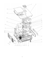
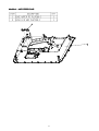
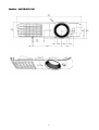
5.1 Product Exploded View .......................................................................................................... 71
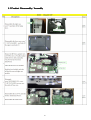
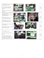
5.2 Product Disassembly / Assembly ........................................................................................... 76
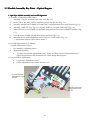
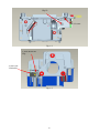
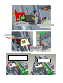
5.3 Module Assembly Key Point - Optical Engine ...................................................................... 80
5.4 Module Assembly Key Point - Mechanical ............................................................................ 92
5.5 Block Diagram ...................................................................................................................... 110
5.6 Trouble shooting ................................................................................................................... 111
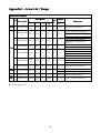
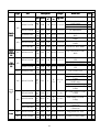
Appendix 1 – Screw List / Torque ...........................................................
........................................................... 120
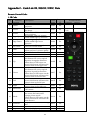
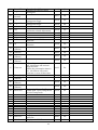
Appendix 2 - Code List: IR / RS232 / DDC Data ....................................
.................................... 122
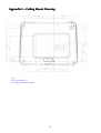
Appendix 3 – Ceiling Mount Drawing ...................................................
................................................... 132
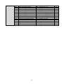
Update History
Revision
Rev. 00a
Rev. 00b
Rev. 00c
Rev. 00d
Chapter
Changes
Date
Initial version
(1) Remove MAC code recovery section for no
MAC address in this model.
(2) Update Extension BD FW download SOP
Modify DDC data
Add Ring Zoom assembly note in p.90 & 91
2
2012/10/11
2012/11/12
2013/03/13
2013/03/28
1. Abbreviations
Abbreviations & Acronyms
A
A/D
Analog to Digital
B
BenQ
BenQ Corporation
C
C/W
Color Wheel
CM
Concave Mirror
D
DLP
Digital Light Processing / Texas Instruments®
DMD
Digital Micro mirror Device
DVI
Digital Video Interface
DVI-I
Digital Video Interface-Integrated
P
PL
Projection Lens
POM
Pond of Mirrors
R
RS232
Interface Between Data terminal Equipment and
Data Communications Equipment Employing
Serial Binary Data Interchange
S
SVGA
SXGA
Super Video Graphics Array, A screen resolution
of 800 x 600 pixels.
Super XGA. A screen resolution of 1280x1024
pixels.
V
VGA
Video Graphics Array. A screen resolution of
640x480 pixels.
X
XGA
A screen resolution of 1024x768 pixels.
3
2. About This Manual
This manual contains information about maintenance and service of BenQ products. Use this
manual to perform diagnostics tests, troubleshoot problems, and align the BenQ product.
Important
Only trained service personnel who are familiar with this BenQ Product shall perform
service or maintenance to it. Before performing any maintenance or service, the
engineer MUST read the “Important Safety Information”
2.1 Trademark
The following terms are trademarks of BenQ Corporation:
BenQ
Other companies, products, or service names may be the trademarks of their respective companies.
2.2 Introduction
This section contains general service information, please read through carefully. It should be stored
for easy access place.
2.3 Important Service Information
RoHS (2002/95/EC) Requirements – Applied to all countries require RoHS.
The RoHS (Restriction of Hazardous Substance in Electrical and Electronic Equipment Directive) is a
legal requirement by EU (European Union) for the global electronics industry which sold in EU and
some counties also require this requirement. Any electrical and electronics products launched in the
market after June 2006 should meet this RoHS requirements. Products launched in the market
before June 2006 are not required to compliant with RoHS parts. If the original parts are not RoHS
complaints, the replacement parts can be non ROHS complaints, but if the original parts are RoHS
compliant, the replacement parts MUST be RoHS complaints.
If the product service or maintenance require replacing any parts, please confirming the RoHS
requirement before replace them.
4
2.4 Safety Notice
1
2
3
4
5
6
7
8
9
Make sure your working environment is dry and clean, and meets all government safety
requirements.
Ensure that other persons are safe while you are servicing the product.
DO NOT perform any action that may cause a hazard to the customer or make the product
unsafe.
Use proper safety devices to ensure your personal safety.
Always use approved tools and test equipment for servicing.
Never assume the product’s power is disconnected from the mains power supply. Check that it is
disconnected before opening the product’s cabinet.
Modules containing electrical components are sensitive to electrostatic discharge (ESD). Follow
ESD safety procedures while handling these parts.
Some products contain more than one battery. Do not disassemble any battery, or expose it to
high temperatures such as throwing into fire or it may explode.
Refer to government requirements for battery recycling or disposal.
2.5 Compliance Statement
Caution: This Optical Storage Product contains a Laser device. Refer to the product specifications and
your local Laser Safety Compliance Requirements.
2.6 General Descriptions
This Service Manual contains general information. There are 2 levels of service:
Level 1: Cosmetic / Appearance / Alignment Service
Level 2: Circuit Board or Standard Parts Replacement
2.7 Related Service Information
Service Web Site
BenQ Global Service Website: http://www.benq.com/support/
eSupport Website: http://esupport.benq.com/v2
5
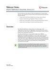
3. Product Overview
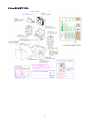
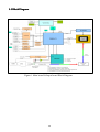
The projector consists of DLP projector controller, Lamp controller, Power supply system, and
System cooling controller. The DLP controller captures digital PC data and video data and then
converts them into the DMD display device. The Lamp controller dominates the lamp’s power and
synchronizes its frequency with color display sequence. The Power supply unit controls the AC line
power factor and converts primary voltage to secondary low voltages for digital board. The System
cooling controller drives the airflow to quench the lamp’s heat and electrical component’s heat.
Specification Overview
1.0 Panel Information
2.0 Projection Lens Specification
3.0 Optical Specification
4.0 Lamp Specification
5.0 Mechanical Specification
6.0 Packaging
7.0 Thermal Specification
8.0 Power Requirements
9.0 Compatibility
10.0 User Interface
11.0 Regulatory
12.0 Reliability
13.0 Other Feature
Input / Output Connectors
1. Input Terminals
2. Output Terminals
3. Control Terminals and Interface
Accessories
Environmental
Electrical Specification
Power Supply Specification
UI Specification
6
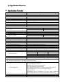
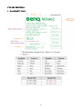
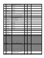
3.1 Specification Overview
Specification Overview
MX662
Version: 01
Item
Specification
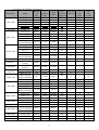
1.Panel Information
1.1 Panel Type
0.55” XGA 2xLVDS 450 DMD
1.2 Package Type
450 series
1.3 Size
0.55”
1.4 Pixels
1024(H) x 768(V)
1.5 Color Depth
30 Bits (1.07 Billion Colors)
1.6 Driver Type
DDP 4421
1.7 Panel Pixel Quality
Follow TI spec.
1.8 Image Imperfection
Follow TI spec.
2. Projection Lens Specification (For Reference)
Wide
Tele
2.1 F/#
2.56
2.8
2.2 Zoom Ratio
1.1±2%
2.3 Throw Ratio
1.86~2.04(53"±3% @ 2m)
2.4 True Zoom
NA
Wide:
Tele:
2.5 Focal Length
21 mm
23.1
2.6 Offset
120%±5%
2.7 Visible Focus Range
1~8m
2.8 Clearly Focus Range
1.5~6 m
2.9 Keystone Distortion
<1%
2.9 TV Distortion
<1%
2.10 Screen Distortion
|A,B| <=3mm, |C|<=2.5 mm @ 60"
2.11 Zoom Ring Torque
30~170g. (Follow Vendor Lens SPEC)
2.12 Focus Ring Torque
30~170g (Follow Vendor Lens SPEC)
2.13 2.13 Lens offset Position
N.A.
2.14 Zoom&Focus shaking level
Follow typical sample (When needed)
2.15 Lens Shift Shaking Level
N.A.
Center @ 49”
All other area
R-G
<2/3 pixel
<1.0 pixel
2.16 Lateral Color
B-G
<2/3 pixel
<1.0 pixel
R-B
<1.0 pixel
<1.0 pixel
2.17 color wheel segment
R80Y30W60C30B75G85
2.18 color wheel speed
50HZ 2X 60H 2X
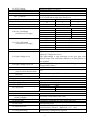
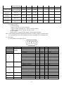
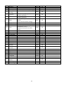
3.Optical Specification
Test under 60” (diagonal) image size with Wide projection lens position.
Reference Meter: Vendor Factory CL-200 Meter (SN head:81531011, body:82521013)
3.1 ANSI Brightness
3.2 ANSI (-) uniformity
3.3 ISO Uniformity
Optical Brightness:
Normal: Minimum 2800 lm
Normal: Typ 3150 lm (For reference)
ECO: Typ 2500 lm (For reference)
*PC Digital Input(HDMI) = Optical native(DMD-full-on)
*PC Analog Input(VGA)≧97% of Optical Native
(DMD-full-on)
*Brightness with PC-HDMI(or PC-VGA) input compared
with “DMD-full-on” need to be provided @ EVT2 & PVT.
Minimum -45%
Minimum 70%
7
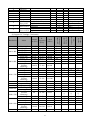
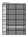
3.4 ANSI Contrast
3.5 FOFO Contrast
3.7 FOFO Contrast with DB
3.8 Focus Quality
3.8.1 区 Pattern
3.8.2
Defocus (Maximum)
Flare (Maximum)
3.9 Focus unbalance
3.10 Color Coordinate
(Confirm at PVT stage)
3.11 Color Uniformity
(Confirm at PVT stage)
3.12 Color Gamut(Compare to NTSC)
3.13 Light Leakage in AA
3.14 Light Leakage out of AA
Minimum 150:1
Minimum 8000:1 (w/ WCE3)
N.A.
(1) The pattern can be uniformly focused – then pass!
(2) If it’s difficult to judge, then check 3.8.2
R
R
R
3.5
3
3
4
4
4
Max. 50cm
Color
x
y
White
0.311±0.02
0.364±0.02
Red
0.627±0.04
0.357±0.04
Green
0.339±0.04
0.570±0.04
Blue
0.147±0.03
0.068±0.03
Color
△uv
White
≦0.02
Red
≦0.02
Green
≦0.02
Blue
≦0.02
Typical 60%
△△0.5 lux compared with center point @ full black pattern
within 60” (Diagonal at 2.3m).
This light-leakage is only described as the spot light with
obvious shape. The uniformity difference of black pattern is
not included.
△0.5 lux, @ full black pattern with 60”~80“(Diagonal at 2.3m)
(Except DMD Defect)
Follow limited sample (When needed).
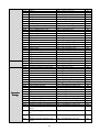
3.15 Ghost
3.16 Lens Shift Speed(sec)
N.A.
(only for motorized len shift)
3.17 Defect (Color Band, Dark Corner, Follow limited sample (When needed).
Dark band)
3.18 Preset mode setting
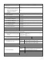
4.Lamp Specification
4.1 Lamp
4.2 Lamp Sync Type
4.3 Lamp Flick
4.4 Lamp Power
5. Mechanical Specification
5.1 Color & Texture specifications
5.2 Physical Dimensions(Width X
Depth X Height)
5.3 Gross Weight
5.4 Security Slot
5.5 Lens Cover
5.6 Adjustment Feet
5.7 Ceiling Mounting
Osram P-VIP 240W/0.8 E20.9n
AC Lamp
Follow limited sample (When needed).
Normal Mode
240W
ECO Mode
190W
ECO BLANK Mode Min 72W
Refer to ID document for details
311.81mm x 244.12mm x 104.7mm
<2.8kg
Kensington compatible slot 20Kg break away force
Detached lens cover
Fast adjustable foot in front, Adjustable foot in rear.
Front/ Rear foot Tilt: 0-8∘,Right/Left: +2.2∘/-0.5
Match BenQ’s ceiling mount required.
∘
8
5.8 Screws
Use the same mounting as current shipping projectors.
All color of screws should similar with the plastic color which
close it.
5.9 During PVT stage, limited sample
of color and texture should be
approved by BenQ industrial
N/A
designer and mechanical
engineer.
6. Packaging
Refer to packing description (Internal :Refer to B405
6.1 Box Dimension
document)
6.2 Net Weight (Esti.)
<2.9kg
6.3 Gross Weight (Esti.)
< 3.85 kg (Including Accessories, Projector)
Refer to packing description (Internal :Refer to B405
6.4 Container Loading (40')
document)
Refer to packing description (Internal :Refer to B405
6.5 Container Loading (20')
document)
Refer to packing description (Internal :Refer to B405
6.6 Packaging Conceptual
document)
Refer to packing description (Internal :Refer to B405
6.7 Container Layout
document)
Refer to packing description (Internal :Refer to B405
6.8 Cushion Orientation
document)
6.9 Cushion Material
EPE
6.10 Box Compression Test
N/A
6.11 Carton Artwork
Refer Packing Description and Appearance Description
7. Thermal Specification
Mechanical component temperature at ambience 0~40℃
Normal surface:
7.1 Surface held or touched for short Metal< 60 ℃ Plastic< 85 ℃
periods
Bottom surface @25℃
Metal< 55 ℃ Plastic< 70 ℃
Metal
Plastic
7.2 Surface which my be touched
< 70 ℃
< 95 ℃
7.3 Exhaust Air
< 95 ℃
Normal mode: 33dBA @ 25°C(table center)
Typical
Eco mode: 30dBA @ 25°C(table center)
7.4 Audible Noise Level
Normal mode: 35dBA @ 25°C(table center)
Max.
Eco mode: 32dBA @ 25°C(table center)
7.5 Fan Numbers
4
8.0 Power Requirements
8.1 Power Supply (Normal)
VAC 100 ~ 240 (50/60Hz)
Max.
375W
0.5W Max. at 100 ~ 240VAC
Standby
(disable loop through, LAN control function,
Pixelwork function and Audio out)
8.2 Power consumption
Normal
Typical 353W@110Vac
ECO
Typical 292W@110Vac
ECO Blank Minimum 150W@110Vac
8.3 Power Connector
IEC 60320 C14
8.4 Power Switch
No
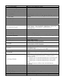
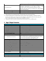
9.0 Compatibility
9
9.1 Data Compatibility(Version 03)
9.1.1 RGB Digital
9.1.2 RGB Analog
9.1.3 Macintosh
9.2 Video Compatibility(Version 03)
9.2.1 SDTV
9.2.2 EDTV
9.2.3 HDTV
9.2.4 Video
9.3 Frequency
9.3.1 H-Sync
9.3.2 V-Sync
9.4 DDC
10.0 User Interface
10.1 Operator Keypad
10.2 LED Indicators
10.2.1 Power On/Off Status
10.2.2 Lamp Status
10.2.3 Temperature Status
10.3 Electric Keystone
10.4 Remote Control
11.0 Regulatory
11.1 Safety
11.2 EMC
11.3 ESD
11.4 GP
Refer to 2.1.4 HDMI/DVI Input
Refer to 2.1.5 PC Input
MAC 13/16/19/21
480i/576i
480P/576P
720@50P/60P,1080@50i/60i/50p/60p/24p/25p/30p
NTSC/ NTSC4.43/ PAL (Including PAL-M, PAL-N)/ SECAM/
PAL60/
15K~102KHz
23 ~ 120 Hz
EDID 1.3
10 Keys:
Power ; Source ; Auto ; Eco Blank ; Mode/Enter ; Menu/Exit ;
Right/ Volume+ ; Left/Volume- ; Up(Keystone+) ;
Down(Keystone-)
3 LEDS
Refer to 4.4 LED definition
Refer to 4.4 LED definition
Refer to 4.4 LED definition
Horizontal and Vertical keystone and adjustable range ±40°(It
will be updated in EVT0 stage)
5F.261Q5.041 x 1
Vendor: Refer to RFQ
Internal: Refer to B106 document
Vendor: Refer to RFQ
Internal: Refer to B106 document
Follow IEC 61000-4-2 and EN55024 regulation
1.BenQ restriction of Hazardous Substance Guideline
(SUP-QM-07-02)
2.Other GP control items please refer PRR
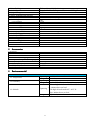
12.0 Reliability
12.1 MTBF
12.2 Lamp Lifetime
12.2.1 Normal Mode
12.2.2 ECO Mode
12.2.3 Smart ECO Mode
13.0 Other Feature
13.1 Color Temperature at Normal
13.2 Digital Zoom
13.3 Aspect Ratio
13.4 Projection Methods
40000 hours except DMD chip, Color wheel, Lamp and Fan,
Ballast
1). Lamp hour = Total lamp hour= X(hours used in Normal
mode) + Y(hours used in Eco mode) + Z(hours used in
SmartEco mode)
X= lamp life spec of SmartEco/lamp life spec of Normal mode
Y= lamp life spec of SmartEco/lamp life spec of Eco mode
Z= lamp life spec of SmartEco/lamp life spec of SmartEco
mode.
2). 50% of Projectors will have 50% Initial Minimum
Brightness
3500 hrs
5000 hrs
6000 hrs
5500/6500/7500/9300K
PC: max 2X, Video: max 1.8X
Auto / Real / 4:3 / 16:9/ 16:10
Floor Front/Ceiling Front/Floor Rear/Ceiling Rear
10
13.5 3D Display
13.5.1 3D test condition
13.6 LAN
13.6.1 LAN-Crestron eControl
13.6.2 LAN-RoomView compatible
13.6.3 LAN-PJ Link compatible
13.6.4 LAN-AMX compatible
13.6.5 LAN-Display (1 to 1)
13.6.6 LAN over RS232
13.7 Certificate
13.7.1 SRS Certificate
13.7.2 Win7 Certificate
13.7.3 WEEE Certificate
13.7.4 Crestron Certificate
13.8 WCE3.0**
13.9 Screen Savor Mode**
(Eco Blank & Lamp Saver)
Yes, support DLP 3D
For Video application
1. Screen size:160 吋
2. 3D Goggle distance : 6M
3. Content : Samsung 3D Demo
4. 3D Goggle : BenQ provide
5. Lamp mode : Eco mode
No
No
No
No
Wireless Lan
No
NA
Yes
Yes
No
1. WCE will activate, if below conditions is fulfilled:
(1)Input PC Source,
(2)Dynamic mode,
(3)Normal Lamp Power
(4)RGB level <5% and last for 10 second
The lamp power will dim to Lamp Dimmest Power (follow
Lamp Capability).
Turn on Eco Blank:
1. When user presses the button once, the image would turn
to Eco Blank mode and show "Eco Blank" and other words
in the bottom of screen.
2. The lamp power will dim to Lamp Dimmest Power (follow
Lamp Capability).
Turn off Eco Blank:
1. When the image is in Eco Blank mode and user done:
(1) Press any Keypad
(2) Press IR
The projector would turn off Eco Blank mode
2. The lamp power will back to original mode power
Turn on Lamp Saver:
1. When there is no signal input and didn’t do any projector
operation last to 3 mins, a full black pattern will be
displayed with “No single” and other message
2. The lamp power will dim to Lamp Dimmest Power (follow
Lamp Capability).
Turn off Lamp Saver:
1. When the image is in Lamp Saver mode and user done:
(1) Press any Keypad
(2) Input Signal
(3) Press IR
The projector would turn off Lamp Saver mode
11
13.10 Smart ECO*
2. The lamp power will back to original mode power
1. When the Smart ECO Mode is activated, lamp power will be
changed automatically in the range of 100% ~ 70%
(240W~170W) power based upon the input content.
2. When user press this key on remote, the "Lamp Settings"
OSD will be pop-up.
NA
13.11 Off-line cooling
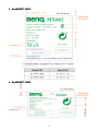
14.0 Green Eco Design
14.1BenQ ecoFACTS
Refer to BenQ ecoFACTS Checking list
“* *”
1. These mode only can operation after 3 min from start-up or recovery operation.
2. To dim the lamp power at Lamp Dimmest Power (follow Lamp Capability) is limited in 30mins
duration and needs to go to Eco power 6 mins obligatory and automatically. After 6min, lamp will
dim to Lamp Dimmest Power (follow Lamp Capability) continue.
3. Lamp power from one mode to another mode need around 10 sec to stabilize power
Input / Output
Output Connectors
1.Input Terminals
1.1 Computer Input - 1
1.2 Computer Input - 2
1.3 Video
1.4 S-Video
1.5 Component - 1
1.6 Component - 2
1.7 DVI - 1
1.8 DVI - 2
1.9 HDMI Digital Video – 1
1.9.1 Support Audio Input
1.9.2 CEC control
1.9.3 HDMI Receive Distance
1.10 HDMI Digital Video – 2
1.10.1 Support Audio Input
1.10.2 CEC control
1.11 Audio Input – 1 (RCA R &L)
1.11.1 Related Source
1.12 Audio Input – 2 (Mini Jack)
1.12.1 Related Source
1.12.2 Input Signal Level
1.13 Audio Input – 3 (Mini Jack)
1.13.1 Related Source
1.13.2 Input Signal Level
1.14 Audio Input – 4 (Mini Jack)
1.15 USB Input
1.16 LAN Input
2.Output Terminals
2.1 Computer Output
2.1.1 Signal Source
RGB DB-15 x 1 (Female Type)
RGB DB-15x 1 (Female Type)
Composite Video (RCA X 1)
S-Video (Mini Din) X 1
RGB DB-15 x 1 (Female Type)
RGB DB-15 x 1 (Female Type)
NA
NA
HDMI 1.4 x1 ( HDCP )
YES
No
Deep color 10bit : 15m
The test HDMI cable is qualified between BenQ and Vendor
The test source instrument is 22294 (HDCP is off)
The test source instrument is PS3 (HDCP is on)
NA
NA
NA
RCA Audio Jack right and left
Video/S-Video audio input
Φ3.5mm Stereo Mini-Jack x 1
Computer / Component audio input
500mVrms 10 KΩ
NA
NA
NA
NA
Type A x1 ( USB Reader & Wireless Display )
Mini Type B x 1 (Display)
NA
RGB DB-15 x 1 (Female Type)
loop through Computer Input -1
12
2.2 Audio Output
2.2.1 Signal Source
2.3 Speaker
2.3.1 Amplifier
3.Control Terminals and Interface
3.1 IR Receiver
3.1.1 Angle
3.1.2 Distance
3.2 USB
3.2.1 FW Upgrade
3.2.2 Mouse Control
3.2.3 USB Display
3.3 RS-232
3.3.1 FW Upgrade
3.3.2 Control Command
3.4 Lan Control
3.5 12V Trigger (Screen Control)
3.5.1 Driving Power
3.5.2 Overload Protection
3.6 Wired Remote Control
Φ3.5mm Mono Mini-Jack x 1
Shared with all audio Input and Power on/off Ring Tone
2W X 1
1W
IR Receiver x2 (Front , Top )
±40°
0~8m
Yes
Page up/down
Yes
D-Sub 9 Pins x 1, male Type
Yes
Yes
No
No
No
No
No
Accessories
1.Accessory
1. Power Cord 3m
2. VGA Cable 1.8m
3. CD x 1 (24 Language)
4. Quick-Start_Card (18Language)
5. Remote Control
6. Carry Case
7. Warranty Card
8. Adapter
X1
X1
X1
X1
5F.261Q5.041 x 1 ( New remote )
N/A
By SKU
N/A
Environmental
1.Environmental
1.1 Temperature
1.2 Humidity
1.3 Altitude
Operating
Storage
Operating
Storage
Operating
Storage
13
0~40°C, without condensation
-20~60°C, without condensation
10~90%RH, without condensation
10~90%RH, without condensation
Without high altitude mode 0°C~35°C @
0~1499m above sea level
With high altitude mode 0°C~30°C @
1500~3000m above sea level
30℃@0~12,200m above sea level
Electrical Specification
1.1 Electrical Interface Character
1.1.1 Composite Video Input : N/A
(1) Pin definition (RCA Jack)
(2) Signal Level:
Signal
Parameter
CVBS
Amplitude, total (video+ sync)
Luminance
Amplitude, video
Amplitude, sync
Impedance
Min
(3) Support Timings: (Version 03)
Horizontal
Vertical
Video mode
frequency
frequency
(KHz)
(Hz)
NTSC
15.73
60
PAL
15.63
50
SECAM
15.63
50
PAL-M
15.73
60
PAL-N
15.63
50
PAL-60
15.73
60
NTSC4.43
15.73
60
Type
1
0.7
0.3
75
Sub-carrier
Frequency
(MHz)
3.58
4.43
4.25 or 4.41
3.58
3.58
4.43
4.43
Max
Volts peak to peak
Volts peak to peak
Volts peak to peak
ohm
User Manual
Supported
3D Field
Sequential
Yes
Yes
Yes
Yes
Yes
Yes
Yes
◎
1.1.2 S-Video Input
(1) Pin definition (Mini Din)
4-pin Mini Din Connector
(2) Signal Level:
PIN
Signal
Parameter
Min
1
GND
2
GND
3
CVBS Luminance Amplitude, total (video+ sync)
Amplitude, video
Amplitude, sync
Impedance
Amplitude (for NTSC)
4
CVBS chroma Amplitude (for PAL/SECAM)
Impedance
14
Type Max
1
0.7
0.3
75
286
300
75
Volts peak to peak
Volts peak to peak
Volts peak to peak
ohm
m Volts peak to peak
m Volts peak to peak
ohm
(3) Support Timings: (Version 03)
Horizontal
Vertical
Video mode
frequency
frequency
(KHz)
(Hz)
NTSC
15.73
60
PAL
15.63
50
SECAM
15.63
50
PAL-M
15.73
60
PAL-N
15.63
50
PAL-60
15.73
60
NTSC4.43
15.73
60
Sub-carrier
Frequency
(MHz)
3.58
4.43
4.25 or 4.41
3.58
3.58
4.43
4.43
User Manual
Supported
3D Field
Sequential
Yes
Yes
Yes
Yes
Yes
Yes
Yes
◎
1.1.3 Component Video Input
(1) Pin definition { RGB DB-15 x 1 (Female Type) }
5
1
6
10
15
11
(2) Signal Level:
Pin
Signal
Parameter
1
Pr DATA
Impedance
Pb DATA
3
Black pedestal
Y DATA_SOG Impedance
Amplitude
2
Video amplitude
Sync amplitude
Black pedestal
6
Red GND
7
Green GND
8
Blue GND
Min
(3) Support Timings: (Version 03)
Horizontal
Vertical
Timing Resolution
frequency
Frequency (Hz)
(KHz)
480i
720 x 480
15.73
59.94
480p
720 x 480
31.47
59.94
576i
720 x 576
15.63
50
576p
720 x 576
31.25
50
720/50p 1280 x 720
37.5
50
720/60p 1280 x 720
45.00
60
1080/50i 1920 x 1080
28.13
50
1080/60i 1920 x 1080
33.75
60
1080/24P 1920 x 1080
27
24
1080/25P 1920 x 1080
28.13
25
1080/30P 1920 x 1080
33.75
30
1080/50P 1920 x 1080
56.25
50
1080/60P 1920 x 1080
67.5
60
15
Type
75
0
75
1
0.7
0.3
0
Dot Clock
Frequency
(MHz)
13.5
27
13.5
27
74.25
74.25
74.25
74.25
74.25
74.25
74.25
148.5
148.5
Max
Ohm
Volts
Ohm
Volts peak-to-peak
Volts peak-to-peak
Volts peak-to-peak
Volts
User
Manual
Supported
Yes
Yes
Yes
Yes
Yes
Yes
Yes
Yes
Yes
Yes
Yes
Yes
Yes
3D Field
Sequential
◎
1.1.4 HDMI/DVI Input
- HDMI 1.3 Compliance
- DVI 1.0 Compliance
- HDCP 1.1 Compliance
(1) Pin definition
Pin
1
2
3
4
5
6
7
8
9
10
11
12
13
14
15
16
17
18
19
Signal
TMDS Data2+
TMDS Data2 Shield
TMDS Data2–
TMDS Data1+
TMDS Data1 Shield
TMDS Data1–
TMDS Data0+
TMDS Data0 Shield
TMDS Data0–
TMDS Clock+
TMDS Clock Shield
TMDS Clock–
CEC
Reserved (N.C. on device)
SCL
SDA
DDC/CEC Ground
+5 V Power (max 50 mA)
Hot Plug Detect
(2) Support Video Timings: (Version 03)
User 3D Field
3D
Horizontal Vertical Dot Clock
Timing
Resolution
frequency frequencyFrequency Remark Manual Sequential over(KHz)
(Hz) (MHz)
Supported
under
HDMI only Yes
480i
720(1440) x 480
15.73
59.94
27
◎
480p
720 x 480
31.47
59.94
27
HDMI only Yes
576i
720(1440) x 576
15.63
50
27
HDMI/DVI Yes
576p
720 x 576
31.25
50
27
HDMI/DVI Yes
720/50p
1280 x 720
37.5
50
74.25 HDMI/DVI Yes
◎
◎
720/60p
1280 x 720
45.00
60
74.25 HDMI/DVI Yes
◎
◎
1080/24P
1920 x 1080
27
24
74.25 HDMI/DVI Yes
◎
◎
1080/25P
1920 x 1080
28.13
25
74.25 HDMI/DVI Yes
1080/30P
1920 x 1080
33.75
30
74.25 HDMI/DVI Yes
1080/50i
1920 x 1080
28.13
50
74.25 HDMI/DVI Yes
1080/60i
1920 x 1080
33.75
60
74.25 HDMI/DVI Yes
1080/50P
1920 x 1080
56.25
50
148.5 HDMI/DVI Yes
1080/60P
1920 x 1080
67.5
60
148.5 HDMI/DVI Yes
16
3D
sideby-side
◎
◎
(3) Support PC Timings: (Version 03)
Refresh
HResolution
Mode
rate frequency
(Hz)
(kHz)
VGA_60
59.940
31.469
VGA_72
72.809
37.861
640 x 480
VGA_75
75.000
37.500
VGA_85
85.008
43.269
VGA_120**
119.518 61.910
720 x 400
720x400_70
70.087
31.469
SVGA_60
60.317
37.879
SVGA_72
72.188
48.077
SVGA_75
75.000
46.875
800 x 600
SVGA_85
85.061
53.674
SVGA_120
119.854 77.425
(Reduce Blanking)
XGA_60
60.004
48.363
XGA_70
70.069
56.476
XGA_75
75.029
60.023
1024 x 768
XGA_85
84.997
68.667
XGA_120
119.989 97.551
(Reduce Blanking)
1152 x 864
1152 x 864_75
75.00
67.500
BenQ Notebook
1024x576
60.00
35.820
Timing
BenQ Notebook
1024x600
64.995
41.467
Timing
1280 x 720_60
60
45.000
1280x720
1280x720_120
120
90.000
1280 x 768_60
60
47.396
1280 x 768 (Reduce Blanking)
1280 x 768_60
59.870
47.776
WXGA_60
59.810
49.702
WXGA_75
74.934
62.795
1280 x 800
WXGA_85
84.880
71.554
WXGA_120
119.909 101.563
(Reduce Blanking)
SXGA_60
60.020
63.981
1280 x 1024
SXGA_75
75.025
79.976
SXGA_85
85.024
91.146
1280 x 960_60
60.000
60.000
1280 x 960
1280 x 960_85
85.002
85.938
1360 x 768
1360 x 768_60
60.015
47.712
WXGA+_60
60
55.469
1440 x 900 (Reduce Blanking)
WXGA+_60
59.887
55.935
1400X1050
SXGA+_60
59.978
65.317
1600x1200
UXGA
60.000
75.000
1680x1050
1680x1050_60
59.883
64.674
17
Clock
(MHz)
25.175
31.500
31.500
36.000
52.500
28.3221
40.000
50.000
49.500
56.250
83.000
65.000
75.000
78.750
94.500
115.500
108.000
46.996
51.419
74.250
148.500
68.25
79.5
83.500
106.500
122.500
146.25
108.000
135.000
157.500
108
148.500
85.500
88.75
106.500
121.750
162.000
119.000
User
3D Field
Manual Sequential
Supported
Yes
◎
Yes
Yes
Yes
Yes
Yes
Yes
◎
Yes
Yes
Yes
Yes
◎
Yes
Yes
Yes
Yes
Yes
◎
3D
overunder
◎
3D
sideby-side
◎
◎
◎
◎
◎
◎
Yes
Yes
Yes
Yes
No
No
◎
◎
◎
◎
◎
◎
◎
Yes
Yes
Yes
Yes
Yes
◎
◎
◎
◎
◎
◎
◎
◎
◎
◎
◎
Yes
Yes
Yes
Yes
Yes
Yes
No
◎
◎
◎
◎
Yes
Yes
Yes
No
◎
◎
◎
◎
◎
◎
◎
◎
(Reduce Blanking)
1680x1050_60
59.954
1920x1200_60
1920 x 1200
59.950
(Reduce Blanking)
640x480
MAC13
66.667
@67Hz
832x624
MAC16
74.546
@75Hz
1024x768
MAC19
75.020
@75Hz
1152x870
MAC21
75.06
@75Hz
65.290
146.250
74.038
154.000
35.000
30.240
49.722
57.280
60.241
80.000
68.68
100.00
Yes
No
◎
◎
◎
◎
Yes
Yes
Yes
Yes
(4) Support Audio:
(a) HDMI Mode:
- Support LPCM, two audio channels
- Support audio sampling rate : 32kHz, 44.1kHz, 48kHz
- Support audio bit rate : 16 bits, 20 bits, 24 bits
(b) DVI Mode:
Analog audio is supported through PC audio input terminal.
Note. There timing showing depend the EDID file and VGA graphic card limitation.
It is possible that user cannot choose the above timings on VGA display card.
1.1.5 PC Input
(1) Pin definition and Signal Level:
5
1
6
10
15
11
Pin
1
2
3
2
13
14
12
15
4
Signal
RDATA
GDATA
BDATA
Parameter
Impedance
Amplitude
Black pedestal
Pixel Clock
GDATA_SOG Impedance
Amplitude
Video amplitude
Sync amplitude
Black pedestal
Pixel Clock
HDATA
Impedance
Amplitude, low level
Amplitude, high level
Frequency
VDATA
Impedance
Amplitude, low level
Amplitude, high level
Frequency
SDADATA
Amplitude, low level
Amplitude, high level
SCLDATA
Amplitude, low level
Amplitude, high level
NC
18
Min
Type
75
0.7
0
170
75
1
0.7
0.3
0
170
1
0
2.5
31
1
0
2.5
48
0
2.5
0
2.5
Max
Ohm
Volts peak-to-peak
Volts
M Hz
Ohm
Volts peak-to-peak
Volts peak-to-peak
Volts peak-to-peak
Volts
M Hz
K ohm
0.5 volt
5 Volt
102 K Hz
K ohm
0.8 volt
5 Volt
120 Hz
0.8 volt
5 Volt
0.8 volt
5 Volt
5
6
7
8
9
10
11
2
1
3
NC
Red GND
Green GND
Blue GND
DDCP 5V
Sync. Return
GND
G DATA
Share with Y
R DATA
Share with Pr
B DATA
Share with Pb
5
Amplitude (with sync)
Impedance
Amplitude
Impedance
Amplitude
Impedance
Volts
1
75
0.7
75
0.7
75
Volts peak to peak
ohm
Volts peak to peak
ohm
Volts peak to peak
ohm
(2)Support PC Timings: (Version 03)
640 x 480
800 x 600
1024 x 768
1152 x 864
1024 x 576
1024 x 600
1280x720
1280 x 768
1280 x 800
1280 x 1024
70.087
59.940
72.809
75.000
85.008
60.317
72.188
75.000
85.061
31.469
31.469
37.861
37.500
43.269
37.879
48.077
46.875
53.674
28.3221
25.175
31.500
31.500
36.000
40.000
50.000
49.500
56.250
119.854
77.425
83.000
60.004
70.069
75.029
84.997
48.363
56.476
60.023
68.667
65.000
75.000
78.750
94.500
119.989
97.551
115.500
75.00
60.0
64.995
60
120
67.500
35.820
41.467
45.000
90.000
108.000
46.966
51.419
74.250
148.500
60
47.396
68.25
59.870
59.810
74.934
84.880
47.776
49.702
62.795
71.554
79.5
83.500
106.500
122.500
119.909
101.563
146.25
60.020
63.981
108.000
19
Yes
Yes
Yes
Yes
Yes
Yes
Yes
Yes
Yes
Yes
Yes
Yes
Yes
Yes
Yes
Yes
Yes
Yes
Yes
No
No
Yes
Yes
Yes
Yes
Yes
Yes
3D sideby-side
720x400_70
VGA_60*
VGA_72
VGA_75
VGA_85
SVGA_60*
SVGA_72
SVGA_75
SVGA_85
SVGA_120**
(Reduce
Blanking)
XGA_60*
XGA_70
XGA_75
XGA_85
XGA_120**
(Reduce
Blanking)
1152 x 864_75
BenQ NB Timing
BenQ NB Timing
1280 x 720_60*
1280x720_120**
1280 x 768_60*
(Reduce
Blanking)
1280 x 768_60*
WXGA_60*
WXGA_75
WXGA_85
WXGA_120**
(Reduce
Blanking)
SXGA_60***
Clock
(MHz)
3D
over-under
720 x 400
HRefresh frequency
rate (Hz) (kHz)
3D frame
sequential
Mode
User anual
Supported
Resolution
◎
◎
◎
◎
◎
◎
◎
◎
◎
◎
◎
◎
◎
◎
◎
◎
◎
◎
◎
◎
◎
◎
◎
◎
◎
◎
◎
1280 x 960
1360 x 768
1440 x 900
1400X1050
1600x1200
1680 x 1050
SXGA_75
SXGA_85
1280 x 960_60***
1280 x 960_85
1360 x 768_60***
WXGA+_60***
(Reduce
Blanking)
WXGA+_60***
SXGA+_60***
UXGA***
1680x1050_60***
(Reduce
Blanking)
1680x1050_60***
75.025
85.024
60.000
85.002
60.015
79.976
91.146
60.000
85.938
47.712
135.000
157.500
108
148.500
85.500
60
55.469
88.75
59.887
59.978
60.000
55.935
65.317
75.000
106.500
121.750
162.000
59.883
64.674
119.000
59.954
65.290
146.250
Yes
Yes
Yes
Yes
Yes
No
Yes
Yes
Yes
No
Yes
Yes
◎
◎
◎
◎
◎
◎
◎
◎
◎
◎
◎
◎
◎
◎
◎
◎
640x480
MAC13
66.667
35.000
30.240
@67Hz
832x624
Yes
MAC16
74.546
49.722
57.280
@75Hz
1024x768
Yes
MAC19
74.93
60.241
80.000
@75Hz
1152x870
Yes
MAC21
75.06
68.68
100.00
@75Hz
Note. There timing showing depend the EDID file and VGA graphic card limitation.
It is possible that user cannot choose the above timings on VGA display card.
1.1.6 Audio Input (RCAx2)
(1) Pin definition :
(2) Signal Level: N/A
PIN
Signal
1
L Audio
2
R Audio
Parameter
Amplitude
Impedance
Amplitude
Impedance
1.1.7 Audio Input (Mini-Jack φ3.5mm)
(1) Pin definition
20
Min Type Max
0.5 2 VRMS
10
KΩ
0.5 2 VRMS
10
KΩ
(2) Signal Level:
PIN
Signal
1
Audio In Right
2
3
5
4
NC
NC
GND
Audio In Left
Parameter
Amplitude
Impedance
Amplitude
Impedance
Min Type Max
0.5 2 VRMS
10
KΩ
0.5
10
2 VRMS
KΩ
1.1.8 Audio Headphone Output (Phone-Jack φ3.5mm)
(1) Pin definition
(2) Signal Level:
PIN
Signal
Parameter
6
Audio Out Right Amplitude
Impedance
Audio out detect Output ON
7
Output Off
8
NC
5
GND
Audio Out Left
Amplitude
9
Impedance
Min Type Max
32
0.8
mV
Ω
0.2 VDD
VDD
mV
Ω
32
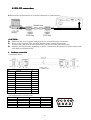
1.1.9 RS232 Control Port
(1) Pin definition (D-Sub 9 Pin)
(2) Signal Level:
PIN
Signal
1
NC
2
RX
3
TX
4
NC
5
GND
6
NC
7
RTSZ
8
CTSZ
9
NC
Parameter
Amplitude (with sync)
Amplitude
21
Min Type Max
-25
-13.2
25
13.2
Volt
Volt
1.1.10 Lan Control Port (Follow IEEE 802.3) : N/A
1.1.11 Screen control output ( DC power jack ) : N/A
1.2 Speaker
Signal
Audio
Parameter
Impedance (audio in)
Amplitude (audio in)
Bandwidth
S/N Ratio
Total Harmonic Distortion
Min
300Hz
40
Type
10
500
Max
Kohm
mVolts rms
16kHz
10
dB
%
Power Supply Specification
1.1 Input Power Specification
Specification
Input Voltage Range
Frequency Range
Regulation Efficiency
Description
The unit shall meet all the operating requirements with the range 90
~ 264 VAC
The unit shall meet all the operating requirements with an input
frequency range 47 Hz ~ 63 Hz
80 % (typical) measuring at 115Vac and full load
1.2 Varistor Requirement
The power supply’s varistor component should withstand 510V or higher power.
1.3 Lamp Power Requirement
Specification
Starting pulse from Igniter
Description
2.1KV Min.
22
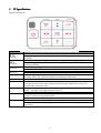
UI Specification
Keypad Description
Key Name
Volume Volume +
5
Keystone +
6
Keystone Source
Power
Auto
Eco Blank
Mode/Enter
Menu/Exit
Detailed Description
1. When there is OSD menu, user can press this key to move to the left item.
2. By pressing “Volume -” button, the volume of the magnified sound will be reduced
gradually.
1. When there is OSD menu, user can press this key to move to right item
2. By pressing “Volume +” button, the volume of the magnified sound will be
increase gradually.
1. When user presses this button once, it will increase the keystone value
2. When there is OSD menu, user can press this key to move to upper item
1. When user presses this button once, it will decrease the keystone value
2. When there is OSD menu, user can press this key to move to next item
User could press this key to call out Source OSD to select search source. After
pressing "Enter" key, system would keep searching selected source
User presses this key once to turn on or off projector
“Auto” will not be active under video input, including video, S-video and Y/Pb/Pr.
The current source info will be displayed at the bottom right of the screen for 3
seconds after users press Auto
1. When user presses the button once, the image would turn to blank and show Eco
Blank message in the right-bottom of screen
2. When the image is blank, user press this key back to normal image
1. When there is no OSD menu, this button is Mode hot key; user would press this
button to choose one of preset modes
2. When there is confirm message, user could press this key to confirm
1. User could press this button to call out OSD
2. When it exits OSD, user could press this button to leave current page or items or to
close OSD.
23
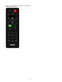
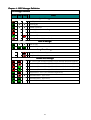
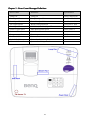
Remote Control Function and Key Code Definition
(Detail See Appendix2)
24
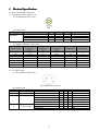
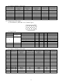
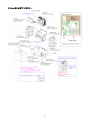
3.2 Packing
【NOTE】The updated Service BOM is on SPO system. Please check it to order service parts.
1. For 9H.J6E77.13A~T,
9H.J6E77.13A~T, exclude D/F/
D/F/K/L
K/L :
25
2. For 9H.J6E77.13D/F
9H.J6E77.13D/F :
26
3. For 9H.J6E77.13K
9H.J6E77.13K :
27
4. For 9H.J6E77.13L
9H.J6E77.13L :
28
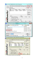
CTN LBL PRINTING:
1. For 9H.J6E77.13A/L
9H.J6E77.13A/L
29
2. For 9H.J6E77.13J/K
9H.J6E77.13J/K
KC label only for 13K:
30
3. For 9H.J6E77.13E
9H.J6E77.13E/U
4. For 9H.J6E77.13D/F
9H.J6E77.13D/F
31
5. For 9H.J6E77.13P/S
9H.J6E77.13P/S
6. For 9H.J6E77.13T
9H.J6E77.13T
32
7. For 9H.J6E77.13C
9H.J6E77.13C
33
SPEC LBL PRINTING:
1. For 9H.J6E77.13x
9H.J6E77.13x, exclude 13
13C/L
34
2. For 9H.J6E77.13L
9H.J6E77.13L
35
3. For 9H.J6E77.13C
9H.J6E77.13C
36
LAMP LBL PRINTING
37
3.3 Customer Acceptance
1.0
1.0 SCOPE
This document establishes the general workmanship standards and functional
acceptance criteria for projector produced by BENQ.
2.0 PURPOSE
The purpose of this publication is to define a procedure for inspection of the
projector by means of a customer acceptance test, the method of evaluation of
defects and rules for specifying acceptance levels.
3.0 APPLICATION
The "Customer Acceptance Criteria" is applicable to the inspection of the projector,
completely packed and ready for dispatch to customers. Unless otherwise specified,
the customer acceptance inspection should be conducted at manufacturer's site.
4.0 DEFINITION
The "Customer Acceptance Criteria" is the document defining the process of
examining, testing or otherwise comparing the product with a given set of specified
technical, esthetic and workmanship requirements leading to an evaluation of the
"degree of fitness for use", including possible personal injury or property damage for
the use of the product.
5.0 CLASSIFICATION OF DEFECTS
The defects are grouped into the following classes:
5.1 Critical defect
A critical defect is a defect which judgment and experience indicate that there is
likely to result in hazardous or unsafe conditions for individuals using product.
5.2 Major defect
defect
A major defect is a defect, other than critical one, is likely to result in failure, or
to reduce materially the usability of the product for its intended purpose.
5.3 Minor defect
38
A minor defect is a defect that is not likely to reduce materially the usability of its
intended purpose, or is a departure from established standards having little
bearing on the effective use of operation of the product.
Note: If BenQ defect undefined failure, and it judged that is reduce the merchandisebility, BenQ
CM Inform this defect. After that parties make communication and decide how to solve.
6.0
EXPRESSION OF DEFECTIVES
Number of defects
Percent of defects = ------------------------------------------ X 100%
Number of products inspected
7.0 INSPECTION STANDARD
Unless otherwise specified, the inspection standard will be defined by MIL-STD-105E,
NORMAL INSPECTION LEVEL Ⅱ, SINGLE SAMPLING PLAN.
7.1 Acceptance Quality Level
7.1.1 Critical
Critical Defect:
When a critical defect is found, this must be reported immediately upon
detection, the lot or batch shall be rejected and further shipments shall be
held up pending instructions from the responsible person in relevant
department.
7.1.2 under
under normal sampling
Critical
Defective :
0% AQL
Major
Defective : 0.65% AQL
Minor
Defective : 2.5% AQL
8.0 GENERAL RULES
8.1 The inspection must be carried out by trained inspectors who have good knowledge about
the product.
8.2 The inspection must be based upon the documents concerning the completely assembled
and packed product.
39
8.3 When more defects appear with the same unit only the most serious defect has to be taken
into account.
8.4 Defects found in accessory packed with the product such as Cable, Connector, Manual, CD
and the like, and being inspected as a part of the complete product, must be included in the
evaluation.
8.5 The evaluation must be within the limits of the product specification and, for not specified
characteristics, refer to the sample machine or the judgment of BENQ QA Engineer. But
any kind of proposals or judgments must be reasonable and acceptable by both sides.
8.6 Faults must be able to be repeatedly demonstrated.
9.0 TEST CONDITIONS
Unless other prescription, the test conditions are as followings:
Nominal voltage: refer to operation manual
Environmental illumination:
Variable from 500 to 800 Lux (For appearance inspection)
Variable from 0 to 7 Lux (For functional inspection)
Temperature: 25±5℃
Visual inspection shall be done with the distance from eyes to the sample 40~50
cm.
Display mode: refer to operation manual
10.0 TEST EQUIPMENTS
Dark room
PC
Pattern Generator: Chroma or equivalent
DVD player
Power supply (100~240 VAC) with consumption meter
Measuring tape
40
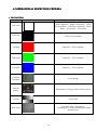
4. Level 1 Cosmetic / Appearance / Alignment Service
4.1 Cosmetic / Appearance Inspection Criteria
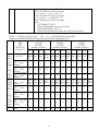
TABLE 1. General Product of plastic outlook of dot, blemish, and others spec inspection standard (产
品一般外观塑料件的黑点、杂质、凸点、砂粒缺陷检验标准)
A 级面
B 级面
C 级面
规格
A surface
B surface
C surface
Spec
(允许数)
(允许数)
(允许数)
(面积 cm2)
(Number of defect)
(Number of defect)
(Number of defect)
( Area cm2 )
100*10
100*1
100*1
20*20 50*50 70*70
20*20 50*50 70*70
20*20 50*50 70*70
0
00
00
2
P < 0.1 mm
不计 不计
不计 不计 不计 不计 不计 不计 不计
不计
不计
不计
杂质 点距 Distance
Ignor Ignor
Ignor Ignor Ignor Ignor Ignor Ignor Ignor
Ignore
Ignore
Ignore
Particle 2cm
e
e
e
e
e
e
e
e
e
2
黑点 0.1△P< 0.2 mm
2
3
4
5
2
3
4
5
4
4
5
6
Blemish 点距 Distance
|
4cm
2
异色点 0.2△P <0.3mm
点距 Distance
0
0
0
0
2
3
4
5
3
4
5
6
4cm
凸点
砂粒
棉絮
毛屑
Particle
|
同色点
Spot
with
same
color
P<0.1 mm2
不计 不计
不计 不计 不计 不计 不计 不计 不计
不计
不计
不计
点 距 Distance
Ignor Ignor
Ignor Ignor Ignor Ignor Ignor Ignor Ignor
Ignore
Ignore
Ignore
2cm
e
e
e
e
e
e
e
e
e
2
0.1△P<0.2mm
4
4
5
6
5
5
6
7
6
6
7
8
点 距 Distance
4cm
0.2△P < 0.3mm2
3
4
4
5
4
5
5
6
6
7
7
8
点 距 Distance
4cm
0.3△P < 0.5mm2
2
2
3
4
3
3
4
5
4
4
5
6
点 距 Distance
5cm
Total
4
4
5
6
5
5
6
7
6
6
7
8
备注 Note:
1. 检测面积 A <20*20 以 20*20 之规范检验之, 20*20≦A<50*50,以 50*50 等级检验之,以此类推.
Use the 20*20 criteria to the area less than 20*20; 50*50 inspection criteria to the area 20*20≦A<50*50;
etc.
杂质/黑点/异色点(Particle/Blemish/Color Spot)
1.1 A、B、C 级面定义请参考 6.2 级面定义。
Definition of surface A, B, C refer to 6.2
1.2 LOGO 周边 2 cm 内不可有 0.05 mm 以上之点, (0.05 mm 以内之点不计)。
Blemish around the logo must be equal or smaller than 0.05 mm
1.3 表面气泡—不可有。
2
2
2
Bubble on the surface is to be reject.
41
TABLE 2 :产品一般外观的塑料件检验标准(General Product of plastic outlook inspection
standard)
NO Appearance
Spec
1 缩水
A 区: 不可有缩水, 以带手套检验, 手摸过去不可有凹
Shrinkage
陷的感觉
A region: No Shrink. With gloves, no feeling of sink when touching the
surface
B / C 区: 不能明显看出
B/C region: not obvious
2 流痕, 咬花, 光泽
不能有明显的深浅不均
Run, Texture, Gloss
No obvious non-uniformity
3 接合线
用指甲划过不会有停顿感,并附近无明显之光泽差异
Welding Line/Knit Line When scratching on it, there’s no feeling of obstruction. Also, there
should not be obvious difference in gloss nearby it.
4 顶白
不可
Ejector Mark
Reject
5 Label/screws shortage
不允许
Reject
6 缺料
缺料不可影响机构强度和表面
Material shortage
Material shortage is not allowed to impact structure strength and
surface
7 色差
喷漆(Painting): ΔE<=2; L<=1.5 ; Δ A,B <= 0.6
Chromatic aberration
银粉漆 (Paint, aluminum).
ΔE<=2 L<=1.0; Δ A, B <= 0.6
非银粉漆(Paint, non-aluminum)
素材(Raw material) : ΔL,A,B<=0.6 ,ΔE<=0.75
8 印刷
文字印刷不得有漏印、断线、重影、组细不均、溢墨、印偏( 1mm )、
Printing
印斜 (歪斜<0.3 mm )。
Printing must not have incomplete printing, break off, overlap,
uneven thickness, excessive ink, printing misalignment
(1mm), printing slanting & crooked (<0.3mm)
文字印刷颜色须确认是否正确 。
Printing color must be comparable to color chip and sample.
9 Logo of panel sticker
文字印刷不得有漏印.断线.重影.组细不均.溢墨.印偏( 1mm)印斜
(歪斜 < 0.5 mm).
Printing must not have incomplete printing, break off, overlap, uneven
thickness, excessive ink, printing misalignment (1mm), printing
slanting & crooked (<0.5mm)
10 刮伤
Scratch/Nicks
文字印刷颜色须确认是否正确.
Printing color must be comparable to color chip and sample.
Side A:
(W < 0.1mm , L < 3mm): 容许 1 个
Only 1 this kind of scratch is accepted
W < 0.1mm , L < 3-5mm 容许 0 个
No this kind of scratch is accepted
Side B:
W < 0.15mm , L < 3mm 容许 2 个
Only less than 2 this kind of scratch is accepted
W < 0.15mm , L < 3-5mm 容许 1 个
Only 1 this kind of scratch is accepted
Side C:
42
W < 0.2mm , L < 1mm 容许 4 个
Only 4 this kind of scratch is accepted
W < 0.2mm , L < 3mm 容许 3 个
Only 3 this kind of scratch is accepted
W < 0.2mm , L < 3-5mm 容许 2 个
Only 2 this kind of scratch is accepted
Note:
刮伤见底材者不允许
Severe scratch which disclose the Natural
1. 刮擦伤两两需相距 5cm 以上
Each scratch should be 5cm more far away from each other
TABLE 3 产品镁铝合金制品之黑点、杂质、凸点、砂粒缺陷检验标准检验规范
(Magnesium-Aluminum Alloy Products that Dot, Blemish, and Others spec.)
A 级面
B 级面
C 级面
规格
A surface
B surface
C surface
Spec
(允许数)
(允许数)
(允许数)
(面积 cm2)
(Number of defect)
(Number of defect)
(Number of defect)
( Area cm2 )
100*10
100*1
100*10
20*20 50*50 70*70
杂质
Particl
e
黑点
Blemis
h
|
异色
点
Color
spot
凸点
砂粒
棉絮
毛屑
Particl
e
|
同色
点
Spot
with
same
color
P < 0.1 mm2
20*20 50*50 70*70
0
00
20*20 50*50 70*70
0
不计 不计 不计
不计 不计 不计 不计 不计 不计 不计
不计
不计
Ignor Ignor Ignor
Ignor Ignor Ignor Ignor Ignor Ignor Ignor
Ignore
Ignore
e
e
e
e
e
e
e
e
e
e
0.1△P< 0.3 mm2
1
2
3
4
2
3
3
5
3
4
5
6
点距 7.5cm
Distance
0.3△P <0.5mm2
0
0
0
0
2
2
3
4
2
3
4
5
点距 7.5cm
Distance
0.5△P <0.7mm2
0
0
0
0
0
0
1
2
1
2
3
4
点距 7.5cm
Distance
P<0.1 mm2
不计 不计 不计
不计 不计 不计 不计 不计 不计 不计
不计
不计
点距 7.5cm
Ignor Ignor Ignor
Ignor Ignor Ignor Ignor Ignor Ignor Ignor
Ignore
Ignore
Distance
e
e
e
e
e
e
e
e
e
e
2
0.1△P<0.3mm
2
2
3
4
3
4
5
6
4
5
6
7
点距 7.5cm
Distance
0.3△P < 0.5mm2
1
1
2
3
2
2
3
4
2
3
3
4
点距 7.5cm
Distance
0.5△P < 0.7mm2
点距 7.5cm
Distance
0
0
1
2
1
1
2
3
1
2
2
3
Total
3
3
4
5
5
6
7
8
6
7
8
9
43
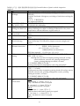
4.2 OPERATIONAL INSPECTION CRITERIA
1. TEST PATTERN
PATTERN
PATTERN
TEST ITEM
ANSI Brightness、Bright Uniformity、FOFO
Contrast Ratio、CIE white coordinate、Throw
Ratio、Zoom Ratio、Distortion
Full white
Full Dark
FOFO Contrast Ratio
Full Red
Impurity、CIE coordinate
Full Green
Impurity、CIE coordinate
Full Blue
Impurity、CIE coordinate
Chromo
Pattern84
Focus Range
General-1
pattern
Performance/ Timing check/ function check
32 Gray
Gray Check
Check the DDC information,
Including S/N, model, manufacturer name,
product code.
DDC check
44
2. TEST CONTENT:
HDTV
NTSC
TEST ITEM
Focus/ Focus range
Impurity, CIE coordinate,
pixel fail
Picture performance
DVD
picture
NTSC disk/ PAL disk
Picture quality
PC Mode
Test Condition
Chroma pattern
FULL W , R , G , B
Input
Equipment
D-SUB
Chroma
YPbPr
Chroma / BS
Tuner
Video
S-video
DVD player
3. SPECIFICATION:
Item
Spec.
ANSI Brightness
Minimum 2800Lumens
Bright Uniformity
Minimum -45%
ANSI Contrast
Minimum 150:1
FOFO Contrast Ratio
Minimum 8000:1
Light Leakage
(In Active Area)
center point within 60”
(Diagonal at 2.3m) image
size
0.5 lux within 60”
80” (Diagonal at 2.3m)
image size
x=0.311+0.02
y=0.364+0.02
x=0.627+0.04
y=0.357+0.04
x=0.339+0.04
y=0.570+0.04
x=0.147+0.03
y=0.068+0.03
Light Leakage
(Out of Active Area)
CIE white coordinate
CIE red coordinate
CIE green coordinate
CIE blue coordinate
Throw Ratio
Keystone Distortion
Vertical TV Distortion
Clearly Focus Range
Gray Check
DMD Image Quality
PC
Video
YPbPr
Condition
△≦0.5 lux compared to
△≦
~
53”±3% Diagonal @ 2M
(W2-W1) / (W1+W2)
<1.0%
(H1+H2-2×H3)/2H2
<1.0%
Pixel clear and uniform at
1.5~6m
Should be clear and bright
See
Defect Classification
640X480 1024X768,
compressed 1600x1200;
NTSC/NTSC4.43/PAL(Incl
uding PAL-M, PAL-n)
/SECAM/PAL60
NTSC (480i)/ 480p/ PAL
(576i)/576p, HDTV
(720P/1080i/p)
45
Contrast: Preset
Brightness: Preset
Contrast: Preset
Brightness: Preset
Contrast: Preset
Brightness: Preset
Contrast: Preset
Brightness: Preset
Pattern
Full white
Full white
Chessboard
Full white and Full dark
Contrast: Preset
Brightness: Preset
Full dark
Contrast: Preset
Brightness: Preset
Full dark
Contrast: Preset
Brightness: Preset
Contrast: Preset
Brightness: Preset
Contrast: Preset
Brightness: Preset
Contrast: Preset
Brightness: Preset
Contrast: Preset
Brightness: Preset
Contrast: Preset
Brightness: Preset
Contrast: Preset
Brightness: Preset
Contrast: Preset
Brightness: Preset
Brightness: Preset
Contrast: Preset
Full white
Full Red
Full Green
Full Blue
Full white
Full white
Full white
Chroma 84 X pattern
Chromo 32 gray pattern
See
Defect Classification
Contrast: Preset
Brightness: Preset
See Defect
Classification
Contrast: Preset
Brightness: Preset
Color-bar pattern
Contrast: Preset
Brightness: Preset
Color-bar pattern
General-1 pattern
4. Power Consumption:
Max.
Standby
8.2 Power consumption
Normal
ECO
ECO Blank
375W
0.5W Max. at 100 ~ 240VAC
(disable loop through, LAN control function,
Pixelwork function and Audio out)
Typical 353W@110Vac
Typical 292W@110Vac
Minimum 150W@110Vac
5. OPERATIONAL INSPECTION CRITERIA:
No
Description
1 Noise
1.1 When power on or power off, fan or color wheel get abnormal noise.
1.2 When normal operation, noise exceed noise level (refer to Q201 document)
2 Display Quality (include input: Video, S-video, YPbPr, HDMI, and D-sub
or RGB)
2.1 Focus range out of specification
2.2 Focus fail (focus not clear or flare/ defocus/ lateral color out of
specification)
2.3 Brightness & Uniformity --- out of specification.
2.4 Contrast ratio --- out of specification
2.5 Color coordinates --- out of specification.
2.6 Light leakage out of specification (active area or out of active area)
2.7 Throw ratio out of specification
2.8 Room ratio out of specification
2.9 Picture distortion out of specification
2.10 DMD image out of specification
2.11 Picture dust or other image quality out of specification
2.12 Gray stage check --- Missing stage
2.13 Video noise --- If video noise presented
2.14 DDC data error / incorrect
2.15 Mode detection error
2.16 OSD Malfunction
3 Audio Quality
3.1 Audio malfunction
3.2 Speaker no function
3.4 Volume mute malfunction
4 Remote control malfunction
46
Class
Major
Major
Major
Major
Major
Major
Major
Major
Major
Major
Major
Major
Major
Major
Major
Major
Major
Major
Major
Major
Major
Major
6. IMAGE QUALITY SPECIFICATION:
SEQ#
Test
SCREEN
1
2
3
4
5
1.
Major Dark
Blemish
Blue 60
Major Light
Blemish
Gray 10
Reset Boundary
Artifact
Eyecatchers /
Border Artifacts
1.
2.
3.
Projected Images 4.
5.
6.
7.
ACCEPTANCE CRITERIA
△4 visible dark blemishes are allowed in the active
area
No blemish will be >1.5” long/diameter
△4 visible dark blemishes are allowed in the active
area
No blemish will be >1.5” long/diameter
2.
1.
2.
Gray 30
Any screen
Any screen
Gray 10
Any screen
Gray 10
Whit
Any screen
Any screen
No reset boundary artifacts allowed
Eyecatcher and border artifacts are allowed
1.
2.
3.
4.
5.
6.
No adjacent pixels
No bright pixels in Active Area
No unstable Pixels in Active Area
△ 1 right pixel in the POM
△ 4 dark pixels in the Active Area
No DMD window aperture shadowing on the
Active Area
Minor blemishes are allowed
7.
47
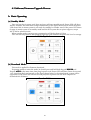
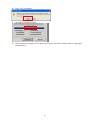
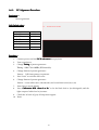
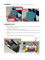
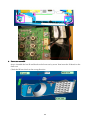
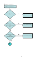
4.3 Software/Firmware Upgrade Process
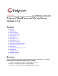
A. Basic Operating
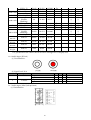
(a) Standby Mode:
Mode:
User can just plug in power cord, then projector will enter standby mode. Power LED will show
Red for around 1 sec, then show Orange continuously as the figure shown below. When the power
LED shows Red, it means system is not ready for standby. In another word, if the power LED shows
Orange, it means system is in standby mode and the DLP system has no power support, except
MCU and its related circuits.
When standby mode, system power consumption will be less than 0.5 Watt.
User can turn on projector after plugging in power cord whatever the power led is red or orange.
Standby Mode
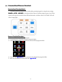
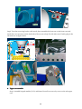
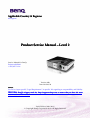
(b) Download Mode:
Mode:
This mode is applied for firmware download.
If operator wants to enter this mode, he should press and hold both keypad-POWER
POWER and
Keypad-AUTO
AUTO at the same time, then plug in power cord. Power LED will show Green for around
1 sec, then show Red continuously as the figure shown below. In download mode, system will be
supported by full power but will not turn on projector. Operator can use DLP composer to
download new firmware.
Download
Download Mode
48
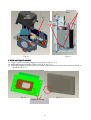
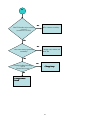
(c) Power On:
On:
User can press Keypad Power to turn on projector. User can also use IR remote controller and
RS-232 Command:<CR>*pow=on#<CR> to do this action. When system turning on, power LED
will flash Green as the figure shown below.
Power On
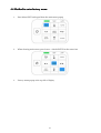
(d) Power Off:
Off:
If user wants to turn off projector, user can double click keypad Power, use IR remote controller,
or RS-232 Command:<CR>*pow=off#<CR>. Then, system will cool itself via fans for 3 seconds
(quick cooling) or 90 seconds (normal). During cooling, Power LED will flash Orange. After
cooling, system will return to standby mode and Power LED will become Orange as the figure
shown below.
Power Off
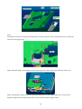
(e) EDID Download mode:
mode:
To relief PC/ HDMI EDID write protect function:
1. Press Power+
Power+Source on keypad then plug in power cord.
2. EDID can be downloaded to EEPROM by Q-EDID tools. PC1& PC2 share the same EEPROM.
EDID Download mode
49
B. Download MCU Code and Firmware
(a) Auto MCU Code Download
Download:(for LowLow-Power Standby)
Condition:
Condition:
Auto Detect, download by MCU itself.
Situation 1:MCU code is empty (The 1st time to plug in power cord)
Situation 2:MCU version update
System Action:
Action:
System needs around 2 sec to download MCU itself automatically.
Downloading
Downloading:
oading:Power LED will show Red and Lamp LED will show Green.
Download Fail:
Fail:Power LED will show Orange and Lamp LED will show Red.
Download Success:
Success:System will go back standby mode and Power LED will show Orange.
Notice:
Notice:
Do NOT interrupt power when downloading.
50
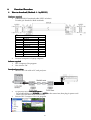
(b) Download Firmware
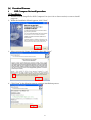
i.
DLP Composer lite install procedure
(1) Installation
1. Double click the Setup file for DLP Composer Lite (use 11.0 or above version) to start to install
program.
2. When the Installation Wizard appears, click “Next”.
3. Select to accept the License Agreement, than click “Next”
4. Click “Next” in the following steps to continue installation process.
51
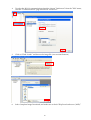
Note:
The default installation directory is:
C:\
C:\Program Files\
Files\DLP Composer
Composer Lite 11.0.1\
11.0.1\
If you want to install to a different directory (perhaps
alongside a prior release of DLP Composer™ Lite), click
the "Browse" button on the "Select Features" page.
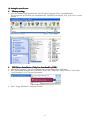
5. When finishing installation, click “Finish”, and then restart your computer to complete the
installation process.
52
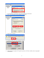
(2) Setting
Setting for your first use
Library setting:
1. Save the “FlashDeviceParameters.txt” into the DLP Composer Lite11.0 installed folder.
You can get the txt file from the installation file “DDP442X Download_Tool_Ver1.0.rar” or later
version.
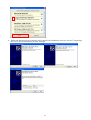
USB Driver Installation
Installation (Only for download by USB):
1. After DLP Composer™ Lite 11.0 is installed, it can auto detect your USB driver.
2. If PC still cannot recognize the USB device, choose the "Install DLP Device Drivers" icon under
"DLP Composer™ Lite" in your Start menu.
3. Select “Jungo WinDriver” and press “Install”.
53
4. Follow the message show in message, and complete the installation when you see the “Completing
the Device Driver Installation Wizard” message.
54
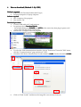
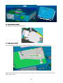
ii.
Download Procedure
How to download (Method -1 : by RS232)
Hardware required
1. Standard RS232 Download cable (SPEC as below)
D-sub 9-pin Female for Both terminals
P1
1
2
3
4
5
6
7
8
9
CASE
2.
WIRE ARRANGEMENT
COLOR
P2
BLACK
1
BROWN
3
RED
2
ORANGE
4
YELLOW
5
GREEN
6
BLUE
8
PURPLE
7
GRAY
9
DRAIN WIRE
CASE
Personal computer or laptop computer
Software required
1. DLP Composer Lite program
2. New version FW
Download procedure
1. Connect RS-232 cable to PC and projector
Let projector be in Download Mode :
- Press and hold keypad-POWER
POWER and AUTO at the same time, then plug in power cord.
- Power LED will show Red continuously.
3. Execute DLP Composer Lite 11.0 program
2.
55
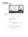
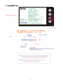
4.
To select the RS-232 communications interface, choose "Preferences" from the "Edit" menu,
click the "Communications" page and choose "Serial Port".
5.
Click on “Flash Loader” and browse the image file (new version firmware)
6.
Select Complete Image Download, and make sure to check “Skip Boot loader area (32KB)”
56
7.
8.
Press “Reset Bus” and check the status which should show “Bus Reset”
Press “Start Download” to begin update new firmware.
9.
Press “Yes” to continue.
10. Wait till composer lite notice download complete.
11. When download complete, LED signal on projector will show standby status (orange light
continuously).
57
How to download (Method(Method-2 : By USB)
Hardware required
1. Standard USB Download cable(mini B type)
2. Personal computer or laptop computer
Software required
1. DLP Composer Lite program
2. New version FW
Download procedure
1. Connect USB cable to PC and projector
2. Let projector be in Download Mode:
- Press and hold keypad-POWER
POWER and AUTO at the same time, then plug in power cord.
- Power LED will show Red continuously.
3. Execute DLP Composer Lite 11.0 program
4.
5.
To select the USB communications interface, choose "Preferences" from the "Edit" menu,
click the "Communications" page and choose "USB".
Check the USB Device Identification. Vendor should be 0x451.
0x451 Product should be 0x2000.
6.
Click on “Flash Loader” and browse the image file (new version firmware)
58
7.
Select Complete Image Download, and make sure to check “Skip Boot loader area (32KB)”
8.
9.
Press “Reset Bus” and check the status which should show “Bus Reset”
Press “Start Download” to begin update new firmware.
59
10. Press “Yes” to continue.
11. Wait till Download complete.
12. When download complete, LED signal on projector will show standby status (orange light
continuously).
60
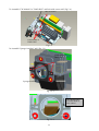
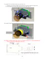
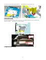
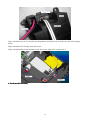
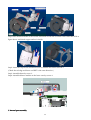
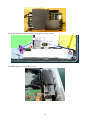
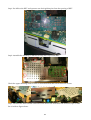
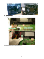
(c) Extension Board Firmware Download :
Extension Board Download Mode:
Mode:
Extension board download can be achieved by pressing keypad or using factory setting.
POWER + AUTO + SOURCE (as the figure below shown) and then plug in power cord. Then,
system will input the extension board download mode. And then Power and TEMP LED will
show Orange light.
Firmware Download Procedure:
Procedure:
1. Connect USB cable to PC and projector
2. Let projector be in Extension board Download Mode.
3. Launch “FlashUpgrader” program from the download program folder.
4. Cover the old appcode.bin
appcode.bin file by new one in the download program folder.
5. Select the download file and choose the “appcode.inf
appcode.inf”
appcode.inf
61
6. Press the button ”Flash” and start to download.
7. The extension board is downloading
62
8. Download success.
Notice:
Notice:
1. Do NOT interrupt power when extension board is downloading.
2. When extension board download success, please plug out power cord and plug in power
cord to make sure that system is reset.
63
4.4 Method to enter factory menu
1.
Press Menu/EXIT on keypad than the main menu popup
2.
When showing main menu, press Source + Mode/ENTER at the same time
3.
Factory menu popup at the top-left of display
64
4.5 RSRS-232 connection
1. Below shows the illustration of connection between PC and Projector.
<CAUTION>
Make sure that your computer and projector are turned off before connection.
Power on the computer first, and then plug the power cord of the projector.
(It may cause Com port incorrect function, if you do not follow this instruction)
Adapters may be necessary depending on the PC connected to this projector. Please contact with
your dealer for further details.
2. Hardware connection
<Download cable 1>
P1
1
2
3
4
5
6
7
8
9
CASE
WIRE ARRANGEMENT
COLOR
P2
BLACK
1
BROWN
3
RED
2
ORANGE
4
YELLOW
5
GREEN
6
BLUE
8
PURPLE
7
GRAY
9
DRAIN WIRE
CASE
<pin assignment for this two end>
Pin
1
3
5
7
9
Description
NC
TXD
GND
RTS
NC
Pin
2
4
6
8
Description
RXD
NC
NC
CTS
65
1
2
6
3
7
4
8
5
9
Interface Settings
RS-232 protocol
Baud Rate
Data Length
Parity Check
Stop Bit
Flow Control
115200 bps (default)
Changeable settings in User OSD
(2400/4800/9600/14400/19200/38400/57600/115200)
8 bit
None
1 bit
None
Software specification
1. When input cmd fail, e.g. correct input is “*pow=?#” but input “*po=?#”, or input “*mute=on#”
while projector is already mute, it will show “*Illegal format#”.
2. When input cmd but projector has no such function item, e.g. input “*sour=RGB2#” but
projector has no RGB2 connector, it will show “*Unsupported item#”.
3. When cmd and function are both workable, but it’s not under the status which cmd can be
executed, e.g. input “*asp=4:3#” while not connecting source, it will show “*Block item#”.
4. When input “query” cmd (with “?”), e.g. input “*sour=?#”, it will echo the same input strings
with some value.
5. Press “Enter” key after” >”, it should be no echo and skip to the next row.
6. Press “Space” and “Enter” key after” >”, it will echo”*Illegal format#”
Command Category
Refer to Appendix 2
66
4.6 Adjustment / Alignment Procedure
Content
4.6.1. Color Wheel Delay Alignment
4.6.2. Overfill adjustment
4.6.3. PC Alignment Procedure
67
4.6.1.
4.6.1. Color Wheel Delay Alignment
Procedure:
1. Enter Factory Mode
2. Enter Block 1
3. Change CW Delay by adjusting the following gray pattern to smooth
32 Gray pattern
68
4.6.2.
4.6.2. Overfill adjustment
1. “Full White Pattern” is suggested for this alignment.
2. Adjust 2 LP-alignment Screws (upper side / lower front side of Optical Engine) behind Color
Wheel.
3. Alignment Criteria is to adjust these 2 screws until “No Dark Edges” and “No Shadows” can be
observed in image.
69
1.6.3.
PC Alignment Procedure
Equipment:
Equipment:
-
Pattern generator
OSD Default value:
value:
Item
Cal R Offset
Cal G Offset
Cal B Offset
Cal R Gain
Cal G Gain
Cal B Gain
Value
512
512
512
1024
1024
1024
Procedure:
Procedure:
1.
Connect power cord and PC D-sub source into projector.
2.
Turn on projector.
3.
Change Timing of pattern generator:
Timing: 1024*768 @60Hz (XGA models)
4.
Change Pattern of pattern generator:
Pattern: Full frame pattern, ex.pattern1
5.
Press “Auto” to catch the full screen
6.
Change Pattern of pattern generator:
Pattern: A near white color (240,240,240) and a near black color(16,16,16)
7.
Enter Factory mode, block 3
8.
Press “Calibration
Calibration RGB <Press
<Press L or R>”
R> to let the black level to just distinguish, and the
light output of white level to just max.
9.
Check the 32 levels of gray. All steps must appear.
10. Done
70
5. Level 2 Circuit Board and Standard Parts Replacement
5.1 Product Exploded View
Module 1 – Total Exploded View
71
72
Module 2 – ASSY UPPER CASE
73
Module 3 – ASSY LOWER CASE
74
Module 4 – ASSY FRONT CASE
75
5.2 Product Disassembly / Assembly
76
77
78
79
5.3 Module Assembly
Assembly Key Point - Optical Engine
1. Light Pipe Module assembly and overfill alignment
1.1 Assembly LP Module to HSG DMD
i.
ii.
iii.
Assembly “Clip LP” and lock with screw well (Fig. 1-2).
Press CLIP of RE_BKT_LP first, and then push it into the hole (Fig. 1-3).
Placed LP Module on LP datum of “DMD HSG” and adjustment screw well, shown(Fig. 1-4).
iv.
v.
Assembly “Baffle LP” first (Fig. 1-5) & push “Baffle LP” to hook DMD HSG(Fig. 1-6),
When Lock the screw of Baffle LP ,the hand must push the left corner of Baffle LP before (Fig.
1-7),.
vi.
vii.
Lock the screw of Baffle LP well then release the hand (Fig. 1-8),
Assembly two Overfill adjustment screws (M2, 8L) to HSG DMD (Fig. 1-1).
** Adjustment criteria refer to below item 1.2
1.2 Overfill Adjustment @ LP Module
Overfill Adjustment Criteria:
i.
ii.
Pre-assembly 2 adjusting screws.
Alignment Sequence:
a.
To adjust “Horizontal Adjustment Screw” firstly, and then “Vertical Adjustment Screw”.
(Based on production line condition, OE could change the sequence)
1.3 For Overfill Re-adjustment:
a.
Loosen two adjustment screws
b.
Follow adjustment steps shown in Item 1.2-ii.
Overfill Vertical
Adjustment Screw
M2, 8L
Overfill Horizontal
Adjustment Screw
M2, 8L
Fig. 1-1
80
Clip LP
M2*3L screw
Fig. 1-2
1. Press down the
Clip
2. Insert the
LP Module
Fig. 1-3
81
LP Datum of DMD
HSG
Overfill adjustment screws
Fig. 1-4
1. Place Clips on
BKT surface
2. Push Baffle LP to
hook DMD HSG
Fig. 1-5
Fig. 1-6
Push on the left corner until lock
the screw well
Lock the screw well
Fig. 1-7
Fig. 1-8
82
2. Assembly FM:
2.1 Place FM on “HSG DMD” surface(Fig. 2-1) and use “Clip FM” to fix FM(Fig. 2-2).
Push Clip FM
to HSG
Touch the side
surface
Fig. 2-1
Fig. 2-2
3. Assembly HSG ILL Module:
3.1 CM Assembly
i.
ii.
iii.
iv.
v.
Insert “Clip CM Side” first, and then place “Clip Front CM” to fixed-shaft of ILL SUB before
locking screw (Fig. 3-1, Fig. 3-2).
Assemble Mylar SUB HSG to HSG ILL well (Fig. 3-3).
Assemble CM to HSG ILL and to make CM contact three datum on the HSG ILL well (Fig.
3-3).
Assemble” MYLAR CM ” to the CMD firstly, “CLIP TOP CM”(with forceps) to the “HSG ILL”
(Fig. 3-4,).
To check and make sure “CLIP of CM” hooks the HSG ILL very Well (Fig. 3-5).
Clip CM Side
Fixed shafts of
ILL SUB
Fig. 3-1
Fig. 3-2
83
M2*3.5L Screw
Datum3
Datum1
Datum2
Clip UP CM
Fig. 3-3
MYLAR CM
Fig. 3-4
Fig. 3-5
4. AL, HSG ILL and HSG DMD Assembly:
4.1 Placed “AL” on the “HSG DMD”. The “raised surface” of “AL” shall toward “DMD direction” (Fig.
4-1).
4.2 To assemble ”HSG ILL SUB Module” with “HSG DMD” and cover over on “AL” and the then lock
with screws(Fig. 4-2).
84
Fixed shafts&
holes
AL
M2
DMD Direction
Fig. 4-1
Fig. 4-2
5. DMD and Chip B/D Module:
5.1. Judge Chip B/D and DMD alignment keying first (Fig. 5-1, 5-2).
5.2. Alight keying and Assemble DMD to Chip B/D (Fig. 5-3).
5.3. Push DMD slightly and use screwdriver rotate clockwise button to lock (close notation) DMD on
Chip B/D (Fig. 5-4).
Fig. 5-1
Fig. 5-2
Alignment keying
85
Open notation
Button
Close notation
Fig. 5-3
Fig. 5-4
6. Assembly
Assembly Optical ENG
6.1 Assemble “BKT Link Lamp & CW shield” on “DMD HSG” and then lock with screws well (Fig.
6-1)..
BKT Link Lamp
Shield CW
M3*5L Screw
Fig. 6-1
7. Assembly OP ENG
7.1 Assemble “Baffle DMD” to “HSG DMD” (Fig.7-1).
7.2 Assemble “Sponge DMD” to “HSG DMD” (Fig.7-1).
7.3 Assemble Chip B/D Module to “HSG DMD” (Fig. 7-2).
86
Alignment keying
Sponge DMD
Baffle DMD
Fig.7-1
Fixed shafts of
DMD HSG
Fig.7-2-1
87
Fixed holes of DMD
Fig.7-2
7.4 Assemble Thermal Pad & Gasket Hest-sink then place contact DMD (Fig. 7-3, 7-3-1~2).
1.>Press center of Heatsink before assemble spring screw.
then keeps press until spring screw assembly finish.
2.>Pre-fastening Sequence: [ 1 ] - [ 2 ] - [ 3 ] - [ 4 ].
3.>Fastening Sequence: [ 2 ] - [ 1 ] - [ 4 ] - [ 3 ].
4.>Screw Torque must be confirmed to be 6 kg-cm.
Press Heatsink when
assemble spring screw
Spring Screw
○
3
○
1
○
4
○
2
Fig. 7-3
Fig. 7-3-1
EMI Gasket
Fig. 7-3-2
88
7.5 Assemble “CW Module” to “DMD HSG” and lock with screws well (Fig.7-4).
M3*4L Screw
Fixed shafts of
DMD HSG
Fig.7-4
7.6 Assemble “Sponge Antidust” well (Fig. 7-5).
Fixed shafts of
DMD HSG
Sponge Antidust
Fig.7-5-1
The sponge can’t
cover the hole of
HSG DMD
Fig.7-5-2
89
7.7 Assemble “PL Lens” and lock with screws well (Fig. 7-6).
i. Assemble Lens and the Assembly direction must be horizontal, and do not impact CM.
ii. Pre-fastening Screws firstly and Fastening the Screws well. (Fig. 7-6)
Screw*3
Fig.7-6
7.8 Assemble “Ring Zoom” and lock with screws well (Fig. 7-7).
M2*3L Screw
M2*3L Screw
Fig. 7-7
Note: When assembling “Ring Zoom”, please set screwdriver torque at 1.2-1.7kg-cm and make sure
there is a gap between “Ring Zoom” and screws.
Ring Zoom
Screw
Lens
Keep a gap between Ring Zoom and screw
90
Screw M2*3.5L
Make sure there is a gap between
Ring Zoom and screws
7.9 Assemble “Ring Focus” well (Fig. 7-8).
Fig. 7-8
91
5.4 Module Assembly
Assembly Key Point - Mechanical
Mechanical Assembly Concerns
1. Lower case module assembly
2. OM module assembly
3. Lamp frame module assembly
4. Nozzle module assembly
5. Internal parts assembly
6. Rear case assembly
7. Right and Left case assembly
8. Front case assembly
9. Upper case assembly
10. Lamp module assembly
11. Lamp door assembly
1. Lower case module assembly
The lower case module assembly processes are as follows,
1-1
Insert the rubber foot rear 、foot adjust rear on the lower case.
Assemble the front adjust foot module including foot adjust body、pad adjust、spring slider、button
push on the lower case, and the assembling method is as other models.
92
1.2 Insert the screws and assemble SHD LC 、MYLAR ENG LC on the lower case.
2. OM module assembly
Assemble OM module and clip cable on the lower case as figure shows by screws, and follow the
sequence 123. Add Gasket*2 on Optical Engine.
Gasket
Gasket
3. Lamp frame module assembly
93
Step1. Assemble wire of AC switch in the lamp frame and check wire is inside near the wall as figure
shows.
Step2. Assemble wire of lamp start with screw.
Step3. Assemble lamp frame module on the lower case with screw 1 and screw 2.
4. Nozzle module assembly
94
Step1.Place thermal breaker in the nozzles and check words side is outside. Next insert the SHD as
figure shows, and check copper surface is inside.
Step2. Insert the clip mount and mount seat to combine the blower and BKT.
(Check the red edge on blower and BKT is the same direction.)
Step3. Assemble them by screw. 3.
Step4. Assemble blower module on the lower case by screws 4.
5. Internal parts assembly
95
5-1 Assemble
Assemble power board on the lower case, and screw.
Step1. Plug the wire of thermal breaker in the connector.
Step2. Plug in the wire of AC switch, and check the wire. Don’t block the screw hole as figure shows.
Step3. Assemble the capacity cap on the big capacity.
5- 2
Assemble ballast board fixed with 2 holders on the lower case by screw. Plug in the wire of HV
and wire of MB to ballast.
Check the wire arrangement must follow figure shows.
Step1. Assemble the holder 2 first, then insert the Mylar ballast, and at last assemble the holder 1 and
2 wires.
96
Step2. Assemble the ballast module on the lower case by screws.
Fix Ballast Mylar wire to MB by screw*1
97
Step3. Insert the wire of HV and wire of lamp start.
Check the both wires should under the ballast board, and wire of lamp start should be arrangement
as figure shows.
5-3 BKT of MB assembly
Step1. Assemble axial fan with 5-pin wire on lower case before assemble main board bracket.
Assemble the left leg of BKT behind AC socket and align the right leg with rib on the lower case.
98
Step2. Assemble the BKT on the lower case sequentially by screw and screw ground connection.
Check the wire of AC socket must through the gap as figure shows. Add Gasket*2 on BKT.
Gasket
5-4 MB assembly
Note: ASSY MB & Extension BD~
99
Note1 part list
Note 2
Note 3
Note 4 : Add Spring on HDMI connector
100
Step1. Put MB on the BKT and operator can check golden pins from the opening of BKT.
Step2. Assemble the shielding of MB and screws,, and a clip on the BKT.
Check the upper shielding need to cover on main board bracket before fasten the screws
Step3. Assemble the Inlet fan and outlet fan on the lower case. And check the direction, tape of inlet
fan is inside as figure shows.
101
5- 5
wires arrangement
Step1. Plug the wire of blower and wire of MB to ballast.
Step2. Plug in the wire of CW signal and wire of CW.
102
Step3. Plug in the wire of lamp fan and wire of power fan.
6. Rear case assemble
Step1. Assemble the assy sub rear case module on the lower case as figure shows.
Check two hooks are near the location as figure shows.
7. Right and Left case assembly
Step1. Right case assemble
Assemble the speaker on the assy sub right case by screws.
103
Step2. Plug in the speaker connector as figure shows and put the speaker wire as below. Then,
assemble the sub-right case on the lower case.
Step3. Assemble the left case on the lower case, and check the wire of inlet fan arranged as figure
shows.
104
8. Front case assemble
Step1. Assemble the lens IR and hook on the front case by screw. Next insert the IR board on the
front case.
Check the IR lens: don’t set the wrong direction.
105
Step2. Turn the zoom ring back to wide mode, then assemble the front case on the lower case and
check there are structures on the both side of front case to help fix with side cases. Finally, plug in the
IR connector as figure shows.
9. Upper case assemble
Step1. Assemble keypad module (P+R) and fasten Zoom/Focus cover by screw on the sub upper
case.
106
Note:
Assemble Zoom/Focus cover by the steps below. Need to push the cover until hook on cover touch the
side wall of the upper case.
Step2. Assemble upper case module on the whole projector, check three pins will insert front case.
Step3. Assemble the upper case on the projector and screw on the lamp frame and 5 screws at the
bottom as figure shows; lamp frame and 5 screws at the bottom as figure shows.
107
10. Lamp module assemble
Assemble the lamp module and screw it.
11. Lamp door assemble
Step1. Assemble the Mylar of anti-explosion along the edges of upper case as figure shows.
Step2. Insert the lamp door into the 3 hooks on the upper case and fix it by screw on the left case as
below figure shows.
108
109
5.5 Block Diagram
Figure 1 Main board & Input board Block Diagram
110
5.6 Trouble shooting
Chapter 1 System Analysis
Chapter 2 Optical & Optical Engine Trouble Shooting Guide
Chapter 3 Power Supply Trouble Shooting Guide
Chapter 4 LED Messages Definition
Chapter 5 Error Count Messages Definition
111
Chapter 1 - System Analysis
Keypad LED OK?
:
NO
Step
1. Check Lamp Door
2. Check Connection between Power BD and Main BD
3. Check Power Board and Interlock
4. Check Main Board
NO
Step
1. Check Lampen wire , Lamp wire and Ballast wire
2. Check C/W and wire connection
3. Check Main board
4. Check Lamp
5. Check Ballast
YES
Step
1. Check Input Cable
2. Check OSD Source set up
3. Check Main board
YES
Step
1. Check OSD Lamp Hours
2. Check Lamp Door
3. Check Lamp still light or not?
4. Check Fan still spin or not?
5. Check Thermal status
YES
Step
1. Check Remote module battery
2. Check Remote module
3. Check IR wire between Main board and IR board
4. Check IR Reciver on IR board
YES
Step
1. Check the connection between
Main BD and Chip BD
2. Check the connection between
OP engine and DMD Chip
3. Check Chip board
4. Check Main board
YES
Lamp On?
:
YES
:
No Signal?
NO
Power Auto Turn Off?
:
NO
IR Remote Control NG?
:
:
NO
Pixel Fail?
112
Chapter 2 Optical & Optical Engine Trouble Shooting Guide
No.
1
Item
Brightness
Trouble Shooting Guide
2
Uniformity
1. Change lamp
FOFO Contrast
1. Check ADC calibration
2. Check user’s menu brightness & contrast are default
3. Clean DMD
3
1. Change lamp
4. Clean PL
5. Check ILL stop assy
4
ANSI Contrast
1. Clean PL
2. Clean DMD
3. Change PL
5
Color
1. Check color wheel delay
2. Check CW 50% point. Replace CW if necessary
6
Color Uniformity
1. Change lamp
1. Refer to Item#2-1 (attached below)
7
Blue Edge
2. Change CM
3. Change SUB HSG
1. Refer to Item#2-1(attached below)
8
Blue/Purple Border
9
Focus
1. Change Projection Lens
2. Check parallel between PL datum and DMD
10
Dust
Clean DMD
11
Horizontal/Vertical
Strips
12
Pixel Fail
2. Change CM
3. Change SUB HSG
1. Check connector between chip BD and Main BD
2. Re-install DMD with chip BD
3. Check if any pin of C-Spring is missing, damaged or dirty
4. Change new Chip BD/C-Spring
5. Change new DMD
Change new DMD
2-1. “Blue Edge” Trouble Shooting:
I. Re-adjust “Overfill” first.
For Overfill Re-adjustment:
i. Those 2 Adjustment Screws must be released for around 2 mm first.
ii. Alignment Sequence:
c.
d.
To adjust “Horizontal Adjustment Screw” firstly, then “Vertical Adjustment Screw”.
Refer to Figure 2-1..
113
(2) Overfill Vertical
Adjustment Screw
(1) Overfill Horizontal
Adjustment Screw
Fig. 2-1
II. Re-assemble LP module—include LP, LP Baffle, LP clip.
114
Chapter 3 Power Supply Trouble Shooting Guide
1. Introduction
This document is prepared to be a guide to repair trouble sets, some problems happen more
frequently are taken as example in it.
2. Problems
Problems
(a) no power
No power
Check power BD
Is CN701 pin7 =3v?
Yes
Change main BD
No
Yes
Change power BD
Is door SW press
down?
No
Check lamp door
115
(b)lamp
can not turned on
(b)
Lamp can not turned on
Has lamp wire connect
correct?
(Between Ballast and lamp)
No
Wire connect certainty
Yes
has power wire connect
correct?
(Between PWR BD and
ballast)
No
Wire connect certainty
Yes
Has enable wire connect
correct?
(Main BD to ballast)
No
Wire connect certainty
Yes
A
116
A
Has TH breaker wire connect
correct?
(connect to CN702)
No
Wire connect certainty
Yes
No
Change color wheel and
Has color wheel operation
normally?
Main BD
Yes
If change ballast bd, lamp
can be
Turned on or not?
No
Change lamp
Yes
Change ballast
board
117
Chapter 4 - LED Messages Definition
LED Messages Definition
Power Temp Lamp
Status
System Messages
Stand-by
Powering up
Normal operation
Normal power-down cooling
Download
CW start fail
Scaler shutdown fail(data abord)
BurnBurn-In Messages
Burn-in ON
Burn-in OFF
Lamp Error Messages
Lamp1 error in normal operation
Lamp is not lit up
Thermal Error Messages
Fan 1 error (the actual fan speed is ±25% outside the desired speed)
Fan 2 error (the actual fan speed is ±25% outside the desired speed)
Fan 3 error (the actual fan speed is ±25% outside the desired speed)
Fan 4 error (the actual fan speed is ±25% outside the desired speed)
Temperature 1 error (over limited temperature)
Thermal Sensor 1 open error
Thermal Sensor 1 short error
Thermal IC #1 I2C Connection error
118
Chapter 5 - Error Count Messages Definition
Error Count
Definition
Specification
Lamp Fail
Lamp Off
Detect LampLit NG
Fan 1 Speed Error
Fan 2 Speed Error
Lamp Fan Speed Error
Power Fan Speed Error
Speed Over ± 20%
Speed Over ± 20%
Fan 3 Speed Error
Fan 4 Speed Error
Sensor 1 Open Error
Sensor 1 Short Error
Blower Fan Speed Error
DMD Fan(Inlet Fan) Speed Error
Main Board Sensor Error
Main Board Sensor Error
Speed Over ± 20%
Speed Over ± 20%
Detect Sensor 1
Detect Sensor 1
Temperature 1 Error
FanIC 1 I2C Error
Color Wheel Error
Abnormal Power down
Over temperature
N/A
Color wheel operating Error
System abnormal power down
>53℃
N/A
119
Appendix 1 – Screw List / Torque
Model name : MX662
Torque
Q’T
Where use
Coatin Y
Length
gth
(kgf--cm)
Type Head Len
(kgf
g
MAC
M2.5 1 8F.00430.6R0
PH
6
NI
2
4~5 Right case & Speaker(2*)
H
Lamp frame & Connector(1*)
8F.VG564.8R
1
TAP PH
8
NI
5
6~7 Lower case & Blower BKT(2*)
0
Lower case & Lamp frame(2*)
Lower case & PWR BD(4*)
8F.VG524.6R
2
TAP PH
6
NI
5
6~7 Upper case & Zoom/Focus
0
Cover(1*)
Hook & Front case(1*)
3 8F.VA564.6R0 TAP PH
6
NI
2
6~7
Lower case & Lamp frame(1*)
M3.0
OM & Lower case(3*)
Upper case & Lower case(5*)
4 8F.VA564.8R0 TAP PH
8
NI
11
6~7
Upper case & Lamp frame(1*)
Lower case & Ballast holder(2*)
SHD MB & BKT MB(6*)
MAC
5 8F.1D224.5R0
PH
5
NI
11 5.5~6.5 Blower BKT & Nozzle(1*)
H
MB & Extension board (4*)
MAC
6 8F.00521.001
PH
8
B-NI 1 5.5~6.5 Lamp door & Left case(1*)
H
5.5~6.5 AC Wire & BKT MB(1*)
TAPTI
M4.0 1 8F.1D526.6R0 MACH
6
NI
4
LE
5.5~6.5 Lower case for ceiling (3*)
#4STAN
#4-4
1 8F.00649.120 MACH
8
NI
8 4.5~5.5 Rear case & D-SUB(8*)
0
D
STAN
17 Brass 2 5.5~6.5 MB & Extension board (2*)
M3 1 8F.00642.170 MACH
D
Screw Type: 10 types
No
Screw P/N
.
Description
Screw quantity: 51
120
Model Name :MX662
:MX662 (OM)
Type
P/N
Description
Type Head
8F.8A752.3R0
M2
8F.1A752.8R0
DMD
HSG
8F.00603.4R0
8F.1A554.4R0
M3
8F.1A554.5R0
6E.1P501.001
SUB
HSG
MODU
LE
CW
MODU
LE
M2
M2
MA
CH
8F.1A752.3R0
MA
CH
M2
Lamp
Modu
le
8F.1A752.3R0
8F.1A554.6R0
M3
RH
PH
8F.1A552.4R0
8F.00345.5R6.
8F.2R754.6R0
8F.VA564.6R0
8F.VG564.8R0
M2
8F.1A752.3R0
M3
8F.JA754.4R0
Lens
Where use
3.0
3.5
3.0
4.0
MA
FPH
CH
MA
FPH
CH
M
AC
H
PH
M
AC PAN
H
M
AC HEX
H
TA
PH
P
TA
PH
P
MA
RH
CH
MA
FPH
CH
Unit
Q’t
y
Lengt Surfa
(kgf--cm)
(kgf
h
ce
SHIELD CW VS. BKT
LINK LAM
B-NI 2.5+/-0.5
BAFFLE LP VS. HSG DMD
CLIP LP VS. HSG DMD
MA
PH
8.0 B-NI 2.5+/-0.5
LP Adjustment
CH
MA
ILL SUB HSG VS. DMD
RH
4 B-NI 2.0+/-0.5
CH
HSG
MA
CW MODULE VS. HSG
PAN 4.0
NI 4.0+/-0.5
CH
DMD
MA
BKT LINK LAMP VS. HSG
PAN 5.0
NI 4.0+/-0.5
CH
DMD
MA
PH 13.85 NI 6.0+/-0.5 H-Sink VS. HSG DMD
CH
8F.FA322.3R5
8F.8A752.3R0
M2.5
MA
FPH
CH
Torque
3.0
5.6
3
B-NI 2.2+/-0.5
Clip CM Front VS Sub
HSG
CW Sensor BD VS. BKT
CW
B-NI 2.5+/-0.5
CW CVR VS. BKT CW
2.5+/-0.5 CW CVR VS. BKT CW
CVR Anti Dust VS. CVR
B-NI 1.5+/-0.5
CW
NI 3.5+/-0.5
BNI
2.5+/-0.
5
1
1
1
3
2
2
2
2
1
1
2
2
4
4
1
1
1
2
1
1
1
1
1
CW VS. BKT CW
3
3
FIN VS. HLD Lamp
Clip Lamp UP VS. HLD
Lamp
Clip Lamp Down VS.
HLD Lamp
Clip FG VS. HLD Lamp
CVR Lamp VS. HLD
Lamp
1
2
2
8
1
2
6
NI
5+/-0.5
BKT Link Lamp VS. HLD
Lamp
1
1
6
BNI
5+/-0.5
Plate Lamp VS. HLD
Lamp
1
1
6
NI
5+/-0.5
1
1
8
NI
5+/-0.5
1
1
Plate Lamp VS.
Connector
Lamp Wire VS.
Connector
3.5
B-NI 2.2+/-0.5
Ring Zoom VS. Lens
2
2
4.0
B-NI 3.0+/-0.5
Frame VS. HSG DMD
3
3
SUM =
121
39
Appendix 2 - Code List: IR / RS232 / DDC Data
Remote Control Code:
1. IR Code
Key
1
Function
Description
Wireless
2
Power
3
Freeze
4
Source
5
Page Up
6
Page Down
7
Eco Blank
8
Auto
9
10
Keystone +
Keystone -
11
Up
12
Down
13
Left
14
Right
15
Menu/Exit
16
Mode
17
Contrast
18
19
20
SWAP
Aspect
Mute
0x00
Suppor
t
No
0x02
Yes
0x03
Yes
0x04
Yes
0x05
Yes
0x06
Yes
0x07
Yes
0x08
Yes
0x09
0x0A
No
No
0x0B
Yes
0x0C
Yes
0x0D
Yes
0x0E
Yes
0x0F
Yes
0x10
Yes
0x11
No
0x12
0x13
0x14
No
Yes
Yes
Code
This button will on/off the
projector.
This button will freeze/ unfreeze
the image.
This button will show available
source options.
By pressing “Page Up” button,
could enable Page Up function.
By pressing “Page Down” button,
could enable Page Down
function.
This button will turn projector
into/out of blank mode.
This button will automatically
adjust projector’s picture quality.
When there is no OSD on screen,
this button will correct optical
keystone in negative direction.
When there is OSD menu on
screen, this button will move the
chooser item to the upper one.
When there is no OSD on screen,
this button will correct optical
keystone in positive direction.
When there is OSD menu on the
screen, this button will move the
chooser item to the next one.
When there is OSD menu on
screen, this button will move the
chooser item to the left one.
This button will move the
chooser item to the right one.
This button will turn on/off
OSD menu.
When there is no OSD menu on
the screen, the button will
change picture mode.
When there is OSD menu on the
screen, this button will excite the
item chooser.
Displays the CONTRAST setting
bar.
Select the display aspect ratios.
Mutes the built-in speaker.
122
ID and Protocol
Frequency
Protocol
38 KHz
NEC Format
Custom
Code
0x0030
21
Enter/OK
22
Brightness
23
24
25
26
Wireless
channel
Digital Zoom
+
Digital Zoom
Audio
27
PIP
28
29
30
POP
PAP
Capture
31
S-video
32
Q?
33
34
35
36
Timer on
38
Timer Setup
Scroll Up
(iPhone)
Scroll Down
(iPhone)
OK
(iPhone)
40
41
This button will show
unsupported logo.
This button will show
unsupported logo.
Turns the PIP window on or off
and makes related adjustments.
Displays the S-VIDEO source
selection.
Starts the INFORMATION
function.
Play/pause
(iPhone)
Next
(iPhone)
Prev.
(iPhone)
Menu/Back
(iPhone)
37
39
Enter key for OSD menu.
Displays the BRIGHTNESS
setting bar.
42
Smart Eco
43
44
45
46
47
48
49
50
51
52
1
2
3
4
5
6
7
8
9
RGBHV
53
RGB-PC1
54
DVI-D
When the presentation timer is
off , this button will activate/
stop the timer.
When the presentation timer is
on , this button will restart,
continue or turn off the timer.
By pressing “Smart Eco” button,
could open “Quick Lamp Menu”
to select lamp mode.
Displays the PC source selection.
Displays the PC 1 source
selection.
Displays the DVI-D source
123
0x15
No
0x16
No
0x17
No
0x18
Yes
0x19
Yes
0x1A
No
0x1B
No
0x1C
0x1D
0x1E
No
No
No
0x1F
No
0x20
No
0x21
No
0x22
No
0x23
No
0x24
No
0x25
Yes
0x26
Yes
0x27
No
0x28
No
0x29
No
0x30
Yes
0x31
0x32
0x33
0x34
0x35
0x36
0x37
0x38
0x39
0x40
No
No
No
No
No
No
No
No
No
No
0x41
No
0x42
No
55
DVI-A
56
DVI-I
57
RGB-PC2
58
Network
Display
59
USB Display
60
USB Reader
61
62
Power Off
Power On
63
Comp2
64
Comp1
65
CVBS-1
66
CVBS-2
67
S-video2
68
HDMI
69
HDMI2
70
GAMMA
COLOR
TEMP
USB
SETTING
USB Up
USB Down
USB Left
USB Right
USB Select
USB Return
ANA
04:03
LB
WIDE
REAL
MEMORY1
MEMORY2
MEMORY3
Default
COLOR
TINT
ACTIVE
71
72
73
74
75
76
77
78
79
80
81
82
83
84
85
86
87
88
89
90
91
IRIS
92
Brilliant
selection.
Displays the DVI-A source
selection.
Displays the DVI-I source
selection.
Displays the PC 2 source
selection.
Displays the LAN source
selection.
Displays the mini USB source
selection.
Displays the USB disk source
selection via type A USB port.
Turns off the projector.
Turns on the projector.
Displays the COMPONENT 2
source selection.
Displays the COMPONENT 1
source selection.
Displays the CVBS-1 source
selection.
Displays the CVBS-2 source
selection.
Displays the S-Video 2 source
selection.
Displays the HDMI source
selection.
Displays the HDMI source
selection.
Selects the ANA aspect ratio.
Selects the 4:3 aspect ratio.
Selects the LB aspect ratio.
Selects the WIDE aspect ratio.
Selects the REAL aspect ratio.
Select the User memory settings.
Select the User memory settings.
Select the User memory settings.
Displays the COLOR setting bar.
Displays the TINT setting bar.
Displays the setting bar for the
adjustment of the motorised
aperture lens IRIS.
124
0x43
No
0x44
No
0x45
No
0x46
No
0x47
No
0x48
No
0x4E
Ox4F
No
No
Ox50
No
0x51
No
0x52
No
0x53
No
0x54
No
0x58
No
0x59
No
0x5E
No
0x5F
No
0x60
No
0x61
0x62
0x63
0x64
0x65
0x66
0x70
0x71
0x72
0x73
0x74
0x75
0x76
0x77
0x78
0x79
0x7A
0x7B
No
No
No
No
No
No
No
No
No
No
No
No
No
No
No
No
No
No
0x7C
No
0x7D
No
93
94
95
96
Color
SHARP
OVERSCAN
Memory
Network
Setting
97
Volume +
98
Volume -
99
Back
100
101
Key Lock
PAN
102
Lens
103
104
105
106
107
108
109
110
111
112
Focus
Zoom
3D setting
V-keystone
H-keystone
PIP Size
PIP Position
Return
My Screen
Pattern
On(Split
screen)
Off(Split
screen)
Mic. Vol +
Mic. Vol SRS
CC
Teaching
Template
3D Menu
3D Sync
Invert
Mouse Left
Mouse Right
113
114
115
116
117
118
119
120
121
122
123
Select the User memory settings.
This button will magnify the
volume gradually.
This button will reduce the
volume gradually.
Goes back to previous OSD
menu,
exits and saves menu settings.
Displays the setting page for the
adjustment of the
motorised vertical Lens shift
value.
125
0x7E
0x7F
0x80
No
No
No
0x81
No
0x82
Yes
0x83
Yes
0x85
No
0x87
0x88
No
No
0x8A
No
0x8B
0x8C
0x8D
0x8E
0x8F
0x90
0x91
0x92
0x93
0x94
No
No
Yes
No
No
No
No
No
No
No
0x95
No
0x96
No
0x97
0x98
0x99
0x9A
No
No
No
No
0x9B
Yes
0x9C
No
0x9D
No
0x9E
0x9F
No
No
2. RSRS-232 Command Code
(Each input upper case and lower case character should be action) (Version 13)
Function
Type Operation
ASCII
Support
Write Power On
<CR>*pow=on#<CR>
Yes
Write Power off
<CR>*pow=off#<CR>
Yes
Power
Read Power Status
<CR>*pow=?#<CR>
Yes
Write COMPUTER1/YPbPr1
<CR>*sour=RGB#<CR>
Yes
Write COMPUTER 2/YPbPr2
<CR>*sour=RGB2#<CR>
Yes
Write Component1
<CR>*sour=ypbr#<CR>
No
Write Component2
<CR>*sour=ypbr2#<CR>
No
Write DVI-A
<CR>*sour=dviA#<CR>
No
Write DVI-D
<CR>*sour=dvid#<CR>
No
Write HDMI
<CR>*sour=hdmi#<CR>
Yes
Source
Write HDMI 2
<CR>*sour=hdmi2#<CR>
No
Selection
Write Composite
<CR>*sour=vid#<CR>
Yes
Write S-Video
<CR>*sour=svid#<CR>
Yes
Write Network
<CR>*sour=network#<CR>
No
Write USB Display
<CR>*sour=usbdisplay#<CR>
Yes
Write USB Reader
<CR>*sour=usbreader#<CR>
Yes
Read Current source
<CR>*sour=?#<CR>
Yes
Write Mute On
<CR>*mute=on#<CR>
Yes
Write Mute Off
<CR>*mute=off#<CR>
Yes
Read Mute Status
<CR>*mute=?#<CR>
Yes
Write Volume +
<CR>*vol=+#<CR>
Yes
Audio Control Write Volume <CR>*vol=-#<CR>
Yes
Read Volume Status
<CR>*vol=?#<CR>
Yes
Write Mic. Volume +
<CR>*micvol=+#<CR>
Yes
Write Mic. Volume <CR>*micvol=-#<CR>
Yes
Read Mic. Volume Status
<CR>*micvol=?#<CR>
Yes
Write Audio pass Through off
<CR>*audiosour=off#<CR>
Yes
Write Audio-Computer1
<CR>*audiosour=RGB#<CR>
Yes
Write Audio-Computer2
<CR>*audiosour=RGB2#<CR>
Yes
<CR>*audiosour=vid#<CR>
Yes
Audio source Write Audio-Video/S-Video
select
Write Audio-Component
<CR>*audiosour=ypbr#<CR>
No
Write Audio-HDMI
<CR>*audiosour=hdmi#<CR>
Yes
Write Audio-HDMI2
<CR>*audiosour=hdmi2#<CR>
No
Read Audio pass Status
<CR>*audiosour=?#<CR>
Yes
Write Dynamic
<CR>*appmod=dynamic#<CR>
Yes
Write Presentation
<CR>*appmod=preset#<CR>
Yes
Write sRGB
<CR>*appmod=srgb#<CR>
Yes
<CR>*appmod=bright#<CR>
Yes
Write Bright
<CR>*appmod=livingroom#<CR
No
Write Living Room
>
<CR>*appmod=game#<CR>
No
Picture Mode Write Game
Write Cinema
<CR>*appmod=cine#<CR>
Yes
Write Standard
<CR>*appmod=std#<CR>
No
Write User1
<CR>*appmod=user1#<CR>
Yes
Write User2
<CR>*appmod=user2#<CR>
Yes
Write User3
<CR>*appmod=user3#<CR>
No
Read Picture Mode
<CR>*appmod=?#<CR>
Yes
Write Contrast +
<CR>*con=+#<CR>
Yes
Write Contrast <CR>*con=-#<CR>
Yes
Picture
<CR>*con=?#<CR>
Yes
Picture Setting Read Contrast value
Write Brightness +
<CR>*bri=+#<CR>
Yes
Write Brightness <CR>*bri=-#<CR>
Yes
126
Operation
Settings
Read
Write
Write
Read
Write
Write
Read
Write
Write
Write
Write
Write
Read
Write
Write
Write
Write
Write
Write
Write
Write
Read
Write
Write
Write
Write
Write
Read
Write
Write
Write
Write
Write
Write
Read
Read
Write
Write
Read
Write
Write
Read
Write
Write
Read
Write
Write
Read
Write
Write
Read
Brightness value
<CR>*bri=?#<CR>
Color +
<CR>*color=+#<CR>
Color <CR>*color=-#<CR>
Color value
<CR>*color=?#<CR>
Sharpness +
<CR>*sharp=+#<CR>
Sharpness <CR>*sharp=-#<CR>
Sharpness value
<CR>*sharp=?#<CR>
Color Temperature-Warmer
<CR>*ct=warmer#<CR>
Color Temperature-Warm
<CR>*ct=warm#<CR>
Color Temperature-Normal
<CR>*ct=normal#<CR>
Color Temperature-Cool
<CR>*ct=cool#<CR>
Color Temperature-Cooler
<CR>*ct=cooler#<CR>
Color Temperature Status
<CR>*ct=?#<CR>
Aspect 4:3
<CR>*asp=4:3#<CR>
Aspect 16:9
<CR>*asp=16:9#<CR>
Aspect 16:10
<CR>*asp=16:10#<CR>
Aspect Auto
<CR>*asp=AUTO#<CR>
Aspect Real
<CR>*asp=REAL#<CR>
Aspect Letterbox
<CR>*asp=LBOX#<CR>
Aspect Wide
<CR>*asp=WIDE#<CR>
Aspect Anamorphic
<CR>*asp=ANAM#<CR>
Aspect Status
<CR>*asp=?#<CR>
Digital Zoom In
<CR>*zoomI#<CR>
Digital Zoom out
<CR>*zoomO#<CR>
Auto
<CR>*auto#<CR>
Brilliant color on
<CR>*BC=on#<CR>
Brilliant color off
<CR>*BC=off#<CR>
Brilliant color status
<CR>*BC=?#<CR>
Projector Position-Front Table <CR>*pp=FT#<CR>
Projector Position-Rear Table
<CR>*pp=RE#<CR>
Projector Position-Rear Ceiling <CR>*pp=RC#<CR>
Projector Position-Front Ceiling <CR>*pp=FC#<CR>
Quick auto search
<CR>*QAS=on#<CR>
Quick auto search
<CR>*QAS=off#<CR>
Quick auto search status
<CR>*QAS=?#<CR>
Projector Position Status
<CR>*pp=?#<CR>
Direct Power On-on
<CR>*directpower=on#<CR>
Direct Power On-off
<CR>*directpower=off#<CR>
Direct Power On-Status
<CR>*directpower=?#<CR>
Signal Power On-on
<CR>*autopower=on#<CR>
Signal Power On-off
<CR>*autopower=off#<CR>
Signal Power On-Status
<CR>*autopower=?#<CR>
Standby Settings-Network on
<CR>*standbynet=on#<CR>
Standby Settings-Network off
<CR>*standbynet=off#<CR>
Standby Settings-Network Status <CR>*standbynet=?#<CR>
Standby Settings-Microphone on <CR>*standbymic=on#<CR>
Standby Settings-Microphone off <CR>*standbymic=off#<CR>
Standby Settings-Microphone
<CR>*standbymic=?#<CR>
Status
Standby Settings-Monitor Out <CR>*standbymnt=on#<CR>
on
Standby Settings-Monitor Out <CR>*standbymnt=off#<CR>
off
Standby Settings-Monitor Out <CR>*standbymnt=?#<CR>
Status
127
Yes
Yes
Yes
Yes
Yes
Yes
Yes
No
Yes
Yes
Yes
No
Yes
Yes
Yes
Yes
Yes
Yes
No
No
No
Yes
Yes
Yes
Yes
Yes
Yes
Yes
Yes
Yes
Yes
Yes
Yes
Yes
Yes
Yes
Yes
Yes
Yes
Yes
Yes
Yes
No
No
No
No
No
No
Yes
Yes
Yes
Write
Write
Write
Write
Baud Rate
Write
Write
Write
Write
Read
Read
Read
Write
Write
Write
Write(
雙燈)
Lamp Control Write(
雙燈)
Write(
雙燈)
Write(
雙燈)
Read
Read
Write
Write
Read
Write
Write
Read
Write
Write
Write
Write
Write
Write
Write
Write
Miscellaneous Write
Write
Write
Write
Write
Write
Write
Read
Write
Write
Write
Read
Write
Write
Read
Write
2400
4800
9600
14400
19200
38400
57600
115200
Current Baud Rate
Lamp Hour
Lamp2 Hour
Normal mode
Eco mode
Smart Eco mode
<CR>*baud=2400#<CR>
<CR>*baud=4800#<CR>
<CR>*baud=9600#<CR>
<CR>*baud=14400#<CR>
<CR>*baud=19200#<CR>
<CR>*baud=38400#<CR>
<CR>*baud=57600#<CR>
<CR>*baud=115200#<CR>
<CR>*baud=?#<CR>
<CR>*ltim=?#<CR>
<CR>*ltim2=?#<CR>
<CR>*lampm=lnor#<CR>
<CR>*lampm=eco#<CR>
<CR>*lampm=seco#<CR>
Dual Brightest
<CR>* lampm =dualbr#<CR>
Dual Reliable
<CR>* lampm =dualre#<CR>
Single Alternative
<CR>* lampm =single#<CR>
Single Alternative Eco
<CR>* lampm =singleeco#<CR>
Lamp Mode Status
Model Name
Blank On
Blank Off
Blank Status
Freeze On
Freeze Off
Freeze Status
Menu On
Menu Off
Up
Down
Right
Left
Enter
3D Sync Off
3D Auto
3D Sync Top Bottom
3D Sync Frame Sequential
3D Frame packing
3D Side by side
3D inverter disable
3D inverter
3D Sync Status
Remote Receiver-front+rear
Remote Receiver-front
Remote Receiver-rear
Remote Receiver Status
Instant On-on
Instant On-off
Instant On Status
Lamp Saver Mode-on
<CR>*lampm=?#<CR>
<CR>*modelname=?#<CR>
<CR>*blank=on#<CR>
<CR>*blank=off#<CR>
<CR>*blank=?#<CR>
<CR>*freeze=on#<CR>
<CR>*freeze=off#<CR>
<CR>*freeze=?#<CR>
<CR>*menu=on#<CR>
<CR>*menu=off#<CR>
<CR>*up#<CR>
<CR>*down#<CR>
<CR>*right#<CR>
<CR>*left#<CR>
<CR>*enter#<CR>
<CR>*3d=off#<CR>
<CR>*3d=auto#<CR>
<CR>*3d=tb#<CR>
<CR>*3d=fs#<CR>
<CR>*3d=fp#<CR>
<CR>*3d=sbs#<CR>
<CR>*3d=da#<CR>
<CR>*3d=iv#<CR>
<CR>*3d=?#<CR>
<CR>*rr=fr#<CR>
<CR>*rr=f#<CR>
<CR>*rr=r#<CR>
<CR>*rr=?#<CR>
<CR>*ins=on#<CR>
<CR>*ins=off#<CR>
<CR>*ins=?#<CR>
<CR>*lpsaver=on#<CR>
128
Yes
Yes
Yes
Yes
Yes
Yes
Yes
Yes
Yes
Yes
No
Yes
Yes
Yes
No
No
No
No
Yes
Yes
Yes
Yes
Yes
Yes
Yes
Yes
Yes
Yes
Yes
Yes
Yes
Yes
Yes
Yes
Yes
Yes
Yes
Yes
Yes
Yes
Yes
Yes
Yes
Yes
Yes
Yes
Yes
Yes
Yes
No
Write
Read
Write
Write
Read
Write
Write
Read
Write
Write
Read
Read
Write
Write
Read
Lamp Saver Mode-off
Lamp Saver Mode Status
Projection Log In Code on
Projection Log In Code off
Projection Log In Code Status
Broadcasting on
Broadcasting off
Broadcasting Status
AMX Device Discovery-on
AMX Device Discovery-off
AMX Device Discovery Status
Mac Address
High Altitude mode on
High Altitude mode off
High Altitude mode status
129
<CR>*lpsaver=off#<CR>
<CR>*lpsaver=?#<CR>
<CR>*prjlogincode=on#<CR>
<CR>*prjlogincode=off#<CR>
<CR>*prjlogincode=?#<CR>
<CR>*broadcasting=on#<CR>
<CR>*broadcasting=off#<CR>
<CR>*broadcasting=?<CR>
<CR>*amxdd=on#<CR>
<CR>*amxdd=off#<CR>
<CR>*amxdd=?#<CR>
<CR>*macaddr=?#<CR>
<CR>*Highaltitude=on#<CR>
<CR>*Highaltitude=off#<CR>
<CR>*Highaltitude=?#<CR>
No
No
No
No
No
No
No
No
No
No
No
No
Yes
Yes
Yes
DDC
D-Sub
Analog EDID
00 FF FF FF FF FF FF 00
09 D1 02 2F 01 00 00 00
30 15 01 03 0E 00 00 78
0A AC D9 A1 5B 56 92 25
13 4F 5B BF EF 80 61 C0
81 80 95 00 81 C0 A9 40
45 7C 61 7C 81 3C 64 19
00 40 41 00 26 30 18 88
36 00 00 00 00 00 00 18
00 00 00 FD 00 17 78 1F
66 11 00 0A 20 20 20 20
20 20 00 00 00 FE 00 42
45 4E 51 0A 20 20 20 20
20 20 20 20 00 00 00 FC
00 42 65 6E 51 20 50 4A
0A 20 20 20 20 20 00 22
130
HDMI
Digital EDID
00 FF FF FF FF FF FF 00
09 D1 02 2F 01 00 00 00
30 15 01 03 80 00 00 78
0A AC D9 A1 5B 56 92 25
13 4F 5B BF EF 80 61 C0
81 80 95 00 81 C0 A9 40
81 3C 45 7C 61 7C 64 19
00 40 41 00 26 30 18 88
36 00 00 00 00 00 00 18
00 00 00 FD 00 17 78 1F
66 11 00 0A 20 20 20 20
20 20 00 00 00 FE 00 42
45 4E 51 0A 20 20 20 20
20 20 20 20 00 00 00 FC
00 42 65 6E 51 20 50 4A
0A 20 20 20 20 20 01 AF
02 03 29 71 4F 15 06 1F
90 03 04 05 11 13 14 02
12 20 21 22 23 09 07 07
83 01 00 00 6C 03 0C 00
10 00 18 2D 20 A0 02 01
41 02 3A 80 18 71 38 2D
40 58 2C 45 00 00 00 00
00 00 1E 01 1D 80 18 71
1C 16 20 58 2C 25 00 00
00 00 00 00 9E 01 1D 80
D0 72 1C 16 20 10 2C 25
80 00 00 00 00 00 9E 01
1D 00 BC 52 D0 1A 20 B8
28 55 40 00 00 00 00 00
1E 00 00 00 00 00 00 00
00 00 00 00 00 00 00 F0
131
Appendix 3 – Ceiling Mount Drawing
M4,
max screw length (L),
L=ceiling arm thickness+8mm
132