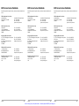
1
Artisan Technology Group is your source for quality
new and certified-used/pre-owned equipment
• FAST SHIPPING AND
DELIVERY
• TENS OF THOUSANDS OF
IN-STOCK ITEMS
• EQUIPMENT DEMOS
• HUNDREDS OF
MANUFACTURERS
SUPPORTED
• LEASING/MONTHLY
RENTALS
• ITAR CERTIFIED
SECURE ASSET SOLUTIONS
SERVICE CENTER REPAIRS
Experienced engineers and technicians on staff
at our full-service, in-house repair center
WE BUY USED EQUIPMENT
Sell your excess, underutilized, and idle used equipment
We also offer credit for buy-backs and trade-ins
www.artisantg.com/WeBuyEquipment
InstraView REMOTE INSPECTION
LOOKING FOR MORE INFORMATION?
Visit us on the web at www.artisantg.com for more
information on price quotations, drivers, technical
specifications, manuals, and documentation
SM
Remotely inspect equipment before purchasing with
our interactive website at www.instraview.com
Contact us: (888) 88-SOURCE | [email protected] | www.artisantg.com
If the equipment described herein
bears the symbol, the said
equipment complies with the
applicable European Union
Directive and Standards mentioned
in the Declaration of Conformity.
Variable Optical
Attenuator
Variable Optical
Attenuator
Variable Optical
Attenuator
FVA-60B
FVA-60B
FVA-60B
User Guide
P/N: 1011968
April 2002
If the equipment described herein
bears the symbol, the said
equipment complies with the
applicable European Union
Directive and Standards mentioned
in the Declaration of Conformity.
User Guide
P/N: 1011968
April 2002
Artisan Technology Group - Quality Instrumentation ... Guaranteed | (888) 88-SOURCE | www.artisantg.com
If the equipment described herein
bears the symbol, the said
equipment complies with the
applicable European Union
Directive and Standards mentioned
in the Declaration of Conformity.
User Guide
P/N: 1011968
April 2002
All rights reserved. No part of this publication may be reproduced, stored in a
retrieval system, or transmitted in any form, be it electronically, mechanically, or by
any other means such as photocopying, recording, or otherwise, without the prior
written permission of EXFO Electro-Optical Engineering Inc. (EXFO).
Information provided by EXFO is believed to be accurate and reliable. However, no
responsibility is assumed by EXFO for its use nor for any infringements of patents or
other rights of third parties that may result from its use. No license is granted by
implication or otherwise under any patent rights of EXFO.
EXFO’s Commerce And Government Entities (CAGE) code under the North Atlantic
Treaty Organization (NATO) is 0L8C3.
EXFO’s Commerce And Government Entities (CAGE) code under the North Atlantic
Treaty Organization (NATO) is 0L8C3.
EXFO’s Commerce And Government Entities (CAGE) code under the North Atlantic
Treaty Organization (NATO) is 0L8C3.
The information contained in this publication is subject to change without notice.
The information contained in this publication is subject to change without notice.
The information contained in this publication is subject to change without notice.
© 2002 EXFO Electro-Optical Engineering Inc.
© 2002 EXFO Electro-Optical Engineering Inc.
© 2002 EXFO Electro-Optical Engineering Inc.
Words that EXFO considers trademarks have been identified as such. However,
neither the presence nor absence of such identification affects the legal status of
any trademark.
Words that EXFO considers trademarks have been identified as such. However,
neither the presence nor absence of such identification affects the legal status of
any trademark.
Words that EXFO considers trademarks have been identified as such. However,
neither the presence nor absence of such identification affects the legal status of
any trademark.
Units of measurement in this document conform to SI standards and practices.
Units of measurement in this document conform to SI standards and practices.
Units of measurement in this document conform to SI standards and practices.
Artisan Technology Group - Quality Instrumentation ... Guaranteed | (888) 88-SOURCE | www.artisantg.com
Contents
Contents
Contents
Certification Information .................................................................................. v
Certification Information .................................................................................. v
Certification Information .................................................................................. v
1 Introducing the FVA-60B Variable Optical Attenuator ............ 1
1 Introducing the FVA-60B Variable Optical Attenuator ............ 1
1 Introducing the FVA-60B Variable Optical Attenuator ............ 1
Display Description ........................................................................................... 1
Keypad Description ........................................................................................... 1
Secondary Keypad Functions ............................................................................ 2
Connector Panel Description ............................................................................. 2
2 Safety Information ................................................................... 3
2 Safety Information ................................................................... 3
2 Safety Information ................................................................... 3
Safety Conventions ........................................................................................... 3
Laser Safety Information ................................................................................... 3
Safety Conventions ........................................................................................... 3
Laser Safety Information ................................................................................... 3
Safety Conventions ........................................................................................... 3
Laser Safety Information ................................................................................... 3
3 Operating the FVA-60B Variable Optical Attenuator ............... 5
3 Operating the FVA-60B Variable Optical Attenuator ............... 5
3 Operating the FVA-60B Variable Optical Attenuator ............... 5
Calibrating the Unit .......................................................................................... 5
Using the Absolute Mode ................................................................................. 5
Using the Relative Mode ................................................................................... 6
Using the X + B Mode ...................................................................................... 6
Programming Wavelengths .............................................................................. 7
Setting Attenuation Step Sizes ......................................................................... 7
Programming the Unit ...................................................................................... 8
Initiating the Program Execution ...................................................................... 9
4 Using the RS-232 Interface and Software .............................. 11
4 Using the RS-232 Interface and Software .............................. 11
4 Using the RS-232 Interface and Software .............................. 11
Installing the Software .................................................................................... 11
Connecting the RS-232 Interface Cable .......................................................... 12
Starting the Interface Application ................................................................... 12
Using the Interface Application ...................................................................... 12
Understanding the General Operation Menu .................................................. 12
Understanding the Program Menu ................................................................. 13
Viewing Source Files ....................................................................................... 13
Using Interface Commands ............................................................................. 14
5 Maintenance ............................................................................ 15
5 Maintenance ............................................................................ 15
5 Maintenance ............................................................................ 15
Cleaning the Front Panel ................................................................................. 15
Cleaning Fixed Connectors .............................................................................. 16
Cleaning Connectors Equipped with EUI/EUA Adapters .................................. 18
Cleaning Detector Ports .................................................................................. 21
Recharging the Battery Pack ........................................................................... 22
Replacing the 9 V Alkaline Battery .................................................................. 22
Recalibrating the Unit ..................................................................................... 22
6 Troubleshooting ...................................................................... 23
6 Troubleshooting ...................................................................... 23
6 Troubleshooting ...................................................................... 23
Solutions to Common Problems ..................................................................... 23
Finding Information on the EXFO Web Site .................................................... 23
Contacting the Technical Support Group ........................................................ 24
Transportation ................................................................................................ 24
FVA-60B
iii
FVA-60B
iii
FVA-60B
Artisan Technology Group - Quality Instrumentation ... Guaranteed | (888) 88-SOURCE | www.artisantg.com
iii
Contents
iv
Contents
iv
Contents
iv
7 Warranty .................................................................................. 25
7 Warranty .................................................................................. 25
7 Warranty .................................................................................. 25
General Information ....................................................................................... 25
Liability ........................................................................................................... 25
Exclusions ....................................................................................................... 26
Certification .................................................................................................... 26
Service and Repairs ......................................................................................... 26
EXFO Service Centers Worldwide .................................................................... 27
A Technical Specifications .......................................................... 29
A Technical Specifications .......................................................... 29
A Technical Specifications .......................................................... 29
Artisan Technology Group - Quality Instrumentation ... Guaranteed | (888) 88-SOURCE | www.artisantg.com
Certification Information
Certification Information
Certification Information
F.C.C. Information
F.C.C. Information
F.C.C. Information
Electronic test equipment is exempt from Part 15 compliance (FCC) in the United
States, but EXFO makes reasonable efforts to ensure this compliance.
Electronic test equipment is exempt from Part 15 compliance (FCC) in the United
States, but EXFO makes reasonable efforts to ensure this compliance.
Electronic test equipment is exempt from Part 15 compliance (FCC) in the United
States, but EXFO makes reasonable efforts to ensure this compliance.
Information
Information
Information
Electronic test equipment is subject to the EMC Directive in the European Union.
The EN61326 standard prescribes both emission and immunity requirements for
laboratory, measurement, and control equipment. This unit has been tested and
found to comply with the limits for a Class A digital device. Please refer to the
Declaration of Conformity.
Independent Laboratory Testing
Independent Laboratory Testing
Independent Laboratory Testing
This unit has undergone extensive testing according to the European Union
Directive and Standards. All pre-qualification tests were performed internally, at
EXFO, while all final tests were performed externally, at an independent, accredited
laboratory. This guarantees the unerring objectivity and authoritative compliance of
all test results.
FVA-60B
v
FVA-60B
v
FVA-60B
Artisan Technology Group - Quality Instrumentation ... Guaranteed | (888) 88-SOURCE | www.artisantg.com
v
Certification Information
Electro-Optical Engineering
vi
DECLARATION OF CONFORMITY
Application of Council Directive(s):
Manufacturer’s Name:
Manufacturer’s Address:
Equipment Type/Environment:
Trade Name/Model No.:
Year of Conformity Assessment:
Certification Information
Electro-Optical Engineering
73/23/EEC - The Low Voltage Directive
89/336/EEC - The EMC Directive
EXFO ELECTRO-OPTICAL ENG.
465 Godin Avenue
Vanier, Quebec
Canada G1M 3G7
(418) 683-0211
Industrial Scientific Equipment
FVA-60B, Variable Optical Attenuator
1997
vi
Certification Information
DECLARATION OF CONFORMITY
Application of Council Directive(s):
Manufacturer’s Name:
Manufacturer’s Address:
Equipment Type/Environment:
Trade Name/Model No.:
Year of Conformity Assessment:
Electro-Optical Engineering
73/23/EEC - The Low Voltage Directive
89/336/EEC - The EMC Directive
EXFO ELECTRO-OPTICAL ENG.
465 Godin Avenue
Vanier, Quebec
Canada G1M 3G7
(418) 683-0211
Industrial Scientific Equipment
FVA-60B, Variable Optical Attenuator
1997
vi
DECLARATION OF CONFORMITY
Application of Council Directive(s):
Manufacturer’s Name:
Manufacturer’s Address:
Equipment Type/Environment:
Trade Name/Model No.:
Year of Conformity Assessment:
73/23/EEC - The Low Voltage Directive
89/336/EEC - The EMC Directive
EXFO ELECTRO-OPTICAL ENG.
465 Godin Avenue
Vanier, Quebec
Canada G1M 3G7
(418) 683-0211
Industrial Scientific Equipment
FVA-60B, Variable Optical Attenuator
1997
Standard(s) to which Conformity is Declared:
Standard(s) to which Conformity is Declared:
Standard(s) to which Conformity is Declared:
EN 61010-1:1990
Safety Requirements for Electrical Equipment for Measurement, Control, and
Laboratory Use, Part 1: General Requirements
EN 61010-1:1990
Safety Requirements for Electrical Equipment for Measurement, Control, and
Laboratory Use, Part 1: General Requirements
EN 61010-1:1990
Safety Requirements for Electrical Equipment for Measurement, Control, and
Laboratory Use, Part 1: General Requirements
EN 55011:1993
Limits and methods of measurement of radio disturbance characteristics of
industrial, scientific, and medical equipment
EN 55011:1993
Limits and methods of measurement of radio disturbance characteristics of
industrial, scientific, and medical equipment
EN 55011:1993
Limits and methods of measurement of radio disturbance characteristics of
industrial, scientific, and medical equipment
EN 50082-2:1995
Electromagnetic Compatib
ility Generic immunity standard - Part 2: Industrial Environment
I, the undersigned, hereby declare that the equipment specified above conforms to the above Directive and Standards.
EN 50082-2:1995
Electromagnetic Compatib
ility Generic immunity standard - Part 2: Industrial Environment
I, the undersigned, hereby declare that the equipment specified above conforms to the above Directive and Standards.
EN 50082-2:1995
Electromagnetic Compatib
ility Generic immunity standard - Part 2: Industrial Environment
I, the undersigned, hereby declare that the equipment specified above conforms to the above Directive and Standards.
Manufacturer
Manufacturer
Manufacturer
Signature:
Signature:
Signature:
Full Name:
Stephen Bull, E. Eng
Full Name:
Stephen Bull, E. Eng
Full Name:
Position:
Vice-President Research and
Development
Position:
Vice-President Research and
Development
Position:
Vice-President Research and
Development
Address:
465 Godin Avenue Vanier, Quebec,
Canada
avril 4, 2002
Address:
465 Godin Avenue Vanier, Quebec,
Canada
avril 4, 2002
Address:
465 Godin Avenue Vanier, Quebec,
Canada
avril 4, 2002
Date:
Date:
Artisan Technology Group - Quality Instrumentation ... Guaranteed | (888) 88-SOURCE | www.artisantg.com
Date:
Stephen Bull, E. Eng
1 Introducing the FVA-60B
Variable Optical
Attenuator
1 Introducing the FVA-60B
Variable Optical
Attenuator
1 Introducing the FVA-60B
Variable Optical
Attenuator
The FVA-60B is a variable optical attenuator used for bit error rate and system
testing, optical margin analysis, calibration verification and component testing. It
can be configured for singlemode or multimode fibers; calibrated wavelengths are
either 1310/1550 nm or 850/1300 nm respectively.
The FVA-60B is a variable optical attenuator used for bit error rate and system
testing, optical margin analysis, calibration verification and component testing. It
can be configured for singlemode or multimode fibers; calibrated wavelengths are
either 1310/1550 nm or 850/1300 nm respectively.
The FVA-60B is a variable optical attenuator used for bit error rate and system
testing, optical margin analysis, calibration verification and component testing. It
can be configured for singlemode or multimode fibers; calibrated wavelengths are
either 1310/1550 nm or 850/1300 nm respectively.
The FVA-60B is powered by the built-in rechargeable Ni-MH battery pack, the 9 V
alkaline battery, or the AC adapter/charger.
The FVA-60B is powered by the built-in rechargeable Ni-MH battery pack, the 9 V
alkaline battery, or the AC adapter/charger.
The FVA-60B is powered by the built-in rechargeable Ni-MH battery pack, the 9 V
alkaline battery, or the AC adapter/charger.
Display Description
Display Description
Display Description
Lights up if low
Ni-MH battery pack
Operating wavelength
(nm) in Absolute mode
Total attenuation (dB) in
relative or X + B mode
Flashes if low Ni-MH and
9 V batteries
AC
nm
dB
dB
LO BAT
Secondary function
(shift + key)
activated
Lights up if low
Ni-MH battery pack
Step number and time interval during
program setup and execution
Ni-MH
9V
SHIFT
working
CHARGE
Total attenuation (dB) in
Absolute mode
Ni-MH battery pack
being recharged
Operating wavelength
(nm) in Absolute mode
Total attenuation (dB) in
relative or X + B mode
Flashes if low Ni-MH and
9 V batteries
AC charger/adapter operation
Ni-MH battery operation
9 V battery operation
Calibration in progress
AC
nm
dB
dB
LO BAT
Secondary function
(shift + key)
activated
SHIFT
working
CHARGE
Executes program and
activates program setup
on / off
Decreases attenuation
(hold for rapid
scanning)
Decreases user-defined
parameters during
program setup
Increases attenuation
(hold for rapid scanning)
FVA-60B
AC charger/adapter operation
Ni-MH battery operation
9 V battery operation
Calibration in progress
program
shift/exit
AC
nm
dB
dB
LO BAT
Secondary function
(shift + key)
activated
Relative attenuation (dB) in
relative or X + B mode
SHIFT
working
CHARGE
Powers unit on or off
Total attenuation (dB) in
Absolute mode
Relative attenuation (dB) in
relative or X + B mode
Various information during
program and step size setup
Executes program and
activates program setup
on / off
Decreases attenuation
(hold for rapid
scanning)
Accesses secondary
keypad functions
Exits program
execution or setup
Decreases user-defined
parameters during
program setup
Increases user-defined parameters
during program setup
Increases attenuation
(hold for rapid scanning)
1
FVA-60B
AC charger/adapter operation
Ni-MH battery operation
9 V battery operation
Calibration in progress
Keypad Description
Toggles between absolute
and Relative modes
Toggles between
user-defined
parameters
Ni-MH
9V
Ni-MH battery pack
being recharged
Keypad Description
atten.
rel.
Operating wavelength
(nm) in Absolute mode
Total attenuation (dB) in
relative or X + B mode
Various information during
program and step size setup
Keypad Description
Toggles between absolute
and Relative modes
Step number and time interval during
program setup and execution
Flashes if low Ni-MH and
9 V batteries
Total attenuation (dB) in
Absolute mode
Various information during
program and step size setup
Powers unit on or off
Ni-MH
9V
Ni-MH battery pack
being recharged
Relative attenuation (dB) in
relative or X + B mode
Lights up if low
Ni-MH battery pack
Step number and time interval during
program setup and execution
atten.
rel.
program
shift/exit
Executes program and
activates program setup
Toggles between absolute
and Relative modes
Toggles between
user-defined
parameters
Powers unit on or off
on / off
Decreases attenuation
(hold for rapid
scanning)
Accesses secondary
keypad functions
Exits program
execution or setup
Decreases user-defined
parameters during
program setup
Increases user-defined parameters
during program setup
Increases attenuation
(hold for rapid scanning)
1
FVA-60B
Artisan Technology Group - Quality Instrumentation ... Guaranteed | (888) 88-SOURCE | www.artisantg.com
atten.
rel.
program
shift/exit
Toggles between
user-defined
parameters
Accesses secondary
keypad functions
Exits program
execution or setup
Increases user-defined parameters
during program setup
1
Introducing the FVA-60B Variable Optical Attenuator
2
Secondary Keypad Functions
Activates X + B mode
X+B
Toggles between
programmed wavelengths
STEP SIZE
λ
SELECT
Activates step size setup
and toggles between
available step sizes
CALIBRATE
Activates X + B mode
X+B
Toggles between
programmed wavelengths
SELECT
Connector Panel Description
Connects unit to PC for
remote control via RS-232
interface cable
INPUT
OUTPUT
RS-232
Activates step size setup
and toggles between
available step sizes
CALIBRATE
Activates X + B mode
X+B
Toggles between
programmed wavelengths
Supplies DC power to
unit and recharges
built-in Ni-MH battery
pack
To access a secondary function, press shift, then the corresponding key.
Connects unit to PC for
remote control via RS-232
interface cable
INPUT
Input optical
port
Activates step size setup
and toggles between
available step sizes
Activates variable
step size setup
λ
SELECT
CALIBRATE
shift
Re-positions internal
optics to minimum
attenuation
OUTPUT
RS-232
Output optical port
STEP SIZE
Activates Wavelength
Programming mode
shift
Connector Panel Description
12 VDC
FVA-60B
Note:
2
Secondary Keypad Functions
Activates variable
step size setup
λ
Introducing the FVA-60B Variable Optical Attenuator
Re-positions internal
optics to minimum
attenuation
To access a secondary function, press shift, then the corresponding key.
Input optical
port
STEP SIZE
Activates Wavelength
Programming mode
shift
Re-positions internal
optics to minimum
attenuation
Note:
2
Secondary Keypad Functions
Activates variable
step size setup
Activates Wavelength
Programming mode
Introducing the FVA-60B Variable Optical Attenuator
Note:
Connector Panel Description
Supplies DC power to
unit and recharges
built-in Ni-MH battery
pack
Connects unit to PC for
remote control via RS-232
interface cable
INPUT
OUTPUT
RS-232
12 VDC
FVA-60B
To access a secondary function, press shift, then the corresponding key.
Output optical port
Artisan Technology Group - Quality Instrumentation ... Guaranteed | (888) 88-SOURCE | www.artisantg.com
Input optical
port
Supplies DC power to
unit and recharges
built-in Ni-MH battery
pack
12 VDC
FVA-60B
Output optical port
2 Safety Information
2 Safety Information
2 Safety Information
Safety Conventions
Safety Conventions
Safety Conventions
You should understand the following conventions before using the product
described in this manual:
You should understand the following conventions before using the product
described in this manual:
You should understand the following conventions before using the product
described in this manual:
WARNING
WARNING
WARNING
Refers to a potential personal hazard. It requires a
procedure which, if not correctly followed, may result
in bodily harm or injury. Do not proceed unless you
understand and meet the required conditions.
Refers to a potential personal hazard. It requires a
procedure which, if not correctly followed, may result
in bodily harm or injury. Do not proceed unless you
understand and meet the required conditions.
CAUTION
CAUTION
Refers to a potential product hazard. It requires a
procedure which, if not correctly followed, may result
in component damage. Do not proceed unless you
understand and meet the required conditions.
CAUTION
Refers to a potential product hazard. It requires a
procedure which, if not correctly followed, may result
in component damage. Do not proceed unless you
understand and meet the required conditions.
IMPORTANT
Refers to a potential product hazard. It requires a
procedure which, if not correctly followed, may result
in component damage. Do not proceed unless you
understand and meet the required conditions.
IMPORTANT
Refers to any information regarding the operation of the
product which you should not overlook.
Laser Safety Information
IMPORTANT
Refers to any information regarding the operation of the
product which you should not overlook.
Laser Safety Information
Refers to any information regarding the operation of the
product which you should not overlook.
Laser Safety Information
WARNING
WARNING
WARNING
Do not install or terminate fibers while a laser source is active.
Never look directly into a live fiber and ensure that your eyes
are protected at all times.
Do not install or terminate fibers while a laser source is active.
Never look directly into a live fiber and ensure that your eyes
are protected at all times.
Do not install or terminate fibers while a laser source is active.
Never look directly into a live fiber and ensure that your eyes
are protected at all times.
WARNING
WARNING
WARNING
Use of controls, adjustments and procedures for operation and
maintenance other than those specified herein may result in
hazardous radiation exposure.
Use of controls, adjustments and procedures for operation and
maintenance other than those specified herein may result in
hazardous radiation exposure.
Use of controls, adjustments and procedures for operation and
maintenance other than those specified herein may result in
hazardous radiation exposure.
WARNING
WARNING
Use of optical instruments with this product will increase eye
hazard.
FVA-60B
Refers to a potential personal hazard. It requires a
procedure which, if not correctly followed, may result
in bodily harm or injury. Do not proceed unless you
understand and meet the required conditions.
WARNING
Use of optical instruments with this product will increase eye
hazard.
3
FVA-60B
Use of optical instruments with this product will increase eye
hazard.
3
FVA-60B
Artisan Technology Group - Quality Instrumentation ... Guaranteed | (888) 88-SOURCE | www.artisantg.com
3
Artisan Technology Group - Quality Instrumentation ... Guaranteed | (888) 88-SOURCE | www.artisantg.com
3 Operating the FVA-60B
Variable Optical
Attenuator
3 Operating the FVA-60B
Variable Optical
Attenuator
3 Operating the FVA-60B
Variable Optical
Attenuator
Calibrating the Unit
Calibrating the Unit
Calibrating the Unit
For optimum performance, the unit should be calibrated before each test session.
For optimum performance, the unit should be calibrated before each test session.
For optimum performance, the unit should be calibrated before each test session.
To calibrate the unit:
1. Power on the unit.
To calibrate the unit:
1. Power on the unit.
To calibrate the unit:
1. Power on the unit.
2. Press shift/exit, then CALIBRATE. The internal motor runs for a few seconds
(adjusting attenuation to minimum) and the working marker is displayed.
2. Press shift/exit, then CALIBRATE. The internal motor runs for a few seconds
(adjusting attenuation to minimum) and the working marker is displayed.
2. Press shift/exit, then CALIBRATE. The internal motor runs for a few seconds
(adjusting attenuation to minimum) and the working marker is displayed.
To check the minimum insertion loss for a particular wavelength, select the
wavelength and perform a calibration. The value displayed after calibration is the
minimum insertion loss at the selected wavelength.
To check the minimum insertion loss for a particular wavelength, select the
wavelength and perform a calibration. The value displayed after calibration is the
minimum insertion loss at the selected wavelength.
To check the minimum insertion loss for a particular wavelength, select the
wavelength and perform a calibration. The value displayed after calibration is the
minimum insertion loss at the selected wavelength.
Note:
Note:
Note:
Performing a calibration sets the FVA-60B to Absolute mode.
Performing a calibration sets the FVA-60B to Absolute mode.
Performing a calibration sets the FVA-60B to Absolute mode.
Using the Absolute Mode
Using the Absolute Mode
Using the Absolute Mode
The Absolute mode displays the current wavelength and attenuation settings. It is
selected by default when powering on the FVA-60B. If the unit was scanning (setting
a new attenuation value) when it was powered off, the scan will be completed at
power-up.
The Absolute mode displays the current wavelength and attenuation settings. It is
selected by default when powering on the FVA-60B. If the unit was scanning (setting
a new attenuation value) when it was powered off, the scan will be completed at
power-up.
The Absolute mode displays the current wavelength and attenuation settings. It is
selected by default when powering on the FVA-60B. If the unit was scanning (setting
a new attenuation value) when it was powered off, the scan will be completed at
power-up.
Wavelength
Wavelength
nm
dB
dB
Attenuation
Note:
FVA-60B
Wavelength
nm
dB
Attenuation
The attenuation value is the actual insertion loss between the input and
output ports including connectors.
5
Note:
FVA-60B
nm
Attenuation
The attenuation value is the actual insertion loss between the input and
output ports including connectors.
5
Note:
FVA-60B
Artisan Technology Group - Quality Instrumentation ... Guaranteed | (888) 88-SOURCE | www.artisantg.com
The attenuation value is the actual insertion loss between the input and
output ports including connectors.
5
Operating the FVA-60B Variable Optical Attenuator
6
Operating the FVA-60B Variable Optical Attenuator
6
Operating the FVA-60B Variable Optical Attenuator
6
Using the Relative Mode
Using the Relative Mode
Using the Relative Mode
The Relative mode allows the user to establish a 0.00 dB reference attenuation at
any value within the unit’s attenuation range.
The Relative mode allows the user to establish a 0.00 dB reference attenuation at
any value within the unit’s attenuation range.
The Relative mode allows the user to establish a 0.00 dB reference attenuation at
any value within the unit’s attenuation range.
To establish a reference:
1. Ensure the unit is in Absolute mode. See Using the Absolute Mode on page 5.
To establish a reference:
1. Ensure the unit is in Absolute mode. See Using the Absolute Mode on page 5.
To establish a reference:
1. Ensure the unit is in Absolute mode. See Using the Absolute Mode on page 5.
2. Select the appropriate wavelength by pressing shift/exit, then λ SELECT. To
program wavelengths, see Programming Wavelengths on page 7.
2. Select the appropriate wavelength by pressing shift/exit, then λ SELECT. To
program wavelengths, see Programming Wavelengths on page 7.
2. Select the appropriate wavelength by pressing shift/exit, then λ SELECT. To
program wavelengths, see Programming Wavelengths on page 7.
3. Set the desired attenuation level by using
or
. For details about
how to set attenuation, see Setting Attenuation Step Sizes on page 7.
3. Set the desired attenuation level by using
or
. For details about
how to set attenuation, see Setting Attenuation Step Sizes on page 7.
3. Set the desired attenuation level by using
or
. For details about
how to set attenuation, see Setting Attenuation Step Sizes on page 7.
4. Press atten./rel. The smaller digits display the total attenuation, while the larger
digits display the attenuation with respect to the selected reference
(i.e., 00.00 dB).
4. Press atten./rel. The smaller digits display the total attenuation, while the larger
digits display the attenuation with respect to the selected reference
(i.e., 00.00 dB).
4. Press atten./rel. The smaller digits display the total attenuation, while the larger
digits display the attenuation with respect to the selected reference
(i.e., 00.00 dB).
5. If you now change the attenuation, the smaller digits display the total
attenuation introduced by the FVA-60B, while the larger digits display the
relative loss (or gain) with respect to the selected reference.
5. If you now change the attenuation, the smaller digits display the total
attenuation introduced by the FVA-60B, while the larger digits display the
relative loss (or gain) with respect to the selected reference.
5. If you now change the attenuation, the smaller digits display the total
attenuation introduced by the FVA-60B, while the larger digits display the
relative loss (or gain) with respect to the selected reference.
Using the X + B Mode
Using the X + B Mode
Using the X + B Mode
The X + B mode displays the sum of X + B values, where X is the actual attenuation
introduced by the unit, and B is some offset value, possibly a power level or a
known system loss. The X + B mode allows the user to display attenuation readings
as any value between −99.95 dB and 99.95 dB.
The X + B mode displays the sum of X + B values, where X is the actual attenuation
introduced by the unit, and B is some offset value, possibly a power level or a
known system loss. The X + B mode allows the user to display attenuation readings
as any value between −99.95 dB and 99.95 dB.
The X + B mode displays the sum of X + B values, where X is the actual attenuation
introduced by the unit, and B is some offset value, possibly a power level or a
known system loss. The X + B mode allows the user to display attenuation readings
as any value between −99.95 dB and 99.95 dB.
To use the X + B mode:
1. Ensure the unit is in Absolute mode. See Using the Absolute Mode on page 5.
To use the X + B mode:
1. Ensure the unit is in Absolute mode. See Using the Absolute Mode on page 5.
To use the X + B mode:
1. Ensure the unit is in Absolute mode. See Using the Absolute Mode on page 5.
2. Select the appropriate wavelength by pressing shift/exit, then λ SELECT. To
program wavelengths, see Programming Wavelengths on page 7.
2. Select the appropriate wavelength by pressing shift/exit, then λ SELECT. To
program wavelengths, see Programming Wavelengths on page 7.
2. Select the appropriate wavelength by pressing shift/exit, then λ SELECT. To
program wavelengths, see Programming Wavelengths on page 7.
3. Set the initial attenuation value X by using
or
. For details about
how to set attenuation, see Setting Attenuation Step Sizes on page 7.
3. Set the initial attenuation value X by using
or
. For details about
how to set attenuation, see Setting Attenuation Step Sizes on page 7.
3. Set the initial attenuation value X by using
or
. For details about
how to set attenuation, see Setting Attenuation Step Sizes on page 7.
4. Press shift/exit, then X + B. The larger digits flash and the smaller digits display
the initial attenuation.
4. Press shift/exit, then X + B. The larger digits flash and the smaller digits display
the initial attenuation.
4. Press shift/exit, then X + B. The larger digits flash and the smaller digits display
the initial attenuation.
5. Set the desired X + B value by using
or
. The value displayed on
the smaller digits (absolute attenuation) does not change, since setting the
arbitrary X + B value has no influence on the actual attenuation.
5. Set the desired X + B value by using
or
. The value displayed on
the smaller digits (absolute attenuation) does not change, since setting the
arbitrary X + B value has no influence on the actual attenuation.
5. Set the desired X + B value by using
or
. The value displayed on
the smaller digits (absolute attenuation) does not change, since setting the
arbitrary X + B value has no influence on the actual attenuation.
6. Press shift/exit when the X + B value is set.
6. Press shift/exit when the X + B value is set.
6. Press shift/exit when the X + B value is set.
If you now vary the attenuation value X, both the absolute attenuation value and the
X + B value increase or decrease accordingly.
If you now vary the attenuation value X, both the absolute attenuation value and the
X + B value increase or decrease accordingly.
If you now vary the attenuation value X, both the absolute attenuation value and the
X + B value increase or decrease accordingly.
Artisan Technology Group - Quality Instrumentation ... Guaranteed | (888) 88-SOURCE | www.artisantg.com
Programming Wavelengths
Programming Wavelengths
Programming Wavelengths
The FVA-60B offers calibrated wavelength at ± 30 nm (in 10 nm steps) from the
standard singlemode and multimode wavelengths.
The FVA-60B offers calibrated wavelength at ± 30 nm (in 10 nm steps) from the
standard singlemode and multimode wavelengths.
The FVA-60B offers calibrated wavelength at ± 30 nm (in 10 nm steps) from the
standard singlemode and multimode wavelengths.
To program wavelengths:
1. Press shift/exit, then λ SELECT for three seconds. The currently selected
wavelength flashes.
To program wavelengths:
1. Press shift/exit, then λ SELECT for three seconds. The currently selected
wavelength flashes.
To program wavelengths:
1. Press shift/exit, then λ SELECT for three seconds. The currently selected
wavelength flashes.
2. Press
2. Press
2. Press
or
to toggle between available wavelengths.
or
to toggle between available wavelengths.
or
to toggle between available wavelengths.
3. Press program to confirm selection.
3. Press program to confirm selection.
3. Press program to confirm selection.
4. Repeat step 2 to select a second wavelength and press program to confirm
selection. Upon confirmation of second wavelength, the unit exits the
Wavelength Programming mode.
4. Repeat step 2 to select a second wavelength and press program to confirm
selection. Upon confirmation of second wavelength, the unit exits the
Wavelength Programming mode.
4. Repeat step 2 to select a second wavelength and press program to confirm
selection. Upon confirmation of second wavelength, the unit exits the
Wavelength Programming mode.
Note:
Note:
Note:
To see the currently selected wavelength when you are in relative or
X + B mode, switch to the alternate wavelength and back. The new
setting is briefly displayed.
To see the currently selected wavelength when you are in relative or
X + B mode, switch to the alternate wavelength and back. The new
setting is briefly displayed.
To see the currently selected wavelength when you are in relative or
X + B mode, switch to the alternate wavelength and back. The new
setting is briefly displayed.
Setting Attenuation Step Sizes
Setting Attenuation Step Sizes
Setting Attenuation Step Sizes
The unit has four attenuation step sizes that permit different scanning speeds and
resolutions:
The unit has four attenuation step sizes that permit different scanning speeds and
resolutions:
The unit has four attenuation step sizes that permit different scanning speeds and
resolutions:
➤ 0.05 dB step size and resolution (default when powering on the unit)
➤ 0.05 dB step size and resolution (default when powering on the unit)
➤ 0.05 dB step size and resolution (default when powering on the unit)
➤ 0.2 dB step size and resolution
➤ 0.2 dB step size and resolution
➤ 0.2 dB step size and resolution
➤ 1 dB step size and resolution
➤ 1 dB step size and resolution
➤ 1 dB step size and resolution
➤ User-definable step size with 0.05 dB resolution
➤ User-definable step size with 0.05 dB resolution
➤ User-definable step size with 0.05 dB resolution
Note:
Note:
Note:
Selecting a larger step size allows for faster attenuation scanning.
Selecting a larger step size allows for faster attenuation scanning.
Selecting a larger step size allows for faster attenuation scanning.
Standard Step Sizes
Standard Step Sizes
Standard Step Sizes
To select a standard step size:
1. Press shift/exit, then STEP SIZE.
To select a standard step size:
1. Press shift/exit, then STEP SIZE.
To select a standard step size:
1. Press shift/exit, then STEP SIZE.
2. Press STEP SIZE again to toggle between step size options.
2. Press STEP SIZE again to toggle between step size options.
2. Press STEP SIZE again to toggle between step size options.
3. Press shift/exit to confirm selection.
3. Press shift/exit to confirm selection.
3. Press shift/exit to confirm selection.
4. Pressing
4. Pressing
4. Pressing
Note:
FVA-60B
or
changes the attenuation one step.
Note:
Selecting one of the three standard step sizes affects the resolution of
the attenuation setting and may cause rounding off of the currently
selected attenuation value.
7
FVA-60B
or
changes the attenuation one step.
Note:
Selecting one of the three standard step sizes affects the resolution of
the attenuation setting and may cause rounding off of the currently
selected attenuation value.
7
FVA-60B
Artisan Technology Group - Quality Instrumentation ... Guaranteed | (888) 88-SOURCE | www.artisantg.com
or
changes the attenuation one step.
Selecting one of the three standard step sizes affects the resolution of
the attenuation setting and may cause rounding off of the currently
selected attenuation value.
7
Operating the FVA-60B Variable Optical Attenuator
8
Operating the FVA-60B Variable Optical Attenuator
8
Operating the FVA-60B Variable Optical Attenuator
User-Definable Step Size
User-Definable Step Size
User-Definable Step Size
To set the user-definable step size:
1. Press shift/exit, then STEP SIZE for three seconds. The larger digits flash,
indicating the current variable step size setting.
To set the user-definable step size:
1. Press shift/exit, then STEP SIZE for three seconds. The larger digits flash,
indicating the current variable step size setting.
To set the user-definable step size:
1. Press shift/exit, then STEP SIZE for three seconds. The larger digits flash,
indicating the current variable step size setting.
2. Set the desired step size using
is 60.00 dB.
2. Set the desired step size using
is 60.00 dB.
2. Set the desired step size using
is 60.00 dB.
or
. The maximum step size value
or
. The maximum step size value
or
8
. The maximum step size value
3. Press shift/exit to confirm selection. The variable step size is now programmed
and is the currently selected step size.
3. Press shift/exit to confirm selection. The variable step size is now programmed
and is the currently selected step size.
3. Press shift/exit to confirm selection. The variable step size is now programmed
and is the currently selected step size.
Programming the Unit
Programming the Unit
Programming the Unit
The unit can be programmed for automatic operation. The program permits up to
60 attenuation steps with a time interval of up to 60 hours (minus one second)
between each step. Attenuation changes between −0.05 dB and −70 dB (minus the
insertion loss) may be introduced. You can define program parameters for each of
the available wavelengths.
To program the unit:
1. Select the appropriate wavelength by pressing shift/exit, then λ SELECT. To
program wavelengths, see Programming Wavelengths on page 7.
To program the unit:
1. Select the appropriate wavelength by pressing shift/exit, then λ SELECT. To
program wavelengths, see Programming Wavelengths on page 7.
To program the unit:
1. Select the appropriate wavelength by pressing shift/exit, then λ SELECT. To
program wavelengths, see Programming Wavelengths on page 7.
2. Press program for three seconds to activate program setup. A flashing value,
between 00 and 59, defines the number of attenuation steps in your program.
Press
or
to select a number, then press program to confirm the
selection.
2. Press program for three seconds to activate program setup. A flashing value,
between 00 and 59, defines the number of attenuation steps in your program.
Press
or
to select a number, then press program to confirm the
selection.
2. Press program for three seconds to activate program setup. A flashing value,
between 00 and 59, defines the number of attenuation steps in your program.
Press
or
to select a number, then press program to confirm the
selection.
3. A flashing value, between 00H and 59H, defines the number of hours in the time
interval. Press
or
to select a number, then press program to
confirm the selection.
3. A flashing value, between 00H and 59H, defines the number of hours in the time
interval. Press
or
to select a number, then press program to
confirm the selection.
3. A flashing value, between 00H and 59H, defines the number of hours in the time
interval. Press
or
to select a number, then press program to
confirm the selection.
4. A flashing value, between 00: and 59:, defines the number of minutes.
Press
or
to select a number, then press program to confirm the
selection.
4. A flashing value, between 00: and 59:, defines the number of minutes.
Press
or
to select a number, then press program to confirm the
selection.
4. A flashing value, between 00: and 59:, defines the number of minutes.
Press
or
to select a number, then press program to confirm the
selection.
5. A flashing value, between :00 and :59, defines the number of seconds.
Press
or
to select a number, then press program to confirm
the selection.
5. A flashing value, between :00 and :59, defines the number of seconds.
Press
or
to select a number, then press program to confirm
the selection.
5. A flashing value, between :00 and :59, defines the number of seconds.
Press
or
to select a number, then press program to confirm
the selection.
6. A flashing value, between −00.00 dB and −70.00 dB, defines the size of each
attenuation step. Press
or
to select a number in 00.05 dB steps.
The program parameters have now been defined. To cycle through the five
parameters, press program.
6. A flashing value, between −00.00 dB and −70.00 dB, defines the size of each
attenuation step. Press
or
to select a number in 00.05 dB steps.
The program parameters have now been defined. To cycle through the five
parameters, press program.
6. A flashing value, between −00.00 dB and −70.00 dB, defines the size of each
attenuation step. Press
or
to select a number in 00.05 dB steps.
The program parameters have now been defined. To cycle through the five
parameters, press program.
7. Press shift/exit to exit the program setup. Your program parameters have
been set.
7. Press shift/exit to exit the program setup. Your program parameters have
been set.
7. Press shift/exit to exit the program setup. Your program parameters have
been set.
Note:
Note:
Note:
If you power off the unit before exiting the program definition, all
changes made during the current programming session will be lost.
If you power off the unit before exiting the program definition, all
changes made during the current programming session will be lost.
Artisan Technology Group - Quality Instrumentation ... Guaranteed | (888) 88-SOURCE | www.artisantg.com
If you power off the unit before exiting the program definition, all
changes made during the current programming session will be lost.
Initiating the Program Execution
Initiating the Program Execution
Initiating the Program Execution
To initiate the program execution:
1. Set the unit to the appropriate initial attenuation value.
To initiate the program execution:
1. Set the unit to the appropriate initial attenuation value.
To initiate the program execution:
1. Set the unit to the appropriate initial attenuation value.
2. Press program. The FVA-60B will start at the initial attenuation value and
automatically increase the attenuation in accordance with program parameters.
Upon completion of the last program step, the unit resets the initial attenuation
value and the program loops.
2. Press program. The FVA-60B will start at the initial attenuation value and
automatically increase the attenuation in accordance with program parameters.
Upon completion of the last program step, the unit resets the initial attenuation
value and the program loops.
2. Press program. The FVA-60B will start at the initial attenuation value and
automatically increase the attenuation in accordance with program parameters.
Upon completion of the last program step, the unit resets the initial attenuation
value and the program loops.
3. Press shift/exit to end program execution.
3. Press shift/exit to end program execution.
3. Press shift/exit to end program execution.
Note:
Note:
Note:
FVA-60B
If your program attempts to set a value beyond the maximum
attenuation range, the program resets to the first step and loops using
only the steps that fall within the range.
9
FVA-60B
If your program attempts to set a value beyond the maximum
attenuation range, the program resets to the first step and loops using
only the steps that fall within the range.
9
FVA-60B
Artisan Technology Group - Quality Instrumentation ... Guaranteed | (888) 88-SOURCE | www.artisantg.com
If your program attempts to set a value beyond the maximum
attenuation range, the program resets to the first step and loops using
only the steps that fall within the range.
9
Artisan Technology Group - Quality Instrumentation ... Guaranteed | (888) 88-SOURCE | www.artisantg.com
4 Using the RS-232
Interface and Software
4 Using the RS-232
Interface and Software
4 Using the RS-232
Interface and Software
The RS-232 interface and application software allow remote control of the unit from
a PC. A floppy disk, containing the programming source code (Borland C™), is
delivered as part of the RS-232 kit. Refer to the README.DOC file for up-to-date
information about the FVA-60B application software. To read the file, type
A:README from the DOS command line with the floppy disk inserted in your
floppy drive.
Installing the Software
Installing the Software
Installing the Software
The following files are included in the root directory of the floppy disk:
The following files are included in the root directory of the floppy disk:
The following files are included in the root directory of the floppy disk:
➤ DEMO60B.EXE
Remote control program
➤ DEMO60B.EXE
Remote control program
➤ DEMO60B.EXE
➤ DEMOBW1.BAT
Example batch file for non-standard configuration
➤ DEMOBW1.BAT
Example batch file for non-standard configuration
➤ DEMOBW1.BAT
Remote control program
Example batch file for non-standard configuration
➤ DISPLAY.EXE
Program for viewing source code files
➤ DISPLAY.EXE
Program for viewing source code files
➤ DISPLAY.EXE
Program for viewing source code files
➤ README.BAT
Batch file to read README.DOC
➤ README.BAT
Batch file to read README.DOC
➤ README.BAT
Batch file to read README.DOC
➤ README.DOC
File containing the latest release information
➤ README.DOC
File containing the latest release information
➤ README.DOC
File containing the latest release information
Copy the files to your PC’s hard disk.
Copy the files to your PC’s hard disk.
Copy the files to your PC’s hard disk.
The LISTINGS directory contains the uncompiled source and header files that were
used to create the interface application.
The LISTINGS directory contains the uncompiled source and header files that were
used to create the interface application.
The LISTINGS directory contains the uncompiled source and header files that were
used to create the interface application.
Note:
Note:
Note:
Make a copy of the RS-232 interface floppy disk and keep the original in
a safe place.
Make a copy of the RS-232 interface floppy disk and keep the original in
a safe place.
Make a copy of the RS-232 interface floppy disk and keep the original in
a safe place.
To install the application software on your hard disk, insert the floppy disk into drive
A or B and type the following commands (no spaces) from the DOS command line:
To install the application software on your hard disk, insert the floppy disk into drive
A or B and type the following commands (no spaces) from the DOS command line:
To install the application software on your hard disk, insert the floppy disk into drive
A or B and type the following commands (no spaces) from the DOS command line:
➤ C:<enter>
➤ C:<enter>
➤ C:<enter>
➤ CD\<enter>
➤ CD\<enter>
➤ CD\<enter>
➤ MD FVA60B<enter>
➤ MD FVA60B<enter>
➤ MD FVA60B<enter>
➤ CD FVA60B<enter>
➤ CD FVA60B<enter>
➤ CD FVA60B<enter>
➤ MD LISTINGS<enter>
➤ MD LISTINGS<enter>
➤ MD LISTINGS<enter>
➤ CD LISTINGS<enter>
➤ CD LISTINGS<enter>
➤ CD LISTINGS<enter>
➤ COPY A:\LISTINGS\*.* C:<enter>
➤ COPY A:\LISTINGS\*.* C:<enter>
➤ COPY A:\LISTINGS\*.* C:<enter>
➤ CD..<enter>
➤ CD..<enter>
➤ CD..<enter>
➤ COPY A:\*.* C:<enter>
➤ COPY A:\*.* C:<enter>
➤ COPY A:\*.* C:<enter>
FVA-60B
11
FVA-60B
11
FVA-60B
Artisan Technology Group - Quality Instrumentation ... Guaranteed | (888) 88-SOURCE | www.artisantg.com
11
Using the RS-232 Interface and Software
12
Using the RS-232 Interface and Software
12
Using the RS-232 Interface and Software
Connecting the RS-232 Interface Cable
Connecting the RS-232 Interface Cable
Connecting the RS-232 Interface Cable
To connect the RS-232 interface cable:
1. Power off the unit and the PC.
To connect the RS-232 interface cable:
1. Power off the unit and the PC.
To connect the RS-232 interface cable:
1. Power off the unit and the PC.
2. Connect the cable to the FVA-60B appropriate jack.
2. Connect the cable to the FVA-60B appropriate jack.
2. Connect the cable to the FVA-60B appropriate jack.
3. Connect the DB-25 or DB-9 connector to COM 1 or COM 2 on the PC.
3. Connect the DB-25 or DB-9 connector to COM 1 or COM 2 on the PC.
3. Connect the DB-25 or DB-9 connector to COM 1 or COM 2 on the PC.
Starting the Interface Application
Starting the Interface Application
Starting the Interface Application
The information within square brackets is optional and depends on the
configuration of your personal computer.
The information within square brackets is optional and depends on the
configuration of your personal computer.
The information within square brackets is optional and depends on the
configuration of your personal computer.
From the DOS directory where the file DEMO60B.EXE is located, type
DEMO60B [com port] [display] < return>
From the DOS directory where the file DEMO60B.EXE is located, type
DEMO60B [com port] [display] < return>
From the DOS directory where the file DEMO60B.EXE is located, type
DEMO60B [com port] [display] < return>
com port
enter 1 for COM 1, 2 for COM 2 (default is COM 1)
com port
enter 1 for COM 1, 2 for COM 2 (default is COM 1)
com port
enter 1 for COM 1, 2 for COM 2 (default is COM 1)
display
enter TRUE for color, FALSE for monochrome (default is true)
display
enter TRUE for color, FALSE for monochrome (default is true)
display
enter TRUE for color, FALSE for monochrome (default is true)
12
Using the Interface Application
Using the Interface Application
Using the Interface Application
Once the RS-232 communication is established and the PRINCIPAL MENU screen is
displayed, you can control the operation of your unit from your PC. The attenuation
and wavelength settings are always displayed on the upper portion of the screen.
Once the RS-232 communication is established and the PRINCIPAL MENU screen is
displayed, you can control the operation of your unit from your PC. The attenuation
and wavelength settings are always displayed on the upper portion of the screen.
Once the RS-232 communication is established and the PRINCIPAL MENU screen is
displayed, you can control the operation of your unit from your PC. The attenuation
and wavelength settings are always displayed on the upper portion of the screen.
To activate a menu command, use the keyboard arrow keys (or type the
corresponding letter) to highlight the line and press Enter.
To activate a menu command, use the keyboard arrow keys (or type the
corresponding letter) to highlight the line and press Enter.
To activate a menu command, use the keyboard arrow keys (or type the
corresponding letter) to highlight the line and press Enter.
Note:
Note:
Note:
Press F1 to call up the help screen.
Press F1 to call up the help screen.
Press F1 to call up the help screen.
Understanding the General Operation Menu
Understanding the General Operation Menu
Understanding the General Operation Menu
Note:
Note:
Note:
Changing the RS-232 interface software display mode does not change
the unit’s display mode.
Changing the RS-232 interface software display mode does not change
the unit’s display mode.
Artisan Technology Group - Quality Instrumentation ... Guaranteed | (888) 88-SOURCE | www.artisantg.com
Changing the RS-232 interface software display mode does not change
the unit’s display mode.
To change the software display mode:
1. Highlight Mode setting.
To change the software display mode:
1. Highlight Mode setting.
To change the software display mode:
1. Highlight Mode setting.
2. Press the space bar to switch through the three options. The data in the upper
portion of the screen changes with the selected mode.
2. Press the space bar to switch through the three options. The data in the upper
portion of the screen changes with the selected mode.
2. Press the space bar to switch through the three options. The data in the upper
portion of the screen changes with the selected mode.
To change the attenuation setting:
1. Highlight Attenuation setting. The cursor appears under the attenuation value.
To change the attenuation setting:
1. Highlight Attenuation setting. The cursor appears under the attenuation value.
To change the attenuation setting:
1. Highlight Attenuation setting. The cursor appears under the attenuation value.
2. Enter the new value and press Enter.
2. Enter the new value and press Enter.
2. Enter the new value and press Enter.
Note:
Note:
Note:
Values outside the attenuation range will generate an error message.
Values outside the attenuation range will generate an error message.
Values outside the attenuation range will generate an error message.
To change the relative value:
1. Highlight X+B value setting.
To change the relative value:
1. Highlight X+B value setting.
To change the relative value:
1. Highlight X+B value setting.
2. Enter a value between −99.95 and 99.95 and press Enter.
2. Enter a value between −99.95 and 99.95 and press Enter.
2. Enter a value between −99.95 and 99.95 and press Enter.
To change the wavelength:
1. Highlight Wavelength setting.
To change the wavelength:
1. Highlight Wavelength setting.
To change the wavelength:
1. Highlight Wavelength setting.
2. Enter the new wavelength (4 digits) and press Enter. If a valid wavelength is
entered, the unit switches to the new setting.
2. Enter the new wavelength (4 digits) and press Enter. If a valid wavelength is
entered, the unit switches to the new setting.
2. Enter the new wavelength (4 digits) and press Enter. If a valid wavelength is
entered, the unit switches to the new setting.
Understanding the Program Menu
Understanding the Program Menu
Understanding the Program Menu
To change program parameters:
1. Highlight the desired parameter.
To change program parameters:
1. Highlight the desired parameter.
To change program parameters:
1. Highlight the desired parameter.
2. Enter a value and press Enter. Values outside the allowable range will generate
an error message.
2. Enter a value and press Enter. Values outside the allowable range will generate
an error message.
2. Enter a value and press Enter. Values outside the allowable range will generate
an error message.
3. Press the tab to run the attenuation program.
3. Press the tab to run the attenuation program.
3. Press the tab to run the attenuation program.
4. Press any key to end the program execution.
4. Press any key to end the program execution.
4. Press any key to end the program execution.
Note:
Note:
Note:
The program you created does not modify the program that is stored in
the unit.
The program you created does not modify the program that is stored in
the unit.
The program you created does not modify the program that is stored in
the unit.
Viewing Source Files
Viewing Source Files
Viewing Source Files
The programming source and header files are included in the LISTINGS directory of
the floppy disk. Refer to the README.DOC file for a description of the contents of
each of these files.
The programming source and header files are included in the LISTINGS directory of
the floppy disk. Refer to the README.DOC file for a description of the contents of
each of these files.
The programming source and header files are included in the LISTINGS directory of
the floppy disk. Refer to the README.DOC file for a description of the contents of
each of these files.
View the files using any text editor, word processor, or via the Borland C
programming environment. The floppy disk also includes a DISPLAY.EXE file that
can display the files’ contents. To view a particular file, type
View the files using any text editor, word processor, or via the Borland C
programming environment. The floppy disk also includes a DISPLAY.EXE file that
can display the files’ contents. To view a particular file, type
View the files using any text editor, word processor, or via the Borland C
programming environment. The floppy disk also includes a DISPLAY.EXE file that
can display the files’ contents. To view a particular file, type
DISPLAY FILEPATH/FILENAME.EXT, where filepath/filename.ext is the full filename
(including drive and directory) of the file you wish to view.
DISPLAY FILEPATH/FILENAME.EXT, where filepath/filename.ext is the full filename
(including drive and directory) of the file you wish to view.
DISPLAY FILEPATH/FILENAME.EXT, where filepath/filename.ext is the full filename
(including drive and directory) of the file you wish to view.
FVA-60B
13
FVA-60B
13
FVA-60B
Artisan Technology Group - Quality Instrumentation ... Guaranteed | (888) 88-SOURCE | www.artisantg.com
13
Using the RS-232 Interface and Software
14
Using the RS-232 Interface and Software
14
Using the RS-232 Interface and Software
14
Using Interface Commands
Using Interface Commands
Using Interface Commands
The serial communication parameters for the RS-232 interface are as follows:
The serial communication parameters for the RS-232 interface are as follows:
The serial communication parameters for the RS-232 interface are as follows:
➤ 9600 baud
➤ 9600 baud
➤ 9600 baud
➤ no parity
➤ no parity
➤ no parity
➤ 8 data bits
➤ 8 data bits
➤ 8 data bits
➤ 1 stop bit
➤ 1 stop bit
➤ 1 stop bit
The following commands are recognized by the FVA-60B RS-232 interface:
The following commands are recognized by the FVA-60B RS-232 interface:
The following commands are recognized by the FVA-60B RS-232 interface:
Command
Description
Return Characters
Accepted
Rejected
Command
Description
Return Characters
Accepted
Command
Rejected
Description
Return Characters
Accepted
Rejected
>C<
Calibrate
0;
1;
>C<
Calibrate
0;
1;
>C<
Calibrate
0;
1;
>A-xx.xx<
Setting Attenuation
0;
1;
>A-xx.xx<
Setting Attenuation
0;
1;
>A-xx.xx<
Setting Attenuation
0;
1;
>Lxxxx<
Setting Wavelength
0;
1;
>Lxxxx<
Setting Wavelength
0;
1;
>Lxxxx<
Setting Wavelength
0;
1;
>?<
Attenuation Reading
-xx.xx;
1;
>?<
Attenuation Reading
-xx.xx;
1;
>?<
Attenuation Reading
-xx.xx;
1;
>1<
Wavelength Reading
xxxx;
1;
>1<
Wavelength Reading
xxxx;
1;
>1<
Wavelength Reading
xxxx;
1;
>i<
Minimum Insertion Loss
-xx.xx;
1;
>i<
Minimum Insertion Loss
-xx.xx;
1;
>i<
Minimum Insertion Loss
-xx.xx;
1;
Note:
Refer to the programming source files in the LISTINGS directory for
examples demonstrating how the interface commands are used.
Note:
Refer to the programming source files in the LISTINGS directory for
examples demonstrating how the interface commands are used.
Note:
Refer to the programming source files in the LISTINGS directory for
examples demonstrating how the interface commands are used.
The following applies to the RS-232 commands:
The following applies to the RS-232 commands:
The following applies to the RS-232 commands:
➤ All commands begin with the ASCII character “>” and terminate with “<”.
➤ All commands begin with the ASCII character “>” and terminate with “<”.
➤ All commands begin with the ASCII character “>” and terminate with “<”.
➤ The unit returns a value in response to each command. The returned value
➤ The unit returns a value in response to each command. The returned value
➤ The unit returns a value in response to each command. The returned value
indicates whether a given command has been accepted or rejected.
➤ Accepted values for attenuation must be divisible by 0.05 dB and be within the
unit’s attenuation range.
indicates whether a given command has been accepted or rejected.
➤ Accepted values for attenuation must be divisible by 0.05 dB and be within the
indicates whether a given command has been accepted or rejected.
➤ Accepted values for attenuation must be divisible by 0.05 dB and be within the
unit’s attenuation range.
unit’s attenuation range.
➤ An “x” in the above table refers to an ASCII digit between 0 and 9.
➤ An “x” in the above table refers to an ASCII digit between 0 and 9.
➤ An “x” in the above table refers to an ASCII digit between 0 and 9.
➤ RS-232 commands do not disable the unit’s keypad operation. However, only
➤ RS-232 commands do not disable the unit’s keypad operation. However, only
➤ RS-232 commands do not disable the unit’s keypad operation. However, only
one function is executed at a time. When the unit is in local programming mode
(flashing display), only the last RS-232 command received will be executed
once the unit returns to a normal operating condition.
one function is executed at a time. When the unit is in local programming mode
(flashing display), only the last RS-232 command received will be executed
once the unit returns to a normal operating condition.
Artisan Technology Group - Quality Instrumentation ... Guaranteed | (888) 88-SOURCE | www.artisantg.com
one function is executed at a time. When the unit is in local programming mode
(flashing display), only the last RS-232 command received will be executed
once the unit returns to a normal operating condition.
5 Maintenance
5 Maintenance
5 Maintenance
To help ensure long, trouble-free operation:
To help ensure long, trouble-free operation:
To help ensure long, trouble-free operation:
➤ Keep the unit free of dust.
➤ Keep the unit free of dust.
➤ Keep the unit free of dust.
➤ Clean the unit casing with a cloth that has been slightly dampened with water.
➤ Clean the unit casing with a cloth that has been slightly dampened with water.
➤ Clean the unit casing with a cloth that has been slightly dampened with water.
➤ Store unit at room temperature in a clean and dry area.
➤ Store unit at room temperature in a clean and dry area.
➤ Store unit at room temperature in a clean and dry area.
➤ Keep the unit out of direct sunlight.
➤ Keep the unit out of direct sunlight.
➤ Keep the unit out of direct sunlight.
➤ Avoid high humidity or significant temperature fluctuations.
➤ Avoid high humidity or significant temperature fluctuations.
➤ Avoid high humidity or significant temperature fluctuations.
➤ Avoid unnecessary shocks and vibrations.
➤ Avoid unnecessary shocks and vibrations.
➤ Avoid unnecessary shocks and vibrations.
➤ If any liquids are spilled on or into the unit, turn off the power immediately and
➤ If any liquids are spilled on or into the unit, turn off the power immediately and
➤ If any liquids are spilled on or into the unit, turn off the power immediately and
let the unit dry completely.
let the unit dry completely.
let the unit dry completely.
WARNING
WARNING
WARNING
Use of controls, adjustments and procedures for operation and
maintenance other than those specified herein may result in
hazardous radiation exposure.
Use of controls, adjustments and procedures for operation and
maintenance other than those specified herein may result in
hazardous radiation exposure.
Use of controls, adjustments and procedures for operation and
maintenance other than those specified herein may result in
hazardous radiation exposure.
Cleaning the Front Panel
Cleaning the Front Panel
Cleaning the Front Panel
Clean the front panel of the FVA-60B Variable Optical Attenuator regularly to avoid
build-up of dust, dirt, and other foreign substances.
Clean the front panel of the FVA-60B Variable Optical Attenuator regularly to avoid
build-up of dust, dirt, and other foreign substances.
Clean the front panel of the FVA-60B Variable Optical Attenuator regularly to avoid
build-up of dust, dirt, and other foreign substances.
To clean the front panel:
1. Gently wipe the front panel with a cloth that has been dampened with soapy
water.
To clean the front panel:
1. Gently wipe the front panel with a cloth that has been dampened with soapy
water.
To clean the front panel:
1. Gently wipe the front panel with a cloth that has been dampened with soapy
water.
2. Rinse the front panel with a cloth that has been dampened with water.
2. Rinse the front panel with a cloth that has been dampened with water.
2. Rinse the front panel with a cloth that has been dampened with water.
3. Dry with a clean wiping cloth.
3. Dry with a clean wiping cloth.
3. Dry with a clean wiping cloth.
IMPORTANT
IMPORTANT
To help keep the connectors and adapters clean, EXFO
recommends that you install protective caps when the unit is
not in use. You should also clean the fiber ends before every
connection.
FVA-60B
IMPORTANT
To help keep the connectors and adapters clean, EXFO
recommends that you install protective caps when the unit is
not in use. You should also clean the fiber ends before every
connection.
15
FVA-60B
To help keep the connectors and adapters clean, EXFO
recommends that you install protective caps when the unit is
not in use. You should also clean the fiber ends before every
connection.
15
FVA-60B
Artisan Technology Group - Quality Instrumentation ... Guaranteed | (888) 88-SOURCE | www.artisantg.com
15
Maintenance
16
Maintenance
16
Maintenance
16
Cleaning Fixed Connectors
Cleaning Fixed Connectors
Cleaning Fixed Connectors
Regular cleaning of connectors will help maintain optimum performance. There is
no need to disassemble the module.
Regular cleaning of connectors will help maintain optimum performance. There is
no need to disassemble the module.
Regular cleaning of connectors will help maintain optimum performance. There is
no need to disassemble the module.
To clean fixed connectors:
1. Fold a lint-free wiping cloth in four to form a square.
To clean fixed connectors:
1. Fold a lint-free wiping cloth in four to form a square.
To clean fixed connectors:
1. Fold a lint-free wiping cloth in four to form a square.
2. Moisten the center of the lint-free wiping cloth with only one drop of isopropyl
alcohol.
2. Moisten the center of the lint-free wiping cloth with only one drop of isopropyl
alcohol.
2. Moisten the center of the lint-free wiping cloth with only one drop of isopropyl
alcohol.
IMPORTANT
IMPORTANT
IMPORTANT
Alcohol may leave traces if used abundantly. Avoid contact
between the tip of the bottle and the wiping cloth, and do not
use bottles that distribute too much alcohol at a time.
Alcohol may leave traces if used abundantly. Avoid contact
between the tip of the bottle and the wiping cloth, and do not
use bottles that distribute too much alcohol at a time.
Alcohol may leave traces if used abundantly. Avoid contact
between the tip of the bottle and the wiping cloth, and do not
use bottles that distribute too much alcohol at a time.
3. Gently wipe the connector threads three times with the folded and moistened
section of the wiping cloth.
3. Gently wipe the connector threads three times with the folded and moistened
section of the wiping cloth.
3. Gently wipe the connector threads three times with the folded and moistened
section of the wiping cloth.
IMPORTANT
IMPORTANT
IMPORTANT
Isopropyl alcohol takes approximately ten seconds to
evaporate. Since isopropyl alcohol is not absolutely pure,
evaporation will leave microscopic residue. Make sure you dry
the surfaces before evaporation occurs.
Isopropyl alcohol takes approximately ten seconds to
evaporate. Since isopropyl alcohol is not absolutely pure,
evaporation will leave microscopic residue. Make sure you dry
the surfaces before evaporation occurs.
Isopropyl alcohol takes approximately ten seconds to
evaporate. Since isopropyl alcohol is not absolutely pure,
evaporation will leave microscopic residue. Make sure you dry
the surfaces before evaporation occurs.
4. With a dry lint-free wiping cloth, gently wipe the same surfaces three times with
a rotating movement.
4. With a dry lint-free wiping cloth, gently wipe the same surfaces three times with
a rotating movement.
4. With a dry lint-free wiping cloth, gently wipe the same surfaces three times with
a rotating movement.
5. Throw out the wiping cloths after one use.
5. Throw out the wiping cloths after one use.
5. Throw out the wiping cloths after one use.
6. Moisten a cleaning tip (2.5 mm tip) provided by EXFO with only one drop of
isopropyl alcohol.
6. Moisten a cleaning tip (2.5 mm tip) provided by EXFO with only one drop of
isopropyl alcohol.
6. Moisten a cleaning tip (2.5 mm tip) provided by EXFO with only one drop of
isopropyl alcohol.
IMPORTANT
IMPORTANT
IMPORTANT
Alcohol may leave traces if used abundantly. Avoid contact
between the tip of the bottle and the cleaning tip, and do not
use bottles that distribute too much alcohol at a time.
Alcohol may leave traces if used abundantly. Avoid contact
between the tip of the bottle and the cleaning tip, and do not
use bottles that distribute too much alcohol at a time.
Alcohol may leave traces if used abundantly. Avoid contact
between the tip of the bottle and the cleaning tip, and do not
use bottles that distribute too much alcohol at a time.
7. Slowly insert the cleaning tip into the connector until it reaches the ferrule
inside (a slow clockwise rotating movement may help).
8
7
7. Slowly insert the cleaning tip into the connector until it reaches the ferrule
inside (a slow clockwise rotating movement may help).
8
9
7. Slowly insert the cleaning tip into the connector until it reaches the ferrule
inside (a slow clockwise rotating movement may help).
7
8
9
Artisan Technology Group - Quality Instrumentation ... Guaranteed | (888) 88-SOURCE | www.artisantg.com
7
9
8. Gently turn the cleaning tip one full turn.
8. Gently turn the cleaning tip one full turn.
8. Gently turn the cleaning tip one full turn.
9. Continue to turn as you withdraw the cleaning tip.
9. Continue to turn as you withdraw the cleaning tip.
9. Continue to turn as you withdraw the cleaning tip.
10. Perform steps 7 to 9 again, but this time with a dry cleaning tip (2.5 mm tip
provided by EXFO).
10. Perform steps 7 to 9 again, but this time with a dry cleaning tip (2.5 mm tip
provided by EXFO).
10. Perform steps 7 to 9 again, but this time with a dry cleaning tip (2.5 mm tip
provided by EXFO).
Note:
Note:
Note:
Make sure that you do not touch the soft end of the cleaning tip, and
verify the cleanliness of the cotton tip.
11. Throw out the cleaning tips after one use.
FVA-60B
Make sure that you do not touch the soft end of the cleaning tip, and
verify the cleanliness of the cotton tip.
11. Throw out the cleaning tips after one use.
17
FVA-60B
Make sure that you do not touch the soft end of the cleaning tip, and
verify the cleanliness of the cotton tip.
11. Throw out the cleaning tips after one use.
17
FVA-60B
Artisan Technology Group - Quality Instrumentation ... Guaranteed | (888) 88-SOURCE | www.artisantg.com
17
Maintenance
18
Maintenance
18
Maintenance
18
Cleaning Connectors Equipped with EUI/EUA
Adapters
Cleaning Connectors Equipped with EUI/EUA
Adapters
Cleaning Connectors Equipped with EUI/EUA
Adapters
Regular cleaning of connectors equipped with EUI/EUA adapters will help maintain
optimum performance. There is no need to disassemble the unit.
Regular cleaning of connectors equipped with EUI/EUA adapters will help maintain
optimum performance. There is no need to disassemble the unit.
Regular cleaning of connectors equipped with EUI/EUA adapters will help maintain
optimum performance. There is no need to disassemble the unit.
IMPORTANT
IMPORTANT
If any damage occurs to internal connectors, the module
casing will have to be opened and a new calibration will be
required.
To clean connectors:
1. Remove the EUI/EUA adapter from the module to expose the optical connector
baseplate and ferrule.
To clean connectors:
1. Remove the EUI/EUA adapter from the module to expose the optical connector
baseplate and ferrule.
Push
If any damage occurs to internal connectors, the module
casing will have to be opened and a new calibration will be
required.
To clean connectors:
1. Remove the EUI/EUA adapter from the module to expose the optical connector
baseplate and ferrule.
Push
Push
Turn
1
IMPORTANT
If any damage occurs to internal connectors, the module
casing will have to be opened and a new calibration will be
required.
2
Turn
Pull
1
2
1
Pull
3
2. Use a lint-free wiping cloth and deposit only one drop of isopropyl alcohol on it.
Turn
2
Pull
3
2. Use a lint-free wiping cloth and deposit only one drop of isopropyl alcohol on it.
3
2. Use a lint-free wiping cloth and deposit only one drop of isopropyl alcohol on it.
IMPORTANT
IMPORTANT
IMPORTANT
Alcohol may leave traces if used abundantly. Avoid contact
between the tip of the bottle and the wiping cloth, and do not
use bottles that distribute too much alcohol at a time.
Alcohol may leave traces if used abundantly. Avoid contact
between the tip of the bottle and the wiping cloth, and do not
use bottles that distribute too much alcohol at a time.
Alcohol may leave traces if used abundantly. Avoid contact
between the tip of the bottle and the wiping cloth, and do not
use bottles that distribute too much alcohol at a time.
3. Gently wipe the connector and ferrule.
3. Gently wipe the connector and ferrule.
3. Gently wipe the connector and ferrule.
IMPORTANT
IMPORTANT
IMPORTANT
Isopropyl alcohol takes approximately ten seconds to
evaporate. Since isopropyl alcohol is not absolutely pure,
evaporation will leave microscopic residue. Make sure you dry
the surfaces before evaporation occurs.
Isopropyl alcohol takes approximately ten seconds to
evaporate. Since isopropyl alcohol is not absolutely pure,
evaporation will leave microscopic residue. Make sure you dry
the surfaces before evaporation occurs.
Isopropyl alcohol takes approximately ten seconds to
evaporate. Since isopropyl alcohol is not absolutely pure,
evaporation will leave microscopic residue. Make sure you dry
the surfaces before evaporation occurs.
Artisan Technology Group - Quality Instrumentation ... Guaranteed | (888) 88-SOURCE | www.artisantg.com
4. With a dry lint-free wiping cloth, gently wipe the same surfaces in order to be
sure that the connector and ferrule are perfectly dry.
4. With a dry lint-free wiping cloth, gently wipe the same surfaces in order to be
sure that the connector and ferrule are perfectly dry.
4. With a dry lint-free wiping cloth, gently wipe the same surfaces in order to be
sure that the connector and ferrule are perfectly dry.
5. Throw out the wiping cloths after one use.
5. Throw out the wiping cloths after one use.
5. Throw out the wiping cloths after one use.
6. After having cleaned the connectors and having made sure that the unit is not
active, verify the surface of the connector with a small, portable fiber-optic
microscope.
6. After having cleaned the connectors and having made sure that the unit is not
active, verify the surface of the connector with a small, portable fiber-optic
microscope.
6. After having cleaned the connectors and having made sure that the unit is not
active, verify the surface of the connector with a small, portable fiber-optic
microscope.
WARNING
WARNING
WARNING
DO NOT verify the surface of the connector with a fiber-optic
microscope WHILE THE UNIT IS ACTIVE. Doing so WILL result in
permanent eye damage.
DO NOT verify the surface of the connector with a fiber-optic
microscope WHILE THE UNIT IS ACTIVE. Doing so WILL result in
permanent eye damage.
DO NOT verify the surface of the connector with a fiber-optic
microscope WHILE THE UNIT IS ACTIVE. Doing so WILL result in
permanent eye damage.
To clean EUI/EUA adapters:
1. Remove the EUI/EUA adapter from the module connector.
To clean EUI/EUA adapters:
1. Remove the EUI/EUA adapter from the module connector.
Push
Push
Turn
1
2
Push
Turn
1
Pull
3
2
Turn
1
Pull
3
2. Moisten a cleaning tip (2.5 mm tip) provided by EXFO with only one drop of
isopropyl alcohol.
2
Pull
3
2. Moisten a cleaning tip (2.5 mm tip) provided by EXFO with only one drop of
isopropyl alcohol.
2. Moisten a cleaning tip (2.5 mm tip) provided by EXFO with only one drop of
isopropyl alcohol.
IMPORTANT
IMPORTANT
IMPORTANT
Alcohol may leave traces if used abundantly. Avoid contact
between the tip of the bottle and the cleaning tip, and do not
use bottles that distribute too much alcohol at a time.
Alcohol may leave traces if used abundantly. Avoid contact
between the tip of the bottle and the cleaning tip, and do not
use bottles that distribute too much alcohol at a time.
Alcohol may leave traces if used abundantly. Avoid contact
between the tip of the bottle and the cleaning tip, and do not
use bottles that distribute too much alcohol at a time.
3. Slowly insert the cleaning tip into the adapter until it comes out on the other side
(a slow clockwise rotating movement may help).
FVA-60B
To clean EUI/EUA adapters:
1. Remove the EUI/EUA adapter from the module connector.
19
3. Slowly insert the cleaning tip into the adapter until it comes out on the other side
(a slow clockwise rotating movement may help).
FVA-60B
19
3. Slowly insert the cleaning tip into the adapter until it comes out on the other side
(a slow clockwise rotating movement may help).
FVA-60B
Artisan Technology Group - Quality Instrumentation ... Guaranteed | (888) 88-SOURCE | www.artisantg.com
19
Maintenance
20
4
Maintenance
3
20
4
Maintenance
3
20
4
3
5
5
5
4. Gently turn the cleaning tip one full turn.
4. Gently turn the cleaning tip one full turn.
4. Gently turn the cleaning tip one full turn.
5. Continue to turn as you withdraw the cleaning tip.
5. Continue to turn as you withdraw the cleaning tip.
5. Continue to turn as you withdraw the cleaning tip.
6. Perform steps 3 to 5 again, but this time with a dry cleaning tip (2.5 mm tip
provided by EXFO).
6. Perform steps 3 to 5 again, but this time with a dry cleaning tip (2.5 mm tip
provided by EXFO).
6. Perform steps 3 to 5 again, but this time with a dry cleaning tip (2.5 mm tip
provided by EXFO).
Note:
Note:
Note:
Make sure that you do not touch the soft end of the cleaning tip, and
verify the cleanliness of the cotton tip.
7. Throw out the cleaning tips after one use.
Make sure that you do not touch the soft end of the cleaning tip, and
verify the cleanliness of the cotton tip.
7. Throw out the cleaning tips after one use.
Make sure that you do not touch the soft end of the cleaning tip, and
verify the cleanliness of the cotton tip.
7. Throw out the cleaning tips after one use.
Artisan Technology Group - Quality Instrumentation ... Guaranteed | (888) 88-SOURCE | www.artisantg.com
Cleaning Detector Ports
Cleaning Detector Ports
Cleaning Detector Ports
Regular cleaning of connectors will help maintain optimum performance.
Regular cleaning of connectors will help maintain optimum performance.
Regular cleaning of connectors will help maintain optimum performance.
IMPORTANT
IMPORTANT
To help keep the detectors and adapters clean, EXFO
recommends that you install protective caps when the unit is
not in use. You should also clean the fiber ends before every
connection.
IMPORTANT
To help keep the detectors and adapters clean, EXFO
recommends that you install protective caps when the unit is
not in use. You should also clean the fiber ends before every
connection.
To help keep the detectors and adapters clean, EXFO
recommends that you install protective caps when the unit is
not in use. You should also clean the fiber ends before every
connection.
To clean detector ports:
1. Remove the detector protective cap and the connector adapter (FOA).
To clean detector ports:
1. Remove the detector protective cap and the connector adapter (FOA).
To clean detector ports:
1. Remove the detector protective cap and the connector adapter (FOA).
2. If the detector is dusty, remove dirt with compressed air.
2. If the detector is dusty, remove dirt with compressed air.
2. If the detector is dusty, remove dirt with compressed air.
3. Take a cleaning tip from the package (supplied with EXFO’s power meters)
being careful not to touch the soft end of the swab.
3. Take a cleaning tip from the package (supplied with EXFO’s power meters)
being careful not to touch the soft end of the swab.
3. Take a cleaning tip from the package (supplied with EXFO’s power meters)
being careful not to touch the soft end of the swab.
4. Moisten the cleaning tip with only one drop of isopropyl alcohol.
4. Moisten the cleaning tip with only one drop of isopropyl alcohol.
4. Moisten the cleaning tip with only one drop of isopropyl alcohol.
IMPORTANT
IMPORTANT
IMPORTANT
Alcohol may leave traces if used abundantly. Avoid contact
between the tip of the bottle and the cleaning tip, and do not
use bottles that distribute too much alcohol at a time.
Alcohol may leave traces if used abundantly. Avoid contact
between the tip of the bottle and the cleaning tip, and do not
use bottles that distribute too much alcohol at a time.
Alcohol may leave traces if used abundantly. Avoid contact
between the tip of the bottle and the cleaning tip, and do not
use bottles that distribute too much alcohol at a time.
5. While applying light pressure, gently rotate the cleaning tip on the detector
window.
5. While applying light pressure, gently rotate the cleaning tip on the detector
window.
CAUTION
5. While applying light pressure, gently rotate the cleaning tip on the detector
window.
CAUTION
CAUTION
To avoid breaking the detector window during cleaning, be
careful not to apply too much pressure on it.
To avoid breaking the detector window during cleaning, be
careful not to apply too much pressure on it.
To avoid breaking the detector window during cleaning, be
careful not to apply too much pressure on it.
6. Repeat previous step, but this time with a dry cleaning tip or blow dry with
compressed air.
6. Repeat previous step, but this time with a dry cleaning tip or blow dry with
compressed air.
6. Repeat previous step, but this time with a dry cleaning tip or blow dry with
compressed air.
7. Discard the cleaning tips after one use.
7. Discard the cleaning tips after one use.
7. Discard the cleaning tips after one use.
FVA-60B
21
FVA-60B
21
FVA-60B
Artisan Technology Group - Quality Instrumentation ... Guaranteed | (888) 88-SOURCE | www.artisantg.com
21
Maintenance
22
Maintenance
22
Maintenance
22
Recharging the Battery Pack
Recharging the Battery Pack
Recharging the Battery Pack
To recharge the battery pack, plug in the AC adapter/charger. A full recharge takes
approximately 20 hours. For maximum efficiency, recharge the battery at room
temperature. To extend battery life, deplete the battery’s charge completely before
activating the AC adapter/charger.
To recharge the battery pack, plug in the AC adapter/charger. A full recharge takes
approximately 20 hours. For maximum efficiency, recharge the battery at room
temperature. To extend battery life, deplete the battery’s charge completely before
activating the AC adapter/charger.
To recharge the battery pack, plug in the AC adapter/charger. A full recharge takes
approximately 20 hours. For maximum efficiency, recharge the battery at room
temperature. To extend battery life, deplete the battery’s charge completely before
activating the AC adapter/charger.
Replacing the 9 V Alkaline Battery
Replacing the 9 V Alkaline Battery
Replacing the 9 V Alkaline Battery
To replace the battery:
1. Power off the unit and remove it from the holster.
To replace the battery:
1. Power off the unit and remove it from the holster.
To replace the battery:
1. Power off the unit and remove it from the holster.
2. Open the battery compartment door located at the back of the unit.
2. Open the battery compartment door located at the back of the unit.
2. Open the battery compartment door located at the back of the unit.
3. Replace the 9 V alkaline battery (respecting polarity).
3. Replace the 9 V alkaline battery (respecting polarity).
3. Replace the 9 V alkaline battery (respecting polarity).
4. Close the battery compartment door and replace the holster.
4. Close the battery compartment door and replace the holster.
4. Close the battery compartment door and replace the holster.
Recalibrating the Unit
Recalibrating the Unit
Recalibrating the Unit
If a calibration due date is not indicated on the calibration label, this means that the
calibration certificate for your FVA-60B Variable Optical Attenuator has been
modified in conformity with the ISO/IEC 17025 Standard.
If a calibration due date is not indicated on the calibration label, this means that the
calibration certificate for your FVA-60B Variable Optical Attenuator has been
modified in conformity with the ISO/IEC 17025 Standard.
If a calibration due date is not indicated on the calibration label, this means that the
calibration certificate for your FVA-60B Variable Optical Attenuator has been
modified in conformity with the ISO/IEC 17025 Standard.
EXFO recommends that an annual calibration be performed on your FVA-60B
Variable Optical Attenuator to ensure that it remains within the published
specifications. However, as prescribed by the ISO/IEC 17025 Standard, this date can
only be set by you.
EXFO recommends that an annual calibration be performed on your FVA-60B
Variable Optical Attenuator to ensure that it remains within the published
specifications. However, as prescribed by the ISO/IEC 17025 Standard, this date can
only be set by you.
EXFO recommends that an annual calibration be performed on your FVA-60B
Variable Optical Attenuator to ensure that it remains within the published
specifications. However, as prescribed by the ISO/IEC 17025 Standard, this date can
only be set by you.
You should indicate the calibration due date in the space provided on the calibration
label.
You should indicate the calibration due date in the space provided on the calibration
label.
You should indicate the calibration due date in the space provided on the calibration
label.
Artisan Technology Group - Quality Instrumentation ... Guaranteed | (888) 88-SOURCE | www.artisantg.com
6 Troubleshooting
6 Troubleshooting
6 Troubleshooting
Solutions to Common Problems
Solutions to Common Problems
Solutions to Common Problems
Problem
Display is blank
Solution
Problem
Display is blank
➤ Press on/off.
➤ Verify and connect AC
Solution
Problem
Display is blank
➤ Press on/off.
➤ Verify and connect AC
Solution
➤ Press on/off.
➤ Verify and connect AC
adapter/charger.
adapter/charger.
adapter/charger.
➤ Replace 9 V battery.
➤ Replace 9 V battery.
➤ Replace 9 V battery.
➤ Plug in AC adapter/charger.
➤ Plug in AC adapter/charger.
➤ Plug in AC adapter/charger.
LO BAT is displayed
➤ Plug in AC adapter/charger.
LO BAT is displayed
➤ Plug in AC adapter/charger.
LO BAT is displayed
➤ Plug in AC adapter/charger.
LO BAT is flashing
➤ Plug in AC adapter/charger.
LO BAT is flashing
➤ Plug in AC adapter/charger.
LO BAT is flashing
➤ Plug in AC adapter/charger.
➤ Replace 9 V battery.
➤ Replace 9 V battery.
➤ Replace 9 V battery.
Display shows -00.00
➤ Press atten./rel.
Display shows -00.00
➤ Press atten./rel.
Display shows -00.00
➤ Press atten./rel.
Questionable attenuation
➤ Switch input and output power.
Questionable attenuation
➤ Switch input and output power.
Questionable attenuation
➤ Switch input and output power.
➤ Switch to the correct wavelength on all
➤ Switch to the correct wavelength on all
instruments being used.
➤ Switch to the correct wavelength on all
instruments being used.
instruments being used.
Finding Information on the EXFO Web Site
Finding Information on the EXFO Web Site
Finding Information on the EXFO Web Site
The EXFO Web site provides answers to frequently asked questions (FAQs)
regarding the use of your FVA-60B Variable Optical Attenuator.
The EXFO Web site provides answers to frequently asked questions (FAQs)
regarding the use of your FVA-60B Variable Optical Attenuator.
The EXFO Web site provides answers to frequently asked questions (FAQs)
regarding the use of your FVA-60B Variable Optical Attenuator.
To access FAQs:
1. Type the following address in your Internet browser: www.exfo.com.
To access FAQs:
1. Type the following address in your Internet browser: www.exfo.com.
To access FAQs:
1. Type the following address in your Internet browser: www.exfo.com.
2. Click on the Support tab.
2. Click on the Support tab.
2. Click on the Support tab.
3. Click on FAQs and follow the on-screen instructions. You will be given a list of
questions pertaining to your subject.
3. Click on FAQs and follow the on-screen instructions. You will be given a list of
questions pertaining to your subject.
3. Click on FAQs and follow the on-screen instructions. You will be given a list of
questions pertaining to your subject.
The EXFO Web site also provides the product’s most recent technical specifications.
The EXFO Web site also provides the product’s most recent technical specifications.
The EXFO Web site also provides the product’s most recent technical specifications.
FVA-60B
23
FVA-60B
23
FVA-60B
Artisan Technology Group - Quality Instrumentation ... Guaranteed | (888) 88-SOURCE | www.artisantg.com
23
Troubleshooting
24
Troubleshooting
24
Troubleshooting
24
Contacting the Technical Support Group
Contacting the Technical Support Group
Contacting the Technical Support Group
To obtain after-sales service or technical support for this product, contact EXFO at
one of the following numbers. The Technical Support Group is available to take your
calls from Monday to Friday, 7:30 a.m. to 8:00 p.m. (Eastern Time in North America).
To obtain after-sales service or technical support for this product, contact EXFO at
one of the following numbers. The Technical Support Group is available to take your
calls from Monday to Friday, 7:30 a.m. to 8:00 p.m. (Eastern Time in North America).
To obtain after-sales service or technical support for this product, contact EXFO at
one of the following numbers. The Technical Support Group is available to take your
calls from Monday to Friday, 7:30 a.m. to 8:00 p.m. (Eastern Time in North America).
Technical Support Group
400 Godin Avenue
Vanier (Quebec) G1M 2K2
CANADA
Technical Support Group
400 Godin Avenue
Vanier (Quebec) G1M 2K2
CANADA
Technical Support Group
400 Godin Avenue
Vanier (Quebec) G1M 2K2
CANADA
1 866 683-0155 (USA and Canada)
Tel.: 1 418 683-5498
Fax: 1 418 683-9224
[email protected]
To accelerate the process, please have information such as the name and the serial
number of your product (see the product identification label shown below) as well
as a description of your problem close at hand.
****************
542392-3D
A
January 2002
FVA-60B-X-XX
1 866 683-0155 (USA and Canada)
Tel.: 1 418 683-5498
Fax: 1 418 683-9224
[email protected]
To accelerate the process, please have information such as the name and the serial
number of your product (see the product identification label shown below) as well
as a description of your problem close at hand.
****************
542392-3D
1 866 683-0155 (USA and Canada)
Tel.: 1 418 683-5498
Fax: 1 418 683-9224
[email protected]
To accelerate the process, please have information such as the name and the serial
number of your product (see the product identification label shown below) as well
as a description of your problem close at hand.
A
****************
January 2002
542392-3D
FVA-60B-X-XX
A
January 2002
FVA-60B-X-XX
Fiber code
Fiber code
Fiber code
Connector code
Connector code
Connector code
Transportation
Transportation
Transportation
Maintain a temperature range within specifications when transporting the unit.
Transportation damage can occur from improper handling. The following steps are
recommended to minimize the possibility of damage:
Maintain a temperature range within specifications when transporting the unit.
Transportation damage can occur from improper handling. The following steps are
recommended to minimize the possibility of damage:
Maintain a temperature range within specifications when transporting the unit.
Transportation damage can occur from improper handling. The following steps are
recommended to minimize the possibility of damage:
➤ Pack the unit in the original packing material when shipping.
➤ Pack the unit in the original packing material when shipping.
➤ Pack the unit in the original packing material when shipping.
➤ Avoid high humidity or large temperature fluctuations.
➤ Avoid high humidity or large temperature fluctuations.
➤ Avoid high humidity or large temperature fluctuations.
➤ Keep the unit out of direct sunlight.
➤ Keep the unit out of direct sunlight.
➤ Keep the unit out of direct sunlight.
➤ Avoid unnecessary shock and vibration.
➤ Avoid unnecessary shock and vibration.
➤ Avoid unnecessary shock and vibration.
Artisan Technology Group - Quality Instrumentation ... Guaranteed | (888) 88-SOURCE | www.artisantg.com
7 Warranty
7 Warranty
7 Warranty
General Information
General Information
General Information
EXFO Electro-Optical Engineering Inc. (EXFO) warrants this equipment against
defects in material and workmanship for a period of one year from the date of
original shipment. EXFO also warrants that this equipment will meet applicable
specifications under normal use.
EXFO Electro-Optical Engineering Inc. (EXFO) warrants this equipment against
defects in material and workmanship for a period of one year from the date of
original shipment. EXFO also warrants that this equipment will meet applicable
specifications under normal use.
EXFO Electro-Optical Engineering Inc. (EXFO) warrants this equipment against
defects in material and workmanship for a period of one year from the date of
original shipment. EXFO also warrants that this equipment will meet applicable
specifications under normal use.
During the warranty period, EXFO will, at its discretion, repair, replace, or issue
credit for any defective product, as well as recalibrate the product free of charge
should the equipment need to be repaired or if the original calibration is erroneous.
During the warranty period, EXFO will, at its discretion, repair, replace, or issue
credit for any defective product, as well as recalibrate the product free of charge
should the equipment need to be repaired or if the original calibration is erroneous.
During the warranty period, EXFO will, at its discretion, repair, replace, or issue
credit for any defective product, as well as recalibrate the product free of charge
should the equipment need to be repaired or if the original calibration is erroneous.
IMPORTANT
IMPORTANT
IMPORTANT
The warranty can become null and void if
The warranty can become null and void if
The warranty can become null and void if
➤ the equipment has been tampered with, repaired, or
➤ the equipment has been tampered with, repaired, or
➤ the equipment has been tampered with, repaired, or
worked upon by unauthorized individuals or non-EXFO
personnel.
worked upon by unauthorized individuals or non-EXFO
personnel.
worked upon by unauthorized individuals or non-EXFO
personnel.
➤ the warranty sticker has been removed.
➤ the warranty sticker has been removed.
➤ the warranty sticker has been removed.
➤ case screws, other than those specified in this manual,
➤ case screws, other than those specified in this manual,
➤ case screws, other than those specified in this manual,
have been removed.
have been removed.
➤ the case has been opened, other than as explained in this
have been removed.
➤ the case has been opened, other than as explained in this
manual.
➤ the case has been opened, other than as explained in this
manual.
➤ the equipment serial number has been altered, erased, or
manual.
➤ the equipment serial number has been altered, erased, or
removed.
➤ the equipment serial number has been altered, erased, or
removed.
➤ the equipment has been misused, neglected, or damaged
removed.
➤ the equipment has been misused, neglected, or damaged
by accident.
➤ the equipment has been misused, neglected, or damaged
by accident.
by accident.
THIS WARRANTY IS IN LIEU OF ALL OTHER WARRANTIES EXPRESSED, IMPLIED,
OR STATUTORY, INCLUDING BUT NOT LIMITED TO THE IMPLIED WARRANTIES OF
MERCHANTABILITY AND FITNESS FOR A PARTICULAR PURPOSE. IN NO EVENT
SHALL EXFO BE LIABLE FOR SPECIAL, INCIDENTAL, OR CONSEQUENTIAL
DAMAGES.
THIS WARRANTY IS IN LIEU OF ALL OTHER WARRANTIES EXPRESSED, IMPLIED,
OR STATUTORY, INCLUDING BUT NOT LIMITED TO THE IMPLIED WARRANTIES OF
MERCHANTABILITY AND FITNESS FOR A PARTICULAR PURPOSE. IN NO EVENT
SHALL EXFO BE LIABLE FOR SPECIAL, INCIDENTAL, OR CONSEQUENTIAL
DAMAGES.
THIS WARRANTY IS IN LIEU OF ALL OTHER WARRANTIES EXPRESSED, IMPLIED,
OR STATUTORY, INCLUDING BUT NOT LIMITED TO THE IMPLIED WARRANTIES OF
MERCHANTABILITY AND FITNESS FOR A PARTICULAR PURPOSE. IN NO EVENT
SHALL EXFO BE LIABLE FOR SPECIAL, INCIDENTAL, OR CONSEQUENTIAL
DAMAGES.
Liability
Liability
Liability
EXFO shall not be liable for damages resulting from the use of the purchased
product, nor shall be responsible for any failure in the performance of other items to
which the purchased product is connected or the operation of any system of which
the purchased product may be a part.
EXFO shall not be liable for damages resulting from the use of the purchased
product, nor shall be responsible for any failure in the performance of other items to
which the purchased product is connected or the operation of any system of which
the purchased product may be a part.
EXFO shall not be liable for damages resulting from the use of the purchased
product, nor shall be responsible for any failure in the performance of other items to
which the purchased product is connected or the operation of any system of which
the purchased product may be a part.
EXFO shall not be liable for damages resulting from improper usage or unauthorized
modification of the product, its accompanying accessories and software.
EXFO shall not be liable for damages resulting from improper usage or unauthorized
modification of the product, its accompanying accessories and software.
EXFO shall not be liable for damages resulting from improper usage or unauthorized
modification of the product, its accompanying accessories and software.
FVA-60B
25
FVA-60B
25
FVA-60B
Artisan Technology Group - Quality Instrumentation ... Guaranteed | (888) 88-SOURCE | www.artisantg.com
25
Warranty
26
Warranty
26
Warranty
26
Exclusions
Exclusions
Exclusions
EXFO reserves the right to make changes in the design or construction of any of its
products at any time without incurring obligation to make any changes whatsoever
on units purchased. Accessories, including but not limited to fuses, pilot lamps, and
batteries used with EXFO products are not covered by this warranty.
Certification
Certification
Certification
EXFO certifies that this equipment met its published specifications at the time of
shipment from the factory.
EXFO certifies that this equipment met its published specifications at the time of
shipment from the factory.
EXFO certifies that this equipment met its published specifications at the time of
shipment from the factory.
Service and Repairs
Service and Repairs
Service and Repairs
EXFO commits to providing product service and repair for five years after the date of
purchase.
EXFO commits to providing product service and repair for five years after the date of
purchase.
EXFO commits to providing product service and repair for five years after the date of
purchase.
To send any equipment for service or repair:
1. Call one of EXFO’s authorized service centers (see EXFO Service Centers
Worldwide). Support personnel will determine if the equipment
requires service, repair, or calibration.
To send any equipment for service or repair:
1. Call one of EXFO’s authorized service centers (see EXFO Service Centers
Worldwide). Support personnel will determine if the equipment
requires service, repair, or calibration.
To send any equipment for service or repair:
1. Call one of EXFO’s authorized service centers (see EXFO Service Centers
Worldwide). Support personnel will determine if the equipment
requires service, repair, or calibration.
2. If the equipment must be returned to EXFO or an authorized service center,
support personnel will issue a Return Merchandise Authorization (RMA) number
and an address for return.
2. If the equipment must be returned to EXFO or an authorized service center,
support personnel will issue a Return Merchandise Authorization (RMA) number
and an address for return.
2. If the equipment must be returned to EXFO or an authorized service center,
support personnel will issue a Return Merchandise Authorization (RMA) number
and an address for return.
3. If the unit has an internal storage device, do a backup of your data before
sending the unit for repairs.
3. If the unit has an internal storage device, do a backup of your data before
sending the unit for repairs.
3. If the unit has an internal storage device, do a backup of your data before
sending the unit for repairs.
4. Pack the equipment in its original shipping material. Be sure to include a
statement or report fully detailing the defect and the conditions under which it
was observed.
4. Pack the equipment in its original shipping material. Be sure to include a
statement or report fully detailing the defect and the conditions under which it
was observed.
4. Pack the equipment in its original shipping material. Be sure to include a
statement or report fully detailing the defect and the conditions under which it
was observed.
5. Return the equipment, prepaid, to the address given by the support personnel.
Be sure to write the RMA number on the shipping slip. EXFO will refuse and
return any package that does not bear an RMA number.
5. Return the equipment, prepaid, to the address given by the support personnel.
Be sure to write the RMA number on the shipping slip. EXFO will refuse and
return any package that does not bear an RMA number.
5. Return the equipment, prepaid, to the address given by the support personnel.
Be sure to write the RMA number on the shipping slip. EXFO will refuse and
return any package that does not bear an RMA number.
Note:
Note:
Note:
A test setup fee will apply to any returned unit that, after test, is found to
meet the applicable specifications.
After repair, the equipment will be returned with a repair report. If the equipment is
not under warranty, the customer will be invoiced for the cost appearing on this
report. Return-to-customer shipping costs will be paid by EXFO for equipment under
warranty. Shipping insurance is at the customer’s expense.
Artisan Technology Group - Quality Instrumentation ... Guaranteed | (888) 88-SOURCE | www.artisantg.com
EXFO Service Centers Worldwide
EXFO Service Centers Worldwide
EXFO Service Centers Worldwide
If you think your product requires servicing, contact your nearest authorized service
center.
If you think your product requires servicing, contact your nearest authorized service
center.
If you think your product requires servicing, contact your nearest authorized service
center.
EXFO Headquarters Service Center
400 Godin Avenue
Vanier (Quebec) G1M 2K2
CANADA
EXFO Headquarters Service Center
400 Godin Avenue
Vanier (Quebec) G1M 2K2
CANADA
EXFO Headquarters Service Center
400 Godin Avenue
Vanier (Quebec) G1M 2K2
CANADA
EXFO Europe Service Center
Le Dynasteur
10/12, rue Andras Beck
92366 Meudon la Forêt Cedex
FRANCE
Beijing OSIC EXFO Service Center
No. 1754-1755 Beijing New Century Hotel
Office Tower
No. 6 Southern Capital Gym Road
Beijing 100044
P.R. CHINA
1 866 683-0155 (USA and Canada)
Tel.: 1 418 683-5498
Fax: 1 418 683-9224
[email protected]
EXFO Europe Service Center
Le Dynasteur
10/12, rue Andras Beck
92366 Meudon la Forêt Cedex
FRANCE
Tel.: +33.1.40.83.85.85
Fax: +33.1.40.83.04.42
[email protected]
Beijing OSIC EXFO Service Center
No. 1754-1755 Beijing New Century Hotel
Office Tower
No. 6 Southern Capital Gym Road
Beijing 100044
P.R. CHINA
Tel.: +86 (10) 6849 2738
Fax: +86 (10) 6849 2662
[email protected]
1 866 683-0155 (USA and Canada)
Tel.: 1 418 683-5498
Fax: 1 418 683-9224
[email protected]
Tel.: +33.1.40.83.85.85
Fax: +33.1.40.83.04.42
[email protected]
Tel.: +86 (10) 6849 2738
Fax: +86 (10) 6849 2662
[email protected]
EXFO Asia-Pacific Service Center
151 Chin Swee Road
#03-29 Manhattan House
SINGAPORE 169876
Tel.: +65 333 8241
Fax: +65 333 8242
[email protected]
EXFO Asia-Pacific Service Center
151 Chin Swee Road
#03-29 Manhattan House
SINGAPORE 169876
Tel.: +65 333 8241
Fax: +65 333 8242
[email protected]
EXFO Asia-Pacific Service Center
151 Chin Swee Road
#03-29 Manhattan House
SINGAPORE 169876
Tel.: +65 333 8241
Fax: +65 333 8242
[email protected]
Burleigh Instruments Service Center
7647 Main Street Fishers
Victor, NY 14564
USA
Tel.: 1 585 924-9355
Fax: 1 585 924-9072
[email protected]
Burleigh Instruments Service Center
7647 Main Street Fishers
Victor, NY 14564
USA
Tel.: 1 585 924-9355
Fax: 1 585 924-9072
[email protected]
Burleigh Instruments Service Center
7647 Main Street Fishers
Victor, NY 14564
USA
Tel.: 1 585 924-9355
Fax: 1 585 924-9072
[email protected]
FVA-60B
27
FVA-60B
27
FVA-60B
Artisan Technology Group - Quality Instrumentation ... Guaranteed | (888) 88-SOURCE | www.artisantg.com
27
Artisan Technology Group - Quality Instrumentation ... Guaranteed | (888) 88-SOURCE | www.artisantg.com
A Technical Specifications
A Technical Specifications
IMPORTANT
IMPORTANT
IMPORTANT
The following technical specifications can change without
notice. The information presented in this section is provided as
a reference only. To obtain this product’s most recent technical
specifications, visit the EXFO Web site at www.exfo.com.
The following technical specifications can change without
notice. The information presented in this section is provided as
a reference only. To obtain this product’s most recent technical
specifications, visit the EXFO Web site at www.exfo.com.
The following technical specifications can change without
notice. The information presented in this section is provided as
a reference only. To obtain this product’s most recent technical
specifications, visit the EXFO Web site at www.exfo.com.
Specifications1
Model
Fiber type (µm)
Calibration wavelengths (nm)
Attenuation maximum (dB)
Insertion loss2, 3 (dB)
Resolution (dB)
Linearity4 (dB)
Repeatability (dB)
Specifications1
typical
maximum
typical
maximum
typical
minimum
Return loss2 (dB)
FVA-60B-BXX
9/125
1310/1550
70
2.5
3.5
0.05
± 0.15
± 0.03
± 0.10
45
40
FVA-60B-CXX
50/125
850/1300
65
2.5
4.0
0.05
± 0.15
± 0.03
± 0.10
27
20
FVA-60B-DXX
62.5/125
850/1300
65
2.5
4.0
0.05
± 0.15
± 0.03
± 0.10
27
20
FVA-60B-EXX
100/140
850/1300
65
2.5
4.0
0.05
± 0.15
± 0.03
± 0.10
27
20
General Specifications
Size
Weight
Temperature
Relative humidity
Power
Speed
unit
shipping
operating
storage
Model
Fiber type (µm)
Calibration wavelengths (nm)
Attenuation maximum (dB)
Insertion loss2, 3 (dB)
Resolution (dB)
Linearity4 (dB)
Repeatability (dB)
Specifications1
typical
maximum
typical
maximum
typical
minimum
Return loss2 (dB)
FVA-60B-BXX
9/125
1310/1550
70
2.5
3.5
0.05
± 0.15
± 0.03
± 0.10
45
40
FVA-60B-CXX
50/125
850/1300
65
2.5
4.0
0.05
± 0.15
± 0.03
± 0.10
27
20
FVA-60B-DXX
62.5/125
850/1300
65
2.5
4.0
0.05
± 0.15
± 0.03
± 0.10
27
20
FVA-60B-EXX
100/140
850/1300
65
2.5
4.0
0.05
± 0.15
± 0.03
± 0.10
27
20
General Specifications
3/4
1/2
22 cm x 11 cm x 5 cm
(8 in x 4 in x 2 in)
0.75 kg
(1 1/2 lb)
2.5 kg
(5 1/2 lb)
-10 °C to 50 °C
(14 °F to 122 °F)
-30 °C to 70 °C
(-22 °F to 158 °F)
0 to 95 % non-condensing
AC charger (continuous operation), NiMH (5 to 25 hours depending on usage),
9 V alkaline batteries (3 to 10 extra hours depending on usage)
0 to 70 dB in 10 seconds at maximum scan rate
Size
Weight
Temperature
Relative humidity
Power
Speed
NOTES
1. At 23 °C ± 2 °C unless otherwise specified.
2. At 1310 nm and 1510 nm for singlemode fiber; at 850 nm and 1300 nm for multimode fiber.
The insertion loss is dependent on the input numerical aperture.
3. With FC/UPC connectors for singlemode fiber and FC/PC for multimode fiber.
unit
shipping
operating
storage
1/2
22 cm x 11 cm x 5 cm
(8 in x 4 in x 2 in)
0.75 kg
(1 1/2 lb)
2.5 kg
(5 1/2 lb)
-10 °C to 50 °C
(14 °F to 122 °F)
-30 °C to 70 °C
(-22 °F to 158 °F)
0 to 95 % non-condensing
AC charger (continuous operation), NiMH (5 to 25 hours depending on usage),
9 V alkaline batteries (3 to 10 extra hours depending on usage)
0 to 70 dB in 10 seconds at maximum scan rate
1. At 23 °C ± 2 °C unless otherwise specified.
2. At 1310 nm and 1510 nm for singlemode fiber; at 850 nm and 1300 nm for multimode fiber.
The insertion loss is dependent on the input numerical aperture.
3. With FC/UPC connectors for singlemode fiber and FC/PC for multimode fiber.
FVA-60B
Resolution (dB)
Linearity4 (dB)
Repeatability (dB)
typical
maximum
typical
maximum
typical
minimum
Return loss2 (dB)
Size
Weight
Temperature
Relative humidity
Power
Speed
FVA-60B-BXX
9/125
1310/1550
70
2.5
3.5
0.05
± 0.15
± 0.03
± 0.10
45
40
FVA-60B-CXX
50/125
850/1300
65
2.5
4.0
0.05
± 0.15
± 0.03
± 0.10
27
20
FVA-60B-DXX
62.5/125
850/1300
65
2.5
4.0
0.05
± 0.15
± 0.03
± 0.10
27
20
FVA-60B-EXX
100/140
850/1300
65
2.5
4.0
0.05
± 0.15
± 0.03
± 0.10
27
20
unit
shipping
operating
storage
22 cm x 11 cm x 5 cm
(8 3/4 in x 4 1/2 in x 2 in)
0.75 kg
(1 1/2 lb)
2.5 kg
(5 1/2 lb)
-10 °C to 50 °C
(14 °F to 122 °F)
-30 °C to 70 °C
(-22 °F to 158 °F)
0 to 95 % non-condensing
AC charger (continuous operation), NiMH (5 to 25 hours depending on usage),
9 V alkaline batteries (3 to 10 extra hours depending on usage)
0 to 70 dB in 10 seconds at maximum scan rate
NOTES
4. At a calibrated wavelength, using a non-polarized light source with 0.002 dB stability (source
accuracy of ± 0.5 nm) and up to 50 dB of attenuation.
5. For multimode fiber only.
6. For singlemode fiber only.
14 wavelengths available, of which two can be picked for quick toggling.
Multimode (nm)
820, 830, 840, 850, 860, 870, 880, 1270, 1280, 1290, 1300, 1310, 1320, 1330
Singlemode (nm)
1280, 1290, 1300, 1310, 1320, 1330, 1340, 1520, 1530, 1540, 1550, 1560, 1570, 1580
29
Model
Fiber type (µm)
Calibration wavelengths (nm)
Attenuation maximum (dB)
Insertion loss2, 3 (dB)
General Specifications
3/4
NOTES
4. At a calibrated wavelength, using a non-polarized light source with 0.002 dB stability (source
accuracy of ± 0.5 nm) and up to 50 dB of attenuation.
5. For multimode fiber only.
6. For singlemode fiber only.
14 wavelengths available, of which two can be picked for quick toggling.
Multimode (nm)
820, 830, 840, 850, 860, 870, 880, 1270, 1280, 1290, 1300, 1310, 1320, 1330
Singlemode (nm)
1280, 1290, 1300, 1310, 1320, 1330, 1340, 1520, 1530, 1540, 1550, 1560, 1570, 1580
FVA-60B
A Technical Specifications
1. At 23 °C ± 2 °C unless otherwise specified.
2. At 1310 nm and 1510 nm for singlemode fiber; at 850 nm and 1300 nm for multimode fiber.
The insertion loss is dependent on the input numerical aperture.
3. With FC/UPC connectors for singlemode fiber and FC/PC for multimode fiber.
4. At a calibrated wavelength, using a non-polarized light source with 0.002 dB stability (source
accuracy of ± 0.5 nm) and up to 50 dB of attenuation.
5. For multimode fiber only.
6. For singlemode fiber only.
14 wavelengths available, of which two can be picked for quick toggling.
Multimode (nm)
820, 830, 840, 850, 860, 870, 880, 1270, 1280, 1290, 1300, 1310, 1320, 1330
Singlemode (nm)
1280, 1290, 1300, 1310, 1320, 1330, 1340, 1520, 1530, 1540, 1550, 1560, 1570, 1580
29
FVA-60B
Artisan Technology Group - Quality Instrumentation ... Guaranteed | (888) 88-SOURCE | www.artisantg.com
29
Artisan Technology Group is your source for quality
new and certified-used/pre-owned equipment
• FAST SHIPPING AND
DELIVERY
• TENS OF THOUSANDS OF
IN-STOCK ITEMS
• EQUIPMENT DEMOS
• HUNDREDS OF
MANUFACTURERS
SUPPORTED
• LEASING/MONTHLY
RENTALS
• ITAR CERTIFIED
SECURE ASSET SOLUTIONS
SERVICE CENTER REPAIRS
Experienced engineers and technicians on staff
at our full-service, in-house repair center
WE BUY USED EQUIPMENT
Sell your excess, underutilized, and idle used equipment
We also offer credit for buy-backs and trade-ins
www.artisantg.com/WeBuyEquipment
InstraView REMOTE INSPECTION
LOOKING FOR MORE INFORMATION?
Visit us on the web at www.artisantg.com for more
information on price quotations, drivers, technical
specifications, manuals, and documentation
SM
Remotely inspect equipment before purchasing with
our interactive website at www.instraview.com
Contact us: (888) 88-SOURCE | [email protected] | www.artisantg.com