1
An Intelligent Standby Power Control System Design based on User Location and Appliance Usage Pattern in Smart Home
Kyoung-Mi Im, Jae-Hyun Lim
3.2. Transmission and reception of data
3.2.1. Checking of a Certain User’s Entrance and Exit
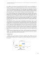
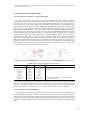
To grasp a user’s entrance or exit into a zone and count the number of people present, the suggested
system adopts PIR sensors. PIR sensors recognize the infrared light from human bodies and
movements in a zone to grasp a user’s presence. These PIR sensors, however, may not recognize any
presence if the user is located at a blinded area in the zone or the movement is too insignificant to be
sensed. Multiple sensors may be necessary depending on the size of the zone, and the number of users
in presence may not be recognized. Hence, the system suggested in this study uses the two PIR sensors
with an ID each at the entrance to count the number of users in the zone and check their entrance or
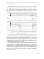
exit as in Figure 5(b). The system recognizes a user by means of the first PIR sensor in the order of IDs
saved in the PIR sensor, and then the entrance is recognized when the second PIR sensor recognizes
the user. Likewise, when the second PIR sensor recognizes movement and the user’s movement is
sensed by the first PIR sensor, an exit is recognized. The system’s PIR sensor transforms the infrared
light in the 95°×90° range into a voltage for sensing as shown in Figure 5(a). However, when the two
PIR sensors installed in the entrance of the zone maintain an existing wide angle as in Figure 5(a), it
frequently occurs that at the intersection of the two sensors, exit is mistakenly recognized right after
one’s entrance. The system, therefore, changed the sensing angle of the PIR sensors to a narrow angle
as in Figure 5(b) to correctly recognize entrance and exit.
Figure 5. Changes in the Sensing Angle of the PIR Sensors to Recognize One’s Presence Correctly
Packet
Table 2. Receiving packet information of PIR sensor
Length
No
Description
Header
10 bytes
Sensor Type
Serial ID
Node ID
Count
Battery
Sensor Data
Footer
2 bytes
6 bytes
2 bytes
2 bytes
2 bytes
6 bytes
3 bytes
0 / 1 / 2 / 3-4
5-6 / 7 / 8 /9
10-11
12-17
18-19
20-21
22-23
24-25 / 26-29
30-31 / 32
STX(0x7E) / Receiving(0x45) / 0x00 / Dest
Src / Length / Group ID / Type
0x0065
Sensing(Off : 0x0000, On : 0x0001) / Dummy
CRC / ETX(0x7E)
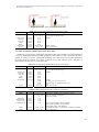
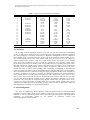
The packet of each PIR sensor transmitted to the gateway is 33 bytes in total as shown in Table 2.
Presence is sensed based on the received values of numbers 24 to 25. If more than one user enters the
same zone, the signals of entrance are delivered from the PIR sensors twice, and then the system
increases the number of recognized users at every signal reception and saves it in the database.
3.2.2. Receiving User-recognition Data
The suggested system adopts an ultrasonic sensor to recognize users. The sensor is installed at the
top of the entrance as in Figure 6, and the result is delivered except on the area covering the ground up
to the upper end of the user’s height. Table 3 shows the data packet structure of the ultrasonic sensor in
a table. The key information is received from packets 24 and 25 of the sensor data, and the received
values are compared with those in the user-recognition table stored in the database to recognize certain
users.
1236