1
Part No. EP59-10864
Iss. B
Non-contact Tonometer
Service Instructions
!
ALWAYS READ THE INSTRUCTIONS
Keeler Limited, Clewer Hill Road, Windsor, Berks, United Kingdom. SL4 4AA.Tel No. +44 (0) 1 753 857177
Fax No. +44 (0) 1 753 830247
CONTENTS
1.
Service Equipment Checklist and Technical Data
...1
2.
Pulsair Spare parts list
3.
Software installation guide
4.
Hardware set-up guide (Electronic unit)
5.
Dis-assembly and Re-assembly of the Pulsair2000/3000
8
6.
Dis-assembly and Re-assembly of the PulsairEasyEye
9
7.
Calibration andVerification Software Procedure
..10-22
8.
Cleaning of the Optics
..23
9.
Replacing the Air Filter
2
..3-5
.
.6-7
. ...24
10. Replacing the Umbilical Cord Assembly Pulsair2000/3000...25-26
11. Replacing the Umbilical Cord Assembly PulsairEasyEye
..27-28
CONTENTS
12. Replacing the Mainframe and pcb Assemblies
.29
13. Replacing the Pump and Pump Assembly Pulsair2000/3000..30
14. Replacing the Pump and Pump Assembly PulsairEasyEye
15. Set-up of Mainframe Mirror Assembly
.
16. Upgrade Power Supply pcb Pulsair2000
17. General Troubleshooting
.31
.. 32
..33
.
.34-38
18. Software Troubleshooting
....39-44
19. Replacement of Case Halves Pulsair2000/3000
...45-46
20. Replacement of Case Halves PulsairEasyEye
21. Replacement of thermal printer PulsairEasyEye
.
.47-48
..49
1. SERVICE EQUIPMENT CHECKLIST AND TECHNICAL DATA
1.
2401-P-5100
TUBE & CONNECTOR ASSEMBLY
2.
2401-P-5119
RS232 COMMUNICATION CABLE
3.
2401-P-5127
PC SERIAL PORT CABLE ASSEMBLY
4.
2401-P-6736
CALIBRATION ELECTRONIC UNIT
5.
2401-P-6787
CALIBRATION JIG Pulsair 2000/3000
6
2401-P-6005
CALIBRATION JIG
7.
EP79-09146
14/15mm SPANNER
8.
EP79-09154
DAQ CABLE ASSEMBLY
9.
EP79-09162
DAQ CARD 1200
10.
EP59-10901
25 WAY DONGLE
11.
EP84-01130
12.
RP18-00094
LOCTITE 601 ADHESIVE
13.
RP18-00318
BOSTIC CLEAR ADHESIVE
Pulsair (EasyEye)
SOFTWARE INSTALLATION DISC V2.7
CALIBRATION OF TEST JIG
This calibration function can only be carried out at KEELER LTD
The test unit must be returned to Keeler for recalibration periodically {once a year} as per the
due date on the back of electronic unit.
The items to be returned are as follows
1.
2.
3.
4.
CALIBRATION ELECTRONIC UNIT AND CABLE ASSEMBLES
TRANSDUCER ASSEMBLY
CALIBRATION JIG & DUMMY EYE
DAQ CABLE ASSEMBLY AND CARD 1200
PLEASE RETURN TO
KEELER LIMITED
CLEWER HILL ROAD WINDSOR
BERKSHIRE SL4 4AA
ATTN DAVE GRAHAM
PAGE 1
2.
Pulsair Spare parts list
Parts common to all models
2401-P-6744
EP39-05869
EP39-06896
EP39-05500
2110-P-7018
PP02-82056
EP79-40899
RP18-00094
EP39-04639
AIR FILTER ASSEMBLY
PUMP ADAPTOR
BSP\NPT ADAPTOR
BULB CONTACT
WIPES (PACK OF 24)
PTFE TAPE
CABLE-TIE
LOCTITE 601 RETAINER
NEEDLE VALUE
Pulsair model 2000 only
2401-P-6664
2401-P-6955
1024-P-5062
EP18-00203
EP18-00211
2401-P-6437
EP79-03334
EP79-05161
UMBILICAL CORD ASSEMBLY (2000)
P.C.B (2000)
BULB (2000)
CASE LEFT (2000)
CASE RIGHT (2000)
MAINFRAME ASSEMBLY
SPIRAL PIN
M3 INSERT
Pulsair model 3000 only
2401-P-6963
2401-P-6998
1024-P-5118
EP19-01848
EP19-01856
2401-P-6437
EP79-03334
EP79-05161
UMBILICAL CORD ASSEMBLY (3000)
P.C.B (3000)
BULB (3000)
CASE LEFT (3000)
CASE RIGHT (3000)
MAINFRAME ASSEMBLY
SPIRAL PIN
M3 INSERT
Pulsair model EasyEye only
2414-P-5002
2414-P-6002
EP29-50860
EP39-50643
EP39-50651
EP09-00501
EP09-00528
1024-P-5118
EP39-50387
UMBILICAL CORD ASSEMBLY (EasyEye
MAINFRAME ASSEMBLY
P.C.B (EasyEye)
DISPLAY P.C.B
SWITCH P.C.B
CASE RIGHT (EasyEye)
CASE LEFT (EasyEye)
BULB
SCREW PLUG
PAGE 2
PAGE 2
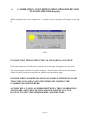
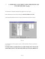
3. SOFTWARE INSTALLATION FOR PULSAIR CALIBRATION
ITEMS REQUIRED
1. NATIONAL INSTRUMENTS PCMCIA ANALOGUE TO DIGITAL CONVERTER
2. NATIONAL INSTRUMENTS SOFTWARE DISC (6.1V)
3. PULSAIR CALIBRATION SOFTWARE DISC (2.7.0V)
LOADING PROCEDURE
It is IMPORTANT that the National Instruments Software for the A.D.C is installed first to
minimise possible problems with the PCM CIA card
1. Place the NATIONAL INSTRUMENTS CD ROM DISC into CD-ROM drive bay.
2. DOUBLE CLICK My Computer on your Desktop.
3. DOUBLE CLICK the CD ROM icon /Drive Letter in My Computer.
4. DOUBLE CLICK onto the set-up icon.
5. Follow the on screen instructions. DOUBLE CLICK onto the install NI-DAQ option
FOR Windows 95 ONLY select the language setting (this should be highlighted in blue).
DOUBLE CLICK ok. Click next at each screen instruction until the install screen
appears, then click ok.
6.
When ok box has been clicked, the computer will automatically re-start.
7. After the computer has restarted, close the computer down completely and then switch
off.
8. Connect the ribbon cable EP79-09154 to the ADC PCMCIA card carefully.
9. Place the national instruments PCMCIA DAQ-1200 card carefully into the PCMCIA slot
in the computer, ensuring that the card is in the correct position.(as the instruction written
on top of the DAQ 1200 card) insert card
10. Turn the computer back on.
11. Windows 95/98 will automatically detect the new ADC card and install the appropriate
software for it.
12. CLICK ON TO START in main menu, then PROGRAMS and then select NATIONAL
INSTRUMENTS DAQ MENU. Run the NI-DAQ Configuration Utility programme
from the National Instruments DAQ program group, accept new device in socket 1or 2.
Page 3
3. SOFTWARE INSTALLATION FOR PULSAIR CALIBRATION
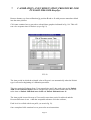
13. Single click Configure, which will find the ADC PCMCIA card. Follow the configuration
wizard. DO NOT change the AI Polarity/Range or Mode Settings to there default
settings. Change the AO Polarity to UNIPOLAR. Leave Accessory setting at none and
OPC to disabled, click ok to continue.
14. Then click X on the top right hand corner of the window for exit from configuration
utility. Click save if requested.
15. Remove NI-DAQ CD disc from CD bay
16. Place CD-ROM DISC for Pulsair Calibration (EP84-01130) into CD-ROM drive bay.
17. Double Click My Computer on main desktop.
18. Double Click CD-ROM icon.(CAL SW-V2-7) or (KEELER)
19. Double Click Calibration Software V2.7.0 folder(Calibration S)
20. Double Click SET-UP. Follow all on screen instructions.
21. Allow Windows to install the calibration software. Click OK to Tonometer set up, and
then click the install icon to install software. When completed click OK. Exit all open
files by clicking on the X in the right hand corner
DONGLE SECURITY DEVICE SOFTWARE INSTALLATION
INSTRUCTIONS
1. Double Click My Computer on main desktop
2. Double Click CD-ROM icon.(CAL SW-V2-7) or (KEELER)
3. Select and Double Click Hasp Command line Installer Latest version 120599 v3.83
4. Double Click Install Dongle
5. When Aladdin device Driver Installation Utility for Win32 screen instruction appears
Single Click OK
6. Exit all open files by clicking on the X in the right hand corner.
Page 4
3. SOFTWARE INSTALLATION FOR PULSAIR CALIBRATION
SHORT CUT INSTRUCTIONS
1. To obtain a Short Cut to the Calibration Software, first right click the mouse when in the
main desktop.
2. Select new then Select short cut (single click)
3. At command line Select browse (single click). At browse, select folder programme files
(double click).
4. At Programme files, select Tonometer, then (double click).
5. At tonometer, select eye symbol with Tonometer, then (double click).
6. At create shortcut, the command line will read C:\ Programme Files.
\Tonometer\Tonometer. exe select next then (single click).
7. When select a name for shortcut appears, it will read Tonometer. Single click Finish.
8. A short cut symbol of an eye will now appear. When you double click the eye symbol it
will take you into main Pulsair calibration software.
Page 5
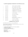
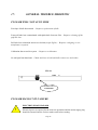
4.
CALIBRATION JIG ELECTRONIC UNIT
Take cable assembly 2401-P-5127 (PC SERIAL) and connect into fifteen way A.D.C female
socket on the front of calibration electronic unit (as per fig 1)
Take the other end of cable assembly and connect into the nine way male socket on the back of
laptop computer.
Plug transducer assembly into nine way female socket on the front of calibration unit, which is
engraved Pressure Transducer (as per fig 1)
Connect RS232 communication cable (2401-P-5127) into nine way male socket on front of
calibration unit, which is engraved Tonometer (as per fig 1)
Take the other end of the cable and connect into the back of the Pulsair tonometer mother unit.
FIG 1
Page 6
4.
CALIBRATION JIG ELECTRONIC UNIT
The last cable assembly to be connected is the national instruments ADC ribbon cable (EP7909154)
This is connected first to the multi way socket on the front of calibration unit engraved ADC
(as per fig 1).
Ensuring that the arrow on blue multi way ADC sockets aligns with the arrow on multi way, plug
on ribbon cable.
!!
NOTE! WHEN CONNECTING DAQCARD INTO THE LAPTOP
COMPUTER ENSURE LAPTOP IS SWITCHED OFF, AS THIS MAY
CAUSE DAMAGE TO THE DAQCARD DEVICE
Once connected, lock into position with locking clips. The smaller end is connected to the
DAQCard-1200 (EP79-09162) aligning first the white dots together as plug is pushed into
socket of DAQCARD.
Plug blue air tube assembly (2401-P-5100) into the front of the electronic unit marked AIR
INPUT
Connect dongle software security device to back of laptop computer. Locate into printer port
LP1.
!
NOTE! IF THE DONGLE IS NOT CONNECTED THE SOFTWARE WILL
NOT BE ACCESSIBLE
Page 7
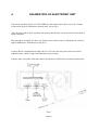
5. DIS-ASSEMBLY AND RE-ASSEMBLE OF PULSAIR
PULSAIR 2000/3000
1. Remove the four M4 screws and shakeproof washers holding the base moulding to the
Pulsair mother unit (as per fig 2)
FIG 2
2. While in same position remove the two M4 transit screws and shakeproof washers
holding the pump assembly in position at location B (as per fig 3)
FIG 3
3. Remove the four M5 screws and shakeproof washers holding the top moulding to the
mother unit as seen in fig 3 position A
Ensure when removing top moulding that the white microswitch plunger is not mislaid
4. Re-assemble in reverse order fitting white plunger first
PAGE 8
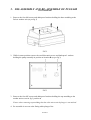
6. DIS-ASSEMBLY AND RE-ASSEMBLE OF PULSAIR
EasyEye
1. Remove the six M4 screws and shakeproof washers holding the base moulding to the
Pulsair top unit removing the wall/desk support A first to reveal the two hidden screws
under the support (as per fig 2A)
A
B
FIG 2A
2. While in same position remove the pump transit screw holding the pump assembly in position
at location B (as per fig 2A)
Ensure when removing top moulding that the white microswitch plunger is not mislaid
3. Re-assemble in reverse order fitting white plunger first
PAGE 9
7.
CALIBRATION AND VERIFICATION PROCEDURE FOR
PULSAIR 2000-3000- EasyEye
1. Remove the 8 screws holding the top and bottom mouldings from the Pulsair 2000/3000
mother unit (as in fig 2).Remove the 6 screws for the Pulsair EasyEye refer to fig 2A
2. Remove the 2 transit screws if fitted from the pump assembly (as in fig 3) or fig 2A for
Pulsair EasyEye
3. Disconnect the blue pipe from the umbilical cord assembly, which is connected to the
filter, which is located in the inner part of the Pulsair mother unit.
4. Connect the blue pipe from umbilical cord assembly and the connector assembly (2401-P5100) from the calibration pressure gauge together and then into filter.
5. Place the Pulsair mother unit back into bottom moulding (do not replace the screws at
this stage) as this is only a method of holding the Pulsair while calibration and repair
work is taking place.
6. Place the hand unit assembly onto the calibration jig, first removing puff tube shroud and
trim ring from front of the hand unit assembly. Procedure 19 and 20 (fig 34 and 34A).
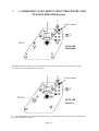
7. Locate the hand unit assembly from the Pulsair 2000/3000 onto the 3 pillars A - B and C
and slide into the central locking device D (as per fig 4) LOCK INTO POSITION
WITH LOCKING KNOB. When calibrating Pulsair Easyeye use the jig shown in fig 4a
8. Connect RS232 communication cable (2401-P-5119) from calibration electronic unit to
the back of Pulsair mother unit.
!
ELECTRIC SHOCK HAZARD
Electrical power is required for the next operations
9. Fit the mains lead to underside of the Pulsair 2000/3000 mother unit (DO NOT
SWITCH ON). Fit the lead from the power supply for the Pulsair EasyEye to the front or
back of the mother unit
IF MAINFRAME ASSEMBLY OR MAIN P.C.B ASSEMBLY HAS BEEN
REPLACED REFER TO MAINFRAME MIRROR SETTING PROCEDURE
(SECTION 15)
Page 10
7.
CALIBRATION AND VERIFICATION PROCEDURE FOR
PULSAIR 2000-3000-EasyEye
X
LOCKING SCREWS
4
Y
Z
E
4
FIG 4
D
PULSAIR
2000/3000
C
A
B
The X Y Z indecking head is now interchangeable between the two calibration jigs undo the two locking
screws and remove the head from the two dowels.
X
LOCKING SCREWS
4
Z
Y
E
4
FIG 4A
D
PULSAIR
EasyEye
1
2
3
10. Once the Pulsair is in position on calibration jig you must then follow the on screen instructions
from the calibration software.
Page 11
6.
CALIBRATION AND VERIFICATION PROCEDURE FOR
PULSAIR 2000-3000-EasyEye
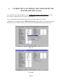
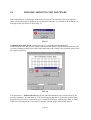
Select the software icon, which is identified by an eye symbol on main screen menu. Double
click and this will take you into the main Pulsair menu (as per fig 5)
FIG 5
You are required to select a Pulsair instrument type; to achieve this you must first click on
select instrument type box. A tonometer menu will appear (as per fig 6)
FIG 6
You must now select a Pulsair type to be calibrated by clicking onto appropriate Pulsair
instrument type. This is verified by a black dot in the circular window
Page 12
6.
CALIBRATION AND VERIFICATION PROCEDURE FOR
PULSAIR 2000-3000-EasyEye
WARNING IF INCORRECT PULSAIR TYPE IS SELECTED THE WRONG
CALIBRATION DETAILS WILL BE INSTALLED INTO THE PULSAIR
EPROM AFTER CALIBRATION
Once selected press continue box to continue, this will take you back to main Pulsair menu
(as per fig 5)
You then have a choice of six instruction boxes. If calibration is required, select Calibrate
Tonometer and follow on screen instructions.
When screen instruction has been carried out, press continue to proceed to the next screen
menu. This is for setting of pump pressure follow on screen instructions (as per fig 7)
!
THE PULSAIR TYPE IS DISPLAYED AT THE TOP OF ALL DATA AND
INFORMATION MENUS ENSURE CORRECT TYPE HAS BEEN
SELECTED
FIG 7
Press continue box and this will take you to DATA ENTRY. This information data is required
for KEELER records. Fill in data were required (as per fig 8)
FIG 8
Page 13
6.
CALIBRATION AND VERIFICATION PROCEDURE FOR
PULSAIR 2000-3000-EasyEye
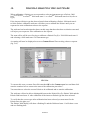
When completed press the continue box. A switch on screen message will appear (as per fig
9)
FIG 9
ENSURE THAT THIS INSTRUCTION IS FOLLOWED AS STATED.
If the instructions are not followed as stated an error message will appear (as per fig 10)
The error message will take 16 seconds to appear. You must then click on the OK button,
which will take you back to main Pulsair menu to start procedure again.
ENSURE WHEN COMMUNICATION IS MADE WITH THE PULSAIR
THAT THE PULSAIR IS NOT SWITCHED OFF DURING THE
CALIBRATION PROCEDURE.
AS THIS WILL CAUSE AN ERROR BETWEEN THE CALIBRATION
SOFTWARE AND THE PULSAIR AND WILL RESULT IN YOU
HAVING TO EXIT THE PROGRAMME AND RESTART.
Page 14
7.
CALIBRATION AND VERIFICATION PROCEDURE FOR
PULSAIR 2000-3000-EasyEye
FIG 10
Fit dummy eye block to calibration jig in position E (as per fig 4 and 4A)
Follow on screen instructions for setting of K FACTOR VALUE (as per fig 11) the position
is achieved by using the X Y Z adjusters on the calibration jig (as per fig 4 and 4A)
REFER TO SETTING OF MAINFRAME MIRROR ASSEMBLY PROCEDURE TO
ENSURE
CORRECT METHOD FOR SETTING IS OBTAINED (SECTION 15)
FIG 11
Once correct K VALUE has been obtained the K VALUE box will change from red to green
to indicate that setting is correct.
Click onto continue box to proceed to next on screen instruction as seen in fig11A
FIG 11A
Page 15
7.
CALIBRATION AND VERIFICATION PROCEDURE FOR
PULSAIR 2000-3000-EasyEye
Remove dummy eye from calibration jig position E and re-fit with pressure transducer block
into the same position
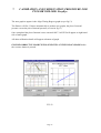
Click onto continue box to proceed to solenoid time graph as indicated in fig 11A. This will
test valve response time for Pulsair (as per fig 12)
FIG 12
The time period in which the solenoid value will open is set automatically when the Pulsair
type is selected at beginning of calibration procedure.
This time period will change from 3.1ms normal time and 3.4ms turbo time on the Pulsair
3000 and the Pulsair EasyEye then to a higher time period of 4ms normal time and 4.3ms
turbo time on Pulsair 2000 mod state 1to10 and Pulsair 2000 mod state 11.
The time period is tested in steps of .3ms until correct time period is achieved and the
Pressure difference is not > than the acceptable tolerance set in the software,
Each level is verified with 8 test puffs, (as seen in fig 12).
Once completed click continue box to proceed to next instructions.
Page 16
6.
CALIBRATION AND VERIFICATION PROCEDURE FOR
PULSAIR 2000-3000- EasyEye
You must now click onto the OK box below Calibration eeprom Values Written this will
now transfer calibration data into eeprom (as per fig 15).
Once completed the main data information box will appear again (as per fig14)
A tick will now be displayed in the EEPROM Status box. This will now verify that the eeprom
data has been succesfully transferred as seen next to the EEPROM Data Written statement
FIG 15
FIG 15A
Page 16
7.
CALIBRATION AND VERIFICATION PROCEDURE FOR
PULSAIR 2000-3000- EasyEye
The next graph to appear is the Align Timing Regress graph (as per fig 13)
The Pulsair will fire 32 times automatically to produce two graphs, the plot of external
pressure versus the plot of internal pressure (as seen in fig 13)
Once completed the plot of internal versus external ADC VALUES will appear on right hand
side of main graph.
All other calibration details will appear at bottom of graph.
ENSURE CORRECT PULSAIR TYPE IS SELECTED AT THE TOP OF GRAPH before
the continue button is pressed
FIG 13
Page 17
7.
CALIBRATION AND VERIFICATION PROCEDURE FOR
PULSAIR 2000-3000- EasyEye
The tonometer s Calibration data details will appear next (as per fig 14)
Ensure all details are correct before clicking onto WRITE EEPROM VALUES,
At this stage all calibration details are ready to be transferred to the Pulsair eeprom,
FIG 14
A verification box will now appear to ensure you that the details will now be transferred
(as per fig 15)
ENSURE WHEN CALIBRATION IS COMPLETED THAT THE PUMP
ADAPTOR LOCK NUT IS SEALED WITH LOCTITE 601 ADHESIVE
Page 18
Page 19
6.
CALIBRATION AND VERIFICATION PROCEDURE FOR
PULSAIR 2000-3000- EasyEye
You must now click onto the OK box below Calibration eeprom Values Written this will
now transfer calibration data into eeprom (as per fig 15).
Once completed the main data information box will appear again (as per fig14)
A tick will now be displayed in the EEPROM Status box. This will now verify that the eeprom
data has been succesfully transferred as seen next to the EEPROM Data Written statement
FIG 15
FIG 15A
Page 19
7.
CALIBRATION AND VERIFICATION PROCEDURE FOR
PULSAIR 2000-3000- EasyEye
At this stage if the calibration data has not been transferred, the continue button will not be highlighted
and will not allow you to proceed,
If you were to click onto Print tables or Save tables, a warning message will appear (as per fig 16) as a
reminder that you must write to the eeprom before the completion of the calibration.
When calibration is completed, click continue box to return to main menu.
FIG16
PAGE 20
7.
CALIBRATION AND VERIFICATION PROCEDURE FOR
PULSAIR 2000-3000- EasyEye
To verify calibration you must start at main Pulsair menu as before
Then Select Instrument Type where you must then select correct Pulsair to be checked i.e.
Pulsair 2000 mode state 0-10 Pulsair 2000 mode state 11 Pulsair 3000 Pulsair EasyEye
Then select CHECK CALIBRATION by clicking onto the highlighted Check Calibration box.
All on screen instructions except for the setting of pump pressure (see note) are the same as
the previous calibration instructions, but will change after the Align Timing Regress graph as
(per fig 13).
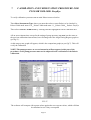
At this stage a new graph will appear, which is the comparison graph (as per fig17). This will
verify the calibration
NOTE! The pump pressure on screen instruction will not appear in this part of the
procedure, as the pump pressure must not be adjusted in the verification of the Pulsair
calibration.
FIG 17
The software will compare old eeprom values against the new eeprom values, which will then
be calculated to see if they correspond
Page 21
7.
CALIBRATION AND VERIFICATION PROCEDURE FOR
PULSAIR 2000-3000-EasyEye
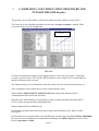
The pressure errors of the Pulsair will now be displayed on the graph (as seen in fig17)
The errors at 10 and 20mmHg should not exceed more than plus or minus 1 mmHg. If this
occurs the Pulsair must be recalibrated.
Plot of Old minus New
Pressure
FIG 17A
If when checking the old eeprom values against the new values (as seen in fig 17A) the Best
Contrast is set at a value of 255 and the KIEE normal is set at a value of 255 it would indicate
that the calibration data is corrupt.
The Pulsair must now be recalibrated, as the unit will not auto fire when focussed on the eye.
Once completed, click continue box to return to main Pulsair menu
When finished, DISCONNECT MAINS LEAD from mother unit. Remove RS232
communication cable from back of Pulsair.
Refit blue pipe from umbilical cord assembly to filter assembly and add tested label (EP3905372) to top of pump assembly diaphragm block
Remove hand unit from calibration jig
Re-assemble puff tube shroud and trim ring to hand unit and locking screw. Refer to fig34
and fig34A
Re-fit transit screws to pump and 8 screws holding the top and bottom moulding (Pulsair 2000/3000)
Re-fit the 6 screws holding the top and bottom moulding to the Pulsair Easyeye in reverse order.
Refer to procedure 5 and 6.
Page 22
8.
CLEANING OF THE PULSAIR OPTICS
1. First remove puff tube shroud and eyepiece shrouds before cleaning procedure can
take place.
!
Ensure when cleaning the lenses that they are not touched with the
fingers as these are coated lenses and will easily smear
2. Using the cleaning wipes (2110-P-7018) in a circular motion remove any dirt deposits
from front of puff Tube assembly and viewing lens assembly (as per fig18)
CLEAN
THIS FACE
Pulsair 2000/3000
PULSAIR EasyEYE
FIG 18
CLEAN
THIS FACE
CLEAN
THIS FACE
Page 23
9.
REPLACEMENT OF AIR FILTER
ELECTRIC SHOCK HAZARD
!
Electrical power is not required for this operation and the mains supply plug
Should be removed before starting next operation.
1. Remove top and bottom mouldings as described in procedure 5 and 6
2. Disconnect blue tube from both sides of filter assembly (as in fig 19)
3. Remove filter from bracket and replace with new filter assembly (2401-P-6744)
Reconnect blue tubes
4. Refer to calibration procedure 7 for recalibration instructions.
5. Refer to re-assemble of Pulsair procedure 5 and 6
FIG 19
Page 24
Page 24
10.
UMBILICAL CORD ASSEMBLY REPLACEMENT
PULSAIR 2000/3000
!
ELECTRIC SHOCK HAZARD
Electrical power is not required for this operation and the mains supply plug
Should be removed before starting next operation.
1. Remove the Pulsair top and bottom mouldings as described in procedure 5 and 6
2. Disconnect blue tube from filter in mother unit.
3. Remove either M4 nut from earth stud on microswitch bracket or M4 screw from side of
transformer
4. Remove cable ties holding earth wiring to wire loom, unplug 8 way Molex connector
from power supply P.C.B.
5. Remove M3 screw holding P clip and blue pipe from power supply P.C.B
6. Remove umbilical cord assy from mother unit.
7. At hand unit end, remove puff tube shroud, trim ring, eyepiece shroud and M3 locking
screw at bottom of hand moulding (as per fig 34).
8. Remove top hand unit moulding
9. Disconnect Molex connector containing 8 wires from P.C.B.(as per fig 20)
10. Remove the M3 screw from centre of mainframe holding earth wires (as per fig 20).
11. Remove the screw holding yellow wire and bulb contact to top of mainframe. Cut the blue
tube from hand unit value to mainframe and then remove the umbilical cord assembly.
NOTE! The blue tube removed from hand unit value must be replaced before reassemble
can take place.
12. Re-assemble new umbilical cord assy in reverse order. Refer to calibration procedure 7.
For re-calibration.
Page 25
10.
UMBILICAL CORD ASSEMBLY REPLACEMENT
PULSAIR 2000/3000
BULB CONTACT
SCREW
MOLEX
CONNECTOR
M3 CENTRE
SCREW
AND
EARTH WIRES
BLUE TUBE
FROM VALVE
FIG 20
Page 26
11.
UMBILICAL CORD ASSEMBLY REPLACEMENT
EasyEye
!
ELECTRIC SHOCK HAZARD
Electrical power is not required for this operation and the mains supply plug
Should be removed before starting next operation.
1. Remove the Pulsair top and bottom mouldings as described in procedure 5 and 6
2. Disconnect blue tube from filter in the mother unit.
3. Unplug the 8 way Molex connector from power supply P.C.B.
4. Remove the umbilical and cable gland assemble from the mother unit.
5. At the hand unit end, unscrew the puff tube shroud and the end cap from the hand unit
mouldings refer to Fig 34A, remove the four locking screws holding the top hand unit
moulding to the bottom moulding.
6. Remove the top hand unit moulding and the front panel assembly
7. Unplug the 8-way molex connector from the P.C.B and remove the clip from the coil on
the handunit value (as per fig 20A).
8. Remove the M3 screw from centre of mainframe holding it to the bottom hand unit
moulding (as per fig 20A).
9. Cut the blue tube from hand unit value to the mainframe, disconnect the blue tube from
the reservoir you now remove the umbilical cord assembly.
NOTE! The blue tube removed from hand unit value must be replaced before reassemble
can take place.
12. Re-assemble new umbilical cord assy in reverse order. Refer to calibration procedure 7.
For re-calibration.
Page 27
11.
UMBILICAL CORD ASSEMBLY REPLACEMENT
EasyEye
BULB CONTACT
SCREW
MOLEX
CONNECTORS
M3 CENTRE
SCREW
CLIP (COIL)
BLUE TUBE
FROM VALUE
FIG 20A
Page 28
12. REPLACEMENT OF MAINFRAME & P.C.B. ASSEMBLIES
ELECTRIC SHOCK HAZARD
!
Electrical power is not required for this operation and the mains supply plug
Should be removed before starting next operation.
1. Disconnect the umbilical cord assembly from hand unit as described in the previous
procedure 10 and 11. (from operation 7 onwards is required)
2. Remove the four screws holding P.C.B. to mainframe and earth wire; disconnect blue tube
to transducer. Replace defective part (mainframe assembly or main hand unit P.C.B)
3. Ensure when re-assembling that the serial number label is removed from the P.C.B and re
attached to the top of the mainframe. The insulation tape must be fitted to the P.C.B with
7mm cut out to clear solder earth pad (as per fig 21) and blue tube to transducer is
reconnected from mainframe assembly with brass restrictior.
4. Fit M2 washer between bulb contact and P.C.B prior to the fitting of the mainframe;
ensure the second bulb contact is fitted to the mainframe and the earth lead is attached.
5. Re-assemble umbilical cord assembly to bottom hand unit moulding.
6. Fit the dummy handunit case (EP29-04207) Pulsair 2000/3000(EP39-50272) Pulsair
EasyEye prior to calibration so setting of mainframe mirror assembly can be carried out.
(See fig 24 procedure 15.) and fig 24A for Pulsair Easy Eye ensure the calibration ring is
attached
7. Refer to calibration procedure 7 for recalibration instructions.
(CUT OUT 7MM SQUARE IN RP99-99325 TAPE
TO CLEAR SOLDER EARTH PAD)
ATTENTION
Observe precautions
For handling
Electrostatic
Devices
FIG 21
Page 29
RP 99-99325
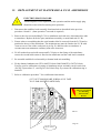
13.
REPLACEMENT OF PUMP PARTS
PULSAIR 2000/3000
ELECTRIC SHOCK HAZARD
!!
Electrical power is not required for this operation and the mains supply plug
should be removed before starting next operation.
1. Disconnect blue tube fitting from elbow connection on side of pump adaptor as in
(fig22A)
2. Remove the three mains wires connected to the coil and valve assembly (BLACK,
WHITE, GREEN/YELLOW) as in (fig 22B).
3. Remove coil and valve assembly from side of pump adaptor as in (fig 22C), using 14 and
15mm spanners.
4. Remove filter silencer from underside of pump adaptor fitted to pump block (as per fig
22D).
5. Remove pump adaptor (EP39-05869) and BSP/NPT adaptors (EP39-06896) from pump
(as per fig 22E) using 14mm spanners
ENSURE WHEN REFITTING BSP/NPT adaptors a small amount of PTFE tape (PP0282056) is secured around threads
6. Replace faulty components and re-assemble in reverse order.
7. Refer to calibration procedure 7 for re-calibration instructions.
L1 N
D
B
E
A
C
FIG 22
Page 30
14.
REPLACEMENT OF PUMP PARTS
PULSAIR EasyEye
ELECTRIC SHOCK HAZARD
!!
Electrical power is not required for this operation and the mains supply plug
should be removed before starting next operation.
1. Disconnect blue tube fitting from elbow connection on side of pump adaptor as in
(fig22A/A)
2.
Remove the two wires connected to the coil and valve assembly (BLACK, WHITE ) as
in (fig 22A/B)
3. Remove coil and valve assembly from side of pump adaptor as in (fig 22A/C ) using a 14
and 15mm spanners.
4. Remove filter silencer from underside of pump adaptor fitted to pump block (as per fig ).
5. Remove pump adaptor (EP39-05869) and BSP/NPT adaptors (EP39-06896) from pump
(fig 22A/D) using 14mm spanners
6. ENSURE WHEN REFITTING BSP/NPT adaptors a small amount of PTFE tape (PP0282056) is secured around threads
7. Replace faulty components and re-assemble in reverse order.
8. Refer to calibration procedure 7 for re-calibration instructions.
D
B
C
A
FIG 22A
Page 31
15.
SETTING OF MAINFRAME MIRROR ASSEMBLY
AND TARGET FOR PULSAIR EasyEye
1. Place the hand unit assembly onto calibration jig as shown in (FIG 4 or 4a). NOTE! At
this stage ensure that the dummy hand unit case is fitted.
2. Refer to calibration procedure 7 and follow on screen instructions for calibration until the
setting of K value is required (as per fig 23)
3. Loosen the two screws holding the mirror assembly in position on mainframe (as per fig
24) and adjust until the best reading is obtained on K value. Refer to example shown
below.
FIG 23
.
4.
A and C photodiode value should be set equally first before obtaining the best K value.
Once achieved, lock mirror assembly into position as per fig 24.
5. Only on the Pulsair EasyEye will you see the bow tie target when you view through the
Eye lens, the target must be adjusted to the central position as shown in fig 24A.
Pulsair EasyEye
Adjust target
screws
Adjust mirror
screws
BOW TIE
TARGET
FIG 24
FIG 24A
PAGE 32
Eye lens
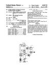
16.
UPGRADE OF POWER SUPPLY (P.C.B.)
THIS PROCEDURE APPLIES TO PULSAIR 2000 ONLY
1. Verify voltage at diode D6 (anode side of diode) and PL4/1 connectors on power supply
P.C.B. as per figure 25. If voltage is 17 volts, the power supply P.C.B. must be modified.
ELECTRIC SHOCK HAZARD
!!
Electrical power is not required for this operation and the mains supply plug
Should be removed before starting next operation.
2. First remove P.C.B. from the mother unit by disconnecting wire looms PL1-PL4 and PL3
From the P.C.B plug connections.
3. Remove the five-m3 screws holding the power supply P.C.B. in position.
4. The P.C.B. can now be removed.
5. The next part of this procedure should only be carried out on Pulsair 2000 as the Pulsair
3000 has a higher drive voltage of 23.8 volts on the solenoid value
6. REPLACE resistor R4 from 1k5 to 1k8 OHMS (on Pulsair 2000 only) this will increase
voltage at D6 from 17 volts to 19.95 volts which enables the solenoid value to be more
responsive.
7. Re-assemble power supply P.C.B. in reverse order.
8. Refer to calibration procedure 7. For re-calibration.
R4
ATTENTION
Observe precautions
For handling
Electrostatic
Devices
C12
Page 33
17.
GENERAL TROUBLE SHOOTING
PULSAIR WILL NOT AUTO FIRE
Envelope of bulb discoloured - Requires replacement of bulb
Front puff tube lens contaminated with splash back from tear film - Requires cleaning off the
puff tube lens
Puff tube lens orientation incorrect or broken (as per fig 26) - Requires realigning or new
mainframe is required
Calibration data erased in eeprom - Requires recalibration
No red light from hand unit - Check 6volt line to bulb and bulb contacts are not broken
FIG 26
NOTE! Correct
orientation
PULSAIR HAND UNIT FAILURE
ELECTRIC SHOCK HAZARD
!
Electrical power is required for the next test operations and the mains supply plug
should be inserted into the Pulsair mother-unit before starting.
Page 34
17.
GENERAL TROUBLE SHOOTING
Hand unit display will not function
Pulsair 2000/3000
Verify the T2amp fuse inside the Pulsair mother unit
If faulty remove and replace.
Verify crimps on fuse holder
If faulty remove crimps and solder wires to fuse holder.
Verify the 10volt AC supply from transformer to power supply. The red and orange wires are
required for this test (Edge connector PL1 pins 3&4)
If there is low or no voltage verified at this point, the transformer must be replaced.
Verify the 5volts DC supply from power supply P.C.B in mother unit, to hand unit. The black
and red wires are required for this test (PL4 edge connector on power supply PCB pins 1&4)
If there is low or no voltage verified at this point, the power supply P.C.B must be replaced
Verify the 5volts DC supply from power supply P.C.B to the inside of the hand unit main P.C.B.
The black and red wires are required for this test (Edge connector PL2 on main P.C.B 1&4)
If there is low or no voltage verified at this point, the umbilical cord assembly must be replaced
Hand unit will not puff on demo
Pulsair 2000/3000
Verify the 400ma fuse inside mother unit
If faulty remove and replace
Verify crimps on fuse holder
If faulty replace crimps and solder wires to fuse holder
Verify the 20volts AC supply from transformer to power supply P.C.B. The Grey and blue wires
are required for this test (Edge connector PL1 on power supply P.C.B pins 1&2)
If there is low or no voltage verified at this point, the transformer must be replaced
Page 35
17.
GENERAL TROUBLE SHOOTING
Verify the 19.9volts DC supply on the Pulsair 2000 and 23.8volts DC on the Pulsair 3000 from
the power supply P.C.B in the mother unit to the hand unit solenoid valve. The black and blue
wires are required for this test
(Edge connector PL4 on power supply PCB pins 1&2)
If there is low or no voltage verified at this point, the power supply P.C.B must be replaced
Verify the 19.9volts DC supply on the Pulsair 2000 and 23.8volts DC on the Pulsair 3000 in side
the hand unit on the main P.C.B. The black and blue wires are required for this test (Edge
connector PL2 on main P.C.B pins 1&3)
If there is low or no voltage verified at this point, the umbilical cord assembly must be replaced
Verify inside Pulsair mother unit the inline fuse to the pump (T250ma)
If faulty remove and replace
Verify airflow from pump.
If no airflow from the pump the pump must be replaced
PULSAIR MOTHER UNIT NO POWER
Pulsair 2000/3000
Verify fuses on under side of Pulsair mother unit
If faulty remove and replace
Verify mainswitch on side of Pulsair mother unit
If faulty remove and replace
Verify Pulsair mains power cord lead
If faulty replace
INCONSISTENT AIR FLOW
Check pump adaptor for air flow
If faulty replace
Check pump assembly for airflow
If faulty replace
Page 36
17.
GENERAL TROUBLE SHOOTING
BATTERY not charging Pulsair easyeye
Check 5amp fuse inside Pulsair
If faulty replace
PRINTER will not function Pulsair easyeye
Check paper is present inside printer
Check lid is shut
Check printer is switched on
If Printer is faulty refer to section 21
NO POWER Pulsair easyeye
Check voltage from wall mounted P.S.U
12volts should be present.
If faulty replace
NO POWER Pulsair easyeye MOTHER UNIT
Verify the voltages from the mother unit power supply P.C.B
Check the voltages at the molex connector SK1
SK1 pin8 (orange) = common
SK1 pin7 (blue) = 24volts
SK1 pin6 (yellow) = 6volts
SK1 pin5 (red)
= 5volts
SK1 pin4 (black) = common
SK1 pin3 (white) = -12volts
If faulty replace the P.S.U
Page 37
17.
GENERAL TROUBLE SHOOTING
NO POWER Pulsair easyeye HAND UNIT
Verify the voltages at the hand unit P.C.B
Check the voltages at the Molex connector SK2
SK2 pin8 (orange) = common
SK2 pin7 (yellow) = 6volts
SK2 pin6 (blue) = 24volts
SK2 pin5 (red) = 5volts
SK2 pin4 (black) = common
SK2 pin3 (white) = -12volts
If faulty replace the pulsair umbilical cord assembly (Procedure 11)
Page 38
18.
TROUBLE SHOOTING THE SOFTWARE
When calibrating or verifying the calibration of the Pulsair the software has been designed to
show warning messages or graphs to give a indication that there is a problem with the Pulsair at
this stage of the procedure (as seen in fig 27)
FIG 27
Communication Link Error (as shown in fig 27) is an indication that the RS232
communication cable has not been connected between the Pulsair and calibration electronic unit,
or when switching on the Pulsair after being instructed by the software, has not taken place in the
time period requested.
FIG 28
The graph above - Puff Pressure Error (fig 28) indicates that there is no pressure seen by the
pressure transducer on calibration jig. This would suggest that there is a pressure problem from
pump (no air pressure!) or that there may be a connection problem with air pipes from air filter!
If the correct pump pressure is not set to 21psi this warning graph will then also appear.
Page 39
18.
TROUBLE SHOOTING THE SOFTWARE
The graph below (Pressure versus Time) shows how the Pulsair calibration software has tried to
set a Pulsair 3000 valve time out setting to a time period of 3.1ms (as shown in fig 29) this has
not been achieved as illustrated.
Once this has occurred the software is designed to go back above the point of failure to try and
reset the time period by reducing the time period s adjustment in step of.06ms.
This has also failed (as seen in fig 29).
At this stage the umbilical cord assembly must now be replaced, as the valve is faulty.
Refer to procedure 9 and 9A for replacement of umbilical cord assembly.
FIG 29
The graph reference (fig 30) Puff PressureWarning is an indication that the pump pressure has
fallen out of the recommended calibration specification pressure setting of 21psi.
The reason for this could be as follows! Low output pressure from pump assembly, Pump adaptor
faulty or requires internal cleaning. Air filter blocked requires replacing.
Leak in main air system (mother unit or hand unit)!
Page 40
18.
TROUBLE SHOOTING THE SOFTWARE
When fault of pressure problem has been identified and then rectified the Pulsair must be
recalibrated.
FIG 30
The graph reference (fig31 and 31A) INTERNAL PUFF WARNING and Run time error 6
overflow indicates that there is no internal pressure profile or a low signal from the hand unit s
P.C.B pressure transducer (as seen in fig 31 and 31A).
Run time error 6 overflow will only appear on Pulsair mod state 0-10 units
A faulty internal transducer, the air pipe not connected to transducer, blockage in air pipe
restrictor could be the cause of this problem.
ELECTRIC SHOCK HAZARD
!!
Electrical power is not required for this operation and the mains supply plug
should be removed before starting next operation.
If found to be the transducer on the hand unit Printed circuit board, the printed circuit board must
be replaced
Reference procedure 12. Replacement of Mainframe and P.C.B assemblies.
After replacement the Pulsair must be recalibrated - refer to recalibration procedure 7.
Page 41
18.
TROUBLE SHOOTING THE SOFTWARE
FIG 31
FIG 31A
Page 42
18.
TROUBLE SHOOTING THE SOFTWARE
In reference to (fig 32) Alignment of K value there is no reading shown in the K value box, only
0.000 in red.
This is a warning that the bulb is not functioning correctly, which may be caused by a loose or
broken bulb contact, a blown bulb or a faulty bulb
Verify the voltage to bulb from power supply (check 6-volt power line),
Verify the main frame optical system; check fig 24 or 24a of procedure15. (Setting of
mainframe mirror assembly).
Ensure transducer has not been left on calibration jig when setting K value, this would give a
similar fault
FIG 32
If the dongle security device is not connected into the back of laptop computer which is located
into printer port LP1, a Error message will appear (as per fig 33)
Fig 33
Page 43
18.
TROUBLE SHOOTING THE SOFTWARE
When calibrating a Pulsair you are requested to select an instrument type a Pulsair 3000
Pulsair EasyEye or a Pulsair 2000 mod state 11 or a Pulsair 2000 mod state 0 to10 (refer to
fig 6).
If the incorrect Pulsair type has been selected when calibrating a Pulsair 2000 mod state 0
to10 the Pulsair calibration software will allow you to calibrate the Pulsair until you are
requested to write calibration values to the eeprom.
The software has been designed to detect at this stage that there has been a selection error and
will reject your request to write calibration to the eeprom.
The same effect will be seen if trying to calibrate a Pulsair EasyEye/ 3000/2000 mod state 11
and selecting a 2000 mod state 0-10 instrument type
A warning will now be displayed as seen as Comms Error! Error writing values to eeprom
(fig 33A)
FIG 33A
To correct this error you must first click onto the OK on the Comms error box and then click
onto the continue box to return to the start of the calibration procedure 7.
You must then re-select the correct Pulsair to be calibrated and re-start the calibration.
The software will not be able to distinguish between the Pulsair EasyEye Pulsair 3000 and the
Pulsair 2000 mod state 11 after calibration if the incorrect Pulsair type has been selected
To verify that the correct type after calibration has been selected you must auto fire the
Pulsair on to the glass eye.
The Pulsair 3000 display will show a flashing Er and the 2000 mod state 11 will show a zero
and two flashing dots.
PAGE 44
19.
REPLACEMENT OF CASE HALVES
PULSAIR 2000/3000
ELECTRIC SHOCK HAZARD
!
Electrical power is not required for this operation and the mains supply plug
Should be removed before starting next operation.
1. Unscrew puff tube shroud and remove (as per fig 34)
2. Remove trim ring by sliding over case halves
3. Unscrew eye piece shroud and remove
4. Remove M3 locking screw from bottom of top case half
5. Remove top case half
6. Unscrew M3 centre locking screw holding mainframe and remove.
7. Remove bottom case half.
8. Replace bottom case halves with new adding spirol pin( EP79-03334) and M3 insert
(EP79-01561) , add bostic clear adhesive to slot in case half to retain display p.c.b
9. Re-assemble in reverse order
PAGE 45
19.
REPLACEMENT OF CASE HALVES
PULSAIR 2000/3000
PUFF TUBE
SHROUND
EYE PIECE
SHROUND
TRIM
RING
FIG 34
M3 LOCKING
SCREW
PAGE 46
20.
REPLACEMENT OF CASE HALVES
PULSAIR EasyEye
ELECTRIC SHOCK HAZARD
!
Electrical power is not required for this operation and the mains supply plug
Should be removed before starting next operation.
1. Unscrew the puff tube shroud from the case halves and remove (as per fig 34A)
2. Unscrew end cap on unbilical cord assembly and remove from case halves
(As per fig 34A)
3. Push the Allen key supplied through the four screw plugs to access the cap headed screws
Unscrew the four screws holding the two cases halves together.
4. Remove the top case half
5. Remove the front panel assembly.
6. Unscrew the M3 centre locking screw holding the mainframe and P.C.B.
7. Remove the bottom case half
8. Replace top and bottom case half adding new spiral pin (EP79-03334) to top case half and
led covers (EP39-50387) if required
9. Re-assemble in reverse order.
PAGE 47
20.
REPLACEMENT OF CASE HALVES
PULSAIR EasyEye
4 LOCKING
SCREWS
AND PLUGS
PUFF
TUBE
END CAP
FIG 34A
FRONT
PANEL
M3 CENTRE
LOCKING
SCREW
BOTTOM
CASE
PAGE 48
PAGE 49
21. REPLACEMENT OF THERMAL PRINTER (PULSAIR EasyEye)
!
ELECTRIC SHOCK HAZARD
Electrical power is not required for this operation and the mains supply plug
Should be removed before starting next operation.
ATTENTION
Observe precautions
For handling
Electrostatic
Devices
1. Unscrew the top assembly from the base as described in section 6
2. Unplug the printer switch wiring loom from the powers supply P.C.B
3. Unplug the two ribbon cables from the lid which are connected to the power supply
P.C.B
4.
Remove the three screws from inside of the lid holding the printer in position
5. Remove the printer p.c.b located on the side of the top moulding.
6. Open the printers lid and then extract the printer.
7. Before fitting the new printer remove the lid attached, this is not required and can be
discarded. Attach P.C.B from old printer prior to re-fitting.
8. Relocate the printer into the top assembly, before tightening the screws shut the printer s
lid to allow the printer roller and gearing to be aligned correctly.
9. Re assemble in reverse order
Page 49