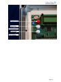
1
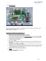
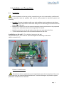
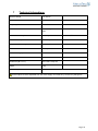
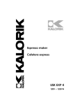
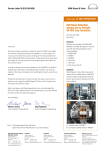
 User’s Manual
Control system MecaTecCenter
Please read this manual carefully and keep it for future use
Content:
0. Introduction
1. Warranty
2. Safety Instructions
3. Installation und Connections
3.1
Installation
3.2
Connections
3.2.1 Main cables from outside
3.2.2 Connection diagram / External interrupter with buttons (left)
3.2.3 Connection diagram / External interrupter key switch (left)
3.2.4
Cable of the motor (in the middle)
3.2.5
Power cable of the control system box (right)
3.2.6 Potential free contact connection
4. Commissioning
5. Operating
6. Repairs and Maintenance
7. Technical Specifications
8. Interface USB
9. Resetting the errors
10. Drive Mode Adjustments
Page 1 0. Introduction
The control system MecaTecCenter, an electric and electronic equipment, suitable for motordriven rolling in and out operations of pool covers.
Motor Power: up to 250 Nm.
Components and their function (picture 1)
•
•
•
•
•
•
•
•
•
•
•
-
-
Box: solid enclosure with bolted transparent covering.
In the lower enclosure part lays the fixed control system.
On the lower external enclosure wall: the main power button of the control system No.1
and three cable inlets No.2 for connections (key switch, motor cable and power cable)
Programming system and memory
Transformer for 24 VDC No.4
Cut out of 15A No.5
Electronic motherboard No.6 USB-interface - No.8 - with its own blinking LED control
lamp No.7
The USB-interface No.8 is not adapted to be connected with Mac or Linux computers.
Numbered wire termination block No.9.
Template for the correct drilling of the attachment screws in the wall (screws and dowels)
Three programming buttons No.10 with corresponding LED control lamps No.11, also
used as signal lamp in case of error report.
Battery for time- and date specification No.12
Options:
Detachable monochrome display No.3
Remote control No. 14
Page 2 The control system MecaTecCenter represents an important innovation.
During developing of the new automatic control system MecaTecCenter, we gave our attention
at first to the security and a simplified control, to guarantee an immaculate operating. The
electronic technology allows an accurate observance of the functioning and different parameters.
In fact, lot of saved data can be read by connecting a laptop to the USB connection on the board.
Furthermore, the control system can be used for all motors of different label – with built-in
encoder or without encoder.
1. Warranty
With the purchase of the control system MecaTecCenter,
you have opted for a high quality electronic control system for Pool-cover-motors.
Quality and Security
are the bases for a reliable product.
Therefore please read this notice carefully.
Electric and electronic equipments must be installed only by qualified staff. The person has to
have read and comprehended all of the security indications.
Inappropriate installation, constructional changes or non-observance of the security instructions
can cause serious injuries, such as contusions, drowning or an electric shock,
as well as mortal accidents.
Please read all the security instructions and cautionary markings carefully
MecaTec-Drive will makes with pleasure repairs or exchanges under guaranty and is
sorry for the inconveniences caused.
The control system MecaTecCenter and the periphery (remote control, power supply,
display) come with a 2-years warranty starting with the delivery date. The electronic
mother board comes with a 5-years warranty. Please consider that the warranty only
becomes effective if all of the given instructions were followed respectively.
The 5-years warranty will only be effective, when an inspection for the device and his
components has been conducted after 36 months by a specialist of the MecaTec-Drive
Company.
Page 3 Exclusion of liability
The MecaTec-Drive company is not reliable for any claims caused by use of the control system
or caused by any installation, maintain and first commissioning by an incompetent person or if
the control system was misused for inappropriate purposes. Moreover, there is no possible
commitment, if a however qualified person installs the control system improperly.
Because of modifications by components of the control system box or because of the use of
original spare parts without every previous consultation with the society MecaTec-Drive, this one
won’t assume any liability.
2. Safety Instructions and Explanations
Important Safety Instructions!
Use these instructions carefully and have a detailed look at the equipment
before any installation, operation or maintenance!
Symbols
Please respect the explanations to the following listed warnings. They are present in the whole document as
well as on the equipment itself and point out potential risks and dangers or particular information that describe
and simplify a proceeding.
Explanations to the used symbols
DANGER
WARNING
The indication DANGER refers to a potential
dangerous situation that can cause massive
injuries or even death, if not avoided.
The indication WARNING refers to a potential
danger that can cause material damage or
injuries if not avoided.
Page 4 Safety Regulations
The Control System MecatecCenter is an accredited product. It was developed under the terms
of the following norms:
•
•
•
according DIN EN 60335-1/02.2007, „Safety of electric equipment for domestic use and
similar purposes – Part 1: General claims“
according DIN EN 55014-1 and DIN EN 55014-2
Has to quit the factory in safety-related unobjectionable condition.
To guarantee this condition, handling of the equipment (transport, bearing, installation, initiation,
operating system, maintenance, shutdown) has to be done in respect of the safety regulation’s
content and the equipment‘s indicated model plates, captions and safety indications. Otherwise it
could cause personal or product-related damages.
These Safety-instructions) are valid only in the Federal Republic of Germany. Deployment in
other countries has to follow the relevant national laws. Besides the advices in these directions
of use the general safety- and accident prescriptions have to be considered.
If these indications should not be sufficient, contact with the manufacturer can be established
anytime through the stated address.
Follow imperatively the rules A, B and C listed below.
A – Referring to the electric installation (assembly, change and verification):
•
•
•
•
•
•
•
•
•
•
•
•
•
Please check the package and claim any eventual damages immediately to the forwarding agent.
Repairs should be accomplished by an expert under deployment of the original spare parts.
Otherwise, there could emerge further damage and control system breakdowns, which the
MecaTec-Drive company can no longer warrant.
The guarantee-assessed check by a MecaTec-Drive expert has to be done in due time. An
accurate check will point out any possible damage and/or abrasion.
To avoid any injuries, the equipment should be properly installed on the wall.
Do not expose any tools to water and others liquids.
The control system should be fixed at a dry, high-situated (minimum 1,5 meter above the floor) or
lockable location, inaccessible for children.
Take precautions to touch the control system only with dry hands and avoid any contact with the
motherboard, as long as this is under voltage.
In case of modification of any control system parts or use of external spare parts without prior
agreement with the MecaTec-Drive company, this one will assume no liability.
For the control system operation a 12V or 24V safety extra-low voltage line is necessary.
As safety precaution a connection has to be built between the earth conductor and an adequate
protective earth before any other connection.
For both conductive material choice and installation of the energy supply junctions the terms of
high voltage system construct with nominal voltage up to 1000V (IEC 60364 … rather DIN VDE
0100) are to be followed
The equipment has to be disengageable through an attributed separator (installed externally)
This separator has to be located near the equipment
It has to be consistent with IEC 60947-1 and IEC 60947-3
It has to disconnect all conductors
It has not to be installed inside a feeder
It has to be accessible to the user
If a riskless operating is expected not to be guaranteed anymore, the equipment has to be set off
and secured against unintended operating.
Page 5 •
•
A riskless operating is not guaranteed anymore, if:
The equipment shows visible damage
The equipment doesn’t work
After storage under damaging conditions
After difficult transport
When linked, there has to be paid attention to a spatial separation of circuits that bear danger of
contact and low voltage circuits without any danger of contact. A distance of 8 mm is
recommended.
Reassure before commissioning that the equipment shows no signs of damage. In case of doubt,
consult a certified electrician or contact the below-mentioned address.
B – Referring to the control system usage
•
•
•
•
•
•
•
•
•
•
To assure electric shock protection, the equipment has to be operating in closed condition.
If the equipment is brought immediately from a warm to a cold environment condensed moisture
can appear. Wait until a temperature adjustment has occurred. Commissioning during humid
condition signifies mortal danger.
Do not forget that certain parts in electric and electronic equipments can run on electric voltage
when being in use. Unqualified handling and non-observance of the warning notice can result in
material and physical harm.
Protect the line cord from heat, water and sharp objects.
Keep children and unauthorized persons away from the control system box.
Make sure that the swimming pool, as actual danger zone, is not used during activation of the
control system to close or to open the cover and that no person remains next to its edge. Check
imperatively that no object constricts the cover’s running-in and deployment
Before opening the equipment, there can be bared energized parts. Furthermore the junctions can
under current. Tasks on the opened equipment under voltage have only to be done by an expert,
to whom the existing dangers are familiar.
Before commissioning please check if the equipment’s operational voltage and the system voltage
correspond.
Fuse exchange and Reparation have to be done by authorized staff. Please contact the belowmentioned address.
Before cleaning: cut off the grid! Use only simple cleanser with a humid cloth. Never clean
dripping wet!
C – General Safety Notice for swimming pool use
•
•
•
The pool cover should be completely extended or removed from the water surface.
In absence of an adult, the swimming pool should be covered, even if it is only about a short
period.
Children are to be advised of the dangers concerning the control system, the pool and its cover.
Do never play next to the covered pool, nor enter the pool cover!
Page 6 3. Installation und Connections
3.1
Installation
All the installation of the box and the commissioning are to be executed by qualified staff.
For the connection work the qualified staff must be well grounded in electronic system and
electricity.
•
•
•
•
Location: Choose a closable roofed room with available electric equipment and without
humidity. It has to be maximum 40 meters away from the swimming pool and should have
direct sight of the pool.
Between the control box and the external operating switch (push buttons or key-operated
switch) use a cable that should not be longer than 15 meters.
Install the control box on the wall and not less than one meter above the floor.
Turn the three cable inlets of the connection entrances to the floor.
Installation on the wall – Fix it with the 4 screws on the wall.
The dimensions are: 219 x 140 mm. Use the template for the drilling of the holes
(drill bit + dowel: Nr.5).
Picture 2. Attachments
.
The holes for the box attachments are located directly near the screw points of the cover
and outside from the protected waterproofed zone. Therefore the degree of protection against
penetration of water won’t be lowered.
Page 7 3.2
Connections
Warning! Shut off electricity at the source before performing electrical work!
The cable connection should be only accomplished by a qualified expert with the
required knowledge.
Picture 3. Connection place
3.2.1
Main cables from outside
The cables should be connected as follows:
Loosen the cable inlets at the lower side and introduce the three cables following the plan.
Standing in front of the box you put them in this order:
1) On the left: cable of the external operating switch: push buttons or switch-Key (this box
for external interruptor is not included by the control system MecaTecCenter).
2) In the middle: cable of the motor
3) On the right: power cable of the box for controlling system with 230 V AC. For this, you
must push down with a flat screwdriver the rubber-insulated wires. The leads must be
prepared as follows:
Page 8 Make the wires free from rubber on 8 mm and connect the insulated ends to the scheduled clamp
connections in the wire termination block following the connection diagram. (Look at the picture
3.2.2.).
8 mm 100 mm Connect the grounding wire. Grounding is necessary to assure the strength class.
To keep a safe separation you must put the main power cable 230 V AC into the scheduled
screw . The separation distance has to be about 10 mm.
Page 9 3.2.2 Connection diagramm / External interruptor with buttons (left)
Terminal connections:
Nummber of connector block
Cable
Polarity
Numbering
Color codding
1
Brake 0,5mm
2
PLUS +
1
…… - blue
2
Brake 0,5mm
2
MINUS-
2
…… - black
3
Encoder 0,5mm
2
MINUS -
3
- white
4
Encoder 0,5mm
2
PLUS +
4
…… - rot
5
Encoder 0,5mm
2
Signal
5
…… - grün
6
Rollo “OPEN“
MINUS -
Customer-specific
7
Rollo “CLOSE“
PLUS +
Customer-specific
8
Rollo “STOP“
0
Customer-specific
9
Reserve
###
Customer-specific
10
Reserve
###
Customer-specific
11
Common for connector block 6,7 und 8
###
Customer-specific
12
Reserve – changeover switch (Relais)
###
Customer-specific
13
Reserve – changeover switch (Relais)
###
Customer-specific
14
Reserve – changeover switch (Relais)
###
Customer-specific
After effecting all the connections, the screws have to be tightened.
Page 10 3.2.3.
Connection diagram / External interruptor keyswitch (right)
For the key you have three wires you need to connect on the long numbered wire termination block:
you take the finest wire, the cable “0” from the jumper (done in the external interruptor box) and
connect it on the clamp No. 11. You attach both other wires to the clamps No. 6 and 7.
NOTICE: the key switch and the buttons are connections in parallel
Warning! Shut off electricity at the source before doing electrical work!
Page 11 3.2.4
Cable of the motor (in the middle)
Depending on the model you have a 5 - or 7- core cable between the control system
and the motor for the cover (conform to the provisions of the country)
Page 12 7- core cable:
The blue wire (+) and the black wire (-) (24 VDC) must be connected on the right termination
block: the black wire on the left / the blue wire on the right depending the rotation of the motor.
Five black wires – numbered from1 to 5 - must be connected to the respective clamps
according to the same numbers.
The brake cable blue 0,5mm2 and black 0,5mm2 will be connected as follows:
Number of connector block
1
2
Color coding
blue
……
Black
……
Numbering
1
2
Polarity
PLUS +
MINUS -
The encoder cable red 0,5mm2, white 0,5mm2 and green 0,5mm2 are shielded and will be
connected as follows:
Number of connector block
3
4
5
Color coding
white
……
red
……
green
……
Numbering
3
4
5
Polarity
MINUS PLUS +
ECODER SIGNAL
Page 13 3.2.5
Power cable of the control system box (right)
3-core cable as power cable:
Black wire (-)
Blue wire (+)
Grounding wire
Page 14 3.2.6
Potential free contact connection
There are two possibilities:
1) STABLE: - Pool is closed: contact 13 & 14 are on.
- Pool is open: contact 12 & 13 are on.
2) DRIVE: - Motor is not turning: contact 13 & 14 are on.
- Motor is turning: contact 12 & 13 are on.
The control box is standard equipped in Version “STABLE “. Per connecting a USB cable
between the control box and the laptop, “DRIVE “can be chosen.
The switching power of relay: max. 1A up to 24V DC and max. 1A up to 120V AC.
4.
Commissioning
4.1
Switching on
Inspect all the cables, the security system, inclusively the cable of the motor and the condition of the
cover before you switch on the control box.
No person is allowed in the swimming pool during operating of the control system box. Test the FI-Error
button!
After you switch on the red power button on the lower extern enclosure wall, at first the red LED
control lamp (No.7) - right and above the USB interface (No.8), signalize that the mother board is
under tension - and then the three red control lamps (on the left by the programming buttons) are
flashing for a short time in succession upward. About five seconds later the information “ready”
appears on the display. The control system box is ready for the commissioning.
4.2
Programming
You should regulate the data with the display.
4.2.1 Choose your language
1. Switch off the red power button on the lower extern enclosure wall.
2. Keep the open button pressed and switch on the red power button on the lower extern
enclosure wall until the information “Language, or Sprache or Langue” appears.
3. Press several times the close button until your language appears.
4. Confirm your choice by pressing the open button for one second.
Page 15 Page 16 4.2.2 Regulation of the initial and end positions
No person allowed in the swimming pool during operating of the control system box by
cover’s running-in and deployment!
At the beginning, open the cover and bring it in the initial position.
Initial position = open cover = roll the pool open= OPEN BUTTON
Page 17 Programming of the „closed position „
1
Switch on the red power button of the control box and wit until “ready” appears on the
display.
2
Press three seconds on the red programming button until the information “Programm”
appears on the display. The red LED control lamp by the programming button is flashing.
3
Now activate the external main interrupt (ir) (buttons or key switch) and bring the cover in the
begin position = roll the pool open / open position. During this opening operation the red LED
lamp near the white open button is flashing all the time.
4
If required you can adjust the position of the cover by rolling up and out. The motor must run
for at least 4 seconds in any direction.
5
Switch of the red power button of the control box.(start point open position will be
saved)
6
Switch on the red power button of the control box.
7
Press three seconds on the red programming button until the information “Programm”
appears on the display. The red LED control lamp by the programming button is flashing.
8
Now activate the external main interrupt (ir) (buttons or key switch) and bring the cover in
the final position = roll the pool closed / closed position. During this closing operation the red
LED lamp the white close button 3 is flashing all the time.
9
If required you can adjust the position of the cover by rolling up and out before you save it
and confirm the final position (closed). The motor must run for at least 4 seconds in any
direction.
10
Press the red programming button for a second. . -> „Position 1“ appears on the display,
the LED is flashing slowly.
11 Press the red programming button for a second. . -> “Position 2” appears on the display,
the LED is flashing faster.
12 Press the red programming button for a second. . -> “saved” appears on the display,
the LED is near the programming button is going out and the closed position is saved.
The opened position will be automatically saved.
Page 18 Note: to guarantee a good working of the installation it is very
important to bring the cover first in the desired open position (roll the
pool open), switch of the control box and roll the pool closed in
programming mode.
Programming of the „closed position with slow speed„
1
Switch on the red power button of the control box and wit until “ready” appears on the
display.
2
Press three seconds on the red programming button until the information “Programm”
appears on the display. The red LED control lamp by the programming button is flashing.
3
Now activate the external main interrupt (ir) (buttons or key switch) and bring the cover in the
begin position = roll the pool open / open position. During this opening operation the red LED
lamp near the white open button is flashing all the time.
4
If required you can adjust the position of the cover by rolling up and out. The motor
must run for at least 4 seconds in any direction.
5
Switch of the red power button of the control box.(start point open position will
be saved)
6
Switch on the red power button of the control box.
7
Press three seconds on the red programming button until the information
“Programm” appears on the display. The red LED control lamp by the programming
button is flashing.
8
Now activate the external main interrupt (ir) (buttons or key switch) and roll the pool
closed / closed position. During this closing operation the red LED lamp the white
close button 3 is flashing all the time.
9
Roll the pool closed until the position where the slower speed is required.
(IMPORTANT!!!! DON’T STOP THE MOTOR!!!!!
10
Press the red programming button for a second. . -> „Position 1“appears on the
display, the LED is flashing slowly. The motor is running slowly.
Page 19 11
Roll the pool closed until the position where the normal speed is required.
(IMPORTANT!!!! DON’T STOP THE MOTOR!!!!!
12 Press the red programming button for a second. . -> “Position 2” appears on the display,
the LED is flashing faster. The motor is running faster.
13
Roll the pool completely closed and stop it by pressing the close button for a second
or by the key switch.
14 Press the red programming button for a second. . -> “saved” appears on the display,
the LED is near the programming button is going out and the closed position is saved.
The opened position will be automatically saved.
Note: to guarantee a good working of the installation it is very
important to bring the cover first in the desired open position (roll the
pool open), switch of the control box and roll the pool closed in
programming mode.
Page 20 5.
Operating
The external main interruptor, that is not furnished with the control system box, must be
conformed to the requirements of the country and be equipped with either push buttons or switch
key.
5.1
Main external switch: three buttons with inching function
The cover can be activated using the push buttons with inching function. Each one corresponds
to a position (open /closed /stop). A short pressure on the scheduled button and the cover is
moving in the programmed position.
In case of danger you can press the “stop” button and the cover is stopping immediately.
You must have the pool in sight for security reasons by switching off and out.
5.2
Main external switch: switch key function
The switch key is connected parallel to the wires of the buttons and assumes the same functions.
Warning – Except France: Closing the cover can happen only under operating conditions.
Opening the cover needs to snap the key. For security reasons when closing the cover you need
to maintain the key snapped all the time until it reaches the end position. The middle position of
the key between switch off and switch on will stop the movement of the cover.
By operating you can read following other data on the display:
Below on the left: number of motor revolution
Below on the right: current consumption of the motor.
Date and time: take away the plastic clip from the battery and it will be active (right from the
display on the mother board), so you can regulate the date and the time (in development).
These indications can be very helpful for locating the disturbance source.
Red power button (power button on the control system box)
The red power button on the lower external enclosure wall serves as main switch interruptor.
For programming the language of the display it has to be switched off and on.
6.
Repairs and Maintenance
Check regularly the condition of the control system box, of the cables and of the motor. If the
system is breaking off and you notice abnormal noise or heat development, please contact our
service at the below-mentioned address.
For cleaning use only a light humid cloth.
Page 21 7
Technical Informations
Nominal voltage
110 / 230 V~
Nominal power
Max. 150
Frequency domain
48 - 62Hz
Mains fuse
800mA delay action /
250V
5 x 20 mm; IEC 60127-2
Common secondary fuse
15A delay action / 32 V
5 x 20 mm; IEC 60127-2
Environment temperature
Minus 10 up to + 60°C
Temperature for storage
-10 …+85°C
Air
20 % up to 90%
Protection category
IP54
Protection class:
I
Dimensions (B x H x T)
(240 x 465 x 100) mm
Weight
1,2kg
Motor voltage
24V~ / max. 9 A; Max. allowed output power: 200VA
No condensation allowed!
All the outputs must be separated from the mains supply circuit that is by contact very dangerous.
Page 22 8 Interface USB
Top priority for your security and your relaxation!
We have developed the control system so that the client has the advantage to use it daily quite
simply with one pressure on a button (or key switch).
For more security and efficiency, the authorized technician can obtain all the saved data of the
memory with the modern IT accessories. He can read them on the display directly at the client or
on his own connected laptop.
Connection cable USB between your laptop and the control system box for on-site support.
Insert your cable in the USB plug. The flashing LED control lamp shows successful connection.
This way offers the qualified staff the possibility to execute the same complete regulations on the
control system box. It would be better for the technician to attend a training course where he
could get suitable software and a certificate. Thus equipped he could use his computer for
complete configuration and programming of the system.
Working with laptop and USB port cable requires being on-site.
Page 23 9. Resetting the errors
In the event of an error occurring during operation, the possible cause can be identified by
reviewing the error LED indication on the display.
Generally, in case of any error occurrence the three LED near the three buttons flashes.
The fault signal is mentioned on the display.
Signal : „Key switch block“appears on the display. All three LED are flashing. Error : Key from key switch is in position open or close.
Reset : Turn the key from the key switch into position 0 or zero. „Ready“appears on the
display. Signal : „Error 2 Encoder“appears on the display. All three LED are flashing. Error : No function of the motor sensor.
Reset
: By using the software you can tick „Encoder Check“. Be careful!! The
installation could run with uncontrolled speed. Stop the motor with the key
switch. Check and inspect the motor cable and the control box.
Signal : „Motor Stop“appears on the display. All three LED are flashing
Error : The maximum current has been exceeded.
Reset
: The maximum current from the motor has been exceeded. Somewhere in
the swimming pool is a mechanical block so the motor can’t roll the pool open
any more. Solve the mechanical block in the swimming pool.
Signal : None.
Error
: The installation is running in only one direction.
Reset : Connect the key switch correct. Connect cable 6 (termination block) at 11 or
connect cable 7 (termination block) at 11. Page 24 10. Drive Mode Adjustments
The user operates the control box wit the aim to open and close the swimming pool.
You can use the control box by:
-
The buttons on the board.
-
The external key switch.
The cover can operate in 5 different EU MODE:
EU 1 (Standard)
Opening and Closing of the cover occurs automatically by pressing the open-or close button in
the control box for 1 second or by operating the key switch. (Pulse control)
Stopping the movement of the cover is achieved by operating the key switch in “0” or by pressing
the open- or close button in the control box for 1 second.
Mode EU 2 (France)
Opening of the cover occurs automatically by pressing the open button in the control box for 1
second or by operating the key switch. (Pulse control)
Closing of the cover occurs as long as the close button in the control box is being pressed or the
key switch is operated. (Holding control).
Stopping the movement of the cover in open direction is achieved by operating the open button
in the control box for 1 second or by operating the key switch. (Pulse control)
Stopping the movement of the cover in close direction is achieved by releasing the close button
in the control box or by releasing the key switch. (Holding control).
Page 25 MODE EU 3 (Holding control in both directions)
Opening and Closing of the cover occurs as long as the open- or close button in the control box
are pressed or the key switch is operated. (Holding control).
Stopping the movement of the cover in open and close direction is achieved by releasing the
open- or close button in the control box or by releasing the key switch. (Holding control).
MODE EU 4 (Pulse control)
Opening and Closing of the cover occurs automatically by pressing the open-or close button in
the control box for 1 second or by operating the key switch (without 0 position). (Pulse control)
Stopping the movement of the cover is achieved by operating the key switch or by pressing the
open- or close button in the control box for 1 second.
MODE EU 5
Is being used for pulse switch with remote.
-
Press once = Roll the pool open.
Press once = Stop.
Press once = Roll the pool closed.
Press once = Stop.
Press once = Roll the pool open.
Page 26