1
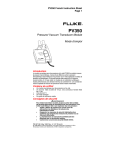
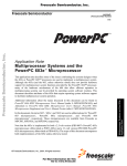
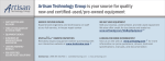
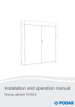
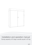
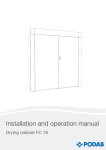
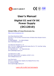
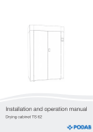
PV350 English Instruction Sheet
Page 1
®
PV350
Pressure/ Vacuum Transducer Module
METRIC
ENGLISH
PV 500
PRESSURE
Instruction Sheet
ZE
MODULE
/ VACUUM
cmHg ¥ inHg
kPa ¥ psi
OFF
Introduction
The PV350 Pressure/Vacuum Transducer Module (the module)
measures gauge pressure; the difference between atmospheric
(barometric) pressure and the pressure (or vacuum) applied to the
pressure port on the transducer. It then converts that measurement to 1
mV dc per unit. A module and a high-performance digital multimeter
(DMM) with min/max function become a datalogger capable of measuring
peak high and peak low.
Box Contents
•
•
•
•
•
Pressure/Vacuum Transducer Module
1/4 -inch male flare to 1/4-inch female pipe thread connector
9V battery
Storage tray
Instruction Sheet, Quick Reference guide, and warranty card
Safety Information
WARNING
To avoid eye injury, always wear approved safety glasses
when working with this instrument.
To avoid injury from pressure explosion:
•
Be sure that pressure is removed before
disconnecting any hoses or tubing from the PV350
transducer.
•
Follow accepted safety procedures for systems on
which pressure or vacuum measurements are made.
•
Make sure the PV350 is serviced by a qualified
technician.
Safety Standards: Complies with test pressure requirements of
ANSI/ISA S82.03-1988, Protection Class III per IEC 1010-11990, Annex H.
PN 926873 May 1992 Rev. 4, 9/97
© 1999 Fluke Corporation, All rights reserved. Printed in U.S.A.
All product names are trademarks of their respective companies.
PV350 English Instruction Sheet
Page 2
This module has been designed and tested in accordance with
IEC Publications 348 and 1010. To ensure that the module is
used safely, follow all safety and operating instructions in this
Instruction Sheet. If the module is not used as described in this
Instruction Sheet, the safety features of the module might be
impaire
Do not use the module if the module or fittings look damaged, or
if you suspect that the module is not operating properly.
This symbol on the module indicates that an operator should
refer to an explanation in the instruction sheet.
Follow accepted safety procedures for the systems on which
pressure or vacuum measurements are being made.
Materials Compatibility
The PV350 is compatible with industrial gases and liquids that are
compatible with 316 stainless steel. To determine the compatibility of a
liquid or gas, refer to the manufacturer’s specifications. When making
measurements on more than one type of pressure system, make sure the
fluids or gases in those systems are compatible. If they are not,
contamination or damage to the system being measured may result.
Cleaning
Clean the module using a soft cloth and mild soap and water. Do not
immerse the PV350 in liquids.
Clean the transducer and connectors after each use with a cleaner
appropriate for the liquid or gas connected during measurement. Refer to
the manufacturer’s instructions for the proper cleaning material.
Measuring Pressure and Vacuum
Caution
The sensor diaphragm can be damaged by solid or sharp
objects. Never insert any object into the inlet port.
Clean the sensor immediately after use with appropriate
solvents (refer to the solvent manufacturer’s instructions).
NOTE
Fluke recommends that teflon sealing tape (or its equivalent)
be used in fitting threads to ensure good seals between the
PV350 and any hoses or fittings.
1.
Plug the PV350 into the DMM (red polarity dot to volts input) and set
the multimeter to mV dc.
2.
Check the battery voltage (see Testing the Battery).
3.
Press the English/Metric button to select the desired units.
4.
Slide the switch to the desired setting.
5.
Before applying pressure, zero the module by turning the ZERO
potentiometer until the DMM displays zero. (Zero on the range you
will be using and rezero the DMM whenever the scale is changed.)
PV350 English Instruction Sheet
Page 3
87
TRUE
RMS
METER
MULTI
mV
HOLD
H
E
RANG
MIN
MAX
Hz
REL
PEAK
MIN
MAX
mA
A
mV
µA
V
Module
F
L
U
K
E
g
H
.i
n
s
i
g
.p
a
F
F
O
k
P
M M
A
H
COM
mA
c
m
V
E E
T
P
RT
R
IC IC
V
3
5
0
OFF
P
R
E
S
S
U
R
E
V
A
C
U
M
N
M
O
D
U
L
E
V
A
A
400m D
FUSE
X
MA
10A D
FUSE
!
To
pressure/vacuum
input
Sensor
Figure 1. Operation
NOTE
The Relative or Zero function on your DMM (if available) can
be used instead of the ZERO potentiometer to zero the meter.
Refer to the multimeter’s user manual for instructions on using
this function. Zeroing the meter does not affect the module’s
specified accuracy.
6.
Apply pressure/vacuum to the PV350 and read the DMM display.
•
•
When measuring pressure, if the DMM displays OL, switch the
multimeter range from millivolts to dc volts. Increasing the
range to dc volts moves the decimal position three places to
the left (500 psi displays as 0.500V).
When measuring vacuum the DMM displays a minus sign.
Testing the Battery
1.
Turn the DMM and the module OFF and connect the PV350 to the
DMM.
2.
Turn the DMM on and set the DMM to the mV dc range.
3.
If the DMM displays less than 100 mV, replace the battery.
How to Replace the Battery
WARNING
TO AVOID ELECTRICAL SHOCK, DISCONNECT THE
MODULE FROM ALL DEVICES BEFORE OPENING THE
CASE. BE SURE TO COMPLETELY REASSEMBLE THE
MODULE BEFORE ATTEMPTING TO USE IT.
PV350 English Instruction Sheet
Page 4
Battery
Figure 2. Battery Replacement
1.
Turn the module OFF and unplug it from the DMM.
2.
Remove the screw from the back of the module, separate the case,
and replace the battery.
3.
To reassemble, line up the holes in the case with the metric/english
switch and zero knob. Then snap the two halves together. Reinstall
the screw.
Typical Applications
88
AUTOMOTIVE TESTER
DC
mV
20
2
4
6
8
3
2
4
6
8
4
4000
mV
ZERO
MIN MAX
SMOOTH
RANGE
HOLD
RPM
% DUTY
Hz
ms-PULSE
H
ALERT
_
+ TRIGGER
mV
mA
A
V
RPM
mA
A
V
OFF
A
mA
10A MAX
FUSED
A
COM
400mA MAX
FUSED
V
RPM
1000V MAX
!
METRIC
Z
ENGLISH
PV500 PRESSURE
/ VACUUM MODULE
cmHg ¥ inHg
kPa ¥ psi
OFF
Pressure for HVAC/R Super Heat Measurements
PV350 English Instruction Sheet
Page 5
88
AUTOMOTIVE TESTER
RANGE
DC
mV
20
2
4
6
8
3
2
4
6
8
4
4000
mV
ZERO
MIN MAX
SMOOTH
RANGE
HOLD
RPM
% DUTY
Hz
ms-PULSE
H
ALERT
_
+ TRIGGER
mV
mA
A
V
RPM
mA
A
V
OFF
A
mA
10A MAX
FUSED
A
COM
400mA MAX
FUSED
V
RPM
1000V MAX
!
METRIC
Z
ENGLISH
PV500 PRESSURE
/ VACUUM MODULE
cmHg ¥ inHg
kPa ¥ psi
OFF
Measure Pneumatic Pressures
psi = inches of H2O x (3.6127 x 10-2)
-3
psi = mm of H2O x (1.4223 x 10 )
-3
inches of H2O = psi x 27.68
mm of H2O = psi x 703.1
psi = cm of H2O x (14.223 x 10 )
cm of H2O = psi x 70.3
psi = bar x (14.503)
bar = psi x 0.0689
2
-3
lbs/ft2 = psi x 144
psi = lbs/ft x (6.9444 x 10 )
psi = mbar x (1.4503 x 10⁻²)
mbar = psi x (68.9513)
-4
psi = Pascals x (1.4503 x 10 )
Pascals = psi x (6.895 x 10³)
All H2O conversion factors are @ 4°C
Conversion Factors
How to Calibrate the PV350
Calibrate the PV350 yearly to ensure that it meets its performance
specifications.
Table 1. Recommended Equipment
Instrument
Precision
Pressure
Reference
Pressure
Source
DMM
1.
Minimum Specification
500 psi, 0.25% of reading
accuracy
Nitrogen gas bottle with
pressure regulator, >750
psi
0 to 500 mV (minimum)
with 0.1 mV resolution 10
MΩ input impedance
Recommended Model
Crystal Engineering
inHg/PSIG Multical or
equivalent
Tescom pressure
regulator Model 442214-24 1V
Fluke 45 or equivalent
Allow the PV350 to stabilize at room temperature, away from drafts,
for at least 30 minutes. Turn on the DMM and, if required by its
operating instructions, allow it to warm up as indicated.
PV350 English Instruction Sheet
Page 6
2.
Connect the pressure regulator to the nitrogen bottle and the
reference pressure gauge to the pressure regulator. The nitrogen
bottle must have >750 psi.
3.
Verify the condition of the battery and if necessary, replace the
battery. (Refer to Figure 2.)
4.
Remove the top cover of the module and connect it to the mV input
of the DMM. Set the scale to measure 500 mV (0.1 mV resolution).
5.
Turn on the PV350 and allow it to warm up for two minutes.
6.
Set the PV350 to the psi range.
7.
Center the ZERO potentiometer,R3 (see Figure 3). Remove the
knob from R3 and insert it into R4 (the coarse zero adjustment).
With no pressure applied, set the reading to 0V ±0.0003V. Insert the
knob back into R3, and adjust the final reading to 0.0000V,
±0.0001V.
R3
R4
R16
Figure 3. Calibration Adjustment Points
8.
Connect the sensor to the pressure reference and nitrogen bottle
pressure calibration system.
9.
Adjust the pressure regulator to about 250 psi.The readings on the
reference pressure gauge and the reading from the PV350 should
agree within ±0.1% of the point, ±-0.3 psi: approximately ±0.0006V
or ±0.6 psi. Adjust R16 as necessary.
10. Adjust the pressure regulator to about 350 psi. The readings on the
reference pressure gauge and the PV350 should agree within
±0.1% of the point, ±0.3 psi: approximately ±0.0007V or ±0.7 psi. If
necessary, adjust R16 to bring the reading into specification and
recheck the 250 psi point. It may be necessary to repeat steps 9 and
10 until both points are within specification.
11. Reduce pressure to zero and switch the module OFF.
How to Verify Calibration
1.
Connect the sensor (transducer) to a pressure calibration standard,
and plug the module into the DMM.
2.
Be sure the system is vented, then zero the module.
3.
Enter the pressure settings shown in Table 2 and check for the
indicated readings
PV350 English Instruction Sheet
Page 7
NOTE
To save time, verify each reading (psi, kPa, cm of Hg, and
inches of Hg) before changing the pressure setting.
Table 2. Readings in mV
Setting
(in psi)
0
125
350
psi*
-0.1 to +0.1
123.4 to126.6
346.2 to 353.8
kPa
-2.1 to +2.1
-2386.8 to
2439.2
cm-Hg
-1.6 to +1.6
-1790.4 to
1829.7
Inches-Hg
-0.6 to +0.6
-704.9 to
720.3
*Zero the module before making psi measurements. Do not re-zero when
switching to check kPa, cm-Hg, or in-Hg readings.
Specifications
The following specifications apply at 23 ±5°C for 1 year after calibration
when the module is zeroed prior to each measurement.
Pressure
Range
to 350 psig
(3.447 to 2413 kPa)
350 to 500 psig
(2413 to 3447 kPa)
Accuracy
±1% of reading ±0.3 psig
(±1% ±2.1 kPa)
±5% of reading ±1 psig typical
(±5% ±7.0 kPa)
Vacuum
Range
0 to 29.9 in-Hg
(0 to 76 cm-Hg)
Accuracy
±1% of reading ±0.5 in-Hg
(±1% of reading ±1.3 cm-Hg)
Output: 1 mV per unit (psi, kPa, cm-Hg or in-Hg)
Resolution: 0.1 psi/in-Hg in mV range, 1 psi/in-Hg in Volt range with 3
1/2- or 4-digit meters.
RFI Specification: Typically < 1% error from 14 kHz to 30 MHz at 1 V/M.
Meter Input Impedance: 10 MΩ (For input impedance of 1Mý, add 0.5%
to basic accuracy specification.)
Maximum working pressure: 500 psi.
Burst Pressure: 1000 psi.
Storage Temperature: -51 to 71⋅C
PV350 English Instruction Sheet
Page 8
Operating Environment
Temperature
Humidity
-10 to 10⋅C
10 to 30 ⋅C
30 to 40 ⋅C
40 to 50 ⋅C
50 to 55 ⋅C
Uncontrolled Humidity
0 to 95% Relative Humidity
0 to 75% Relative Humidity
0 to 45% Relative Humidity
0 to 35% Relative Humidity
Temperature Derating: (Add to Basic Accuracy Specification.
°C = ambient temperature)
Temperature Range
28⋅ to 55⋅C
18⋅ to 28⋅C
0⋅ to 18⋅C
-10⋅ to 0⋅C
Derating
0.016% x (⋅C - 28)
No derating
0.048% x (18 - ⋅C)
0.264% x (9⋅ - ⋅C)
General
Weight: 12 oz, (336 grams)
Battery: Standard 9V battery (NEDA #1604, 6F22, 006P)
Battery Life: 300 hours (typical) for Carbon-zinc 400 hour (typical) for
Alkaline
Vibration: 3g @ 55 Hz
Shock: 1 meter drop
Electrical Cable: Black PVC, will withstand up to 105⋅C
Cable Length: 8 feet
Pressure Port Connection: 1/4 inch NPT
Connector: Brass 1/4-in male flare to1/4-in female pipe thread
Table 3. List of Replaceable Parts
JF PN
446823
650903
919790
913207
926873
926881
927009
Description
Battery, Primary, 9V, 0-15 mA
Case Bottom, PV350
Case Top, PV350
Fitting, BR, SAE, 45, 1/4 FP
PV350 Instruction Sheet
PV350 Quick Reference Guide
Replacement Cable Assembly
For application or operation assistance or information on Fluke
products, call:
800-44-FLUKE (800-443-5853) in U.S.A. and Canada
31 40 723-220 in Europe
206-356-5500 from other countries
The phone number for replacement parts is 1-800-526-4731
Fluke Corporation
P.O. Box 9090
Everett, WA
98206-9090
Fluke Europe B.V.
P.O. Box 1186
5602 B.D.
Eindhoven
The Netherlands