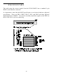
1
PCM-COM 422 & 485
ComputerBoards, Inc.
Revision 3
April 1999
LIFETIME PRODUCT WARRANTY
Every ComputerBoards, Inc. product is warranted against defects in materials or workmanship
for the life of the product, to the original purchaser. Any products found to be defective in
material or workmanship will be repaired or replaced promptly.
LIFETIME HARSH ENVIRONMENT WARRANTYTM
Any ComputerBoards, Inc. product which is damaged due to misuse may be replaced for only
50% of the current price. I/O boards face some harsh environments, some harsher that the
boards are designed to withstand. When that happens, just return the board with an order for its
replacement at only 50% of the list price. ComputerBoards does not need to profit from your
misfortune. By the way, we will honor this warranty for any other manufacture’s board that we
have a replacement for!
30 DAY MONEY-BACK GUARANTEE
Any ComputerBoards, Inc. product may be returned within 30 days of purchase for a full
refund of the price paid for the product being returned. If you are not satisfied, or chose the
wrong product by mistake, you do not have to keep it. Please call for a RMA number first. No
credits or returns accepted without a copy of the original invoice. Some software products are
subject to a repackaging fee.
These warranties are in lieu of all other warranties, expressed or implied, including any implied warranty
of merchantability or fitness for a particular application. The remedies provided herein are the buyer’s
sole and exclusive remedies.
Neither ComputerBoards, Inc., nor its employees shall be liable for any direct or indirect, special,
incidental or consequential damage arising from the use of its products, even if ComputerBoards has
been notified in advance of the possibility of such damages.
Notice
ComputerBoards, Inc. does not authorize any ComputerBoards, Inc.
product for use in life support systems and/or devices without the
written approval of the President of ComputerBoards, Inc. Life support
devices/systems are devices or systems which, a) are intended for
surgical implantation into the body, or b) support or sustain life and
whose failure to perform can be reasonably expected to result in injury.
ComputerBoards, Inc. products are not designed with the components
required, and are not subject to the testing required to ensure a level of
reliability suitable for the treatment and diagnosis of people.
(C) Copyright 1997 ComputerBoards, Inc.
No part of this manual may be reproduced without written permission from ComputerBoards, Inc.
...........................
INTRODUCTION
..........................
INSTALLATION
WINDOWS 95 . . . . . . . . . . . . . . . . . . . . . . . . . . . . .
DOS AND/OR WINDOWS 3.1 . . . . . . . . . . . . . . . . . .
........................
RUNNING INSTACAL
INSTALLING AND LAUNCHING INSTACALTM . . . .
TESTING THE INSTALLATION . . . . . . . . . . . . . . . .
............................
CONNECTIONS
PCM-C422/232 CABLE . . . . . . . . . . . . . . . . . . . . . . .
PCM-C422/422 CABLE . . . . . . . . . . . . . . . . . . . . . . .
PCM-COM485 CONNECTOR . . . . . . . . . . . . . . . . . .
.............
PROGRAMMING & APPLICATIONS
PROGRAMMING LANGUAGES & APPLICATIONS . .
...................
CALIBRATION & SERVICE
.....
I/O ADDRESS MAP & REGISTER FUNCTIONS
CONTROL REGISTERS . . . . . . . . . . . . . . . . . . . . . .
BASE +7 SIGNAL CONFIGURATION REGISTER . . . .
PCM-COM422 SIGNAL CONFIGURATION . . . . . . . .
MODESEL RS232/RS422 . . . . . . . . . . . . . . . . . . . . .
CNTL_EN CONTROL ENABLE/DISABLE . . . . . . . . .
.....................
PCM-COM422 SPECIFICS
.....................
PCM-COM485 SPECIFICS
TRANSMITTER/RECEIVER ENABLE REGISTER . . . .
BASE +7 - CONTROL REGISTER (Byte, WRITE ONLY)
...........................
SPECIFICATIONS
........................
OLDER COMPUTERS
i
........... 1
........... 2
........... 2
........... 3
........... 6
........... 6
........... 9
........... 9
. . . . . . . . . . 10
. . . . . . . . . . 11
. . . . . . . . . . 12
. . . . . . . . . . 13
. . . . . . . . . . 13
. . . . . . . . . . 14
. . . . . . . . . . 15
. . . . . . . . . . 15
. . . . . . . . . . 16
. . . . . . . . . . 16
. . . . . . . . . . 16
. . . . . . . . . . 16
. . . . . . . . . . 17
. . . . . . . . . . 17
. . . . . . . . . . 19
. . . . . . . . . . 19
. . . . . . . . . . 20
. . . . . . . . . . 21
INTRODUCTION
The PCM-COM422 and PCM-COM485 are serial communications boards for IBM
PC compatible computers with PCMCIA type slots. The heart of the board is a 16550
UART which is configured to be compatible with all DOS and Windows COM port
drivers and software. Customers familiar with the CIO-COM422 and CIO-COM485
will notice immediately the similarity in register structure and function between the
PCMCIA board and the ISA bus boards.
Each of the boards is based on the 16550 UART. This UART has a built in FIFO
memory and allows data transfer rates consistently faster than boards using the more
commonly used 16450 chip. Sustained data transfer rates of 115 Kbaud are achievable
with any of the PCM-COM series boards.
The serial ports can be configured as COM1: COM2:, COM3: or COM4: and support
a wide variety of serial transfer modes including using 5, 6, 7, or 8 data bits, with odd,
even, or no parity, and 0, 1 or 2 stop bits.
The PCM-COM485 transmitter may be enabled or disabled via software and allows
the board to operate on a 2-wire network.
The PCM-COM485, single port RS-485 interface uses the PCM-C485/485 cable. The
PCM-COM422 provides a single port of either RS-232 or RS-422. For RS-232 operation use PCM-C422/232 cable, for RS-422 use PCM-C422/422 cable
1
INSTALLATION
WINDOWS 95
Your PCM-COM is completely plug and play. There are no switches or jumpers to set
prior to installation in your computer. Simply follow the steps shown below to install
your PCM- hardware.
1.
Start Windows 95
2.
Insert the card into a free PC Card/PCMCIA type II or III slot. You do not
have to turn the computer off. The system is designed for power on installation.
3.
Windows 95 will automatically detect the card. If you have previously
installed a PCM data acquisition /control card, its driver set may include your
new card. If so, you will hear the insertion tone, the “New Hardware Found”
dialog box will disappear and you can proceed to the section titled “Running
InstaCal”.
4.
If the drivers are not already installed on your PC, depending on the version
of Windows 95 you have (there are currently two), you will either see a New
Hardware Found dialog box or a Update Device Driver Wizard box.
If you see the New Hardware Found dialog box follow these instructions (Windows
95A). If you receive the Update Device Drive Wizard box, skip to the section on the
following page titled Windows 95B.
Windows 95A (New Hardware Found dialog box)
5.
Select the default radio button labeled "Driver from disk provided by hardware manufacturer".
Click OK.
6.
When prompted by the “Install From Disk” dialog box, insert the disk
labeled InstaCal.
Click OK.
7.
The appropriate driver should be automatically selected. However, if presented with a list, select the PCM card you are currently installing.
Click OK.
2
8.
An insertion tone should be heard and the card should now appear under the
Device Manager's list at node “DAS Component”. Please proceed to the section titled InstaCAL.
Windows 95B (Update Device Driver Wizard)
5.
Insert the InstaCal disk, then Click on Next to let the system look for an
updated driver.
6.
When the driver for your card is found, Click on Finish to return to Windows
95 desktop.
7.
An insertion tone should be heard and the card should now appear under the
Device Manager's list at node “DAS Component”.
8.
Please proceed to the section titled InstaCAL.
If no New Hardware Found or Update Device Driver dialog box appears, check that
your computer’s 32-bit PCMCIA drivers are enabled. This can be checked using the
following Windows 95 sequence. Right Click on My Computer, select Properties
then Performance. It should read 32-bit. If not, enable 32-bit, shut down your computer and try the above procedure again.
DOS AND/OR WINDOWS 3.1
Most users are now installing boards on systems with at least Windows 95 operating
systems. However, if you wish to install the PCM-COM in a machine running Windows 3.1 and/or DOS, you will need to use the DOS based Card & Socket services
routine. This is included with most newer computers. However, if you need to purchase these routines, they are available.
After you have installed all the software using the automated install program, please
run InstaCalTM.
CARD & SOCKET SERVICES
The following section describes Card & Socket Services and should help you determine whether or not you need to install CSS.
Card and socket services for your PCM card are on a disk labeled PCM Board Card &
Socket Services. We will refer to Card & Socket Services as ‘CSS’ for the remainder
of this manual. The software from that disk should be installed if you do not already
have CSS support on your PC.
3
What is CSS?
CSS is a program that communicates with your computers PCMCIA interface controller and configures it. The PCMCIA interface is configurable, unlike the standard ISA
bus you may be familiar with. If you plug a PCMCIA board into a PCMCIA slot and
have not yet run CSS, you will have no access to the functions of that PCMCIA board.
Does CSS use system resources?
Yes. The CardSoft Card and Socket Services device drivers which are installed in
your CONFIG.SYS use about 61K of memory. These files can be installed DEVICEHIGH.
The CBCLIENT.EXE installed in your AUTOEXEC.BAT uses about 10 K of memory. The CBCLIENT.EXE program is a TSR (Terminate and Stay Resident). You
may modify the program line to LOADHIGH the TSR. We have tested it both high
and low with and without Windows and a variety of other applications. We believe it
is a safe TSR that will not cause any system problems.
How do I know CSS is installed and running?
There is a simple test. Just plug in your PCM-card. If CSS is installed and working
the computer will beep. You can remove and replace your PCM-card as often as you
like and need not power down to do so. The computer should beep each time you
insert the PCM-card.
What about CSS for multiple PCM boards?
Once the current version of CSS is installed, CSS is installed for all PCM boards
included in that version of CSS. As new PCM boards become available, they will be
added to the CSS and you will want to always have the most recent version of
CBCLIENT.EXE installed in the C:\CB directory. Let the installation software do
this for you.
You can run multiple PCMCIA boards with the CBCLIENT.EXE CSS, and, if you
have another CLIENT program running for other PCMCIA boards, it will not
interfere.
If you decide to install CSS
When you run the InstaCal installation described in the next section, you will be
prompted to indicate whether or not to install CSS. Respond ‘yes.’ After installation
of InstaCal and the Universal Library (if ordered) the CSS disk will be requested.
Insert the CSS disk and accept the defaults when prompted if possible.
4
INSTACAL
Install the InstaCalTM software
Windows (in its various forms) and DOS users install the program by running the
INSTALL.EXE program supplied on your InstaCAL disk. (Some versions of InstaCAL will include a file named SETUP.EXE. If you are running from Windows 3.x,
Windows 95 or higher, and your InstaCAL disk contains SETUP.EXE, run it rather
than INSTALL.EXE.) You will then be prompted for some information. Follow the
instructions and if possible accept the defaults. If this is your first installation, we urge
you to accept the defaults. It will be easier to assist you in the event of trouble with
default settings.
The installation routines will create all required folders/directories and unpack the
various pieces of compressed software. Simply follow the on-screen instructions.
Remember where the InstaCAL files are placed, as you will need to access them in the
next step (the default location is on your main hard drive in a directory or folder
named C:\CB\).
If you have purchased the Universal Library programmers library, the installation program will install all the software required to run the PCMCIA board as well as the
UniversalLibrary.
Launching InstaCALTM
Prior to starting InstaCAL, reboot your computer so the various changes made to your
start up files are active.
From the DOS prompt you may start InstaCAL by simply typing: InstaCal and hitting
enter.
From Window 3.x, use the file manager to find InstaCAL.exe. It should be on your
main hard drive in a directory called C:\CB. (if C:\ is your main hard drive). To
launch InstaCAL, simply double click on the file InstaCAL.exe. (You may also launch
InstaCAL use the FILE menu, select RUN, type InstaCAL and click on OK.)
From Win95, use "Start: Run" , type InstaCAL at the prompt and click OK.
Using InstaCalTM
InstaCal is the Installation, Calibration and Test software supplied with your I/O
board. After installing InstaCal you should restart your computer to take advantage of
changes made to the AUTOEXEC and CONFIG files.
If you have a PCM board installed in a PCM slot in your computer, the first message
InstaCal displays is
Card PCM-COM found in slot #.
5
A dialog box opens allowing you the choice to install, or not install the software configuration for your PCM-card. Install the card by choosing yes.
Two additional dialog boxes will open. One shows the boards currently installed in
your configuration file, the second allows you to choose a board number to assign to
the PCM-card you are currently installing. If this is your first installation simply hit
enter to accept the default of BOARD 0.
If you have other boards already installed, choose a board number not currently in use.
InstaCAL will do the rest of the initial installation of your PCM board selecting
addresses and other system resource settings which are not your choice to select.
InstaCal help is available by pressing the F1 function key. Most of InstaCal is intuitively obvious and for that reason there is no user's manual for InstaCal.
Once done, exit InstaCal. This will update and save the configuration file, CBI.CFG
in the C:\CB directory.
InstaCal selects and sets the I/O address and interrupt level from the range of available
options. The address and other information is stored in the configuration file
CB.CFG. This file is accessed by the Universal Library for programmers. Note also
that the Universal Library is the I/O board interface for packaged applications such as
Labtech Notebook and HP-VEE, therefore the InstaCal settings must be made in order
for these and other applications to run.
The board’s base address is also stored in the system software. Once InstaCal installation software is run, other programming methods such as direct IN and OUT statements can write and read the PCM-card registers by reference to the base address and
the offset from base address corresponding to the chart of registers located elsewhere
in this manual.
But a word of warning is in order here. Direct writes to the addresses simply by reference to the base address of the PCM-card I/O registers is not advised. Since the
addresses assigned by the PCM plug & play software are not under your control, there
is no way to guarantee that your program will run in any other computer.
Not only that, but if you remove and then reinstall your PCM board, the plug & play
software may not choose the same address during the second or subsequent installations. It is best to use a library such as Universal Library or a program such as HPVEE to make measurements with your PCM-card.
6
TESTING THE INSTALLATION
After you have run the install program and set your base address with InstaCal, it is
time to test the installation. The following section describes the InstaCal procedure to
test that your board is properly installed.
With InstaCal running, choose the TEST item on the main menu.
a.
Select the board you just installed
b.
If the choice “Internal Test” is available, then select Internal Test. If not, proceed to v. below.
c.
The internal control registers of the board will then be tested. If this test is
successful, your board is installed correctly.
d.
If the Internal Test is completed successfully, you may want to check that the
I/O pins are working correctly. To check this select External Test and follow
the instruction provided. This will require you to use the shorting wires supplied with the board to connect inputs to outputs for I/O testing. Some external tests may require an external voltage source and ohmmeter. All required
equipment and connections will be listed by InstaCAL.
e.
If the “I/O Test Menu” lists the option “Plot”, the select it and make then
connections as shown to test your card
7
RUNNING INSTACAL
InstaCal is the Installation, Calibration and Test software supplied with all I/O boards.
InstaCal must be run to set the base address and interrupt of the PCM-COM. In addition to procedures for testing of your PCM-COM, InstaCal creates a configuration file
which is used by the UniversalLibrary.
INSTALLING AND LAUNCHING INSTACALTM
From WINDOWS 95
Place the InstaCal disk in your floppy drive. Select START, then RUN, then enter
A:\Setup and hit return. InstaCal will then be installed on your hard disk.
To run InstaCal in Windows 95 you may either use the START, RUN, procedure then
type InstaCal and hit return. You may also go to your My Computer Icon, select the
drive that INSTACAL was installed on, select the \CB directory, find InstaCal.exe and
double click on it. (you may also wish to create an InstaCal shortcut using the Create
Shortcut function).
InstaCal will automatically detect your PCM-COM board. You may now choose to
change or accept the defaults for the various options. Once done, exit InstaCal. This
will update and save the configuration file, CBI.CFG in the C:\CB directory. Your
installation is now complete. You may now want to try the TEST function built into
Instacal to assure your board is properly installed and functioning normally.
Users of the PCM-COM422 and PCM-COM485 should refer to the sections later in
this manual that deal with the specific operation consideration of each of the boards.
From DOS or Windows 3.x
The software is easy to install. Among the disks supplied with your PCM-COM is one
labeled InstaCal. On this disk is a program, INSTALL.EXE which will install all the
software required to run the PCM-COM as well as UniversalLibrary programming
language support, if you choose to order this option.
Insert the disk labeled InstaCal into a floppy drive and type (drive A: is used in this
example):
A:INSTALL
8
You will be prompted for some information. Please follow the instructions and if
possible accept the defaults. If this is your first installation, we urge you to accept
the defaults. It will be easier to assist you in the event of trouble if you accept the
defaults.
Install does these things (explanation presumes you accept defaults).
1.
2.
Creates directories:
C:\CB
C:\CARDSOFT
Adds the directory:
;C:\CB
and numerous directories SUB to these
to the PATH statement in your AUTOEXEC.BAT
file.
3.
Adds these lines to CONFIG.SYS (if installing CSS):
DEVICE=C:\CARDSOFT\SS??????.EXE
DEVICE=C:\CARDSOFT\CS.EXE
DEVICE=C:\CARDID.EXE
DEVICE=C:\CSALLOC.EXE C:\CARDSOFT\CSALLOC.INI
4.
Adds these lines to AUTOEXEC.BAT:
SET CBDIREC=C:\CB
C:\CB\CBCLIENT.EXE
5.
Copies these files into the C:\CB directory:
INSTACAL.EXE Installation & calibration program and related help files.
CB.CFG I/O Board address, interrupt and configuration file.
CBCLIENT.EXE PCMCIA Card & Socket Services
UniversalLibrary Programming language support in sub directories.
CBW.DLL
Windows language DLL
CBUL.386
Windows language VxD
If you are using DOS or Windows 3.x, you may run InstaCAL simply by typing
INSTACAL and hitting return (Because the directory C:\CB was added to your PATH
statement, you can run InstaCal from any directory).
From Windows 3.x, use the RUN command, and RUN C:\CB\Instacal.exe (assumes
you loaded your software onto drive C:. If not substitute the correct drive letter).
InstaCal will automatically detect your PCM-COM board and install it at an appropriate address.
9
If you are not running Win 95, you may now choose to change or accept the defaults
for the various options. (In Windows 95 the address/interrupt is set by the Windows
95 operating system). Once done, exit InstaCal. This will update and save the configuration file, CBI.CFG in the C:\CB directory.
COM PORT
In DOS/Win 3.x, the PCM-COM may be set to operate at any one of the four COM
ports, COM1, COM2, COM3 or COM4.
COM Port
COM 1
COM 2
COM 3
COM 4
HEX RANGE
3F8-3FF
2F8-2FF
3E8-3EF
2E8-2EF
INTERRUPT
4
3
4 or
3 or
CSS I/O ADDRESS EXCEPTIONS
CSS examines your computer's I/O address space looking for addresses which are
available.
IF AN ADDRESS RESERRVED BY CSS CONFLICTS WITH THE BASE
ADDRESS YOU HAVE CHOSEN, INSTACAL WILL ADVISE YOU.
When you exit the PCM-COM setup screen in InstaCal, InstaCal attempts to initialize
the TSR CBCLIENT with the setup information you have just provided. CSS checks
for address conflicts. If it detects one, InstaCal will advise that you must choose a different address. You will not be able to exit the PCM-COM setup screen until you do
choose a different address, and one which does not conflict with addresses reserved by
CSS.
10
INTERRUPT LEVEL
The PCM-COM uses one of the computer's hardware interrupt lines. The PCM-COM
may use interrupts 2-5 through 15. We recommend you use the standard interrupts
allotted to COM ports. InstaCal will allow you to override the recommended interrupt
and select another.
You must choose an interrupt level for the PCM-COM from the available interrupts in
your computer. The table below shows typical interrupt level use in a personal computer. Please add those interrupts you have assigned to other boards, and note your
selection for the PCM-COM.
IRQ #
NMI
IRQ 0
IRQ 1
IRQ 2
IRQ 3
IRQ 4
IRQ 5
FUNCTION
Parity
Timer
Keyboard
Available
Interrupt 8-15 (AT)
COM 2
COM 1
LPT2:
IRQ 6
IRQ 7
Floppy Disk
LPT1: (PRN)
(XT)
IRQ#
IRQ 8
IRQ 9
IRQ 10
IRQ 11
FUNCTION
Real Time Cock
Re-directed to IRQ2 (AT)
Available
Available
IRQ 12
IRQ 13
IRQ 14
Available
Numeric CoProcessor
Hard Disk
IRQ 15
Available
When you insert the PCM-COM into the PCMCIA slot on your computer, you should
hear a pleasant beep beep. This is CSS' way of informing you that the board PCMCOM is fully inserted in the correct orientation and that CSS recognizes the PCMCOM identification code.
If you hear a lower, less pleasant tone, somewhat of a baaaaap, then there is something wrong with the installation.
TESTING THE INSTALLATION
After you have run the install program and set your address and interrupt with InstaCal, it is time to test the installation.
To test the installation, start the InstaCal program again. From the main menu, choose
TEST. From the pull down list of boards, select the PCM-COM. Choose Internal
Test. InstaCal will write to and read from the internal registers of your PCM-COM,
verifying that it is installed, recognized and functioning.
11
CONNECTIONS
The PCM-COM422 and PCM-COM485 have 15 pin connectors which must be
mated to a PCM-C422 or PCM-C485 cable. The cable provides the transition
between the micro miniature 15 pin PCMCIA connector and a standard 9 pin serial
connector. Shown here is a PCM-COM422 case, looking into the connector to which
you connect the signal cable or screw terminal box and cable.
The KEY helps to insure that the cable is inserted in the correct orientation.
As you can see, all the signals for both RS232 (except DCD)
and RS422 interfaces are present on the connector. When you ordered your PCMCOM422 you probably ordered a PCM-C422/232 or PCM-C422/422 cable. Following are the cable schematics for each of these cables.
PCM-C422/232 CABLE
This cable maps the correct signals from the PCM-COM422 into a standard DB-9
RS232 serial interface connector. Although the RS232 specification calls for a DB-25
connector, the DB-9 signal assignments instituted by IBM have become a second standard, which this cable follows.
12
PCM-C422/422 CABLE
This cable maps the correct signals from the PCM-COM422 into a standard 9 pin
RS422 serial interface connector.
It is important to note that the RS422 specification is an electrical and not a physical
specification. There are DB-9, DB25, DB-37, RJ11 and RJ45 and other physical
implementations of RS422. You need to carefully match the signals on the DB-9 to
those of the device you are connecting.
13
PCM-COM485 CONNECTOR
Shown here is a PCM-COM485 case looking into the connector to which you would
connect a signal cable or screw terminal box and cable. The KEY helps to insure that
the cable is inserted in the correct orientation.
TO P
15
1
C h as sis G ro u nd & S ig na l G rou n d
1
2
3
4
5
6
7
8
9
10
11
12
13
14
15
signa l g rnd
NC
fus ed g rn d
TX+ / RX+
TX- / RX+ 5V from P C
NC
TX+ / RX+
TX- / RXNC
NC
NC
NC
NC
NC
p in 1 (g rou n d)
p in
p in
p in
p in
3
4
5
6
p in 8
p in 9
P C M -C 48 5/4 8 5 ca ble
C h as sis G ro u nd & S ig na l G rou n d on C o n ne ctor H ou sin g & S h ie ld
15 PIN I/O C O N N EC TO R - View in to PC M -C O M B oard
14
9 -pin m ale
D co n necto r
p in o ut
PROGRAMMING & APPLICATIONS
Your PCM-COM is now installed and ready for use.
PROGRAMMING LANGUAGES & APPLICATIONS
The PCM-COM422 is compatible with all standard communications applications for
both DOS and Windows.
The PCM-COM485 has an additional function that would not be a part of a standard
com. package. That is the ability to enable/disable the transmit and receive functions.
This can be achieved using the Universal Library function ‘cbRS485’ or by writing
register level code as described later in this manual.
15
CALIBRATION & SERVICE
There is no calibration required. The case may not be opened and there are no parts
inside which you can service. There are no socketed components.
Opening the PCM-COM case will void your warranty!
Do not open the case or attempt to service the PCM-COM. If your PCM-COM
requires service, please return it.
16
I/O ADDRESS MAP & REGISTER FUNCTIONS
A base address register marks the beginning, or 'Base Address' of the I/O addresses
occupied by the control registers of the PCM-COM. In all, 8 addresses are occupied.
The base address assigned by InstaCal (or Windows) is stored in the CB.CBG file and
read by the CSS installed in your computer. Please read about installing and using
InstaCal.
CONTROL REGISTERS
Once CSS is installed and a base address has been established, the PCM-COM may be
controlled by writing to and reading from the control registers. While it is possible to
write your own control routines for the PCM-COM, for most applications, a standard
com. software package will be adequate.
NOTE ON REGISTER PROGRAMMING SUPPORT
While the complete register map is explained here, only very limited support for
assembly language or direct register programming is available. If you have a question
regarding direct register programming, you must FAX it. The engineering department
does not accept technical support calls but will answer faxes.
The ASSEMBLY source code to the Universal Library is not available. Information
on writing COM drivers, interrupt service routines and other programming tasks
related to the personal computer or PCMCIA slots is not available from ComputerBoards. We support the use of the PCM-COM through standard COM Port drivers
and from high level languages using UniversalLibrary and the example programs provided. If there is an extension to the UniversalLibrary that would be of use to you,
please FAX your request to the attention of Software Engineering.
17
CONTROL REGISTERS ARE 8 BITS
All I/O access may be performed as bytes. Eight bit or sixteen bit addressing is controlled by the CSS, which is currently set for 8 bit addressing as supplied by ComputerBoards. The reason the CBCLIENT.EXE uses 8 bit addressing is that the 16550
has an 8 bit data bus. The registers are presented in 8 bit format here.
ADDRESS
WRITE
READ
Base + 0
Transmit Holding
Receive Holding
Base + 1
Interrupt Enable
No function
Base + 2
FIFO Control
Interrupt Status
Base + 3
Line Control
No function
Base + 4
Base + 5
Base + 6
Base + 7
Modem Control
No function
No function
Signal Configuration
No function
Line Status
Modem Status
Read Back Signal Configuration
PORT ADDRESSES & FUNCTIONS
BASE +7 SIGNAL CONFIGURATION REGISTER
The signal configuration port controls the electrical behavior or the transmission and
control lines. The register functions differently for the PCM-COM422 and
PCM-COM485.
18
PCM-COM422 SIGNAL CONFIGURATION
The electrical characteristics and control signals for the PCM-COM422 interface are
controlled by the signal configuration register.
7
6
5
4
3
2
1
0
X
X
X
X
X
X
CNTL_EN
MODESEL
CNTL_EN
0
0
1
1
MODESEL
0
1
0
1
Interface
RS232
RS422
RS232
RS422
Control
Disabled
Disabled
Enabled
Enabled
<-- Power Up State
MODESEL RS232/RS422
This bit switches the physical path of the UARTs communication signal through the
tranceivers appropriate for the interface chosen.
CNTL_EN CONTROL ENABLE/DISABLE
For the RS interface chosen, enables or disables all the hardware control signals.
Refer to the connector diagram.
19
PCM-COM422 SPECIFICS
PCM-COM422 users who wish to use their boards in other than the default configuration need to run the program SET422.EXE as soon as they exit from InstaCal. The
reason being that the board has two configurable options that may be set from
InstaCal. The options selected by SET422.EXE are shown below (default settings in
BOLD).
Port Configuration = RS-232/RS-422
Control Lines = ENABLED/DISABLED
When the board is first turned on, these default options (RS-232 and Control Lines
Disabled) are loaded. When SET422.EXE is run, it will set these options to the values selected in InstaCal. If you set these options to anything other than the default
values, it would be a good idea to add SET422.EXE to your system’s autoexec.bat file
so that the selected options will be set every time you power up the PC.
20
PCM-COM485 SPECIFICS
Once installed, the CIO-COM485 operates just like any other COM port with the
exception of the transmit/receive enable/disable register. You will not be able to use
the serial drivers supplied with DOS, or Windows Languages or applications programs alone. The CIO-COM485 TRX and RCV lines must be constantly managed in
order for the PCM-COM485, or any RS485 COM port to communicate with other
RS422 or RS485 devices.
Here is a simple example in QuickBasic 4.5 showing how to use the CIO-COM485
board.
'Program to communicate with a remote temperature module. First configure CIO’COM485, then configure and communicate with the module.
BASE = &H3F8
TXRX = 7 + BASE
TX = 2
RX = 1
OPEN "COM1:9600" AS #1
OUT TXRX, TX
CMD$ = "%01020E0600"
PRINT #1, CMD$
OUT TXRX, RX
RESULT$ = INPUT$(4, #1)
GOSUB DELAY
OUT TXRX, TX
CMD$ = @02LO+090.00"
PRINT #1, CMD$
GOSUB DELAY
'Base address for COM1.
'Address of the transmit/receive register.
'Bit to turn on transmitter.
'Bit to turn on receiver.
'Set up CIO-COM485 as standard COM1.
'Enable COM1 as a transmitter.
'Configure module.
'Send the configuration data.
'Set CIO-COM485 to receive.
'Read back configuration result.
'Wait for module to configure.
‘Configure low alarm limit to 90oC.
The remote module the CIO-COM485 is communicating with is also an RS485
device. While it is idle, it is configured as a receiver. Once it receives a command, if
that command entails a response, the module becomes a transmitter, transmits the
status or data, then switches back to be a receiver.
21
You can see from the program flow that the CIO-COM485 has to switch back and
forth from transmitter to receiver. Also, you as the programmer must be aware of the
constraints of the device you are working with. In this case, a subroutine called
DELAY provides a 7 second delay to allow the module to settle back into receiver
state.
RS485 communications require that you understand the devices you are working with
and program accordingly.
TRANSMITTER/RECEIVER ENABLE REGISTER
The Transmitter/Receiver Enable Register is located at base +7. This register controls
the transceivers on the CIO-COM485. In this 8 bit register there are only two bits
which have an effect on the orientation of the CIO-COM485 transceivers. Setting the
first bit equal to 1 turns on the receivers. Setting the second bit equal to 1 turns on the
transmitters. Turning both on (writing 3 to the register) turns on both the receiver and
transmitter. This mode is useful for testing because the PCM-COM485 but will echo
back everything written even when no cable is in place.
NOTE
The default value for this register is 0. Until transmit or receive is
enabled, no communication between the PCM-COM485 and any
RS485 device is possible
You must write to BASE + 7 and enable one of the transceivers before the CIOCOM485 can communicate with other RS485 devices.
BASE +7 - CONTROL REGISTER (Byte, WRITE ONLY)
7
6
5
4
3
2
1
0
X
X
X
X
X
X
XMTR
RXVR
XMTR
0
1
0
1
RXVR
0
0
1
1
Transmitter
Disabled
Enabled
Disabled
Enabled
22
Receiver
Disabled
Disabled
Enabled
Enabled
SPECIFICATIONS
POWER CONSUMPTION
PCM-COM232, PCM-COM422 & PCM-COM485
+5V
25 mA Typical, 125mW
50 mA Max during normal operation, 250mW
30mA Start Up for 200mS max
NOTE
The figures provided are based on component power consumption
specifications. The measured power consumption during normal
operation, that is, transmitting data, was less than 5mA (five milli
amps).
COM Ports Supported
COM1
COM2
COM3
COM4
Address/IR
3F8-3FF, IRQ4
2F8-2FF, IRQ3
3E8-3EF, IRQ4 or any available IRQ
2E8-2EF, IRQ3 or any available IRQ
NON-STANDARD
Any Base Address 200-3F8, Any IRQ
Interrupt
Level
2-15
23
OLDER COMPUTERS
If you are using a desktop PC or an older laptop PC, you may experience problems
with automatic detection of the PCM-COM board when you reboot with the PCM
card installed.
On desktops and older laptops, the PCM card is not reset during the reboot. This will
result in one extra COM port being detected on every other system boot cycle.
For example, if there are two integrated ports in the PC (COM1 and COM2) and one
PCM-COM board is installed at COM3, every other boot will result in 4 COM ports
being detected with the PCM-COM card addresses at COM4. COM3 will not have
hardware associated with it. Therefore, your software will be unsuccessful trying to
communicate through COM3.
If you are experiencing this problem, remove the PCM-COM card before power up
(or before rebooting) and install after booting is complete. This must be done each
time the PC is rebooted or power is cycled to prevent having to boot the system twice.
24
EC Declaration of Conformity
We, ComputerBoards, Inc., declare under sole responsibility that the product:
PCM-COM422
PCM-COM485
Part Number
PC Card - RS422 interface
PC Card - RS485 interface
Description
to which this declaration relates, meets the essential requirements, is in conformity
with, and CE marking has been applied according to the relevant EC Directives listed
below using the relevant section of the following EC standards and other normative
documents:
EU EMC Directive 89/336/EEC: Essential requirements relating to electromagnetic
compatibility.
EU 55022 Class B: Limits and methods of measurements of radio interference
characteristics of information technology equipment.
EN 50082-1: EC generic immunity requirements.
IEC 801-2: Electrostatic discharge requirements for industrial process measurement
and control equipment.
IEC 801-3: Radiated electromagnetic field requirements for industrial process
measurements and control equipment.
IEC 801-4: Electrically fast transients for industrial process measurement and control
equipment.
Carl Haapaoja, Director of Quality Assurance
ComputerBoards
2 Commerce Park Blvd
Middleboro, MA 02346
Tel: (508) 946-5100
Fax: (508) 946-9500
E-mail: [email protected]
www.computerboards.com