1
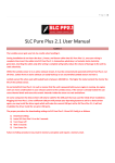
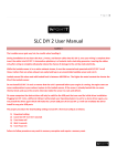
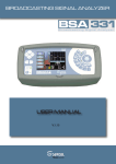
UAFC User Manual
UAFC User Manual, Release Date: Nov 15 2012
1
Important:
UAFC is compatible with 0-5[v] MAP/MAF sensors which output an analog voltage proportional to Manifold pressure or intake airflow.
Frequency based sensors such as Karman Vortex airflow sensors are not supported.
During installation do not insert the screw terminal block into UAFC, once your wiring is complete then insert the screw terminal block into
UAFC. Automotive upholstery is a fantastic static electricity generator, inserting the screw terminal block to UAFC only after wiring is
complete will greatly reduce the chance of damage to the unit by static electricity.
On some computers the device driver will only be valid for the USB port that was used for initial driver installation. Plugging UAFC into a
different USB port will prompt your Operating System to ask for a device driver again, you may install the driver again which will make the
current USB port valid for UAFC, it will not invalidate the driver install for any prior USB ports.
Do not attach USB connection between UAFC and your PC while your vehicle is in motion. Attach USB before your vehicle is in motion.
Settings in the Fuel Globals screen are applied to all 3 memory banks. After downloading new Global settings to UAFC you must cycle power
to UAFC for the settings to take place.
The maximum voltage of the MAP/MAF output is 5[v], if for instance the MAP/MAF input voltage is 4[v] and the fuel correction scaling is
200%, the MAP/MAF voltage will not be 8[v], it will be 5[v].
1. UAFC installation
1.1 UAFC Package Contents
1x UAFC unit with pluggable screw terminal attached
1x USB cable
1x Fuse holder
2x 250ma fuse
1.2 Fuses
A fuse holder and 2x 250ma fuses are provided. You only need a single 250ma fuse, the extra is for replacement if required.
The fuse holder come with a single continuous wire connecting both ends of the fuse holder, cut the wire at the midpoint.
cut
The fuse holders open easily by twisting and pulling, observe that locking mechanism on the fuse holder is open before attempting to pull.
Insert a 250mA fuse into the fuse holder.
“System Power” Connects to switched 12[v] through the 250ma fuse + fuse holder, see section 1.3.
UAFC User Manual, Release Date: Nov 15 2012
2
1.3 Wiring
Connection Table:
UAFC Pin #
1
2
3
4
5
6
7
8
Name
System Power
System Ground
MAP/MAF In
RPM In
MAP/MAF Out
Analog Input 1
Analog Input 2
External Trigger
Connects to
Switched 12v through 250ma Fuse
Ground
Output from MAP/MAF sensor
Tachometer, low side of ignition coil
ECU
0-5[v] sensor
0-5[v] sensor
Note
Use Fuse
See next section for details
See next section for details
>5v = Fuel Bank 2 selected, <5v = normal operation
During installation do not insert the screw terminal block into UAFC, once your wiring is complete then insert the screw terminal block into
UAFC. Automotive upholstery is a fantastic static electricity generator, inserting the screw terminal block to UAFC only after wiring is
complete will greatly reduce the chance of damage to the unit by static electricity.
UAFC User Manual, Release Date: Nov 15 2012
3
Factory Setup:
Cut
MAP/MAF Sensor
Output
ECU
MAP/MAF Input
*Wire is shown in different colors for illustration purposes only.
UAFC Setup:
MAP/MAF Sensor
Output
ECU
MAP/MAF Input
UAFC
Pin 3
Pin 5
1.4 Testing your installation
UAFC ships with all Fuel Correction Tables entries set at “100”, MAP/MAF Output voltage = MAP/MAF Input voltage, this will make UAFC
transparent and allow you vehicle to perform exactly as if UAFC was not installed. Ensure your vehicle is performing the same as prior to
UAFC installation before proceeding. If your vehicle is not performing the same as prior to UAFC installation, UAFC is either incompatible
with your MAP/MAF sensor or UAFC was incorrectly installed.
UAFC User Manual, Release Date: Nov 15 2012
4
2. Software Installation:
The software can be found on the included installation CD. The filename is “UAFC_x_xx.exe”. The software is compatible with windows
XP/Vista/7 only. For the most upto date software and documentation please visit http://www.14point7.com/Support.php. Double click
“UAFC_x_xx.exe” to start the installation process.
2.1 USB Driver Installation
USB Driver Installation:
Power on UAFC, connect UAFC to your PC’s USB port using the supplied USB cable. Windows will notify you that it has detected a new device
and ask you for the location of the driver. If you used the default installation directory for software installation; the driver is located in
“C:\Program Files\UAFC\Driver”. The driver is also located in the “\UAFC\Driver” directory of the installation CD.
ComPort#:
Once the driver is correctly installed and UAFC is connected to the USB port of your PC, Your Operating System will assign a Communications
Port Number (ComPort#) to the device. You will need to know the ComPort# the Operating System has assigned to UAFC when using the UAFC
Edit software. In Windows XP you can check in “Device Manager” to find the correct ComPort#.
In the above example, the correct ComPort# is “COM3”.
On some computers the device driver will only be valid for the USB port that was used for initial driver installation. Plugging UAFC into a
different USB port will prompt your Operating System to ask for a device driver again, you may install the driver again which will make the
current USB port valid for UAFC, it will not invalidate the driver install for any prior USB ports.
UAFC User Manual, Release Date: Nov 15 2012
5
3. UAFC Hardware Usage
Memory Bank Selection:
Quickly pressing the faceplate button will select one of the 3 memory banks, each memory bank contains a 256 point Fuel Correction Table.
When memory bank 0 is selected; LED0 will be light. When memory bank 1 is selected; LED1 will be light. When memory bank 2 is selected;
LED2 will be light. You can change memory bank selections while your vehicle is in motion.
Datalogging to Internal Memory:
Holding the faceplate button for 2 or more seconds will trigger datalogging to internal memory, while UAFC is datalogging to internal memory
LED3 will be light. There is enough memory onboard UAFC to log roughly 27 minutes of data @ 10 samples per second, once the memory is full;
datalogging to internal memory will stop and LED3 will turn off. While UAFC is datalogging to internal memory; hold the button again for 2 or
more seconds and datalogging to internal memory will stop and LED 3 will turn off.
Each time datalogging to internal memory is triggered, the current datalogging session will overwrite the previous one.
External Trigger:
Pin 8 is the External Trigger pin, see section 1.2, when the External Trigger pin is greater than 5[v] UAFC will select memory bank 2, when
voltage is less than 5[v] UAFC will resume normal operations. The maximum voltage that can be applied to the External Trigger pin is 20[v].
This feature is intended to support nitrous applications, the External Trigger pin is connected to a 12[v] solenoid switch, when the solenoid is
powered UAFC will select memory bank 2, once the solenoid is switched off UAFC will restore the previous bank selection. For nitrous
applications, memory bank 0 and 1 are meant for normal vehicle operations and memory bank 2 should be reserved only for when the nitrous
is active.
UAFC User Manual, Release Date: Nov 15 2012
6
4. UAFC Edit
4.1 Establishing Communications
Select the correct ComPort, see section 2.1, and hit the “Get Device info”, UAFC Edit will query UAFC and fetch hardware and firmware IDs. It is
a good idea to hit the “Get device info” to test the communications link before attempting to download settings to UAFC.
4.2 Download, Read, Validate
Globals and Bank forms have; Download, Read, and Validate, menu items.
Download: This will download the current settings on screen to UAFC. After download, UAFC Edit will automatically validate the data by
reading the data back from UAFC and comparing it with what is on the screen.
Read: This will read the settings stored on UAFC to the screen, this will overwrite current values displayed on screen.
Validate: This will compare the settings stored on UAFC with the contents on screen. This will not overwrite any values currently displayed on
screen.
UAFC User Manual, Release Date: Nov 15 2012
7
4.3 Com Status
A Com Status screen will appear during; Download, Read, Validate, and EEPROM download, operations. This screen is for information only, you
can close the Com Status screen at any time you please.
UAFC User Manual, Release Date: Nov 15 2012
8
4.4 Fuel -> Globals
Settings in the Fuel Globals screen are applied to all 3 memory banks. After downloading new Global settings to UAFC you must cycle power
to UAFC for the settings to take place.
MAP/MAF Voltage Axis (X Axis):
This holds your X axis entries, the valid range is any decimal 0-5 inclusive. The First and the last entries are non-editable.
RPM Axis (Y Axis):
This holds your Y Axis entries, the valid range is any integer 0-15300 inclusive. The First and the last entries are non-editable. Entries should be a
multiple of 60. If your entry is not a multiple of 60, during download to UAFC the data will be rounded to the nearest multiple of 60.
RPM Pickup Config:
This allows you to configure UAFC for your specific ignition type. The “Average 2 samples” is meant for cylinders which fire at 2 different angles.
UAFC User Manual, Release Date: Nov 15 2012
9
4.5 Fuel->Bank
This screen allows you to edit the your 256 point Fuel Correction Table, yellow area. The blue area is the MAP/MAF Axis (X Axis), you can not
directly edit it in this screen, it must be edited in the Globals screen. The grey area is the RPM Axis (Y Axis), you can not directly edit it in this
screen, it must be edited in the Globals screen.
A valid entry into the fuel correction table is any integer between 0 to 255 inclusive. These values represent a % scaling of the MAP/MAF
voltage. A “25” would mean that the ECU will see 25% of the actual MAP/MAF voltage, or a 75% reduction of the Actual MAP/MAF signal. “100”
would mean no scaling. “150” would mean that the ECU will see 150% of the MAP/MAF voltage, or 1.5 times the MAP/MAF voltage.
The maximum voltage of the MAP/MAF output is 5[v]. If for instance the MAP/MAF input voltage is 4[v] and the fuel correction scaling is
200%, the MAP/MAF voltage will not be 8[v], it will be 5[v].
Right clicking with your mouse over the yellow area will bring up the; copy, set, and paste menu, for easy data editing.
Before you download a new Fuel Correction Table to the unit make sure the Memory Bank Selection is correct, Bottom middle of the screen.
UAFC has room for 3 sets of Fuel Correction Tables; Bank0, Bank1, Bank2.
You do not have to cycle power to UAFC for newly downloaded Fuel Correction Tables to take effect, they take effect immediately.
Keyboard Shortcuts:
•
•
•
•
ctrl+q = increase value by 1
ctrl+a = decrease value by 1
ctrl+d = download
ctrl+s = start/stop datalogging
UAFC User Manual, Release Date: Nov 15 2012
10
4.6 Real Time Display and Datalogging
MAP/MAF In [v]: MAP/MAF voltage from MAP/MAF sensor.
RPM: RPM.
Scale [%]: Amount of MAP/MAF voltage scaling from Fuel Correction Table.
Bank: Which memory bank is currently selected; 0,1,2.
MAP/MAF Out [V]: Scaled MAP/MAF voltage to ECU.
Col Index LB: The lower Bound column Index of the Fuel Correction Table Cell.
Col Index UB: The upper Bound column Index of the Fuel Correction Table Cell.
Row Index LB: The lower Bound row Index of the Fuel Correction Table Cell.
Row Index UB: The upper Bound row Index of the Fuel Correction Table Cell.
Input 1 [v]: Analog input 1.
Input2 [v]: Analog input 2.
“TO”, bottom middle, shows the number of communication timeouts.
“Rows Cap”, bottom right, shows the number of data rows captured to memory which can be saved to disk.
Capture Data:
This will capture the data displayed on screen to memory, only data that has been “captured” can be saved to disk.
Save Data:
This will save the data captured in memory to disk in “CSV” format. This data can be easily imported into Microsoft Excel, the data field
separator is a comma “,”.
If the Fuel Bank form is open while datalogging is active the current RPM row heading and current MAP voltage column heading will be
highlighted in pink.
UAFC User Manual, Release Date: Nov 15 2012
11
4.7 Downloading Datalogs from UAFC Internal Memory
UAFC has enough non-volatile EEPROM memory for saving up to 27 minutes of datalogging. By accessing the “EEPROM” menu item you can
down datalogs stored in UAFC EEPROM to disk in “CSV” format. This data can be easily imported into Microsoft Excel, the data field separator is
a comma “,”.
6. Warranty
14Point7 warrants this product to be free from defects for 1 year.
7. Disclaimer
14Point7 is liable for damages only up to the purchase price of it’s products. 14Point7 products should not be used on public roads.
UAFC User Manual, Release Date: Nov 15 2012
12