1
YOUR ONE-STOP SOURCE OF ELECTRONICS INFORMATION
ICD 08559
JANUARY 1987 $1.95
CANADA $2.50
i
THE MAGAZINE FOR ELECTRONICS & COMPUTER ENTHUSIASTS
-
SURFACE-MOUNT TECHNOLOGY
The "New" Microminiature Way Of Building Circuits
CLAP HANDS & TURN ON /OFF APPLIANCES
Also:
Designing Ultra -Long Delay Timers
A 4.5 -MHz FM Receiving System
Making Low -Cost Speaker Systems
Laptop Computer Enhancements
A $20 Drum Synthesizer
SMT -the new circuit and device technology (p. 18)
01
o
74820 085
Eric Grevstad's
Plus: A review of Paradise's new AutoSwtich EGA system
Don Lancaster's
impressions of: Open Access II, the Big Kiss and No-Risk Trials
finder
Electronic &
The new Word Finder giant synonym
"Hardware Hacker"
Computer News ... and more.
The .Ultimate blow-Cost Test Equipment
At last! Here is your opportunity to take your pick from a new test equipment line that has all
the fea-ures you need and more
and at a price that is unbelievably low.
Here are six digital and two analog instruments
see them at your local
distributor to make your choice.
.
MODEL 9670
Digital capacitance
tester covering
0.1 pF to
20.000 µF
MODEL 9340
$9900
Pocket size, 31/2 -digit
DMM with 20 megohm
range and 10 megozrn
input resistance
$4400
MODEL 9301
31/2- digit, hand -held
DMM with 0.25%
basic accuracy and
2,000 -hour battery life
MODEL 9370
31/2 -digit autorangin9_
DMM with a memory
mode and A:3¢o basic
DC
accuracy
só9oo
5900
MODEL 9120
'+A.
m
Analog VOM with
12 A DC range
and output jack
$3900
w_
.._
4.47'
MODEL 3401
4112- digit. full function
hand -held DMM with
.05% accuracy and
data hold
12900
MOCEL 9701
digi-clampTM compact
AC clamp -on volt-ohmammeter with data hold
§69°'
mercer
ELECTRONICS
Division of Simpson Electric Company
859 Dundee Avenue, Elgin, IL 60120 -3090
(312) 697 -2265 Telex 72-2416
CIRCI.E 32
CSN
FREE INFORMATION CARD
MODEL 9101
Compact VOM
with 27 ranges,
including a 100
megohm range
$2900
Mercer Electroiics products reflect the design and quality standards
established by Simpson Electric Company, an industry leader for over 50
years and known worldwide for its integrity and product excellence.
In Stock...Available Now! Stop in at your nearest distributor and see
this new, complete line of Mercer test instruments. For the name of the
MERCER distributor in your area, call (312) 697 -2265, or send for our
new line catalog.
Which Way To YOUR Future?
Are you at a crossroads in your career?
Have you really thought about it? Are
you planning for your future, or perhaps
refusing to face the subject? Which way
down the same old road?
will you go
Or are you ready for something else?
-
In electronics you can't stand still. If you
are not moving ahead, then you're falling
behind. At the crossroads of your career,
and, yes,
various choices are available
decisions have to be made.
-
Which road will you take
one that
doesn't go where you want to be, or one
that leads to hard work but also to the
better life? Ah, decisions, decisions!
Put Professional
KNOWLEDGE
and a
COLLEGE DEGREE
in your
Electronics Career
through
HOME STUDY
Career decisions are so important that you need all the input
you can get before locking-in on one of them. Grantham College of Engineering offers you one source of input which may
help you in making that decision. It's our free catalog.
Ask for our free catalog and you may be surprised to learn how
it is easily possible to earn a B.S. degree in electronics without
attending traditional classes. Since you are already in electronics
(you are, aren't you?), you can complete your B.S. degree work
with Grantham while studying at home or at any convenient
place.
But don't expect to earn that degree without hard
work. Any degree that's worth your effort can't be
had without giving effort to the task. And of course
it is what you learn in the process, as much as the
degree itself, that makes you stand out above the
crowd
that places you in an enviable position,
prestige-wise and financially.
-
Grantham College of Engineering
10570 Humbolt Street
Los Alamitos, California, 90720
',.,-....-.
..,_._....v.-.,.,.,
Ths booklet
R E !!.\Gro
F
This free booklet
explains the
Grantham B.S.
Degree Program,
offered by independent study to
those who work
in electronics.
for
wing
iNOEEES.°UpV
°o....,p
1PONCS
ENGN`
vl
tKMNaa+
19s
gUlLE11N
Say You Saw It In Mode -n Electronics
Grantham offers this program, complete but without laboratory, to electronics technicians whose
objectives are to upgrade their level of technical
employment.
Recognition and Quality Assurance
Grantham College of Engineering is accredited by
the Accrediting Commission of the National Home
Study Council, as a degree-granting institution.
All lessons and other study materials, as well as corn munications between the college and students, are in the
English language. However, we have students in many
foreign countries; about 80% of our students live in the
United States of America.
r
FREE
10570 Humbolt Street,
Booklet
Los
11-14.s7
Alamitos, CA 90720
Please mail
CLIP
COUPON
and mail in
envelope or
paste on
postal
card.
Grantham College of Engineering
B.S.
me your free catalog which explains your
Degree independent -study program.
Age_
Name
Address
L
State
City
January 1987
/
Zip
MODERN ELECTRONICS /
I
EDITORIAL STAFF
11111111EVAN4Ks
THE MAGAZINE FOR ELECTRONICS
.3
COMPUTER ENTHUSIASTS
Art Salsberg
Editor -in -Chief
Alexander W. Burawa
Managing Editor
Dorothy Kehrwieder
VOLUME 4, NUMBER 1
JANUARY 1987
FEATURES
18
Surface -Mount Technology
A technological wave that will change the way we
build circuits. By Forrest M. Mims III
28
SMT on the Move
By Patrick J. Chick
30
How to Design Ultra -Long -Delay Timers
Get timing delays from a few microseconds to almost
30 days. By John T. Bailey
18
40
Hand -Clap Electronic Control
Clap your hands to turn on and off electrical
appliances. By James H. Brown
44
A $20 Drum Synthesizer
Project produces percussion sounds for amateur
musicians and experimenters. By C.R. Fischer
50
)
f-
Laptop Computer Enhancements
Ideas to relieve the special woes of using a laptop
computer. By Brent Gloege
117V ac, 10A
DPDT RELAY
54
A 4.5-MHz FM Receiving System
Picks up sound from TV sets and other 4.5 -MHz
sources and delivers an amplified output suitable for
driving an audio amplifier. By Duane M. Perkins
40
64
A Full -Range Speaker System
A nice -sounding, low -cost speaker system you build
in just a few hours. By William R. Hoffman
68
A Bulk Eraser for Cassettes & Diskettes
By Adolph A. Mangieri
PRODUCT EVALUATIONS
16
Paradise AutoSwitch EGA
By Joseph Desposito
54
COLUMNS
72
Hardware Hacker
Author answers readers' questions. By Don Lancaster
76
Software Focus
Word Finder -A Giant Synonym Finder.
By Art Salsberg
80
PC Papers
First impressions: Open Access II; a Big Kiss;
No -Risk Trials. By Eric Grevstad
DEPARTMENTS
4
Editorial
By Art Salsberg
Modern Electronics News
12 New Products
78 Books & Literature
79 Letters
91 Advertisers Index
6
30
2
/
MODERN ELECTRONICS
/
January 1987
Production Manager
Elizabeth Ryan
Art Director
Barbara Scully
Artist
Pat Le Blanc
Florence Martin
Phototypographers
Hal Keith
Illustrator
Bruce Morgan
Photographer
Joseph Desposito, Leonard Feldman,
Eric Grevstad, Glenn Hauser,
Don Lancaster, Forrest Mims HI,
Stan Prentiss
Contributing Editors
BUSINESS STAFF
Richard A. Ross
Publisher
Art Salsberg
Associate Publisher
Dorothy Kehrwieder
General Manager
Frank V. Fuzia
Controller
Arlene Caggiano
Accounting
Cheryl Chomicki
Subscriber Services
SALES OFFICES
Modern Electronics
76 North Broadway
Hicksville, NY 11801
(516) 681-2922
Eastern Advertising Representative
Herb Pressman
76 North Broadway
Hicksville, NY 11801
(516) 681-2922
Midwest & West Advertising Representative
Market /Media Associates
1150 Wilmette Ave.
Wilmette, IL 60091
(312) 251-2541
Ted Rickard
Kevin Sullivan
Offices: 76 North Broadway, Hicksville, NY 11801. Telephone: (516) 681 -2922. Modern Electronics (ISSN 07489889) is published monthly by Modern Electronics, Inc.
Application to mail at second class rates pending at
Hicksville, NY and other points. Subscription prices
(payable in US Dollars only): Domestic-one year
$16.97, two years $31.00, three years $45.00; Canada/
Mexico -one year $19.00, two years $35.00, three years
$51.00; Foreign -one year $21.00, two years $39.00,
three years $57.00. Foreign Air Mail-one year $74.00,
two years $145.00, three years $216.00.
Entire contents copyright 1987 by Modern Electronics,
Inc. Modern Electronics or Modern Electronics, Inc. assumes no responsibility for unsolicited manuscripts. Allow six weeks for delivery of first issue and for change of
address. Printed in the United States of America.
Postmaster: Please send change of address notice to
Modern Electronics, Inc., 76 North Broadway, Hicksville, NY 11801.
Say You Saw It In Modern Electronics
CABLE -TV
LOWEST
PRICES
ANYWHERE
1
WE'LL
N
T
F
S
HOL
ADVERTISED
BONANZA!
S
C
E
NYONE'RICES!
OR
MATCH OR WHOLESALE
SINGLE
UNIT
PRICE
ITEM
RCA 36 CHANNEL CONVERTER (CH. 3 OUTPUT ONLY)
PIONEER WIRELESS CONVERTER (OUR BEST BUY)
LCC -58 WIRELESS CONVERTER
E
DEALER
10 -UNIT
PRICE
29.95
18.00 ea.
88.95
72.00 ea.
76.00 ea.
92.95
105.95
90.00 ea.
JERROLD 450 WIRELESS CONVERTER (CH. 3 OUTPUT ONLY)
109.95
58.00 ea.
SB ADD -ON UNIT
Call for specifics
UNITS FOR SCIENTIFIC ATLANTA
BRAND NEW
109.95
58.00 ea.
MINICODE (N -12)
119.95
62.00 ea.
MINICODE (N -12) VARISYNC
179.95
115.00 ea.
MINICODE VARISYNC W /AUTO ON -OFF
70.00 ea.
139.95
M -35 B (CH. 3 OUTPUT ONLY)
125.00 ea.
199.95
M -35 B W /AUTO ON -OFF (CALL FOR AVAILABILITY)
109.95
58.00 ea.
MLD- 1200 -3 (CALL IF CH. 2 OUTPUT)
14.00 ea.
24.95
CH. 3
INTERFERENCE FILTERS
18.00 ea.
29.95
JERROLD 400 OR 450 REMOTE CONTROLLER
185.00 ea.
225.00
ZENITH SSAVI CABLE READY (DEALER PRICE BASED ON 5 UNITS)
Please Call
Other products available
SPECIFY CHANNEL 2 or 3 OUTPUT
-
-
-
A
T
Quantity
Pnc,
Output
Channel
Item
Ea(
TOTAL
PRICE
N
T
A
COD 8 Credit
Add 5%
Cards
TOTAL
Prices subject to change without notice.
Address
-_
A
T
L
A
Acct
I
:
Money Order
N
-City
Phone Number
Zip
I
:
COD
I
C Visa
F.
Mastercard
Exp. Date
#
Signature
FOR OUR RECORDS:
-
I, the undersigned, do hereby declare under
DECLARATION OF AUTHORIZED USE
penalty of perjury that all products purchased, now and in the future, will only be used on cable
TV systems with proper authorization from local officials or cable company officials in
accordance with all applicable federal and state laws.
Dated:-
Signed
Pacific Cable Company, Inc.
RESEDA, CA 91335
-No Collect Calls
(818) 716 -5140
73251/2 RESEDA BLVD., DEPT.
(818) 716 -5914
4111110(
C
U
Name
L Cashier's Check
S
F
T
A
SUBTOTAL
Shipping Add
$3.00 per unit
California Penal Code #593 -D forbids us
from shipping any cable descrambling unit
to anyone residing in the state of California.
State
U
N
T
N
L
A
N
#_211_
IMPORTANT: WHEN CALLING FOR INFORMATION
Please have the make and model # of the equipment used in your area. Thank You
T
S
LOWEST
PRICES
ANYWHERE
X1111
EDITORIAL III
When It Goes Bad
Repairing and maintaining electronic
equipment and computers ranks high
among the interests of Modern Electronics readers. We know this because 76.1%
said so when we made an intensive readership study last year. This figure was
corroborated by other responses. For example, 65.4% of respondents noted that
they were professionally involved in electronics or a related industry, while 10.4%
reported that they plan to make electronics a career. So the total here of serious
readers -those who read Modern Electronics for both professional and avocational reasons -virtually matches the
number who expressed a strong interest
in electronic servicing.
From the foregoing, I assume that if
TV receiver,
one's own equipment
personal computer, videocassette recorder-breaks down, this group will attack
repairing of it themselves. If your experiences in this area are similar to mine, and
why shouldn't they be, many of your personal- equipment problems fall into a
"tough -dog" category that defies and
stymies all your efforts.
This might be an intermittent problem
that only occurs once a week or so at a
very late hour. The next day, when
you're bushy-tailed and ready to rip the
equipment apart, it works just fine . . .
for hours at a time. Or it might be a
breakdown that defies the standard
troubleshooting procedures that should
illuminate the problem with dispatch.
I'll share one of my recent repair challenges with you to show you what I mean.
My desktop computer, which goes through
a self-check before the user can reach a
screen prompt, startled me with a beep
sound and a screen display that indicated
there's an error, along with a numeric
code number.
Well, servicing microcomputers is akin
to servicing a home entertainment system. Actually, it should be easier I feel,
though I have much more experience
with the latter repairs. Like an audio/
video system, a personal computer can be
broken down into sections for repair purposes. Pinpointing the section, you then
start isolating the problem until you discover a defective part that's causing the
problem. Therefore, if you have a computer memory problem, you'll examine
-a
4
/
MODERN ELECTRONICS
/
RAM boards and devices, not your printer, disk drive, I/O section, or whatever.
In this instance, I was working with an
IBM PC that was converted to a hard disk machine. Therefore, I pulled out my
IBM hardware diagnostic disk and manual and looked up the code number that
appeared on the screen. The "201" indicated a memory problem, but "1055"
that preceded it wasn't listed! After some
research, however, I did find the error
code listed in an IBM operating manual.
It meant that my internal switch settings
were incorrect. But since the machine
was operating fine for about a half-year
since I made my last switch-setting
changes (upping memory to 640K), this
was impossible.
My next step was to run through the diagnostic disk's routines. It indicated on
screen that the problem was in memory,
threw up the same code number that
wasn't listed in the accompanying service
manual, and further displayed a new alphanumeric code (10BE) that pinpointed
the memory location of the defective
module. Fantastic? I thought so until I
discovered that this code, too, was not
listed in the IBM Hardware manual. Nor
anywhere else!
Calling IBM itself resulted in them directing me to the dealer from whom I
purchased the machine. Unfortunately,
the dealer isn't around anymore. So it
was suggested that I contact any other
IBM dealer and tell 'em my story. Contacting some IBM dealers, however,
didn't reveal what the codes meant
either. But I did manage to get the dealer
IBM technical assistance hotline phone
number, which I quickly called. They
didn't know what the codes meant, either,
and redirected me to their dealers.
Tired of this round robin, I proceeded
on my own, learning from the diagnostic
disk that the computer's motherboard
(64K) was fine. That left 576K of memory
in add -on boards to check out.
I changed the board switch settings to
set the machine for various memory
banks, hoping that I'd see some change
from one to another. The 128K switch setting brought up a new error code, Parity
Check 2. Buying a single 64K -bit chip
from a local Radio Shack store, I substituted it for the present chips in the parity
January 1987
locations. No changes. Then I checked
out connections again, especially the wire
strappings for IDCs (insulation- displacement connector). These are the pin openings with a slit that cuts into the wire's insulation. Connection points on an ohmmeter checked out fine again.
I knew that the problem was on this
single board, so I wrote a little note in
preparation for shipping it back to its
maker for repair. Before wrapping it up
in a package, I decided to check the connector points one last time. The very first
check I made, the 128K connection
points, did not show any continuity. I
couldn't believe it! Pulling out the wires
with long -nose pliers, and using an Xacto
knife to scrape out residual insulation, I
checked the one -inch-long piece. Again it
did not have continuity. Replacing it
with a new length in the IDCs (each end
shoved into the appropriate hollow pin
hole), double- checking it for continuity,
which was there, I replaced the board
in its computer slot, started it up, and
bingo! -there was my display prompt.
Fixed and ready to go.
Looking back, it was a simple intermittent wire break that didn't reveal itself by
looking at the insulation or by resistance
measurements. If there are any blessings,
it was in the sockets that the RAM
mounted in, which obviated any soldering work, and in a screen display that
gives some indication of where the problem lies. If there are any curses, it's for a
manual that does not cover all the error
codes that its accompanying diagnostic
disk spews out and the difficulty in getting service information from a manufacturer or dealer. Additionally, it was
interesting to observe that the IBM manual requires fighting through the written
matter to overcome unclear presentations. A similar manual by Zenith is a joy
to behold, probably thanks to a Heath
hand in it.
I'd be interested to know about your
electronic servicing experiences, which
can be shared with other Modern Electronics readers. Thanks.
Say You Saw It In Modern Electronics
THE CBS COMPACT DISC CLUB HAS THE MUSIC YOU WANT
246868. Jim
Croce-Photographs
And Memories -His
Greatest Hits. Time In A
Bottle; etc. (Soja)
349530. The
Monkees Then And
Now...The Best Of The
Monkees. Includes the
new hit Thot Was Then,
This Is
Now; etc. (Arista)
344705. Patti
LaBelle-Winner In
smash -On My
Own (duet with Michael
McDonald); etc (MCA)
You.
*Al
334391. Whitney
Houston Whitney
Houston. Greatest Love
Of All;; etc. (Arista)
347492. Glenn Miller
Orchestra -In The
Digital Mood. In The
Mood; Tuxedo Junction;
more (Digito! -GRP(
343582. Van Holen5150. (Warner Bros.)
336222. Dire Straits
Brothers In Arms.
(Warner Bros.)
345553. Branford
-
Marsolis-Romance
for Saxophone. (Digital
-CBS Masterworks)
348706. Wynton
Marsalis
Moods.
(Digital-Columbia)
346270. Wham!
333286. Phil
Collins-No Jacket
314443. Neil
Diamond's 12 Greatest
Required. Album of the
Hits, Vol. 2. (Columbia)
Year! (Atlantic)
326629. Bruce
Springsteen-Born In
Orchestra. (DigitalCBS Masterworks)
219477 Simon &
Music From The Edge
Of Heaven. (Columbia)
the U.S.A. (Columbia)
328302. Tina
Turner- Private
Hits. (Columbia)
345777 Peter
Gabriel -So. (Geffen)
346809. Dvorak:
Symphony Na 9 New
World /Carnival
Overture. The London
Dancer. (Capitol)
344812. Billy
Streisand -The
Broadway Album.
Philharmonic Orchestra.
(Verese Sarabande)
J
343327 Wynton
Ocean -Love Zone.
Morsalis -Jolivet/
44
Tomasi: Trumpet
Includes Love Zone;
more. (Jive /Arista)
Concertos.
Philharmonia
Orchestra. (Digital
CBS Masterworks)
-
336396 -396390. Billy
Joel's Greatest Hits,
Volumes 1 & 2. (Counts
as
Columbia)
2-
339226. Gershwin:
Rhapsody In Blue;
album & hits.
308049. Creedence
Clearwater Revival
Featuring John
Fogerty /Chronicle.
Greatest hits. (Fantasy)
340323. SadePromise.
#1
Smash.
(Portrait)
318089. Michael
Second Rhapsody; etc.
Jackson Thriller. Billy
(Digital -CBS Masterwork.) Jean; etc. (Epic)
342097 Barbra
(Columbia)
Double Vision.
(Warner Bros.)
-
321570. Beethoven:
Symphony Na 5,
Op. 67/Schubert:
Symphony Na 8
(Unfinished). Vienna
Phil. Orch./Lorin Maazel,
Cond. !Digital -CBS
Mathis -Most
Requested Songs.
(Digitally remasteredColumbia)
349324. Rodgers &
Hammerstein -South
Masterworks)
263293. Bolling: Suite
For Flute & Jazz
Piano Rampal, Bolling
(CBS Masterworks)
Pacific. London
Symphony Orchestra.
(Digital -CBS)
288670. Barry
Manilow- Greatest
-
348649. The
Hits. It's a Miracle;
Mandy; etc. (Arista)
343095. Philip Glass
-Songs From liquid
Days. (CBS)
Piano Concertos Nos.
3 & 4. Concertgebouw
346767 Johnny
Somewhere; Something's
Coming; more.
345827 Bob James
and Dodd Sanborn
342667 Beethoven:
Pachelbel Canon And
Other Digital Delights.
The Toronto Chamber
339200. Stevie
Wonder-In Square
Circle. #1 album.
(Tomb)
Orchestra. (Fanfare)
HUEY LEWIS
THE NEWS
i
347153
The age of CD sound is here -and you
have a practical new way to find the CDs
you want. As your introduction to the CBS
Compact Disc Club, you con choose any
2 CDs listed in this ad for just $1.00. Fill in and
mail the application-we'll send your CDs
and bill you for $1. You simply agree to buy
2 more CDs (at regular Club prices) in the
next year-and you may then cancel your
membership anytime after doing so.
How the Club works. About every four
weeks (13 times a year) you'll receive the
Clubs music magazine, which describes the
Selection of the Month for your musical
interest...plus many exciting alternates. In
addition, up to six times a year, you may receive offers of Special Selections, usually at
a discount off regular Club prices, for a total
of up to 19 buying opportunities.
If you wish to receive the Selection of the
Month, you need do nothing
will be
shipped automatically. If you prefer an alternate selection, or none at all, fill in the
response card always provided and mail it
by the date specified. You will always have
at least 10 days in which to make your
-it
i
347955
Smile. (Warner Bros.)
Garfunkel's Greatest
316604. Tchaikovsky:
1812 Overture; Marche
Slave; Beethoven:
Wellington's Victory.
Lorin Moazel, Vienna
Phil. (Digital -CBS
Masterworks)
343251. Bach:
Goldberg Variations
Glenn Gould (Digital
CBS Masterworks)
--
287003 Eagles -Their
1971 -1975.
Greatest Hits
(Asylum)
328740. Mozart
Piano Concerto
Na 26 (Coronation);
Rondos- Murray
Perahia and English
Chamber Orchestra.
(Digital-CBS
MO
347245
347054. David Lee
Roth -Eat 'Em and
Masterworks)
i
346643
i
decision. If you ever receive any Selection
without having 10 days to decide, you may
return it at our expense.
The CDs you order during your membership will be billed at regular Club prices,
which currently are $14.98 to $15.98 -plus
shipping and handling. (Multiple -unit sets
may be somewhat higher.) After completing
your enrollment agreement you may cancel
membership at any time; if you decide to
continue as a member, you'll be eligible for
our money- saving bonus plan. It lets you buy
one CD at half price for each CD you buy at
regular Club prices.
10 -Day Free Trial: We'll send details of the
Clubs operation with your introductory
shipment. If you are not satisfied for any
reason whatsoever, just return everything
within 10 days and you will have no further
obligation. So why not choose 2 CDs for
$1 right now.
ADVANCE BONUS OFFER: As a special
offer to new members, take one additional
Compact Disc right now and pay only $6.95.
It's a chance to get a third selection at a
super low price!
Selectionswith two numbers contain 2 CDs and count as 2 -so write in both numbers.
CBS C( )11 IA(',T DISC C Ll B: livre Haute,
te, I N
i
345785
COMPACT
0
DIGITAL AUDIO
346478
1
I- CBS COMPACT DISC CLUB, 1400 N. Fruitridge
Box 1129, Terre Haute, Indiana 47811 -1129
Please accept my membership application under the terms outlined
in this advertisement. Send me the 2 Compact Discs listed here and
bill me only $1.00 for both. agree to buy two more selections at
regular Club prices in the coming year -and may cancel my
membership at any time after doing so.
P.O.
I
Send me
these 2
CDs
ADVANCE BONUS OFFER: Also send me
a third CD right now at the super low price
of lust $6.95, which will be billed to me.
My main musical interest's (check onek
(But
I
may always choose from any category)
ROCK /POP
CLASSICAL
Mr.
Mrs.
Miss
Print First Nome
Lost Nome
Inmol
Address
Apt.
City
State
Zip
Do you have a VCR? (Check one.)
Yes
Do you have a credit card? (Check one.)
this offer
is
No
Yes
141/567
No
not oroiloble in APO, FPO Alaska, Hawaii, Puerto Rico: please wnte to,
details of olternotivedfer.
47811 L
Note We reserve the right to request additional information
or reject any application.
ZYV /NZ ZYW/NPJ
111111/MODERN ELECTRONICS
NEWS//Ill/Il
CONSUMER PROTECTION PROPOSALS. A California bill that requires consumer electronics manufacturers to retain functional replacement parts
for seven years passed State Assembly and cleared a Senate committee.
This is for merchandise that has a wholesale value of more than $100,
with goods in the $50 to $100 range proposed to have only a three The full Senate must pass the bill,
year parts retention requirement.
is being considered
a
go....Legislation
it
be
to
AB 3835, in order for
New
New York City
Jersey,
Iowa,
Florida,
in California, Connecticut,
merchandise.
market
graylabel
to
retailers
and San Francisco requiring
COMPUTER -AIDED -DESIGN VIDEO. A new videotape, "CAD to Reality," is
The eight -minavailable from CalComp in VHS or Beta format for $5.
ute recording outlines CAD applications in engineering, architecture
Write CalComp Videotape, P.O. Box 3250,
and facilities management.
M/S 60, Anaheim, CA 92803.
AUDIO SPEAKER DEVELOPMENTS. Matsushita Electric, parent of Panasonic,
Technics and Quasar, has developed an ultra flat panel speaker for
It's only abut 2 1/3" deep and features twin -cabinet
wall mounting.
construction to house two woofers and a mid -low speaker separately.
ft. sq., plus the afore31/2
Overall dimensions of the system are:
Impedance is 8 ohms,
mentioned depth of not much more than 2 inches.
while power handling capacity is 350 watts (music power)....Speaker
Techron
design is becoming less of an art today and more of a science.
(Elkhart, IN), for example, recently introduced its V- Box -Res software
program to make designing and comparing low- frequency speaker systems
The program also provides
more accurate, as well as faster and easier.
information on required enclosure parameters to attain performance
From collected data, its Polar program generates a polar display
goals.
for up to 400 different frequencies and Output Sound Pressure Level (dB
SPL) can be plotted at various angles on and off axis and measured
at a single frequency or band of frequencies.
APPLE SWELLS EARNINGS. Apple Computer reports it doubled earnings and
Though sales dollars
net income in fiscal 1986 (ending September 26).
were essentially the same ($1.9- billion +), net income rose 151 percent
to $154 million.
MACHINE VISION. Use of machine vision in the electronics industry will
outpace auto makers by 1990, according to a University of Michigan
The market for automated vision overall is projected to grow
study.
from $58- million to $457- million over a five -year forecast period. Almost half of the specific machine -vision applications for electronics
Color will be especially imporwill be in inspection- related tasks.
tant....The one -millionth patent since the U.S. Commerce Department began
using an automated patent printing system in 1970 was issued to Object
Recognition Systems for a machine vision system developed by Joseph
It's called "Robotic
Wilder of PA Technology and Rajarshi Ray of AT &T.
Techniques." In
Histogram
Acquisition of Objects by Means Including
from
a jumbled heap
parts
other words, it can see and choose specified
from 20 mintask
the
while
cutting
in a bin or align thick -film ICs
utes to less than a second.
6
/
MODERN ELECTRONICS
/
January 1987
Say You Saw It In Modern Electronics
* * 2 CENTS PLAIN * *
That's about all it costs subscribers for each page
of editorial matter in MODERN ELECTRONICS . . .
every month. No charge for informative advertisers'
messages. Or for free information requested on our
bound -in postpaid Free Information Service card.
A bargain? You bet! MODERN ELECTRONICS is a
veritable one -stop source of "hard" information for enthusiasts whose interests spread across the entire
spectrum of electronics and computers for work and
play. The latest technical information and news written by a galaxy of authoritative writers- Forrest Mims
on "Experimenting," Don Lancaster on "Hardware
Hacking," Stan Prentiss on "Video," Len Feldman on
"Audio," Glenn Hauser on "Communications," and
Eric Grevstad on "Personal Computers," to name a
few authors who share their specialized experiences
with readers every month.
This neat package keeps everyone abreast of the
important developments in electronics and computers. From new devices and circuits to useful construction projects to evaluations of the latest products.
Both "how to do" and "how it works" information increases your technical competence every page of the
way. Two cents a shot. And hands -on product evaluations make you a wiser buyer, whether it's on a test instrument or a video recorder. So whether you're a service technician, an engineer, a budding one in a technical career path, or an active electronics enthusiast,
MODERN ELECTRONICS will serve you well. Sub
scribe and be sure to get every information -packed is-
sue delivered to you every month. It's important reading you can't afford to miss!
Just fill out the coupon and mail with your check,
money order or credit -card information (Visa or MasterCard) to enter your subscription. Do it today to ensure earliest delivery!
MODERN ELECTRONICS
76
North Broadway, Hicksville, NY 11801
Please send me Modern Electronics for
3
Years
2
Years
1
.
Year
Name
Street
City
Zip
State
Charge My Order To: Payment Enclosed
VISA
Years (36 issues)
2Years(24issues)
$45.00
$31.00
Year(12 issues)
$16.97
3
MasterCard
$
1
Account Number
H
-
1-
SCOPE PRICE BREAKTHROUGH!
New B&K-PRECISION
Dual-Trace 20MHz Scope...
$440::
Now you can own a professional quality 20MHz,
dual -trace scope for under $450. Best of all, it's a full
featured instrument, from B &K- PRECISION -famous
for quality, dependable products.
Compare these outstanding features, then compare price!
Dual or single trace operation 2mV /div sensitivity
20MHz response at a true -3dB AUTO /NORM triggered
sweep operation with AC, TVH, NV and Line coupling
Calibrated 18 step timebase with x10 magnifier X-Y operation Bright, sharp rectangular CRT with P31 phosphor
Front -panel trace rotation control Tilt stand and soft
handle Selectable +/- slope Built -in calibration source
Compact low- profile design.
For immediate delivery, contact your local B&K- PRECISION
distributor or call B &K- PRECISION today.
DYNASCAN
r+KPRECISION CORPORATION
6460 West Cortland Street
CIRCLE 4 ON FREE INFORMATION CARD
Say You Saw
It In Modern Electronics
Chicago, Illinois 60635
312/689-9087
CanadianSales .AtIasElectronics.Ontario
International Sales,6460WCOrtland St..Chlcago,Illin0is60635
Sou, and Central Americco Sales, Empire Exporters, Plainview, NY 11803
January 1987
/
MODERN ELECTRONICS
/
7
Only NRI gives you a 27" high- resolution
stereo color TV you build to prepare you for
today's video servicing careers.
...
Become one of America's most sought-after technicians
put your talents and spare time to work for you in the
"explosive -growth" world of home entertainment electronics.
Train in state-of-the-art video /audio
servicing and become a fully qualified
service pfofessional the uniquely successful NRI way. It's hands-on training, at home ... designed around the
latest electronic equipment you build
and keep as part of your training. You
start from scratch and "discover by
doing" You conduct key experiments
... pe rfo rm vital tests ... build your
own systems ... and do it all at the
pace that suits you best.
There's no stopping the incredible
boom in consumer electronics. Soaring
sales, new and improved video products, entirely new technologies have
opened up new opportunities for the
trained technician as never before.
Now at $26 billion in annual sales,
the consumer electronics industry is
creating a whole new servicing, installation, and repair market. This yeas TV
sales alone are expected to hit 16.2
million units. Every day, sales of home
VCRs, a product barely conceited of
10 years ago, reach 20,000 units. Every
day!
And the revolution has spread to the
business sector as tens of thousands
of companies are purchasing expensive high -tech video equipment used
for employee training, data storage,
even video conferencing.
The Video Revolution
Is Just Starting
Hands-On 'raining As You Build
a 27" Stereo TV
Already, disc players can handle audio
CDs and laser video discs. And now
In just hours you assemble an exceptional state-of-the-art TV receiver using
easy to follow, step -by-step instructions.
During this assembly process, you learn
to identify and work with components
and circuits used in actual commercial circuitry. Then through tests, adjustments, and experiments you quickly
there are machines that will accommodate laser computer disks as well.
Camcorders are becoming smaller,
lighter; and more versatile ... 8 mm
video equipment produces high resolution pictures and digital audio.
By 1990 our TVs will become interactive computer terminals, giving us
entertainment, information, and communications in one sophisticated
video /computer/audio system.
master professional troubleshooting
and bench techniques.
Join the Future or
Be Left Behind
Can you see the opportunity? The
ser
icing and repair market that's there
already ... and the enormous future
need created by the millions upon millions of electronic devices yet to
NW/ ACTION AUDIO
come? If you're looking for a highyou'd
like
potential career ... if
ME
'.
.......... .,,
,.
to get started in a field that's still
wide open for the independent
e
businessperson ... even if you'd
like to find a way to make extra money
part-time, look into NRI at-home training now
set up today your complete home
video center of the future. Flat screen,
square corners, and a black matrix to
produce dark, rich colors. Cable compatible tuning, built -in stereo
decoder to give you superb reproduction of stereo TV broadcasts ... even
a powerful remote control center that
gives you total command of video and
audio operating modes.
Your NRI Braining Has
fibo
q
e
specialists and instructors. Their longproven training skills and enthusiasm
come to you on a one -to-one basis.
Available for consultation and help
whenever you need it, your instructors ensure your success both
14e
during your course and after
graduation.
to profit from the new explosive
growth in consumer electronics.
You study at home in your spare
time at your own pace. No classroom pressures, no night school
grind.
Even if you've never had electronics training, NRI prepares you
properly with a thorough grounding in the fundamentals ... a foundation that you build on to achieve
advanced electronics skills. With
this kind of understanding and
practical bench experience built
into NRI's exclusive training methods, you're on your way to take
advantage of the new opportunities opening up every day.
Since NRI training is built around
"learn by doing," right from the start
you conduct important experiments
and tests with your professional digital multimeter. You assemble the
remarkable NRI Discovery Lab and perform a complete range of demonstrations and experiments in the process.
27" TV included with your training
has all the features that allow you to
Another Special Element
NRI training in video /audio servicing is the perfect way for you
Totally Integrated
Hands -On Training
Inside Your TV
This new state-of-the-art Heath/Zenith
Also built into your training is the enormous experience of NRI development
,-
Start Right and
There'll Be No Stopping You!
NRI has purposely designed your
training around equipment that has the
same high-tech circuitry you'll encounter in commercial equipment. That
means your training is real -world training. And that's unique.
Step Into the Future Today
The richest reward you gain
from your NRI video /audio
training is a firm grip on the
future. Your knowledge and knowhow provide you with the soundest
possible foundation for keeping up
with the rapidly evolving, highly innovative video industry.
Send For Free Catalog
Now is the time to act. Send the postpaid card to us today. You'll receive
our 100 -page catalog free. It's filled
with all the facts you'll want to know
about our training methods with full
details on the equipment you'll use
and keep as part of your hands -on training. You'll see how our more than 70
years of experience in uniquely successful at-home career training makes
us the leading technical school today.
(If someone has already used the card,
write to us at the address below.)
NRI's commitment to you goes beyond
providing you with equipment appropriate to the latest technology. Of equal
importance is our dedication to training
techniques that let you master 1V, video
and audio troubleshooting and repair
quickly and easily. Best of all, we ensure
that in the learning process you acquire
the very skills that will make you a professional service technician on the job.
AMPArSchoois
McGraw-Hill Continuing
Education Center
3939 Wisconsin Avenue, NW
Washington, DC 20016
llIiu/NEW PRODUCTS
For more information on products
described, please circle the appropriate number on the Free Information
Card bound into this issue or write to
the manufacturer.
Deluxe Car Stereo
Kenwood's Model KRC-999 car audio system offers 44 separate computerized functions controlled by an
outboard 16 -bit microprocessor
module. Access to the preamp, tuner
and tape functions programmed into
memory are via buttons on a motorized control shelf. Two preset volume levels, a manual volume control
20 -dB mute button are
and a
available.
A seven -band graphic equalizer
provides a ± 12 -dB range at 60, 120,
150, 500, lk, 3.5k and 10k Hz. Four
-
IIII
factory preset equalization curves,
three user -programmable curves and
manual operation are offered. A
peak -hold spectrum analyzer displays relative frequency levels.
The three -motor, auto -reverse
cassette deck has a rated 20-to- 22,500Hz frequency response with metal
tape. S/N is 62 dB with no noise reduction and 71 dB with Dolby B, 76
dB with Dolby C and 86 dB with dbx
NR. Wow and flutter are 0.06%
wrms. A multifunction indicator dis
plays the operating modes, and a
LED display indicates the amount of
tape remaining.
The PLL synthesized AM /FM
tuner section has 15 FM and five AM
presets. A preset scan feature allows
the user to sample the preset stations
for 5 seconds. $1,300.
CIRCLE 8 ON FREE INFORMATION CARD
KENwooD
I
Z°"..:..,r0,
ff.áll
...
;
-
A moderately priced digital oscillo-
scope /spectrum analyzer peripheral
plug -in for selected personal computers has been announced by Rapid
Systems of Seattle, WA. Models are
available for IBM, Apple and Commodore computers.
The digital scope has four diode protected input channels and features: 100 -Hz to 2 -MHz sampling
rate (14 steps); gain adjustable from
100 mV to 20 V /div. (8 steps); 500 -Hz
analog bandwidth; 2K data buffer;
and separate adjustable trigger input. Software features include:
menu- driven operation; a help file;
color graphics; keyboard control of
/
MODERN ELECTRONICS
lllriIl.
I I_I
Pi
Though it is small enough to fit into a
shirt pocket, OPTOelectronics' (Ft.
Lauderdale, FL) Model 1300H frequency counter is not short on bandwidth. The 4 "H x 3.5 "W x 1 "D
counter has a specified bandwidth of
-
(
I
.
Personal Computer
Scope /Analyzer Board
12
CIRCLE9ON FREE INFORMATION CARD
1.3 -GHz Frequency Counter
...
-
time series data to spectrum analyzer
for frequency analysis.
$798 for Apple and IBM computers; $649 for Commodore computers.
trigger, gain and timebase; assembly
routines to speed data collection and
display; zoom mode to view entire
data buffer; active scrolling; grid display; store /retrieve functions; post
trigger delay; multi -channel display;
print screen; and user -definable interface routines.
The spectrum analyzer features:
FFT sizes from 16 to 1024; 2 -s (16point) to less than 10 -s (1024 -point)
execution time; 100 -Hz to 500 -kHz
sample frequency; 1.6 -to -320 -V p -p
inout range; rectangular or Nanning
windows; baseband or vernier operation; power spectrum computation
and averaging; better than -Hz resolution; disk save /recover spectrums;
hardware /software /keyboard triggering; and transfer of digital scope
/ January 1987
1
from
MHz to beyond 1.3 GHz.
Measured frequencies appear in an
eight -digit red 0.28 " -high LED display. Input to the instrument is via a
BNC connector.
Switches are provided for ac /battery operation, fast /slow gate time,
high/normal sensitivity and 1 -to1
Say You Saw It In Modern Electronics
and 500-to -1,300-MHz
range selection. Additional features
include a measurement -in- progress
indicator and calibration adjustments that can be made without having to open the case.
Rated resolution is to 1 kHz in
0.25 second or to 100 Hz in 2.5 seconds over the entire range of frequencies. Accuracy is rated at
± 0.0001% ± 1 count LSD, achieved
with an RTXO timebase. Supplied
with the counter are internally installed rechargeable nickel- cadmium
cells and an adapter for ac operation
and battery charging. Optional accessories include a carrying case,
probe and telescoping antenna. $150.
500 -MHz
CIRCLE 10 ON FREE INFORMATION CARD
Wood-Stove Monitor
A new electronic device called the
"Just Rite Monitor" from Inventex
a chimney fire or it gets cool enough
for the fire to go out. The Monitor
can also drive a digital telephone
dialer that can contact a central
alarm station to send help in the
event the alarm goes off when no one
is at home. $79.95 plus $2.95 P &H.
CIRCLE
11
RITE
MONITOR
P.
,r
550
HI
500
LOW
4
430
írb
400
4b
ALARM
+
3.i0
300
LOW
SET
RS-232 Interconnect
Problem Solver
Connect from Black Box is
designed to solve interconnect problems for users of equipment with
RS -232 serial interfaces. It offers an
easy -to -use cabling system for all
types of connectors, including those
used on IBM PC and compatible and
Apple Macintosh computers to convert the various types of serial connectors now being used into a simple
modular system. The adapters terminate with standard modular jacks
EazyrM
requirements of videocassette recorders. The wrenches are made to
match the configuration of the recesses for adjusting tape feed, tape
tension and various other functions
in VCRs. They are available for both
Beta and VHS machines.
CIRCLE
13 ON
FREE INFORMATION CARD
Digital L CR Meter
A handheld digital instrument that
measures the values of coils, chokes,
transformers, capacitors and resis-
and are connected by telephone-type
RJ -12 cable. This enables quick connect and disconnect of equipment
and elminates the need to run large,
unsightly cables between equipment.
Eazy Connect is a family of adapters. Each is designed to attach to the
most popular computers, printers,
modems and other peripherals to
which they permanently attach. An
Eazy Connect Switch then allows
data routing between up to four
computers and one peripheral or between four peripherals and one computer to which the Adapters are connected. Additionally, the system can
be cascaded to provide a low -cost
network capability.
CIRCLE
Say You Saw It In Modern Electronics
New from Philips ECG is a set of
eight special- purchase wrenches that
are designed to meet the adjustment
ON FREE INFORMATION CARD
Inc. (Lehigh Valley, PA) gives the
flue temperature of wood stoves so
that conditions can be adjusted to
maintain an even, comfortable tern perature. Discrete light- emitting diodes display temperature over a 300 °
F to 550 ° F in 50 ° increments. Other
LEDs provide visual indication when
flue temperature rises above or falls
below safe limits. A built -in alarm
provides an audible alert when flue
temperature gets hot enough to cause
JUST
VCR Adjustment Wrenches
12 ON
1800
FREE INFORMATION CARD
January 1987
/
MODERN ELECTRONICS
/
13
NEW PRODUCTS
tors has been introduced by Elenco
Electronics. The Model LC -1800 has
an inductance range of 0.1µH to 200
H, capacitance range of 0.1 pF to 200
µF and resistance range of 0.1 ohm to
20 megohms. Basic measurement accuracy is ± 1% of reading, while
resolution is 0.1 µH, 0.1 pF and 0.1
ohm.
Convenient switches along the left
side of the meter's case access seven
each inductance and capacitance
ranges and six resistance ranges. A
separate slide switch located under
the display is used for selecting the L,
C and R functions. All measurement
values are displayed on a liquid -crystal display. A 9 -volt battery powers
the instrument for up to 200 hours.
The meter measures 6.8 "H x 3.5 "W
x 1.4 "D. $199.
CIRCLE
14 ON
FREE INFORMATION CARD
Wireless VCR Microphone
"SoundCatcher" is a remote microphone from SIMA Products Corp.
(Chicago, IL) that allows the home
video photographer to record sounds
from subjects up to 200 ft. distant. It
can be hand -held or clipped to a belt
as desired. The receiver is compatible
with any video camera. A Velcro attachment gives the user a choice of
Stand -Alone Modem
from Practical Peripherals
(Westlake Village, CA) is the Model
1200 SA fully Hayes -compatible
stand -alone modem. This 300/1200 baud modem features auto -dial/
auto -answer capabilities, supports
all communications software and includes an upgrade path for a programmable enhancement card. Automatic adaptive equalization is built
in for consistent and error -free operation over the telephone line. Other
features include semipermanent storage of up to 10 telephone numbers,
menu -driven configuration
(no
switches to be set), pulse or tone dialing, volume -controlled speaker, and
two modular jacks to accommodate
voice and data calls.
Operating modes include autoNew
where to place the receiver on the
camera.
Plugging into the camera's input,
the receiver also has an earphone
that allows the user to audit the
sound while shooting a scene. A dual
LED panel signals when the unit is
operating and sound is being received. Supplied with the Sound Catcher is a soft carrying case.
$134.95.
CIRCLE 15 ON FREE INFORMATION CARD
14
/
MODERN ELECTRONICS
/ January 1987
matic answer and originate selection,
computer -controlled dialing and
answering, autodial- from-memory
and automatic speed mode detection. Indicators come on for Modem
Ready, Receive Data, Hi -Speed 1200
Baud, Phone Off -Hook, Transmit
Data, Carrier Detect and Auto -Answer. Included with the modem are a
plug -in power supply, data interface
cable, user manual and CMB Priority Response Card. The modem measures 10.5 "D x 5.5 "W x 1.3 "H and
is designed to fit under a desk -type
telephone. $239.
CIRCLE
16 ON
FREE INFORMATION CARD
X/K-Band Radar Detector
The Micro Eye Express from B.E.L. Tronics Ltd. (Mississauga, Ont., Canada) is claimed to be the world's
most sensitive automotive radar detector. It is said to be about 20 percent more sensitive than the company's previous XPR Long Range
model detector. The new model uses
a two -stage amplifier that examines a
single sideband to reduce noise and
increase sensitivity.
Say You Saw It In Modern Electronics
Micro Eye Express is designed to
mount either on the dashboard (in an
adjustable bracket) or on a visor. It
comes with dash bracket, visor clip,
Velcro strip and cigarette-lighter
plug. $299.95.
CIRCLE
17 ON FREE
INFORMATION CARD
Famous
Optical Fiber Stripping Tool
"Opti- Strip" from Davle Tech
(Fairlawn, NJ) is a unique stripping
tool designed specifically for removing the secondary coating from optical fibers. It handles both loose- and
tight -fit fiber -optics cables of any
length. Damage to the optic core
during stripping is prevented with
supplied front and rear guide bushings that exactly locate the cable in
relation to the stripping blades and
eliminate "sagging" during stripping.
A very special computer &
electronics guide that shows
you what the exciting world of
kitbuilding can do for you.
Challenge. Knowledge. Achievement. Enjoyment. All of these things are yours when you build
a Heathkit high -quality product. Our colorful, informative catalog reflects the years of experience
and technological expertise that make these
things happen for you.
#-.-_Amateur Radio Terminal
Node Controller
Educational
Robot and Courseware
HERO`.. 2000
IBM -PC Compatible
Depth of cut is infinitely variable
between 0 and 0.118" (0 to 3 mm).
The tool is light in weight and easy to
use. It comes with its own storage
case, a set of different -size guide
bushings and full instructions.
CIRCLE 18 ON FREE INFORMATION CARD
Circuit Design Program
CompDes from Esoft Software (Columbus, OH) is a low-cost electronic
circuit design program that runs in
IBM PC and compatible computers.
Designed for students, technicians
and engineers, this menu -driven
software tool has menu selections
that start with Basic Electricity and
work up to Circuit Designs. The soft-
(Continued on page 85)
Electronic Keyless Doorlock
Expandable Computers
In our catalog you'll find over 450
from
interesting and useful items
computer hardware and software to
robots and test instruments, and from
home security systems to color tv's
and amateur radio equipment.
But what makes Heath Company
unique is that we offer you the confi-
-
Send
dence and pride that you can only get
by building a state -of- the -art product
yourself. And you're backed by our
promise, "We won't let you fail"
The Heathkit Catalog is a simple
and FREE first step toward this excellent opportunity.
-
-
S NOW for your
FREE Heathkit Catalog
1
Yes!
want to see what kitbuilding can do for me.
Please send me the latest Heathkit Catalog Free.
I
Send to: Heath Company, Dept. 079 -492
Benton Harbor, Michigan 49022
Name
Address
Heathkifm
State
I
C'ty
Heath
Company
CL -787R1
J
L
CIRCLE 79 ON FREE INFORMATION CARD
Say You Saw It In Modern Electronics
El
Zip
IA subsidiary of Zenith Electronics Corporation
January 1987
/
MODERN ELECTRONICS
/
15
IIIi//PRODUCT EVALUATIONS/li
IIN
The Paradise AutoSwitch EGA: A video card
that automatically changes displays to suit the software
A new EGA video card from Paradise
Systems, Inc. is half the size of the IBM
version, yet gives you more functionality
at a lower price. The Paradise Auto Switch EGA automatically senses the
display needs of application software and
changes to the correct operational mode
(EGA, CGA, Hercules, etc.). Additionally, the card contains 256K of video
RAM. The AutoSwitch EGA card is for
the IBM PC, XT, AT and 100% compatibles and sells for a suggested retail price
of $599.
Overview
The Paradise AutoSwitch EGA board is
about 5.5" long and 4" high, which
means it can fit into a short expansion
slot such as the one found on the IBM PC
XT. Despite its size, it packs all the features of IBM's EGA board, foremost of
which is the ability to drive a high- resolution EGA monitor and display 640 x 350
high -resolution graphics in 16 colors.
At the top center of the board is a 1.25 "
square custom VLSI chip, which makes it
possible to have a low chip count, low
power consumption, and small board
size. This chip not only is designed for
EGA compatibility, but because it contains the equivalent of a Motorola 6845
CRT controller, it is also designed for
IBM CGA and Hercules compatibility.
Along the left -hand side are eight 4 x
64K video RAMs, which provide the card
with 256K of display memory. Compare
this to IBM's card, which has just 64K of
video RAM on board and needs a piggyback board to expand to 256K.
At the rear of the board are several
switches and connectors. The main
switch is a 5- position DIP switch. Four of
them are used to set the system configuration, just as with the IBM version, and
the fifth is used to set the autoswitch feature on or off. A second switch is a toggle
switch, which lets you select the type of
monitor in use.
A monitor connects to the board via a
DB -9 connector. Two RCA jacks on the
board are not currently supported by the
hardware. On theboard itself, there are a
6 -pin connector for a light pen and a 32-
16
/
MODERN ELECTRONICS
AutoSwitch
EGA
Card
pin connector that provides all monitor
signals (six color bits, horizontal and vertical syncs, and blanking) and related
adapter signals.
The AutoSwitch can coexist with either a monochrome display adapter or a
color graphics display adapter and can be
used as either the primary or secondary
display. When used with another adapter, however, the autoswitch feature cannot be used.
The board can work with three different types of monitors: enhanced color,
RGB color, and monochrome. And the
card has downward compatibility with
the IBM color graphics adapter and
monochrome display adapter, the Hercules monochrome graphics card and
Plantronics ColorPlus card.
Installing AutoSwitch
Installing the AutoSwitch is just like installing any other expansion board for
the IBM PC series of computers. On the
PC and XT, system -board switches must
be set, and on the AT, a Setup program
must be run.
Depending on the type of monitor you
have, you must set the switches at the
back of the AutoSwitch board. If you are
using an EGA monitor, the toggle switch
is set to the right, and positions 1 through
/ January 1987
4 of the DIP switch are set on- off-off-on.
These switches can be set from the rear of
the computer without removing the cover. For a monochrome or standard RGB
monitor, the toggle switch is set to the
left, and the DIP switch is set to off -offon -off and off-off -off -on, respectively.
For an enhanced RGB monitor, the DIP
switch would be set to off-on -on -off.
Whatever monitor is used, one can select
whether or not automatic mode switching is used by setting position 5 of the
switch to on for "yes" or off for "no."
Using AutoSwitch
We tested the capabilities of the Auto Switch with Lotus 1 -2-3 Version 1A, inserting the board into an IBM- compatible AT and connecting it to a Princeton
Graphics EGA monitor. The toggle
switch on the board was set to the right
and the DIP switch was set for the EGA
mode. Normally, the 1 -2-3 spreadsheet
will work in the high -resolution mode,
but will not display graphics. (EGA
drivers are now available for V. 1A, but
we did not use them.)
When we tried to display a graph, the
AutoSwitch sensed it and immediately
changed to RGB mode rather than blanking out, which the IBM version did. One
minor adjustment had to be made in the
Say You Saw It In Modern Electronics
C
7
0MB
TN-
Authorized Liquidator
vertical hold, however. Once this was
done, we switched back and forth from
the spreadsheet to graphics without any
problems.
Our next test was done with a monochrome monitor. Since we changed monitor, we had to flip the toggle switch to
the left and reset the DIP switch for
monochrome. Normally, with IBM's
monochrome card, 1 -2-3 graphics cannot
be displayed. We used the Lotus Utility
disk to enable the monochrome drivers
for 1 -2-3. We could not display graphics,
naturally, since the AutoSwitch was
emulating the IBM monochrome card.
We then used the Utilities disk to switch
to install the Hercules drivers on the 1 -2-3
program. Now we could display graphics, since the AutoSwitch sensed the new
drivers and automatically changed to
Hercules emulation.
We further tested the AutoSwitch by
trying to run a game program called
"Digger" that would not run under the
IBM EGA. The program came up in
CGA mode and ran perfectly.
AutoSwitch Software Utilities
A utilities disk is included with the Auto Switch hardware. One program on the
disk checks the BIOS ROMs in an IBM
PC. If you have a PC manufactured in
1981 or 1982, you must upgrade the
ROMs -the older ROMs do not support
EGA. The other program lets you take
control of AutoSwitch through software.
This program overrides the default setting of the switch that controls the auto switch feature. It also allows you to boot
game disks with exotic copy-protection
schemes.
Comments & Conclusions
IBM's EGA card, which lets you display
640 x 350-pixel graphics in 16 colors, is
certainly an attractive, though expensive,
option for IBM PC, XT, AT and compatible computers. The Paradise Auto Switch EGA card that we reviewed, however, gave us a display of equal quality at
a substantially reduced price. Moreover,
it added features not found on the IBM
card that allowed us to run Lotus 1 -2-3
At A Glance
Product: AutoSwitch EGA Card
Address: Paradise Systems, Inc.
217 East Grand Avenue
So. San Francisco, CA 94080
Phone: (800) 527 -7977 (Ext. 370)
Requirements: IBM PC, XT, AT or
100% compatibles
Price: $599.
and game programs without a problem.
One could argue, however, that EGA
drivers are now available for 1 -2-3 V. 1A,
and that games aren't important on a
business computer. One might also argue
that compatibility problems may exist
between the two cards for certain applications. Although we did not experience
these problems, we did not do extensive
compatibility testing and cannot guarantee that they do not exist at all.
Since it is an EGA-compatible card,
the AutoSwitch should also be viewed in
relation to other compatible cards. Inmost cases, the AutoSwitch outperforms
these products just as it does the IBM version. In addition, its low power consumption and size, which make it ideal
for either the IBM PC or XT, could also
make it a better choice than some of the
other compatibles, though priced higher
than some of them.
To conclude, the Paradise AutoSwitch
card offers some unique features in addition to EGA compatibility, namely automatic switching. If your application has a
need for these kinds of features, then the
AutoSwitch is an excellent choice. However, if you are interested only in viewing
an EGA display, have software that supports EGA (e.g. Lotus 1 -2-3 V. 2.0), and
are shopping for price, there are some
less -expensive cards on the market. And,
of course, if your application demands
absolute IBM compatibility in every conceivable instance (which may be the case
with Paradise's AutoSwitch, but, obviously we did not check out every piece of
software extant) you may have to go with
the original board. Chances are that
you'll choose to bypass the original,
though.
-Joseph Desposito
COMMODORE®
VICMODEMTM
Use with the Commodore C64 -,
the SX -64 or the VIC -20 Computer.
Bell 103 Compatible.
Full Duplex; 300 Baud.
Manual Dial Direct Connecting.
FCC Registered.
This Modem is LOW liquidation priced
because it was closed out by Commodore' Add it to your computer for access
to timely financial information, news and
reference libraries...as near as your
phone! An affordable introduction to
phone /computer services; and you can
communicate with computer users who
also own modems!
Use with data cassette (included), or with
terminal program software, available at
computer stores.
90-Day Limited Factory Warranty.
$59.00
Mfr. List Price
$
T
Liquidation
Priced At Only
19
H- 1968 -7041 -072
Shipping, handling: $4.00 each
Commodore is a registered trademark of Commodore
Electronics, Ltd.
phone,
Credit card customers can order by
24 hours a day,
arHeaiuw
7 days a week.
°
00,a E 5s
V
Toll-Free: 1- 800 -328-0609
Sales outside the 48 contiguous states are subject to
special conditions. Please call or write to inquire.
Item H -1968
SEND TO:
C.O.M.B. Direct Marketing Corp.
MN
55441 -4494
/Minneapolis,
N
1405 Xenium Lane
Item H- 1968 -7041 -072 at $19 each
plus $4 each for ship, handling. (Minnesota residents add
no
C.0 D. orders.)
6% sales tax. Sorry,
My check or money order is enclosed. (No delays in
processing orders paid by Check
American Express°
MasterCard..
VISA
Charge
Send- Modem(s)
Acct. No.
PLEASE PRINT CLEARLY
Exp
Nime
Address
City
ZIP
State
Phone
(
)
Sign Here
QQ C O ©Q C O©Q
CIRCLE NO. 150 ON FREE INFORMATION CARD
Say You Saw It In Modern Electronics
January 1987
/
MODERN ELECTRONICS
/
17
Technology
Surface -Mount
Technology
This new electronics construction wave
will change the way we all build circuits
By Forest M. Mims III
development of ultraminiature hearing aids, pocket
cassette recorders, slimline
calculators, laptop computers tiny
radar detectors, and many other
highly miniaturized electronic devices has been made possible by the
rapidly maturing field of surface mount technology (SMT). This technology is now available to electronics
experimenters, and it gives us the capability to hand -assemble in our own
workshops or labs ultraminiature
circuits that rival in size expensive
hybrid microcircuits.
For electronics experimenters, this
may be one of the most important
developments in recent years. For
electronic engineers and lab technicians, SMD construction represents
the new manufacturing wave that
can be simulated with prototype
models. And electronic service technicians will face more and more
equipment built with SMDs, presenting them with new challenges.
The
18
/
MODERN ELECTRONICS
Let's face it, the plethora of microminiature consumer products
that has flooded the market has surpassed our do- it- yourself, handmade
abilities. Thanks to the availability
of surface -mount technology, experimenters can again design and assemble circuits as advanced and as corn-
pact as those manufactured by anyone. That's why I consider this article and the one that will follow to be
among the most important I have
ever written.
The tiny LED pulse transmitter
circuit in Fig. 1 illustrates why I am
so enthusiastic about surface -mount
technology. This midget circuit, less
LED, measures only 0.7 " x 0.25 "
and is thin enough to slip between the
pins of a standard dual in -line IC.
The circuit includes a 555 timer,
three thick -film resistors and a chip
capacitor. Despite its diminutive
size, I assembled this circuit in less
than three hours using standard
etched -circuit techniques and an ordinary 15 -watt soldering iron. Full
details about this and other microminiature circuits will be given in a
subsequent piece.
Even if you are not now interested
in assembling ultraminiature circuits, you should become well informed about surface -mount technology. That's because this technol-
Fig. 1. An example of a subminiature LED transmitter assembled by the author
from an assortment of surface-mounted components.
/ January 1987
Say You Saw It In Modern Electronics
,
III
DE
January 1987
ogy offers several important advantages over conventional circuit -board
assembly techniques. Already some
major manufacturers of electronic
circuit boards have switched from
conventional circuit -board assembly
techniques to surface -mount technology, and many others are considering the change. These changes will
eventually affect virtually every area
of electronics. Therefore, it is essential that electronics professionals
and experimenters become familiar
with this technology.
Here, I will explain in some detail
why surface -mount technology is so
appealing and then discuss various
surface -mount components and assembly methods. Finally, I will discuss suppliers of surface-mount
components and supplies and a new
SMT training kit available from Vector Electronic Company. In the future, I'll provide construction details
for some tiny surface -mount circuits
you may wish to duplicate. Even if
you don't assemble these circuits, the
details about their assembly will help
you to better understand the advantages and disadvantages of surface mount technology.
Fig. 2. Assortment of surface-mount ICs, transistors and chip capacitors.
What is Surface-Mount
Technology?
Conventional circuit boards are assembled with components bearing
electrically conductive leads or pins
that are inserted through drilled
holes. Generally, the leads or pins
are soldered to copper foil traces on
the side of the board opposite the
component. When double -sided
boards having plated- through holes
are used, solder may be applied to
both sides of the board.
In contrast, surface-mount circuit
boards are assembled with components that have terminals or small
pins that are soldered directly to copper foil traces on the foil side of a circuit board. Pins, if present, are not
inserted through drilled holes. Surface- mountable devices are generally
Say You Saw It In Modern Electronics
Fig. 3. SOT-23 surface- mountable transistor package.
much smaller than conventional
components.
It is important to understand that
surface -mount technology is not
new. The miniature flat -pack integrated circuits developed by Texas
Instruments in the early 1960s, for
example, were surface mountable.
Surface-mountable ICs, LED displays, capacitors, transistors, and resistors were available in the 1970s.
Many of the principles of surface mount technology were borrowed
from the well -established field of hybrid integrated circuits. Indeed,
some of the capacitors and other
components developed originally for
hybrid microcircuits, are now being
used in surface -mount roles.
Though surface -mount technology has a long history, only in the
last few years have engineers and
manufacturers fully realized its potential. One of the key factors in the
high level of interest in surfacemount technology is its compatibili-
January 1987
/
MODERN ELECTRONICS
/
19
"PC board `real estate' is used more efficiently"
ty with automated manufacturing.
The uniform shape of surface -mount
devices or SMDs (SMD is a service
mark of North American Philips
Corporation) and their small size
makes them ideally suited for automated manufacturing. Resistors, capacitors, trimmers, diodes, transistors and integrated circuits can be
loaded in plastic magazines or packaged in sprocketed tape wound on
reels. Depending on the equipment,
automated pick- and -place equipment can select and place from 1,500
to 500,000 SMD components per
hour! Equally important, manufacturers need no longer go through a
hole -drilling procedure. An attractive byproduct is that pc board "real
estate" is used more efficiently allowing a full complement of components to be easily mounted on both
sides of a pc board.
SCALE
1
O
20
/
MODERN ELECTRONICS
.0 IJ
C 1-{
DIP
1(4- PIN
OM
SO-1(4
I
I
1
1
I
I
1
1
S0 -a
I
I
I
I
1
1
1
1
MoNOLiTIAIC
CAPACITOR
Surface-Mount Devices
ra®
Figure 2 shows several surfacemount components placed near a paper clip on my desk. As you can see,
components designed for surfacemount assembly are generally much
smaller than conventional components. Capacitors and resistors, the
small bar -shaped objects in Fig. 2,
are only slightly larger than this letter
"O" and have conductive terminals
on either end. Transistors, the two
devices with three small pins in Fig.
2, are slightly smaller than resistors
and capacitors. Figure 2 also shows
two 741 operational amplifiers and a
556 dual timer. These and other standard 4 -, 8 -, 14 -, and 16 -pin integrated circuits are about % -inch
wide. Pin separation is 0.05 inch,
half that of standard dual in -line integrated circuits.
Surface-mountable semiconductors are often designated by an SO
(for Small Outline) prefix. The transistors in Fig. 2 are encapsulated in
SOT -23 (TO -236) packages. Figure 3
is a sketch that shows the interior of
an SOT -23 transistor. One or two di-
(APPRoXI MATE)
CN1P
SO-23
DIODE
OR
TRAtv51 STOR
[;1
Fig. 4. Relative size of several SMD components.
odes can also be encapsulated in the
SOT -23 package.
A 4 -pin version of the SOT -23
package is designated the SOT -143.
It can contain either two diodes, a
4 -diode bridge rectifier, or a dual gate MOSFET. The SOT-89 is a
slightly larger 3 -pin package designed for rectifiers and transistors
having a die that is too large to fit the
SOT -23 package.
Dual in-line integrated circuit
packages are also given an SO prefix.
Thus, an SO -16 IC has 16 pins. Surface- mountable packages having
dozens of pins around the perimeter
of a square case are also available.
These packages are designed for
large-scale integrated circuits, such
microprocessors, controllers,
memory arrays and the like.
Figure 4 compares a standard
16 -pin dual in -line package (DIP) IC
with several common SO compoas
/ January 1987
nents. Note that two SOT -23 transistor /diode packages can be placed
end -to -end on a single pin of a standard DIP.
Almost every category of electronic component is now available in a
surface-mountable configuration.
This includes various kinds of inductors, switches, LEDs, phototransistors, connectors, crystals, and trimmer resistors and capacitors. Like
chip resistors and capacitors, many
of these devices have been designed
especially for surface-mount roles.
Others are miniature versions of
standard components with pins or
terminals redesigned for surface
mounting.
Because the large -scale implementation of surface -mount technology
is a very recent development, manufacturers have yet to agree on all
standards for the physical size of
their components. This lack of stan-
Say You Saw It In Modern Electronics
f7
GULL
Low PROFILE
duces stray inductance and capacitance. Noise pickup is also reduced.
(5.) SMDs can be easily installed
on both sides of a circuit board,
thereby further increasing their size
advantage over conventional com-
.T-LEAN
WING
STANDARD
=-
`-
vINIAN.
Fig. S. Surface- mounted component lead configurations.
1 /10
WATT RESISTOR
SuRFAcE MOUNT
RESIISTOR
SOLDER
r
C%RCu
L
W 1
BoARD
%
SOLDER
1
MINIM=
WM/MA
Fol
vilo.
L
Fig. 6. Conventional through -hole and surface-mount resistor installation.
dardization can prove very frustrating when it's necessary to find a
replacement part. Another area lacking final standardization is the pin
configurations for ICs. Figure 5, for
example, shows three common lead
arrangements for SO dual in -line
ICs. Each lead arrangement has its
advocates. Proponents of gull -wing
leads point to ease of soldering and
simpler component replacement. Jlead advocates point to higher density boards made possible by the absence of protruding pins. In the end,
perhaps both arrangements will be
made standard.
Even though standards are lacking, there can be no doubt that surface mounting affords a substantial
savings in space. Figure 7 shows a
cross -section of a circuit board containing a standard 'A 0 watt resistor
and a chip resistor. The latter device
isn't much thicker than the width of
the leads of the standard throughhole resistor.
Advantages & Disadvantages
of Surface -Mount Technology
Though some of the advantages of
Say You Saw It In Modern Electronics
surface -mount technology (SMT)
were cited above, to better grasp
their significance, it is important to
review them alongside other SMT
advantages. Therefore, here is a listing of the major advantages of SMT:
(1.) The small size of SMDs permits circuit boards to be made considerably smaller than those designed for conventional components. Indeed, circuits made from
SMDs can rival in size circuits made
using hybrid microcircuits.
(2.) SMDs are well- suited for
rapid turn -around, fully automated
assembly.
(3.) Surface -mount circuits are
potentially less costly than those
made using conventional components. Recently, the cost of SMDs
has dropped significantly. Simpler,
smaller circuit boards and more
compact production facilities contribute even more to the economy of
surface -mount technology.
assembled from
(4.) Circuits
SMDs exhibit improved electrical
performance. The absence of component leads and small size of SMDs
enhances switching speeds and re-
ponents.
(6.) Boards assembled with SMDs
have higher resistance to shock and
vibration due to their small mass
and size.
The advantages of SMT are tern pered by several drawbacks. Some of
these disadvantages will fade away
when SMT becomes more widely accepted. In the meantime, it's important to understand that:
(1.) SMT requires new approaches
to component installation, soldering, storage, and purchasing. Persons experienced in designing and assembling conventional circuits will
have to learn new procedures and
techniques.
(2.) Special costly equipment is required for automated assembly of
SMT boards.
(3.) Though it is possible to install
SMDs by hand for assembly of prototype circuits, the very small size of
SMDs makes the procedure tedious
and subject to error.
(4.) Troubleshooting circuits assembled with SMDs is difficult due
to the small size of the components.
(5.) Removing an SMD from a circuit board and replacing it with a
new device is more difficult and tedious than accomplishing the same
task with conventional components.
(6.) Some SMDs, particularly
those made from ceramic, may fracture if the board to which they are attached is flexed excessively.
(7.) SMD design has not yet been
standardized. For example, manufacturers make surface -mount integrated circuits having various kinds
of lead arrangements, each of which
requires somewhat different attachment techniques.
(8.) Currently, it is difficult for
the average experimenter or proto-
January 1987
/
MODERN ELECTRONICS
/
21
wR.NoRle7
!'°`,iNiFffd
CIE MAKES THE
WORLD OF
ELECTRONICS
YOURS.
oday's world is the world of electronics.
To be part of it, you need the right kind of
training, the kind you get from Cleveland
Institute of Electronics, the kind that can take you
to a fast growing career in business, aerospace,
medicine, science, government, communications, and more.
wherever you want, as far as you want. With CIE,
you can even earn your Associate in Applied
Science Degree in Electronics Engineering
Technology. Of course, you set your own pace,
and, if you ever have questions or problems, our
instructors are only a toll -free phone call away.
Specialized training.
To find out more, mail in the coupon below. Or, if
You learn best from a specialist, and that's CIE.
you prefer, call toll -free 1-800-321-2155 (in Ohio,
1-800-523 -9109). We'll send a copy of CIE's
school catalog and a complete package of enrollment information. For your convenience, we'll
try to have a representative contact you to answer
your questions.
We're the leader in teaching electronics through
independent study, we teach only electronics and
we've been doing it for over 50 years. You can put
that experience to work for you just like more than
25,000 CIE students are currently doing all
around the world.
Practical training.
You learn best with practical training, so CIE's
Auto-Programmed® lessons are designed to take
you step -by-step, principle -by- principle. You also
get valuable hands -on experience at every stage
with sophisticated electronics tools CIE -designed
for teaching. Our 4K RAM Microprocessor
Training Laboratory, for example, trains you
to work with a broad range of computers in a
way that working with a single, stock computer
simply can't.
Personalized training.
You learn best with flexible training, so we let you
choose from a broad range of courses. You start
with what you know, a little or a lot, and you go
CIRCLE NO.
171
ON FREE INFORMATION CARD
The
first step is yours.
CIE
Cleveland Institute of Electronics
1776 East 17th
St.. Cleveland. Ohio 44114
YES! I want to get started. Send me my CIE school catalog including
details about the Associate Degree Program. I am most interested in:
television /high fidelity service
computer repair
medical electronics
telecommunications
robotics /automation
broadcast engineering
other
Print Name
Apt.
Address
City
Age
Zip
State
Area Code/Phone No.
Check box for G.I. Bulletin on Educational Benefits
Veteran
Active Duty
MAIL TODAY!
MO-72
Surface Mount Technology
Fig.
7.
Surface -mount components being positioned by an automated pick -andplace machine. (Courtesy Universal Instruments, Inc.)
type shcp to locate and purchase
small quantities of SMDs.
Assembly Techniques
Let's say that a company has developed a digital data logger, and that it
now wishes to manufacture several
hundred of the devices each month.
Assume you have been hired to design the circuit board for the new
product. Also assuming that the
company has complete facilities for
producing both types of boards, conventional and surface -mounted,
which production approach should
you choose?
First, let's review the steps in the
design and assembly of traditional
circuit boards. The board is designed
and the traces are photographically
transferred to copper foil- coated
production boards. The boards are
then etched and rinsed, and holes
for the component leads are drilled.
The leads and pins of components
are inserted by hand or by machine
through their respective holes and
26
/
MODERN ELECTRONICS
the "stuffed" boards are loaded on a
moving conveyor track. The bottom
(foil side) of the board is then passed
over a spray of rosin and a protruding wave of molten solder.
Other steps may also be involved.
For example, a test circuit may be assembled to determine if the design of
the board subjects the circuit to adverse noise. Also, a protective coating may be applied to the copper
traces of the finished board.
The surface -mount approach, on
the other hand, will provide a board
that is considerably smaller and
lighter than the conventional board.
Moreover, assembly of the surface mount board is more readily automated than that of the conventional
board. Designing the foil pattern for
a single -sided surface -mount board
is usually simpler than designing foil
patterns for conventional boards,
since interconnections are on the top
side of the board. Therefore, components can be placed on both sides of a
double -sided board.
/ January 1987
Should you select the surface mount approach, one of your chief
decisions will be how to attach the
SMDs to the board. While conventional boards are either hand or wave
soldered, several other options are
available for SMDs:
(1.) Hand Soldering. The SMDs
are cemented or taped to the foil side
of the board and carefully soldered
in place using a low- wattage iron and
small- diameter solder. Having assembled surface -mount boards in
this fashion, I can assure you that
hand soldering is tedious. Nevertheless, with a magnifying lens and a little patience, hand soldering can be
mastered. It is commonly used to assemble prototype surface -mount
boards.
(2.) Wave Soldering. The SMDs
are cemented in place over the respective foil footprints on the board.
The board is inverted and run
through a wave -solder machine. To
avoid excessive thermal stress, the
board must be preheated before it
passes over the solder wave.
(3.) Solder Paste or Cream. Solder
paste contains microscopic particles
of solder suspended in a flux. It's applied with a syringe or silk- screened
on the footprints for each SMD. The
SMDs are then placed in position,
manually or by automated pick -andplace equipment. There is usually no
need to cement the SMDs to the
board, since the solder paste holds
them in place. Next, the entire board
is baked for 30 to 45 minutes at 50 to
80 degrees C to force out some of the
solvents from the solder paste. Finally, the entire board is briefly heated
to the melting point of the solder.
When the solder melts, its surface
tension tends to center the SMDs directly over their footprints, thereby
correcting slight errors in component
placement.
There are several ways to heat a
board bearing solder-pasted SMDs.
The simplest is to place the board in a
convection oven and increase the
temperature until the solder melts.
Say You Saw It In Modern Electronics
Another is to place the board on a
hotplate until the solder melts. The
vapor phase reflow method is more
complicated, but is faster and applies
less thermal stress to the board and
its components. Here the board is
placed over a pool of boiling liquid
fluorocarbon in a closed chamber.
Some of the vaporized fluorocarbon
condenses on the board and the
SMDs, and the heat given off by the
condensing vapor. heats the solder
paste to the melting point. Still other
heating methods employ lasers or
heating coils.
(4.) Conductive Adhesive. This
procedure uses an electrically-con ductive adhesive. In one method,
both the foil footprints on the board
and the terminals of the SMDs are
coated with a thin film of activator
material. The adhesive material is
then applied to the footprints, and
the SMDs are placed in position. The
adhesive cures in a minute or so.
As you can see, mounting components on surface -mount boards involves many more options than accomplishing the same task with a
conventional circuit board. And
we've not even discussed the various
kinds of pick- and -place systems (robotic arms, if you will) that are now
available for automated assembly of
surface -mount boards. Figure 6 is a
photograph of the business end of
one such system that's placing SO
devices on a circuit board.
Where To Buy
SMDs and Supplies
Small- quantity buyers have been
able to purchase surface -mountable
semiconductors from manufacturers
like Signetics for several years. Until
recently, however, it was difficult to
purchase small quantities of such
passive SMDs as chip capacitors and
resistors. Hopefully, electronics
parts suppliers will eventually stock
SMDs and supplies. Until then,
the small- quantity purchaser has
other options.
The first is to contact electronic
parts distributors that represent
makers of SMDs and supplies to see
if they will sell these items in small
quantities. Several companies have
published lists of SMD manufacturers complete with addresses and
telephone numbers. One is "Surface
Fig. 8. Vector Electronic Company's SMT2000 surface -mount training kit.
Mount Technology: Equipment,
Supplies, and Services," a brochure
published by Texas Instruments
(P.O. Box 225012, MS-54, Dallas,
TX 75265). Another listing of SMD
manufacturers and suppliers is given
in "Guide to SMT," a manual supplied with the SMT2000" surface mount training kit from Vector Electronic Company (described in detail below).
Most electronic parts manufacturers now supply their devices in
SMD form. Many of them advertise
this fact in the electronics trade publications. Therefore, if all else fails,
simply ask distributors if any of their
client companies make SMDs.
Another way to obtain SMDs and
supplies is to purchase them from a
packager. There are at least two such
companies, both of which are described below.
SMD Technology
Service Center
The SMD Technology Service Center (5855 North Glen Park Road, Milwaukee, WI 53209; 800- 431 -4444), a
subsidiary of North American Philips, gives comprehensive in -house
seminars on SMD technology and
sells a wide variety of SMDs and supplies. Here are some representative
devices and prices for magazines and
tape reels of SMDs:
Device
74LS00
Qty
74LSO4
4001
40161
50
50
LM324D
LM339D
NE555D
uA741CD
non transistor
pnp transistor
lk resistor
10k resistor
.01 µF capacitor
.1 µF capacitor
50
25
50
50
100
100
50
50
100
100
100
100
Price
$33.00
35.00
28.00
32.25
29.00
22.50
46.00
72.00
19.00
18.00
40.00
40.00
27.00
38.00
The SMD Technology Service
Center also sells solder paste (50
grams for $42.00) and other sup-
Say You Saw It In Modern Electronics
January 1987
/
MODERN ELECTRONICS
/
27
SMT on the Move
Conceived to meet the urgent need of
manufacturers for extremely minia-
turized circuitry, surface-mount technology was first commercially used in
1975 to produce digital wristwatches.
But the growth of SMT has been slow
over the years due to the initial high cost
of automated assembly equipment, lack
of industry standards, and a limited
variety of surface -mount components.
Industry's failure to fully capitalize
on the benefits of SMT is about to come
to an abrupt end. Organizations like the
Surface Mount Technology Association based in Los Gatos, CA, the Electronics Industries Association (EIA) in
Washington, DC, and others are working with manufacturers and component
suppliers to establish standards. Meanwhile, the electronics manufacturing industry is revving up for SMT production.
Forecasts indicate that surface mounted circuitry will be used in nearly
30 percent of electronic equipment being manufactured by the end of 1988.
This represents a 300-percent increase
over the 1985 figure and this technology
is likely to become the primary means
by which electronic products are produced in 10 years or so.
On the Manufacturing Floor. Surface mount devices are physically only a
fraction of the size and weight of their
standard -size counterparts. An SMD
integrated circuit, for example, requires only 30 percent of the surface
area and has only 10 percent of the mass
of the same IC in a traditional DIP device. A typical SMD that replaces a
standard DIP IC with 0.10 "pin spacing
would utilize a standard SMD pattern
with lead spacing of only 0.05 ".
Size differences and space savings are
even more dramatic with discrete resis-
plies. Minimum order requirement is
$150.00. Contact the company for a
comprehensive wall chart that lists
all the SMDs and supplies, as well as
their prices.
Vector Electronic Company
Vector Electronic Company (12460
28
/
MODERN ELECTRONICS
,»nt.
an<;
x.
ke
xa.
1101)0
rom
ru
.®
.
.
A 64 -pin surface -mount LSI device is used for display drivers in a Keithley Model 175
DMM, saving S to 6 times the space that would be required for throughhole devices.
tors and capacitors (see main article for
more details-Editor). However, due
to their tiny sizes, the critical nature of
the assembly procedure just about
eliminates the possibility of hand assembly in large- volume manufacturing.
Hence, semiautomatic and automatic
high -speed machines are almost always
used for component placement.
Types of equipment used in commercial manufacturing plants in which
SMT is used range from human -opera-
tor- loaded semiautomatic machines
that can secure and simultaneously solder all pins of a four-sided LSI flatpack
IC, right on up to fully automated highspeed component -placement machines.
The latter remove individual SMDs
from pre- loaded tapes and accurately
position them on the circuit board's
conductor pattern. Such machines can
perform up to 8,000 pick- and-place operations per hour, hour after hour without a break.
Gladstone Avenue, Sylmar, CA
91342; 818 -365 -9661) is a well -known
supplier of high- quality, conventional
prototyping printed- circuit boards
and supplies. Recently, the company
entered the surface -mount era with a
breakthrough product, a self-contained training kit that permits even
the novice to design and assemble
working surface -mount circuits. The
SMT2000TM training kit, shown in
Fig. 8, includes six pre- etched and
plated double -sided epoxy -glass prototype boards, soldering aids, tweezers (2), solder paste (in a convenient
syringe), and conductive adhesive.
/ January 1987
Say You Saw It In Modern Electronics
Manual assembly of SMD circuits,
while certainly not impossible, does require special tools and a very steady
hand. A typical toolkit would contain
tweezers or similar component -handling utensil, a low- wattage soldering
pencil equipped with a microfine tip
and an accompanying vacuum -type solder extractor, an inspection magnifying
lens (preferably one with a built -in inspection lamp), a quick -set cement like
cyanoacrylate and a good-quality
0.015 "- diameter rosin -core solder, such
as Kester's #44.
Hand soldering of multiple-lead
SMDs is an exercise in dexterity. It requires a good eye (use the magnifying
lens), a steady hand and a lot of patience. Because of the very close pin
spacing of SMD ICs, it is much easier to
create solder bridges with these devices
than with the pads into which the pins
of standard DIP ICs plug.
When servicing an SMT board, even
after removing the solder and breaking
away device leads from the pads, adhesives may still secure SMDs to the
board. It is easy to detach the devices at
this point, though, with a little prying.
To avoid part movement when reinstalling an SMD, a small daub of cynaocrylate cement (Krazy Glue is an example)
should be used to secure the part. A
freon -based flux remover should be
used if cleaning is necessary.
Irresistible Attractions. Not the least of
the attractions of SMT is a considerable
reduction in manufacturing cost. Here
is an analysis: A double -sided printed circuit board using plated- through
plug -in technology designed to accommodate standard dual -inline- package
(DIP) integrated circuits with the pins
on 0.1 " centers and pin rows spaced
The kit also includes two compartmentalized boxes containing a generous assortment of SMDs. The resistor
box includes 10 each of 30 thick -film
resistors having values ranging from
22 ohms to 150K. The capacitor box
includes 10 each of 27 monolithic
ceramic chip capacitors having values
Say You Saw It In Modern Electronics
% -watt passive components might require 60 square inches of
board. In contrast, using the down sized SMD component equivalents, this
same circuit would require only 12
square inches of board space. With
good -quality pc boards selling for
about 20 cents per square inch in the
U.S., the reduction in board space offered by SMT represents a saving of
$9.60 for one board alone. Even for
equipment manufactured off-shore,
this reduction ratio holds, since production is not too labor -intensive.
Cost, of course, is the most important factor in the manufacturing process. Other cost -saving benefits the
manufacturer accrues from SMT include: reduced plant size and inventory
space (smaller products require less
storage space); a more effective and
controlled manufacturing process; and
reduced freight and handling.
The customer who buys products in
which SMT is utilized benefits, too. His
price, if not lower at this time, gets him
more sophisticated design for his investment. The product he buys will provide better frequency response, better
electrical noise (emi /rfi) shielding, lower component mass that improves
shock and vibration characteristics,
and improved reliability owing to fewer
soldered connections.
Most equipment using SMT today
are hybrids. That is, both SMD and
through -hole components are used. As
more SMDs become available, 100 -percent SMT electronic products will be
common. As a byproduct, they will also
be smaller, more reliable and less costly
than the present crop of models.
0.3 " apart and
-Patrick J.
Chick
ranging from 100 pf to 0.33 F. Also
included in the capacitor box are 10
2N2222 transistors and 10 1N914 diodes, all in SOT -23 packages. Vector
does not include surface -mountable
ICs in the SMT2000 kit, since they
can be purchased from distributors
and because including a sufficiently
wide variety would have made the kit
prohibitively expensive.
Finally, the SMT2000 kit includes
an excellent 52 -page training manual
that describes in detail how to assemble working circuits using the SMDs
included in the kit. The manual closes
with an "SMT Resource Directory"
that lists dozens of manufacturers
and suppliers of surface -mount devices and supplies.
The SMT2000 training kit is available from Vector distributors for
$348. A version of the kit that does
not include the SMD assortments, the
SMT1000, is available for $215. If
these prices are beyond your means,
you might wish to consider assembling your own SMD kit by pur-
chasing from Vector portions of the
SMT2000 kit. The 300-piece thick
film resistor assortment (SMT1206R)
is $62.00, for example. Its 300 -piece
chip capacitor, transistor, and diode
assortment (SMT1206CDT) is $71.50.
To be Continued
For several years, I have been assembling a small collection of SMT ICs.
Vector's SMT2000 training kit has
opened up a new world of circuit
possibilities since it has allowed me
to use some of these chips to assemble some tiny circuits that rival in size
expensive hybrid microcircuits. In a
subsequent article, I will describe in
detail how these circuits can be duplicated using conventional soldering
methods, conductive adhesive, and
solder paste. In the meantime, I encourage you to begin preparing for
the surface -mount era by collecting
additional information on surface mount technology from the sources
given, as well as above articles and
ads in electronics trade magazines. A
new era of miniature electronic construction techniques and opportuniAE
ties awaits.
Editor's Note: This article was
prepared in place of the author's
"Electronics Notebook" column.
January 1987
/
MODERN ELECTRONICS
/
29
How To Design
Ultra- Long-Delay
Timers
Timing delays offrom a few microseconds
to almost 30 days can be obtained with an
inexpensive programmable timer chip from
Exar
plus a Timer Beeper you can build
...
match the performance of Exar's
twice -the -price ($1.29 retail) XR2240 programmable timer /counter.
Contained within the XR -2240 is a
time -base oscillator that uses an external RC network. This oscillator is
followed by an 8-bit binary counter
that can be programmed for delays
ranging from 1RC to 255RC.
In this article, we will discuss the
design of ultra-long delay timers and
options that can meet a diversity of
applications. Also included is a
"Timer Beeper" that can be used for
a special application. Other applica-
By John T. Bailey
irtually all electronics enthusiasts are familiar with
the ubiquitous general -purpose 555 timer integrated- circuit
chip. This device has deservedly
gained an excellent reputation as the
timer of choice in a wide variety of
applications and ranks among the
most widely used ICs of all time. The
555 has its limitations, though. For
example, when accurate time delays
ranging from microseconds to up to
a month are required, the 555 cannot
Comp
t
Comp
2
tions will be evident as each option is
described.
Inside the XR-2240
Shown in Figs. 1 and 2 are the logic
diagram and pinout details, respectively, of the XR -2240 programmable timer chip. The time -base section (Fig. 1), which is quite similar to
that in the general -purpose 555 timer
chip, produces negative -going clock
pulses at pin 14. These pulses have a
period of T = 1RC.
A timing cycle is initiated by a positive -going trigger pulse applied to
+
YY
Regulator
outPUt
Fbp Flop
2
-2
2
2
2
2
Control
lo lc
Peset
7 Tragger
tl
TB
output
il
B
Fig. 1. This block diagram shows the internal details of the
XR -2240 programmable timer chip. Note the three basic
/
MODERN ELECTRONICS
Ir
x7
l 1
1
Time base
30
tÌ
/ January 1987
ina y counter
Contro,
n,p
nop
elements (time base, binary counter and control flip-flop)
that make up this 16 pin dual in -line integrated circuit.
Say You Saw It In Modern Electronics
Technology/Project
pin 11. This pulse starts the time base oscillator, enables the counter
section and sets all counter outputs
to their low states. Clock pulses at
pin 14 are counted by the binary
counter section. Figure 3 is the timing diagram of the waveforms after a
trigger pulse is applied.
All eight binary counter outputs
are open -collector stages that can be
tied to a common pull -up resistor
(RL) to form a wired-OR connection. With this arrangement, as long
as one output is low, the combined
output will be low. The combined delay can be summed simply by adding
the outputs connected to the load
(pull -up) resistor. For instance, if
only pins 2 and 5 are connected to the
load resistor and the other pins are
left open, total delay time would be
To = (2 + 16)T = 18T. For maximum delay, all eight pins would be
connected to give To = (1 + 2 + 4
+8+
16
+32 +64+ 128)T=
255T, where T = RC.
External connections, including
those for the trigger circuitry, for the
XR-2240 as used in the Timer Beeper
to be discussed are shown in Fig. 4.
Determining Delay Time
Determining the dealy time and the
limits that apply to the components
being used is the first order of busi-
HI
LO
iiiii
oo ©a ©©
Binary counter
9I I10I I11I
1,31
12
TOP VIEW
PIN LEGEND:
1
=1T
2 = 2T
3 =
4
4T
=8T
5 =
16T
6 =
32T
64T
7 =
8 = 128T
9=
I14I
I1
I
16
XR-2240
V-
10 = Reset
11 =
12
13
14
15
16
=
=
=
=
=
Trigger
Modulation
Timing R, C
Time base output
Regulator output
V+ (15V max. -4V min.)
Fig. 2. The pinout diagram
XR -2240 chip.
of the
ness. The formula for determining
delay time is TD = NRC, where TD
is the delay time in seconds, N is an
integer equal to the total binary
counts selected, R is resistance in
megohms, and C is capacitance in
microfarads.
For a TD of 1 hour, for example,
an N of 204 (4 + 8 + 64 + 128), an R
of 4 megohms, and a C of 4.4 micro farads would give a delay of 204 x 4
x 4.4 = 3590 seconds. This is just 10
seconds shy of 1 hour, though for
critical timing it would be inadequate. Another combination that
gets closer to the mark might be N =
255, R = 3 megohms and C = 4.7
microfarads. This combination
works out to 3596 seconds, which is
now only 4 seconds short of 1 hour.
Neither of these value combinations
should be regarded as practical, especially if a highly accurate delay period is desired.
Though you can obtain 1- percent
tolerance resistors, values of 3 megohms and 4 megohms are not standard. Fortunately, both can be had
simply by connecting in series three
or four 1- megohm, 1- percent tolerance resistors, which are common
values. Going this route, you can obtain a series tolerance that is much
less than 1 percent simply by selecting 1- megohm resistors that have
negative and positive tolerances that
cancel out to give a tolerance approaching zero percent.
Resistors are not the problem
when it comes to selecting components for the timing networks. The
problem is with the capacitors. For
stable timing applications, the capacitor should always be tantalum
types, regardless of the value required. But even tantalums are not
exactly "tight" tolerance components, considering that their values
/
J`
Trigger pulse at Pin
ase
11
output at
Pin 14
HI
Pin
1
LO
HI
Pin 2
LO
HI
Pin 3
LO
HI
Pin 4
LO
HI
Pin 5
Counter
outputs
LO
HI
Pin 6
LO
HI
Lo
HI
Lo
l
Pin
E
Fig. 3. Timing diagram
Say You Saw It In Modern Electronics
7
Pin 8
of XR -2240 waveforms.
January 1987
/
MODERN ELECTRONICS
/
31
can vary by as much as ± 20 percent
of rated capacity.
Tantalum capacitors in the 35 -volt
rating category are available in 10 capacitances ranging between 0.1 and
3.3 microfarads. Therefore, by connecting as many tantalum capacitors
in parallel as are needed, taking into
account positive and negative tolerances, you can put together the value
needed.
Generally, it is recommended that
the calculated value of R be achieved
as described above. For the calculated value of C, you will have to do
some "tweaking" as will be described under Calibration later in
this article.
Listed on the XR- 2240's specifications sheet are the recommended
ranges of values to use for R at 10
megohms maximum and 1,000 ohms
minimum, and for C at 1,000 micro farads maximum and 0.007 microfarad minimum. Using these component limits, the range of delays can
be calculated. Maximum delay =
255 x 10 megohms x 1,000 micro farads = 2,550,000 seconds. This
translates to 708.33 hours or 29.5
days. Minimum delay = 1 x 0.001
megohm x 0.007 microfarad =
0.000007 second, which translates to
7 microseconds. From this you can
readily see that the XR -2240 has a delay range from a few microseconds
to almost a full month.
If you were to refer to the literature on the XR -2240, you would find
a maximum delay of 5 days referenced. This is at variance with the
29.5 -day delay calculated using the
manufacturer's own maximum component values. No attempt was made
to verify either delay, since waiting
even 5 days for the circuit to time out
was not enticing. In any event, a 5day delay is more than adequate for
most applications.
Also listed on the specification
sheet is a typical timing accuracy of
0.5 percent, exclusive of errors attributable to external components. The
dominant external components that
32
/
MODERN ELECTRONICS
+6.5V
O
5.1K
330K
16
20K
XR -2240
TOP VIEW
13
I
0.01NF
TRIGGER
10
I
C
47K
680
i
p
9
Output
6.8K
Fig. 4. External circuitry for using an XR -2240 as a Timer Beeper.
can contribute to significant errors
are the resistor(s) and capacitor(s) in
the RC timing network in the time base section. Employing R and C selection techniques recommended
here, errors due to these components
can be virtually eliminated, leaving
the 0.5% timing error of the XR2240 chip itself as the error- determining device in the circuit.
ponents. The values of the external
components have been selected so
that the circuit generates brief
groups of current pulses that, when
sent to a piezo buzzer, creates the
chirping sound. With the component
values shown, there will be two or
three chirps per second.
With the first timer in the 555 connected in the astable mode, the wave-
Timer Beeper
To make a timer useful in practical
real -world applications, some circuitry beyond the XR -2240 is needed
to convert the timer's waveform to
drive a lamp, buzzer or other attention- getting device or to initiate an
event upon which another circuit
act'as The Timer Beeper mentioned
earlier contains all the circuitry needed to sound an audible alert when the
count -down cycle has timed out. The
audible alerter in this circuit is a piezoelectric buzzer that is driven in a
manner that produces an attentiongetting "chirp" at the end of the timing cycle.
Shown in Fig. 5 is the oscillator
circuit used in the Timer Beeper to
generate the system's characteristic
chirping sound. This portion of the
circuitry uses a dual 555 timer,
housed in the usual 556 dual -timer
chip, and just a few external com-
/ January 1987
Fig. 5. This circuit produces a steady
chirping. Disconnecting link between pins 2 and 6 of LM556 silences
buzzer. Link between pins 2 and 6
starts buzzer, which is basis of Timer
Beepers operation.
Say You Saw It In Modern Electronics
second. Therefore, T = t, + t2 =
0.386 + 0.0326 = 0.3906 second,
and F = 1/T = 1/0.3906 = 2.56
chirps per second.
Connected in its monostable
mode, the second timer in the 556 is
triggered by a negative-going pulse
from the first timer. This pulse is applied to the second timer at the pin 5
trigger input. From the second timer
is generated a 110- microsecond pulse
that is fed to the piezo buzzer. Pulse
width = 1.1R1C2 = (1.1 x 10,000
x 0.01) /106 = 110 microseconds.
The first timer in the 556, in its
astable mode, determines the repeti-
HI
LO
-
tl
t2
T
Fig. 6. Waveform at pin 5 of LM556.
form at pin 5 will be a continuous
stream of pulses like that shown in
Fig. 6. High time t, = 0.693(RA +
RB)C1 = [0.693(100,000 + 10,000)
x 4.7]/106 = 0.358 second. Low
=
0.693(RB)C1
time t2
=
x
4.71/106
=
0.0326
[0.693(10,000)
+6.5 V
-
R3
R1
330K
10K
R4
16
R6
1M
1M
1M
1%
1%'
1%'
1%
20K
15
IC
14
XR-2240
13
o"
75
6004
o 105
S1
MINUTES
C4
R9
2
4.4µF
47K
n
C1
O.OtµF
_
72
T T 630pF
.
C3
130/IF
R2
10K
R12
100K
14
3
1C2
R11
6.8 K
+9V
R15
10K
3
12
R13
IC3 12
L M 556
C6
0.01/IF
11
11
10K
10
5
6
PI EZO
BUZZER
8
C5
4.7µF
NOTE:
TANTALUM
See text.
F1
.
S2
R14
--"SAN-10K
+9V O
6.3V
300 mA
1aA
117Vac
-T
7.
R18
330
Di
1N4001
Fig.
+6.5V
R16
.
C7
I1000µF
390
C8.
470µF
T
R17
1K
LEDI
Schematic diagram of Timer Beeper and its power supply.
Say You Saw It In Modern Electronics
Beeper circuit, including its ac
line- operated power supply. This diagram shows how the long -delay
waveform generated by the XR -2240
is coupled to IC3 through 4066B analog switch IC2. Pins 1 and 2 of the
normally open 4066B switch are connected to pins 6 and 2 of IC3. When
the connection between pins 2 and 6
of IC3 is opened, this chip is disabled
and the piezo buzzer is silent. When
ICI times out and goes high, the
4066B's control pins (pins 13 and 14)
are activated, the switch closes, pins
2 and 6 of IC3 are shorted together
and the buzzer starts chirping.
In the power supply section, a
half-wave rectifier supplies the two
voltages required by the Timer Beeper circuit. These are + 9 volts for the
556 and CD4066B and + 6.5 volts
for the XR -2240 and light- emitting
diode LED1, which serves as a pow er-on indicator.
Construction
14
13
CD4066B
4
`
1
13
2
R10
5.1 K
R8
R7
R5
4M
tion rate of the chirps. With the external component values shown, the
repetition rate was calculated above
to be 2.56 chirps per second. The second timer, in its monostable mode,
determines the duration of the
chirps, which was calculated to be
110 microseconds.
Shown in Fig. 7 is the complete
schematic diagram of the full Timer
There is nothing critical about component layout or construction. The
relatively simple Timer Beeper circuit shown in Fig. 7 lends itself to
just about any traditional type of
wiring, including printed- circuit,
Wire Wrap and point -to- point. You
can fabricate a printed- circuit board
using the actual -size etching -anddrilling guide shown in Fig. 8.
If you decide to use a pc board,
wire it exactly as shown in Fig. 9, taking care that ICs, electrolytic capacitors, LED and piezoelectric beeper
are oriented or connected as shown.
If you choose to use perforated
board and Wire Wrap or solder-type
January 1987
/
MODERN ELECTRONICS
/
33
PARTS LIST
Semiconductors
D1- 1N4001 rectifier diode
LED1- Light-emitting diode
ICI -XR-2240 programmable timer
IC2- CD4066B analog switch
IC3 -LM556 dual timer
Capacitors
C 1,C6- 0.01 -µF, ceramic disc
C2- 630-pF ceramic disc
C3- 30 -µF, 10 -volt electrolytic
C4- 4.4 -µF tantalum timing capacitor
(see text)
C5- 4.7 -µF tantalum electrolytic
C7- 1,000 -µF, 16- volt axial -lead electrolytic
C8- 470 -µF, 16 -volt electrolytic
S2 -Spst slide or toggle switch
T1 -6.3 -volt, 300 -mA transformer
Resistors ('A -watt, 5% tolerance)
R1,R2,R13,R14,R15- 10,000 ohms
R3- 330,000 ohms
R4- 20,000 ohms
R9- 47,000 ohms
R10-5,100 ohms
R11 -6,800 ohms
R12- 100,000 ohms
R16 -330 ohms
R17 -1,000 ohms
R18 -390 ohms
R5 thru R8- 1- megohm, 1% tolerance
timing resistors (see text)
Miscellaneous
-ampere slow-blow fuse
F1
S1 -4- position switch (see text)
Piezoelectric buzzer (Radio Shack
Cat. No. 273 -065 or similar); printed- circuit board or perforated board
and Wire Wrap or soldering hardware; suitable enclosure; sockets for
ICs (optional); fuse holder; LED
panel clip or small rubber grommet;
ac line cord with plug; lettering kit;
insulating tubing; machine hardware; hookup wire; solder; etc.
Note: If you cannot obtain the XR -2240
programmable timer IC locally, it is available from Circuit Specialists, Box 3047,
Scottsdale, AZ 85257 for $2.49.
-'/
i
I
c41
SEL
1
TEXT)
-R2-
I
+
+
+
+
C,3
+
-R11-R16W
-R18-
ti C8 -
C7
LEDI
-R17Ti
SECONDARY
Ali
L
Fig. 8. Actual-size etching- and- drilling guide .
34
/
MODERN ELECTRONICS
/ January 1987
-
VUS IHd
N
Fig. 9. Wiring guide for pc board.
Say You Saw It In Modern Electronics
Here's your chance to win a complete monitoring
package from Regency Electronics and Lunar Antennas.
18 scanners in all will be awarded, including a grand
prize of the set -up you see above: the Regency HX1500
handheld, the Z60 base station scanner, the R806 mobile
channels, keyboard programming, priority control, digital
display and permanent memory.
unit, and a Lunar GDX -4 Broadband monitoring/
monitoring/reference antenna from Lunar Electronics.
The GDX -4 covers 25 to 1300 MHz, and includes
a 6 foot tower.
reference antenna.
55 Channels to go!
When you're on the go, and you need to stay tuned into
the action, take along the Regency HX1500. It's got 55
channels, 4 independent scan banks, a top mounted
auxilliary scan control, liquid crystal display, rugged die cast aluminum chassis, covers ten public service bands
including aircraft, and, it's keyboard programmable.
Lunar Antenna
Also included in the grand prize is a broadband
el-eAkel4
7707 Records Street
r
Indianapolis, IN 46226
Grand Prize
1
bright LED channel indicators.
(1
awarded)
1- Regency Z60 Base station scanner
1- Regency HX1500 Handheld scanner
1- Regency R806 Mobile scanner
Compact Mobile
With today's smaller cars and limited installation space
in mind, Regency has developed a new compact mobile
scanner, the R806. It's the world's first microprocessor
controlled crystal scanner. In addition, the R806 features
8 channels, programmable priority, dual scan speed, and
ELECTRONICS INC.
-Lunar
GDX -4 Antenna
First Prize
(5 awarded)
1- Regency Z60 Base station scanner
1- Regency R806 Mobile scanner
Second Prize (5 awarded)
1- Regency HX1500 scanner
Contest rules: Just answer the questions on the coupon,
Base Station Plus!
Besides covering all the standard public service bands,
the Regency Z60 scanner receives FM broadcast,
aircraft transmissions, and has a built -in digital quartz
clock with an alarm. Other Z60 features include 60
Send in a photo (like
this one of Mike
Nikolich and his
Regency monitoring
station) and receive
a free gift from
Regency. Be sure
to include your
name, address and
phone number.
(all answers are
in the ad copy) fill in your name and address and send the coupon to
Regency Electronics, Inc., 7707 Records Street, Indianapolis, IN 46226.
Winners will be selected from all correct entries. One entry per person. No
purchase necessary. Void where prohibited by law. Contest ends June
30, 1987.
The Regency Z60 is
an FM radio
a digital alarm clock
a scanner
all of the above
2. The Regency R806 is the world's first
controlled crystal scanner.
3. The Regency HX1500 features
Bank scanning
55 channels
all of the above
Liquid crystal display
to
MHz.
4. The Lunar GDX-4 antenna covers
1.
--
Name.
Address.
City:
I
currently own
Brands owned.
CIRCLE 24 ON FREE INFORMATION CARD
State:
Zipcode
scanners
J
How To Design Ultra -Long -Delay Timers
Fig. 10. The finished Timer Beeper
assembled on a pc board and housed
inside a common plastic enclosure.
hardware, you can use Fig. 9 as a
rough guide to component layout
and refer back to Fig. 7 for instructions on wiring the components together. Whichever method of wiring
you choose, though, it is a good idea
to use sockets for the ICs.
Note that the pc board has facilities on it for the four 1- megohm resistors that make up R4 and five capacitors for timing capacitor C4.
The remaining timing resistors (R6,
R7 and R8) mount directly on time
selector switch S1. If more than five
capacitors are needed for C4, you
can accommodate them by twisting
together the leads of two capacitors
36
/
MODERN ELECTRONICS
at a time and installing both in the
same hole pair. Note, too, that the
piezo buzzer, LED, switches and
fuse mount off the board.
House the project in any type of
enclosure that will accommodate it.
Bring the ac line cord through a hole
drilled in the rear of the enclosure,
and tie a knot in it about 4" from the
end to serve as a strain relief. Then
strip about 'A " of insulation from
both conductors, tightly twist together the fine wires in each conductor and lightly tin with solder.
Machine the enclosure to permit
mounting of time selection switch
Sl, power switch S2, light- emitting
diode LED1, the fuse holder for FI
and the circuit board. Solder short
lengths of wire to the holes labeled
S1, LED!, and BUZZER, using color coded wires, if possible, to keep
track of the anode and cathode connections for the LED and positive
and negative connections for the
buzzer. Mount the fuse holder and
then the circuit board with 6 -32 x
3/ " machine hardware and ''A " spacers via Ti's tab holes and the hole at
the other end of the board.
Mount the switches and LED in
their respective locations, using a
panel -mount clip or small rubber
grommet. Slip over one of the wires
coming from the circuit board holes
labeled LED! a 1 " length of insulating
tubing. Carefully solder the LEDI
wires to the LED's leads, taking care
to connect the cathode (K) wire to the
cathode and anode wire to the
anode. When the connections have
cooled, slip the tubing up over the selected lead to insulate the two from
each other.
Referring to Fig. 7 wire the fuse
holder and power switch in the power transformer's primary circuit as
shown. Mount the piezoelectric
buzzer on the front panel of the
enclosure and wire it into the circuit
(see Fig. 9), making sure to observe
proper polarity. Then wire the time
selection switch into the circuit.
Shown in Fig. 10 is the finished
/ January 1987
Timer Beeper, wired on a pc board.
Note that this prototype has a pushbutton switch assembly for the time
selector. If you wish to use this type
of switch arrangement, you can do
so. However, for purposes of machining the enclosure, it might be
more prudent to use an ordinary rotary switch. This type of switch is
more readily available and affords a
simple means for mounting the timing resistors directly on its lugs.
After assembling the project, use a
dry- transfer lettering kit or tape labeler to label the front panel (see lead
photo). If you use dry-transfer lettering, spray on three or four light coats
of clear acrylic to protect it. Wait for
each successive coat to completely
dry before spraying on the next.
If after final assembly your Timer
Beeper does not work, check out the
beeper section first. To do this, temporarily connect a jumper wire between pins 2 and 6 of IC3. If the
beeper section and power supply are
operating properly, the buzzer will
chirp. The problem then lies in ICI
or IC2 or both.
Calibration
Only one component in the timer circuit must be adjusted to achieve the
desired time delay. This is C4 (C in
Fig. 4). In the case of the Timer
Beeper, the 60- minute delay requires
a 4.4- microfarad capacitor. To obtain this value, start with 3.3 micro farads and parallel it with lesser
values. This trial- and -error procedure will require you to monitor the
circuit until it times out and the buzzer sounds. It may be quite time -consuming if you wish to obtain a high
degree of timing precision, unless
you are lucky enough to hit a good
combination of capacitors early on.
If you work carefully and use a
highly accurate standard to monitor
the timing cycle, you can tweak the
composite value of the capacitors
(Continued on page 87)
Say You Saw It In Modern Electronics
and you can too!
Andy is a Ham Radio operator and he's having
the time of his life talking to new and old friends
in this country and around the world.
with, Amateur Radio is the hobby for you. The
world is waiting for you.
You can do it too! Join Andy as he communicates with the world. Enjoy the many unique and
exclusive amateur bands ... the millions of frequencies that Hams are allowed to use. Choose
the frequency and time of day that are just right
to talk to anywhere you wish. Only Amateur Ra-
If you'd like to be part of the fun
dio operators get this kind of freedom of choice.
And if it's friends you're looking to meet and talk
... if you'd like to
feel the excitement ... we can help you. We've
got all the information you'll need to get your
Ham license. Let us help you join more than a
million other Hams around the world and here at
home. Who are we? We're the American Radio
Relay League, a non -profit representative organization of Amateur Radio operators.
For information on becoming a Ham operator
circle number 110 on the reader service card or write to:
AMERICAN RADIO RELAY LEAGUE
Street
225
Main
DewtingtOon,
This space donated by this publication in cooperation with the American Radio Relay League.
Hand -Clap
Electronic
Control
Clap your hands, and this electronic "servant"
turns on and off lights and other electrically operated devices
By James H. Brown
Jegend has it that wealthy sultans simply clapped their
hands to have servants do
their bidding. You can do the same
with our "Sultan's Servant." This
electronic "servant" will turn on and
off virtually any type of electrical or
electronic device with the clap of your
hands. Clap twice to turn on a device;
clap twice again to turn it off.
About the Circuit
Sharp- attack sound triggers the Servant. Such sounds can be generated
by the clap of hands, snap of fingers
and a variety of different conditions.
The Servant requires at least two
sharp- attack pulses to activate. This
40
/
greatly reduces the possibility of undesired random noises causing the circuit to trigger.
A single sharp-attack hand clap in
the vicinity of the Servant is picked up
by the input electret microphone
(MIC in Fig. 1) and is coupled
through CI into operational amplifier ICI's inverting ( -) input at pin 2.
The negative peak of the signal at the
pin 6 output of ICI then triggers 555
timer IC2, which is configured as a
monostable multivibrator. The trigger pulse that appears at the pin 2 input of IC2 is internally stretched to
clock dual D flip -flop IC3.
Because of the three -state counter
arrangement of IC3, two sharp -attack pulses are required to generate a
positive output at pin 1 that will send
MODERN ELECTRONICS / January 1987
QI into conduction. When QI conducts, it completes the circuit from
the positive side of battery BI
through the relay's coil to ground.
This causes the relay to energize and
pull its contacts closed. Any electrical device connected to the relay's
contacts will now turn on.
Once pin 1 of IC3 goes high, it remains in that condition until another
pair of sharp- attack hand claps are
detected and processed by the previous circuitry. Therefore, it takes
two such pulses to turn off the electrical device connected to the relay's contacts once the circuit has
been triggered.
Specified in the Parts list is a light duty reed -type relay for Kl. If you
plan on using this project to switch
Say You Saw It In Modern Electronics
Project
-AAM
R1
10K
R2
10K
R3
100K
R6
150K
B1
R8
1M
9
3
R4
10K
n
IC2
555
IC3
4013
R11
C2
220
0.1µF
R9
100 K
Cl
0.1µF
MIC
GND
1
9V
14
R7
R5
10K
100K
C
13
AriIN1.1.
4
5
1 C3
T
0.1µF
6
8
10
C4
C5
.
Î- 0.1µF
T47µ F
PARTS LIST
Semiconductors
IC1 -741 operational amplifier
IC2 -555 timer
IC3 -4013 dual D flip -flop
Q1- 2N2222 or similar general -purpose
npn transistor
Capacitors (15 volts or more)
Cl,C2,C3,C4- 0.1 -µF ceramic disc
C5 -47-µF electrolytic
Resistors
(7, -watt, 507o
tolerance)
RI,R2,R4,R5,R10- 10,000 ohms
R7,R9- 100,000 ohms
-I megohm
Fig.
R3- 100,000 -ohm pc -type trimmer
potentiometer
Miscellaneous
B1 -9 -volt transistor battery
K1 -Spst reed relay with 5 -volt dc coil
(Radio Shack Cat. No. 275 -232
or similar)
MIC- Electret microphone element
(Radio Shack Cat. No. 270 -090 or
270 -092; see text)
Printed -circuit board, perforated board
and soldering or Wire Wrap hardware,
or solderless breadboarding socket (see
R6- 150,000 ohms
R8
R11 -220 ohms
1.
Note: The following items for moderate-toheavy power switching are optional, as explained in the text: Power relay; chassis mount ac receptacle (eliminate the 2 -lug
screw -type terminal strip if this option is
used); ac line cord with plug; rubber grommet; plastic or heat -shrinkable (preferable)
tubing; double -sided foam tape.
Overall schematic diagram of the Sultan's Servant.
on and off moderate -to- heavy -duty
appliances, you must use a second relay whose contacts are rated to handle the amount of power drawn by
the load you plan to switch. There
are a number of relays on the market
suitable for this purpose, some of
which will switch loads of 10 amperes and more. Should you decide
to use a power relay, use the project's
relay (KI) contacts to switch coil
power to the power relay.
Potentiometer R3 in the feedback
path of ICI serves as a sensitivity
control for the circuit. This control
can be set as needed for positive triggering and to optimize operation.
Construction
There is nothing critical about circuit
Say You Saw It In Modern Electronics
text); sockets for ICs; 2-lug screw -type
terminal strip (see text); snap connector
and mounting clip for 9 -volt battery;
quick -set epoxy cement or silicone adhesive; % " spacers; machine hardware;
hookup wire; solder; etc.
layout. Hence, any traditional wiring
technique can be used. If you wish,
you can etch and drill your own
printed- circuit board using the actual -size etching-and -drilling guide
given in Fig. 2. Otherwise, you can
use perforated board and appropriate Wire Wrap or soldering hardware or a solderless breadboarding
socket. Unless you use the solderless
breadboarding socket, it is a good
idea to use sockets for the ICs.
Wire the board exactly as shown in
Fig. 3, taking care to properly orient
electrolytic capacitor C5. When installing the transistor, make sure its
basing is correct before soldering its
leads to the board. Similarly, make
sure the sockets are properly plugged
into the board, with the reference
pins in the IC pin 1 locations. Do not
forget to install the three wire jumpers in the locations indicated. You
can use the cut -off resistor leads for
these jumpers. If you are using a solderless breadboarding socket, you can
use the Fig. 3 wiring guide as a rough
layout for the components and refer
back to Fig. 1 to wire the circuit.
Solder the battery snap connector
into the circuit. Make certain that the
red connector lead goes to the point
in the circuit labeled B + and the
black lead goes to B1 - Similarly,
solder the electret microphone's
leads to the appropriate points, the
indicated + lead to + and the lead to GND, in the circuit. You have
a choice of either of two microphone
elements here, both from Radio
January 1987
1
.
/
MODERN ELECTRONICS
/
41
-
-R2-
-R1
MIC
n
óI
+
-R4- -R5-05
-R6-
-R7
-C3-R9- -C4JUMPER
W
- JUMPER -
K1
o
I
o
I
Relay
contacts
Fig. 2. Actual-size etching -anddrilling guide for the pc board.
Fig. 3. Wiring guide for the pc board.
Shack. If you use the Cat. No.
270 -090 element, you can plug it
directly into the holes in the board or
prepare short wire leads to allow it to
be mounted off the board. The
alternative is to use the Cat. No.
270 -092, which comes with its own
color -coded leads. Also, the light duty relay specified for Kl mounts
directly on the board.
Prepare two 3 " lengths of No. 22
stranded hookup wire by removing
1/." of insulation from both ends.
Tightly twist together the fine wires
at each end and sparingly tin with
solder. Connect and solder one end
of each wire to the points labeled RE-
LAY CONTACTS
42
/
MODERN ELECTRONICS
in Fig. 3. The other
ends will be connected later.
House the project in a suitable -size
plastic or metal enclosure that is
large enough to accommodate the
circuit assembly and power relay if
you include it. Drill a hole for mounting the battery clip and holes and slot
for a 2 -lug screw -type terminal strip.
Drill four more holes for mounting
the circuit board and a hole in the
front panel just a bit larger than the
microphone element's diameter.
Test fit the microphone element. If
the fit is too tight, enlarge the hole.
If you are using a power relay,
mount it on one of the walls of the
/ January 1987
box. A good choice is Radio Shack's
Cat. No. 275 -220 dpdt 120 -volt ac relay, which has contacts rated at 10
amperes for switching relatively
high -power loads via their ac lines.
Wire the power relay into the circuit
as shown in Fig. 4, using the free
ends of the stranded wires previously
installed on the board to connect it to
KI's contacts. (Otherwise, connect
the wires to the screw -type terminal
strip after mounting the circuit
board in place.)
When adding the power relay you
must also add to the circuit an ac line
cord with a plug and a chassis-mount
ac receptacle. This allows you to plug
in the device to be controlled and
drive it from the ac line via the project's ac line cord, obviating the need
to make changes to the device itself.
If you are adding the power relay
to the basic project, machine the box
for the chassis -mount ac receptacle
and drill a hole for entry of the line
cord. Deburr all holes. Then line the
line cord hole with a rubber grommet.
When wiring the Fig. 4 power
switching circuit to the basic Servant, use heavy -duty stranded wire
for all connections between KI and
the power relay and the power relay's
contact lugs and the chassis -mount
ac receptacle. You can use short
lengths of the stranded wires clipped
from the ac power cord.
Before connecting and soldering
the ac line cord into the circuit, pass
the free end of the cord through the
grommet into the box. Strip " of insulation from the free end of each of
the line cord's conductors, tightly
twist together the fine wires in each
conductor, and sparingly tin with
solder. Tie a knot in the line cord
about 3 " from the free end inside the
box and connect and solder its conductors to the appropriate points in
the power -relay circuit. (Note: use
plastic tubing, preferably heat-shrinkable tubing, over all 117 -volt ac line
level connections.)
Mount the circuit board assembly
in the box with the spacers and ma-
Say You Saw It In Modern Electronics
,
K1
CHASSIS-MOUNT
AC RECEPTACLE
B
CONTACTS
..'
1
117V oc, 104
DPDT RELAY
117V oc
that no part of the 117 -volt ac portion of the circuit can come into contact with the basic circuit or the metal of the box in which the project
is housed.
Set the microphone element in its
hole and arrange its front surface
flush with the outer surface of the
box. Run a thin bead of quick -set
epoxy cement or silicone adhesive
around the element inside the box to
anchor it in place.
Calibration and Use
Fig. 4. High power switching option.
chine hardware. Then mount the
battery clip with machine hardware.
Use one or two strips of double-sided
foam tape to mount the power relay
to the wall of the box. Make certain
Connect a 9 -volt transistor battery
into the circuit via the battery snaps.
Now, connect a multimeter set to the
lowest resistance range across K1's
contacts. Set R3 to about mid -rotation and step back about 10 feet.
Clap your hands sharply twice, pause,
and then clap twice again. If the cir-
cuit is operating properly, and R3 is
set correctly, the meter should indicate infinite resistance after two
claps and then zero resistance after
two more claps as the relay's contacts open and close. Repeat the clap
test several times to make sure. If
you do not obtain these results, adjust R3 for higher sensitivity (more
gain from ICI).
It may take several claps to synchronize into the on /off cycle. Bear
in mind, too, that the circuit can be
accidentally triggered by any other
sharp- attack sound. So make sure
when performing the test that you do
so in a quiet environment.
When using the Servant, position
it so that there is an unobstructed
"view" from the sound source to the
project's microphone pickup element. Then just sit back and you can
AE
be a modern -day sultan.
To preserve your copies of
THE MAGAZINE FOR ELECTRONICS d COMPUTER ENTHUSIASTS
A choice of handsome and durable library
cases -or binders -for your copies of
MODERN ELECTRONICS. Both sytles
bound in green library fabric stamped
in gold leaf.
Cases: Each case holds 12 issues.
Price per case$7.95; three for $21.95;
six for $39.95
Binders: Each binder holds 12 issues.
Issues open flat. Price per binder $9.95
three for $27.95; six for $52.95
;
w
(Canadian andforeign requests should also include
an additional $2.30 per item for shipping costs.)
Say You Saw It In Modern Electronics
j
January 1987
/
e
8
un
MODERN ELECTRONICS
/
43
By C.R. Fischer
J
Flectronically synthesized percussion has been a notable
development in modern pop
and rock music. This electronic
equipment can be directly played by
a drummer or be triggered by a programmable rhythm box or sequencer. Commercial synthesizers that
use this technology are costly. But if
you're willing to forego a bit of
sound quality and control sophistication, you can get a useful taste of
electronically produced percussive
sounds by building our low- budget
(about $20) Drum Synthesizer.
With this Drum Synthesizer, you
can emulate the sound of a snare
drum, tom -tom and gong, for example, while setting repeats and echoes.
Quality is high enough for use in recording and other professional applications, though some people
might find the sound quality to be a
bit "tacky" when compared with a
$2,000 synthesizer. But at a hundredth of the price of the commercial
unit, one can easily adjust to a sound
that's a bit "off- color" and even use
it to advantage. On the plus side, our
Drum Synthesizer offers some very
interesting and useful sounds, different methods of triggering and expansion possibilities.
About the
Circuit
Shown in Fig. is the complete schematic diagram of the Low- Budget
Drum Synthesizer, minus its power
supply. At the heart of the circuit is
the C/ 76477 complex sound generator (CSG) chip made by Texas Instruments. The 76477 was originally
developed for generating video game sounds and similar mischief,
which accounts for the slight tackiness of its sound that some people
find appealing. With a few additions,
as we shall soon see, this chip can
perform as a musical "instrument."
Contained within the 76477 CSG
1
A $20 Drum Synthesizer
This easy -to -build device produces
percussion sounds for amateur musicians
and experimenters
44
/
MODERN ELECTRONICS
/ January 1987
Say You Saw It In Modern Electronics
Project
2.1_
-r-
S6
IC4
i I3
\l`V2
C3
/0.----0
0.1yT
3yF
_
E
+12V
A
S5
27
26
o
i4
D
22
25
14
IC4
13
IC1
76477
15
(AUDIO
OUTPUT
1yF
220K
12
-NMJNA
128
J2
CA3080
C6
R5
08
(
10K
20
3
R6
10K
1e
4
R7
10K
D3
114914
R2
10K
16
11
R4
100K
R1
R3
17
CS
NOISE
R9
10K
10K
012
0.1oF
39K
200K
R11
RIO
500
500K
VC0
COLOR
D2
1N914
LFO
TACl
KF
O1
Rte
1M
01
DECAY
10914
R17
15K
01
14
2N2222
J1
TRIGGER
INPUT
V
OOK
1C2
CD4001B
6
IC3
TL082
1
1
S
C7
A>11-
R13
1M
R16
1
l-
100K
4
10K*
^^
2K
R14
015
220K
3
_
0.1yF
19k
1N914*
1N914*
0
-12V
*SEE TEXT
PARTS LIST
Semiconductors
D1,D2,D3 -1N914 diode
IC1- SN76477 complex sound generator
(Texas Instruments)
IC2- CD4001B CMOS quad NOR gate
IC3 -TL082 or LF353 dual JFET -input
operational amplifier
IC4- CA3080 operational transconductance amplifier
QI- 2N2222 or similar general -purpose
npn transistor
Capacitors
Cl-O.00I -µF disc
C2- 10 -µF,
15
volt electrolytic or
tantalum
C3,C5,C7-0.1 -µF polystyrene (preferred)
or disc
C4- 3.3 -µF, 20 -volt tantalum
C6,C8 -1 -µF, 20 -volt tantalum
Resistors (h -watt, 5% tolerance)
R1-39,000 ohms
R2,R6,R7,R8,R9,R11- 10,000 ohms
R4,R14,R16- 100,000 ohms
R5,R15- 220,000 ohms
R13 -1 megohm
R17- 15,000 ohms
R19- 22,000 ohms
R3- 200,000 -ohm linear -taper potentiometer
R10,R12- 500,000-ohm linear -taper
potentiometer
R18- 1- megohm linear -taper poten
tiometer
Fig. 1. Schematic diagram
Say You Saw It In Modern Electronics
Miscellaneous
Jl -Phono jack
J2 -Phone jack
Si thru S6 -Spst slide or toggle switch
(or 6- position DIP switch; see text)
Printed-circuit board or perforated
board and suitable Wire Wrap or soldering hardware; suitable enclosure;
sockets for ICs; ±5- to ± 12-volt
power supply (see text); control knobs;
momentary- action
normally -open,
spst pushbutton switch (see text);
10,000 -ohm, 1/4-watt, 5 %D- tolerance
resistor and two 1N914 diodes (see
text); lettering kit; clear spray acrylic;
spacers, machine hardware; hookup
wire; solder; etc.
of Drum Synthesizer minus power supply.
January 1987
/
MODERN ELECTRONICS
/
45
Sound Selection Code Table
Switch
A
B
C
Sound Selected
0
0
0
0
0
1
vco
noise
0
1
0
0
I
I
I
0
0
1
0
1
1
1
0
1
1
I
If()
vco /noise
lfo /noise
lfo /vco
lfo /vco /noise
inhibit (no sound)
are two oscillators (one voltage controlled), a noise generator for sound
sources, an envelope generator and
an amplitude modulator. The last
two are not useable in this application. However, by using other ICs to
generate an envelope and process the
output, you're rewarded with a
wider range of envelope times, wider
dynamic range and lower level of
leakage when the sound is supposed
to be off. Also contained on -chip is a
precision regulator that outputs a
stable + 5 volts.
The various sounds are generated
by ICI. NOISE COLOR control R3 is
used to set the bandwidth of the
noise source to create sound effects
ranging from wind to cannon-fire.
Initial frequencies of the LFO (lowfrequency oscillator) and vco (variable- frequency oscillator) are set
with RIO and R12, respectively.
A few loose ends were left when
the 76477 was put together. For example, although three pins are provided for selecting the various
sounds, there isn't a separate specific
pin one can use to enable a given
source. Instead, a somewhat irrational code must be used, requiring
that you perform some mental acrobatics whenever you want to change
the sounds. These are summarized in
Sound Selection Code Table.
Switches Si, S2 and S3 are used to
select the desired sounds; S4 applies
the lfo to the vco for a variety of fre-
46
/
MODERN ELECTRONICS
/
quency-modulation effects; SS is
used to synchronize the lfo to the
trigger pulse; and S6 places the lfo in
either the audio or the subaudio
range to increase the sound possibilities. Figure 2 shows one practical
way to simplify selecting the sound
sources. The nonshorting rotary
switch and diode array make the different sound sources available at the
twist of a knob. Note, though, that
the "inhibit" function listed in the
Table isn't available at any switch
position setting.
To activate a sound, a 5 -volt TTLlevel pulse is applied to the trigger input. Since the 76477 contains a 5 -volt
regulator for internal use, this can be
accomplished with a momentary-action spst switch located between pin
5 of ICl and the TRIGGER INPUT. Of
course, anything that puts out a
pulse of the proper level can be used
as a triggering source, including a
rhythm box, a synthesizer and even
a computer.
After ICI generates it, the signal is
ready for envelope shaping by the
vca (voltage -controlled amplifier)
portion of the circuit. Applying a
pulse to the TRIGGER INPUT at Jl
causes the monostable multivibrator
circuit made up of gates in IC2 to
output a pulse of constant amplitude
and duration to simplify interfacing
requirements. This pulse is coupled
through DI and charges C8 with a
positive voltage. As soon as this
pulse ends, the capacitor discharges
at a rate set by R17 and DECAY control R18.
Note that a 10,000 -ohm resistor
and two 1N914 diodes in the pin 1
circuit protect 1C2 from damage due
to excessive high positive pulses and
negative trigger input voltages. Any
input pulse greater than + 5 volts
causes the upper 1N914 to limit the
input to + 5 volts. Conversely, any
input more negative than about 0.7
volt causes the lower diode to conduct the negative voltage away from
1C2. You must install these components in the circuit unless you are certain that the trigger source outputs a
safe pulse for the Drum Synthesizer.
Note also that only half the gates
in 1C2 are used in a single Drum Synthesizer circuit. If you wish, you can
add a second such circuit without
Fig. 2. Use this circuit to select the various sounds without having to remember
selection codes listed in the Table. The lines labeled A, B and C go directly to
pins 27, 26 and 25 of IC1, eliminating Sl, S2 and S3.
January 1987
i
2
+SV
SWITCH DESIGNATIONS
POSITION
FUNCTION
1
VCO
2
NOISE
3
LFO
LFO /VCO
VCO /NOISE
LFO/NOISE
4
5
6
7
LFO /VFO/
NOISE
REPLACE SWITCHES
A,B,C
ON
76477
Say You Saw It In Modern Electronics
Fig. 3. A simple touch -sensitive envelope generator using a pressure sensitive resistor (Ra) and op amp.
having to repeat 1C2 (if you do,
make sure to add another 10,000 ohm series resistor and 5 -volt shunt
zener diode if needed). When building only one Drum Synthesizer, the
inputs of the unused gates in 1C2
must be tied to either circuit ground
(as shown) or to the positive supply
line to assure stable circuit operation.
Because of the very high input impedance of 1C3, the time it takes for
the sound effect to fade out is variable over a wide range. The first amplifier in 1C3 buffers C8, the second
drives operational transconductance
amplifier (OTA) 1C4. The CA3080
used for 1C4 functions as a vca with a
high -level output that's directly proportional to the current flowing into
pin 5. The audio output is taken
from pin 6 for amplification and additional processing if desired.
Whenever 1C2 is triggered, the collector of QI is briefly brought to
ground. If S5 is closed, this causes
the lfo's timing capacitor to be reset.
If the lfo is then used to control the
pitch of the vco, it may produce the
familiar synthesized drum sound used
in so many recordings and shows.
If your Drum Synthesizer is to be
played by a drummer, a touch- sensitive pad for dynamic control of the
sounds becomes almost mandatory.
The pressure- sensitive resistors discussed in Forrest M. Mims' November 1985 "Electronics Notebook" in
Modern Electronics are ideal for this
Say You Saw It In Modern Electronics
purpose. A circuit arrangment to
produce this type of dynamic envelope is shown in Fig. 3. This circuit is
built around a general -purpose operational amplifier, with Ra being the
pressure sensor and Rb a fixed resistor whose value is the same as Ra
when it is not touched. The Ra /Rb
arrangement keeps unwanted offset
voltages out of the main circuit's
vca. The diode at the output of the
op amp in the Fig. 3 circuit vca. The
diode at the output of the op amp in
the Fig. 3 circuit allows both the original trigger input and the touch -sensitive function to be used independently and simultaneously.
The Drum Synthesizer requires a
bipolar power supply that can deliver
between ± 6 and ± 12 volts dc. A
typical ac -line- operated power supply is shown in Fig. 4. Since current
drain is relatively low, the circuit can
also be powered by a pair of 9 -volt
transistor batteries for portable operation, as shown in Fig. 5. Keep in
mind, though, that the positive side
of the supply, operating at a drain of
18 milliamperes, will run down at a
much faster rate than will the negative side, which normally has a drain
of only 3.5 milliamperes. The solution, of course, is to swap the batteries every few hours of playing the
Drum Synthesizer to equalize power
consumption and extend battery life.
Construction
There's nothing critical about laying
out and assembling the Drum Synthesizer circuitry. Hence, just about
any traditional wiring approach can
be used. If you feel ambitious, you
can design and fabricate a printed circuit board. Otherwise, use perforated board and Wire Wrap or soldering hardware. Whichever method
you choose, a 4 %" x 3" board
should suffice for the main circuitry
of a single Drum Synthesizer system,
and a smaller board can be used to
accommodate the power -supply circuitry. If you're planning on building more than one Drum Synthesizer
into a single box, you can increase
the size of the main board to accommodate the additional circuitry or
use individual boards for each synthesizer module. It's a good idea to
use sockets for all ICs.
Examining the prototype of the
project shown in the lead photo, you
will note that controls R3, R10, R12
and R13 are pc -type trimmers and
switches SI through S6 are all contained in a single 6- position DIP
switch module. If you're planning on
housing the project in an enclosure,
it's much more convenient to use miniature or full -size panel -type potentiometers and toggle or slide switches
for easy accessibility and convenient
operation, especially if you're planning to build more than one synthesizer module into the box.
Wire the Fig. 1 circuitry as shown,
leaving installation of the ICs until
after you've powered up the project
Fig. 4. A typical ac power supply for the Drum Synthesizer.
IN
7812
OUT
-
+ 12V
18F
20V
117
GND
Voc
18F
OUT
(-12V)
TRANSFORMER SECONDARY = 24V C.T., 45OmA
January 1987
/
12V
MODERN ELECTRONICS
/
47
A $20 Drum Synthesizer
BLACK INDICATES POSITION SELECTED
ON
OFF
A
BC
DE
F
LEO
VCO
NOISE COLOR
DECAY
TUNED
Fig. 6. Switch /control arrangement for initial testing of Drum Synthesizer that
can be used to determine if all three sources are operating.
Fig. S. Battery operation makes possible portable synthesizer operation.
and checked for the correct voltages
at the various power and ground pins
of the IC sockets. Make sure that
when you install them, the polarized
capacitors and diodes are properly
oriented and that the transistor's
basing is correct before soldering.
Also, when wiring the ac version of
the power supply, make certain that
you insulate all leads of the power
transformer from all other points in
the circuit and double check bridge
rectifier, voltage regulator and electrolytic capacitor orientations before soldering.
If you're planning on incorporating the touch-sensitive option in your
Drum Synthesizer, install its circuitry on the Synthesizer's board and
wire it into the main circuitry. The
cathode of the Fig. 3 circuit goes directly to pin 3 of 1C3 and the free end
of Rb goes to the negative power supply line. Touch switch Rb connects to
the op amp's noninverting ( +) input
via a panel jack whose other contact
goes to the positive supply line. Use
and insulated jack for this circuit.
When the circuitry is completely
wired (ICs still not installed in their
sockets), connect the Drum Synthesizer and power supply modules together as detailed in Fig. 1. Turn on
the power and connect the negative
or common lead of a multimeter to
circuit ground. Set the meter to dc
volts and measure the voltage at pin
14 of IC/, pin 8 of 1C2 and pin 7 of
1C3. You should obtain about + 12
volts (or approximately the positive
48
/
MODERN ELECTRONICS
voltage of whatever other power supply you're using) at all three points.
Without moving the common lead of
the meter from ground, measure the
voltage at pin 4 of 1C3. This should
be about 12 volts (or whatever negative voltage your power supply is
putting out).
If you obtain the appropriate
readings, power down the Drum
Synthesizer and allow the charges to
bleed off the capacitors. Then install
the ICs in their respective sockets,
making sure each is properly oriented before pushing it home. Practice safe handling procedures when
installing the ICs to prevent damaging them with static electricity.
Select an enclosure large enough
to accommodate the Drum Synthesizer and power supply modules,
with plenty of room left over for the
controls, switches, jacks and ac line
cord if you're using an ac power supply or a pair of battery holders if
you're using an ac power supply or a
pair of battery holders if you're using
a battery supply. Machine the box's
front panel so that the switches and
controls for a single synthesizer circuit all mount in a single line across
the panel (see Fig. 6 for a typical panel layout). Then drill holes through
the rear panel for JI and J2 and for
either the ac power cord or the battery holders and in the floor of the
enclosure for mounting the synthesizer and power supply boards. If
you're building more than one synthesizer module into the box, make
accommodations for the additional
holes needed for their controls,
switches and jacks.
If you've decided to use the touch-
/ January 1987
-
switch option, drill a suitably sized
hole for its jack through the rear
panel. Caution: One side of this jack
goes directly to the + 12 -volt power
supply line. Therefore, it is essential
that this jack be fully insulated from
every portion of the circuit- including case and circuit ground -and
that there is no possibility that it can
be confused with the TRIGGER INPUT
and /or AUDIO OUTPUT jacks. Therefore, it's best to use a plug /jack arrangement other than the phono type
for the TRIGGER INPUT and phone
type for the AUDIO OUTPUT.
After machining the enclosure, deburr all holes. If you're using a raw
aluminum box, thoroughly clean it
with soapy steel wool and label the
front and rear panels with the appropriate legends. (Figure 6 shows a
typical panel arrangment for one
Drum Synthesizer circuit.) If you use
a dry- transfer lettering kit, label the
panels as soon as the box is dry and
then spray three light coats of clear
acrylic over all exterior surfaces,
waiting until each coat is dry before
spraying on the next, to protect the
lettering. If you're using a tape labeler, spray on the acrylic first and apply the labels after the acrylic has
completely dried.
Mount the switches, controls and
jacks in their respective locations,
line the ac power cord hole with a
rubber grommet, and mount the circuit boards with % " spacers and machine hardware. Referring to Fig. 1,
wire the controls, switches and JI
and J2 into the circuit. If you've incorporated the touch -pad into your
(Continued on page 86)
Say You Saw It In Modern Electronics
Computer Parts Galore,
1
Inc.
800 431 9008
DISC DRIVES
** *CABLES * **
PARAI I.EL...The standard cable used to hook up an IBM or
compatible to a printer.
360K CAPACITY, DSDD
$8.95
8'
10'
$9.95
Serial Cables...DB25 to DB25 -all pins connected
1/2 HEIGHT, 48 TPI
$8.95
8'
$109.00ea
PANASONIC JU455 -5
2 for $199.00
8'
$10.95
$9.95
10'
$12.95
20'.... $19.95
All types are fully shieled
$ 79.95ea
QUMETRACK 142
10'
Extension Cables...36pin centronics connectors. Male
on one end, female on other end.
Don't Pass Up This Bargain!
IBM COMPATIBLE KEYBOARDS
AA SIZE NICADS
2
rt+pMF)
ç.a;
laeliEíiM3i0IÜi322.;
.,
4
&3
ma
battery pack $1.79
battery pack $2.79
=a
II
"fi411ti(t(itìigkRrl2: On
,I!liiRd[fRllklkllMM
FCC TYPE ACCEPTED
- 1
Model 5151 (pictured)
Sepaam keypad and cursor pd.
OTHER STUFF YOU MIGHT NEED
YEAR WARRANTY!
$74.95
PC and Xr campauble.
Model 5060
$64.95
Model 5150
$54.95
Model 5161
$88.95
LED statu panel, laie return key, &utam.11.11y switches
between AT and Xrl
XT compatible. Laid out just line the genete amale. Lighted
Num Lock and Cap Lock keys
.319.95
PC & XT extender board
Parallel switch box x 2.
339.95
Parallel switch box x 4.
344.95
..339.95
Serial switch box x 2
Serial switch box x 4.
..$44.95
Parallel printer card, fully assembled,
fully addressable
323.95
20 MEG hard drive - Seagate ST225 A.
controller card.
3389.95
Uolnterrubtabk power supply, 250 watt
capacity
3229.95
8 slot use. Oreat housing for our motherIBM 'tuff
boards
you can
your
inside. Takes side switch power apply.
Room for four drives. ......... -..........S49.95
AT look alike case but designed to house
an XT type motherboard
.359.95
Monitor swivel base, 12' aim
311.95
Monitor swivel base, 14' aim
312.95
Dust cover covers your monitor and your
whale computer. Don't take chances with
your irnra[ment
39.95
Oscilloscope probes -switch selectable to
lx or 10x. In 11h, freq. response is DC to
100MHz
329.95
150 Watt power supply-direct bolt in
it-placement Has four drive connectors &
motherboard coanectars 1 year warranty,
PCC type accepted.
389.95
pt
The biggest, the bet. Similar to 5151 but switches automatically
between XT lad AT coropetibility. Has a large return key.
640K
Motherboards in your choice of flavors:
Flavor One: Totally Bare, no parts at all. Comes with a parts lisi
Parts placement is dearly silk screened on the board. Not a turbo
board.
$29.95
Flavor two:Assembled & tested with OK installed. 2 layer
construction. BIOS included.
$129.95
Flavor three:Same as two but 4 layer
$149.95
FLAVORS TWO & THREE ARE TURBO (8MHz) BOARDS
Terms
Computer Parts Galore, Inc.
56 Harvester Avenue
Batavia, NY 14020
NY RESIDENTS CALL
1 716 343 6133
CIRCLE
75
ON FREE INFORMATION CARD
MONITOR CHASSIS
rd
A complete monitor. Requires
composite video input and for
power it uses 21 VAC. On
board controls for focus,
vertical hold, brigthness,
contrast, vertical size, horizontal hold.
AMERICAN MADE!
A SUPER DEAL
$19.95
:Our minimum order is $10.00. There is a
shipping and handling fee of 5% for UPS ground delivery.
Minimum shipping & handling is $2.00. If you want your
order sent COD, there is an additional $2.50 charge.
FOR COD ORDERS. we only accept CASH. CERTIFIED CHECK. OR
MONEY ORDERS unless you are a big corporation or have
previously established credit with us.
On phone orders, we also accept VISA, MASTER CARD, &
AMEX.
PREPAID MAIL ORDERS can be paid by personal check, but
allow two extra weeks for processing.
RETURNED ITEMS ARE SUBJECT TO A RESTOCKING FEE.
Project
Laptop
Computer
Enhancements
Ideas to relieve the special woes
often faced when using
a laptop computer
4 Fig.
1.
The three -way lamp before
conversion.
By Brent Gloege
Radio Shack, NEC and Epson
led the way with portable
laptop computers. Now a
bevy of other manufacturers offer
such machines. Laptops, however,
often pose several special problems.
If you are one of the increasing number of people who owns one, here are
a few project "fixes" that will make
life with your portable computer
more enjoyable.
Battery- Powered
Fluorescent Lamp
Most laptop computers have liquid crystal- display (LCD) screens which
are not "backlit" -they require
good lighting to read what's on the
screen. Since you have gone to the
50
/
MODERN ELECTRONICS
/
trouble of buying a computer that
frees you from a cord, it would be a
shame to tie yourself down with a
lampcord whenever the lighting is inadequate. However, you can overcome such a problem by building a
battery-powered fluorescent light to
provide smooth, even illumination
for your LCD screen. It's built from
a widely available style of fluorescent lantern. A few simple alterations will convert this battery -operated light into a gooseneck lamp that
you can take with you whenever you
need portable light for your computer.
The particular flashlight you need
for this project is a three -way type
that has a 9 " -long fluorescent tube.
A typical example of such a light is
the Sears Stock No. 4823, but any
January 1987
similar model from another source
will do as well. You will also need an
old "high- intensity" gooseneck desk
lamp. The gooseneck on this lamp
should be about 14" long and 'h " in
diameter. Whether or not the gooseneck lamp works does not matter,
since all you want from it is the
gooseneck portion. If you do not
have such a lamp lying around, you
can probably pick one up inexpensively at a local thrift shop or flea market.
Begin modifying the flashlight by
removing the two end caps and all
the circuitry not related to the fluorescent part. (See Fig. 1 for the three way lamp before conversion.) What
you will be removing are the incandescent circuitry, the flasher for the
incandescent lamp and the built -in
Say You Saw It In Modern Electronics
orescent tube and fasten to it the
other end of the gooseneck with the
other nut you removed during disassembly. Solder the other ends of the
new lamp cord to the points in the
flashlight circuit from which you
clipped the wires coming from the
fluorescent fixture. Snap the lens
cover back in place and replace the
end caps. The finished battery -powered fluorescent light is shown in
Fig. 2.
Fig. 2. The finished gooseneck fluorescent lamp.
buzzer and its circuitry, if it has the
last. Remove the fluorescent tube, its
holder and its reflector assembly.
Cut the wires that connect this section to the circuitry inside the flashlight, taking careful note of which
wires were cut from each point. The
fluorescent tube /holder /reflector assembly will become the top of your
portable lamp.
Disassemble the gooseneck lamp.
However, do not remove the wiring
that routes through the gooseneck to
the lamp socket. Prepare about 24"
of light -duty lamp cord by stripping
away 'h " of insulation from both
conductors at both ends. Tightly
twist together the fine wires in each
conductor and sparingly tin with solder. Securely tape one end of this
lamp cord to the lamp- socket end of
the wire in the gooseneck and carefully pull on the other end of the original lamp cord until the new lamp
cord protrudes from both ends of the
gooseneck. Remove the tape and set
aside the original lamp cord.
Drill a hole in the center of the
fluorescent tube's reflector. Make
this hole large enough to accommodate the threaded part of the gooseneck. Secure the gooseneck in place
with the nut that originally held it in
place on the lamp.
Now drill the same size hole in the
clear plastic lens that covers the flu-
Say You Saw It In Modern Electronics
If you wish, the extra positions on
the flashlight switch can be used as
"safety" positions to prevent the
light from being turned on accidentally. Just be sure to disconnect from
the switch any unused wires, since
some of the flasher circuitry, if powered, can slowly drain the battery,
even with the incandescent lamp removed, if it is left in the flashlight.
If you plan to use rechargeable
nickel- cadmium cells to power your
portable lamp, you may discover
that they provide too low a voltage
for proper operation. This is because
the Ni -Cd battery outputs only 1.2
volts per cell, as opposed to the 1.5
Fig. 3. Front view
of the laptop
printer stand.
volts obtainable from ordinary carbon-zinc and high- energy alkaline
cells. With six Ni -Cd cells in the
lamp, only 7.2 volts (6 x 1.2 volts) is
available to power a system designed
to operate from a 9 -volt dc source.
To compensate for the lower voltage, you can replace the end cap that
held the incandescent lamp with a
two -cell D-type battery holder.
These battery holders are almost the
same size as the end caps and, thus,
are easy to install.
Bring the wires from the battery
holder through the rear of the assembly and cement the holder, battery
opening side out, to the end of the
flashlight housing. Break the connection leading from the original
battery compartment to the lamp circuitry and wire the two -cell holder in
series with it. With this modification, you can use eight D -size Ni -Cd
cells, which now gives you 8 x 1.2 =
9.6 volts, which is almost perfect to
drive the fluorescent lamp.
A Versatile
Printer /Work Stand
Most desktop computers are left
connected to their printers, with the
latter usually on its own stand. With
the laptop computer, however, your
lap is your "desk" and has no room
for a printer. Hence, there is no need
for a special stand for your laptop
computer- except when you want a
printout of your work. Our second
project is a printer stand designed
just for the laptop computer owner.
It's relatively inexpensive to build.
Because it is designed for use with
your laptop computer, the printer
stand shown in Fig. 3 has several features not found in other printer
stands. For example, it has a special
pull -out shelf for your laptop corn puter. With the shelf pushed in, your
laptop computer is stowed safely out
of the way. Pull out the shelf, flip up
your computer's case top /display
screen, and you are ready to print. If
you make the printer stand so that
January 1987
/
MODERN ELECTRONICS
/
51
of printer stand.
Paper is guided back under supply
paper by way of a "chute."
Fig. 4. Rear view
the shelf is at the proper height, you
can even use it as a work desk for
your computer if you wish to compute at home or in your office where
the printer stand is located. For this
application, you would want the
shelf to be positioned so that the
computer's keyboard is between 27 "
and 30" from the floor. This height
leaves room below the computer
shelf for separate shelves for a carton
of printer paper and the paper- return.
In keeping with the streamlined dimensions of the laptop computer,
our printer stand has a slimmer profile than most similar stands on the
market. In fact, it need be no more
than 3 " wider and only about 6 "
deeper than your laptop computer.
This takes into account the thickness
of the stand's walls, maneuvering
room on both sides and the rear of
the computer and the 111/2 " depth of
a carton of printer paper.
With the typical laptop computer
measuring only about 12 " to 13 "
wide by 9" or so deep, your printer
stand need be only 16" maximum in
52
/
MODERN ELECTRONICS
/
width and 16" deep. The extra depth
allows the shelf to be pulled out far
enough for the computer's display
panel to be flipped to the operating
position while still retaining a good
5" of the shelf inside the slot for rigidity. Of course, if your printer is
wider and /or deeper than this, minimum stand width and depth will be
limited more by the footprint of your
printer than by the dimensions of
your computer.
A slimmer profile is achieved
mainly by guiding the return paper
back under the supply paper (see Fig.
4), rather than having it drop directly
behind the stand as most printer
stands do. A thin "chute" on the
rear of the stand guides the return
paper to the lowest shelf, allowing it
to fan -fold in the normal manner,
without requiring 6" or more space
to be left between the stand and the
wall behind it as would normally be
the case.
Fabrication of the printer stand is
quite easy and lets you use a choice of
materials. You can use either %" or
plywood or "furniture- grade"
particle board for the sides, shelves
and upper rear panel. The lower
chute panel can be '/, " plywood or
Masonite or even heavy Bainbridge
board if you desire.
All panels for the stand can be cut
from a single sheet of plywood or
particle board. Lay out on the board
all panels and carefully cut to size. If
you have a power router, you can
make fitted joints that allow you to
assemble the entire stand with wood
glue and just a few finishing nails.
Otherwise, you may have to butt join the panels and use woodscrews
and perhaps even bracing hardware.
Devise some means for preventing
the computer shelf from pulling
completely out of the stand. If you
do not fit the chute to the rear of the
stand in a routed slot, use thin lumber and nails or L brackets and short
screws to anchor it at an angle that
will assure smooth paper feed.
Finish the printer stand by sanding
all surfaces smooth. If you use open grain plywood or particle board,
cover all surfaces with a thin layer of
DAP. When the DAP is completely
dry (allow 24 hours or more for this),
lightly sand smooth and wipe away
all dust. Then either spray or brush
on an enamel paint in your choice of
color. Apply at least two coats of
paint to assure a smooth finish, allowing each coat to fully dry before
applying the next and rubbing down
with fine steel wool between coats.
33/4
Printer Tractor
Fig. 5. Epoxy putty adds paper
guides to printer tractor feed for
smoother paper handling.
January 1987
If you are like most laptop computer
owners, you use your machine heavily for writing purposes. When you
print out your work, it's nice to have
a "letter- quality" appearance. Rather than feeding in separate sheets
of typing paper one at a time, you'll
likely want to use a tractor feed with
your printer and the newer "clean perforated" paper. The latter, when
separated, does not have the serrated
edges that immediately identifies or-
Say You Saw It In Modern Electronics
dinary fan -fold computer paper.
However, this type of paper has a
disadvantage -its fine perforations
are more fragile than those of ordinary paper. Sometimes, the perforations partially separate and cause the
printer's tractor to jam. If you find
this happening with your printer,
there is an easy fix, as follows.
As you are printing out a multiple page document, carefully monitor
the paper's travel through the tractor
to determine just where the binding
that causes jamming occurs. You
will probably discover that the paper
is not being properly routed into the
tractor pins. By using epoxy putty to
mold paper guides, as shown here,
you can fix things so that the tractor
handles so- called "clean-perf" paper without a hitch.
As you observe the paper's travel,
be especially careful to look for and
fill in any snags that occur in the pa-
per's path.
Once you apply the epoxy putty,
allow it to set for at least 24 hours. At
the end of this period, run the paper
through the tractor again while ob-
serving how it behaves. It will probably take you two or three tries to
catch and rectify all the snags. The
effort is worth it, though, because
when you are done, you will have a
printer that can be left unattended as
it flawlessly churns out page after
AE
page of copy.
Order Back Issues
BACK ISSUE ORDER FORM
Please send me the following issues of Modern Electronics @ $2.50 each:
Month(s) & Year(s):
Number ordered @ $2.50 each:
(Your order may be tax deductible.)
Total Payment Enclosed:
(Check or M.O. only.)
NAME-
STREET ADDRESS:
ZIP:
STATE:
CITY:
Over 75,000 active amateurs in over 125 countries
throughout the world read and enjoy a different
kind of ham magazine every month. They read CQ.
It's more than just a magazine. It's an institution.
O
3
SUBSCRIBE TODAY!
'111
4/
}
N
n_
N
i0
U
a)
z
Say You Saw It In Modern Electronics
January 1987
/
MODERN ELECTRONICS
/
53
Project
A 4.5 -MHz FM Receiving System
This simple system picks up sound from TV receivers and
other sources that have 4.5 -MHz signals and delivers an
amplified output suitable for driving an audio amplifier
By Duane M. Perkins
The FM receiver to be de-
scribed has many possible
uses. It can pick up sound
from your TV set or any other source
with a 4.5 -MHz sound carrier. It also
makes a perfect companion for the
cable communications receiver described in the September 1985 issue
of Modern Electronics. The output
of that receiver includes the 4.5 -MHz
audio carrier, which will be amplified and demodulated by the receiver
described here. The two units working together could be used to extract
the video and audio signals from a
personal computer to drive a video
display monitor.
Our 4.5 -MHz FM Receiver is a
complete stand -alone system. It even
includes its own built -in ac power
supply. You can hard -wire the Receiver's input directly to the signal
source. Alternatively, you can build
and use an optional inductive pickup
unit that eliminates hard wiring.
About the Circuit
Shown in Fig. 1 is the schematic diagram of the 4.5 -MHz Receiver minus
its ac power supply. The MC1350 i -f
amplifier (IC/) boosts the level of the
input signal applied to the circuit
through JI. Thereafter, the MC1358
FM receiver (1C2) provides additional amplification, limiting, detection
and audio amplification. The large
amount of amplification provided
makes the receiver very sensitive.
Therefore, RF GAIN control R3 is in-
54
/
MODERN ELECTRONICS
/
cluded to permit operation over a
wide range of input signal levels.
Receiver input impedance is 75
ohms with the 330 -ohm value specified for R1 to match RG -59/U coaxial cable. If you prefer a 50 -ohm input to match RG -58/U coax, you
must change R1 to 220 ohms.
Transformer Ti supplies a differential input to ICI. The output to the
tuned primary of T2 is coupled to the
input of IC2. Trimmer R3 permits
adjustment of the signal level for
proper limiting action by IC2.
Resonant circuit L1 /C7 must be
tuned to the carrier frequency. The
deemphasis needed to compensate
for the standard 75- microsecond pre-
January 1987
emphasis of FM radio and TV sound
is provided by CIO. If the output of
the receiver, at J2, is coupled to a
stereo adapter, or the receiver is used
to detect signals that have no preemphasis, the value of C/O must be
changed to 0.001 microfarad.
Audio output from the receiver
can be taken from pin 8 rather than
from pin 12 of 1C2 if additional
amplification isn't needed. AUDIO
GAIN trimmer R9 controls an electronic attenuator that increases output signal level as its resistance is
reduced. TONE control R8 /C13
doesn't affect the output from pin 8
and can be omitted if it's not needed.
Output signal level from pin 12 of
Say You Saw It In Modern Electronics
R3
5K
RF GAIN
R6
R7
220
390
+18V
R2
+24V
4.7K
+9V
W
C4
0.05yF
J1
2
IC1
330
0.1yF
12
8
14
9
Li
IC2
C3
MC1350
7571
C12
C8
T2
R1
INPUT
J2
AUDIO
OUTPUT
pF
0.220F
5
4
T1
0.05
85
470
R4
5.6K
RF
T
_
(SEE
TEXT)
MC1358
15-150
C7
15-150pF
pF
10
3
r+24V
(SEE
TEXT)
C9
I
C16
I
0.05yF
L
-
13
0.050E
C13
0.22FF
C5
(SEE TEXT)
R8
0.05p
25K
TONE
C
0.
R9
10K
AUDIO
GAIN
RECEIVER PARTS LIST
Semiconductors
D1,D2 -12-volt zener diode
D3,D4 -9 -volt zener diode
ICI- MC1350 i -f amplifier (Motorola)
IC2- MC1358 FM receiver (Motorola)
RECT1 -VM08 bridge rectifier
Capacitors
C1,C2,C4,C5,C6,C9,C11,C16-0.05µF disc
C3,C7- 15 -to- 150 -pF trimmer
C8,C13- 0.22-µF disc or Mylar
C10- 0.01 -µF disc
C12- 0.1 -µF disc
C14- 2,200 -µF, 35 -volt electrolytic
C15- 220-µF, 35 -volt electrolytic
Resistors ('h -watt, 5% tolerance)
R1,R10-330 ohms
1C2 is sufficient to drive a low -power
audio output stage. It can be con-
nected directly to the base of the
power transistor to provide both bias
current and signal current (use an
emitter resistor to limit the current).
Dc blocking for those applications
that require it is provided by C8.
Figure 2 is the schematic diagram
of the ac power supply for the receiver. Shunt regulation using zener diodes DI through D4 is adequate for
Say You Saw It In Modern Electronics
R2-4,700 ohms
R4-5,600 ohms
R5,R11 -470 ohms
R6-220 ohms
R7 -390 ohms
R12 -560 ohms
R3 -5,000 -ohm pc -type trimmer po-
tentiometer
R8-25,000-ohm
pc -type trimmer potentiometer
R9- 10,000-ohm pc -type trimmer potentiometer
Miscellaneous
-61 chassis-mount male coaxial
J1
connector
-F
Fig.
1.
J2- Shielded phono jack
-20 -µH choke (wound on 10 -µH
choke -see text)
T 1,T2 -See text
T3-25.2 -volt, 300 -mA power transformer (Radio Shack Cat. No. 273 1386 or equivalent)
Printed -circuit board; aluminum
chassis box (Radio Shack Cat. No.
270-238); sockets for ICs (optional);
26 -gauge magnet wire; ac line cord
with plug; rubber grommet; rubber
feet; labeling kit; clear acrylic spray;
machine hardware; hookup wire;
solder; etc.
L1
Receiver schematic diagram minus power supply.
this project. This supply is almost
identical to that used in the Cable
Communications System featured in
the September 1985 issue. So both receivers can be housed inside the same
enclosure and can share a common
power supply. If you do this, make
sure that you upgrade the power
transformer secondary's current rating to 450 milliamperes to handle the
drain of the additional circuitry.
Also, use the Cable Communica-
tions System's regulator to obtain
the + 9 and + 18 volts required by
the 4.5 -MHz FM Receiver.
Input signals to the 4.5 -MHz Receiver can be supplied through a coaxial cable feed wired directly into
the source. The optional pickup unit
shown in Fig. 3 can be used to inductively couple the signal from the
source into the receiver, obviating
the need for direct connection.
The pickup unit goes between the
January 1987
/
MODERN ELECTRONICS
/
57
leads to fit through the end holes.
Add short lengths of heavy solid wire
to serve as leads for the primary
windings of the transformers.
Wrap the 100 -microhenry choke
with plastic tape and wind the primary turns over this. Scrape '/a " of
enamel from the ends of the magnet
wire, tin with solder and solder them
to the added leads. Strip the existing
windings off the 10- microhenry
chokes and rewind them with the
number of turns calculated above.
Solder the ends to the existing leads
and spray each reworked choke with
clear acrylic.
Wrap a layer of plastic tape over
the windings of one of the reworked
chokes. Over the tape, wind the
number of turns of magnet wire calculated for the primary of T2. Keep
in mind that each half of this center tapped winding consists of half as
many turns as there are in the secondary winding. Scrape '/ " of enamel
from the ends and center tap of this
Fig. 2. Ac power supply schematic diagram.
signal source and receiver, where it
serves as a high- impedance front end
for the latter. It's simply a broadband voltage follower that reduces
the impedance to match the receiver's input. The output can be connected to the receiver through RG59/U cable. It's best to locate the
pickup unit near the signal source.
The coax both supplies power from
the receiver to the pickup unit and
carries the signal from the pickup
unit to the receiver.
The relatively high impedance of
L2 prevents shunting of the output
signal to ground while permitting dc
to flow to the collector of Ql. Placing inductive pickup L I near a coil or
transformer in the signal source couples the signal through CI into the
base of Ql.
calculate the number of turns needed
for the windings of T2 and L1, first
count the number of turns on the existing 10- microhenry chokes and
multiply by 1.4. Round off the result
to the nearest even number of turns.
For T2, divide the result by 2 to determine where to make the center tap.
Use strips of perforated board as
supports for TI and T2. Make the
strips long enough for the existing
R1
22K
01
2N3904
C3
L2
^
0.055E
1005H
Cl
4707F
1.1
R2
(SEE
2.2K
TEXT)
C2
J1
0.015 F
R3
82
Construction
The coil and transformers in the receiver are nonstandard components
that are easily home-fabricated using
readily available standard r-f coils as
cores on which you wind additional
turns of 26-gauge magnet wire. For
Tl , you use the existing turns of a
100 -microhenry choke as the secondary, while for T2 and L1 you use
10- microhenry chokes.
Starting with TI, count the number of turns in the existing 100 -microhenry choke. To obtain the number of turns you must wind, divide by
2 the number of turns counted. To
58
/
MODERN ELECTRONICS
/
PICKUP UNIT PARTS LIST
C1-470 -pF disc capacitor
C2-0.01 -µF disc capacitor
C3- 0.05 -µF disc capacitor
-F -61
chassis -mount male coaxial
connector
L1- Pickup coil (see text)
L2- 100 -0H choke
Q1- 2N3904 or equivalent transistor
R1-22,000 -ohm, 'h -watt, 5%- tolerance resistor
Fig. 3. Schematic diagram
J1
January 1987
R2 -2,200 -ohm, 'h -watt,
5
%- tolerance
resistor
R3 -82 -ohm,
resistor
5
%- tolerance
'/ -watt,
Misc.- Printed -circuit board; suitable
metal enclosure (Radio Shack Cat.
No. 270 -230 or similar); 300 -ohm
twinlead cable; small rubber grommets (2); ' " spacers (2); machine
hardware; hookup wire; solder; etc.
of optional pickup unit.
Say You Saw It In Modern Electronics
winding, tin the exposed wires with
solder and solder to the carrier leads.
Spray the windings of the coil and
both transformers once again with a
light coat of clear acrylic.
The receiver (and optional pickup
unit, if used) is best assembled on a
printed- circuit board, but you can
use perforated board and suitable
soldering hardware if you prefer. In
either case, it's a good idea to use
sockets for the ICs. If you decide on
pc wiring, use the actual -size etching and- drilling guides given in Fig. 4 to
fabricate one or both boards.
After drilling the etched receiver
board, plug T3 into it and mark on
the board its tab hole locations. Drill
a %2" hole at both marked locations
and a third hole midway between the
two long edges and about 1/4 " in
from the short edge at the opposite
end of the board.
Set the board, centered all around,
on the floor of the bottom half of the
aluminum chassis box that is to
house the receiver. Mark on the box
the locations of the three board
mounting holes. Remove and set
aside the board. Drill Y32" holes at all
three locations.
Wire the receiver pc board as
shown at the left in Fig. 5, except do
not plug the ICs into their sockets if
you are using them. (If you use perforated board instead of a pc board,
use Fig. 5 as a rough guide to component layout.) Pay careful attention to
the orientations of the electrolytic
capacitors, bridge rectifier, diodes
and ICs (or their sockets) before soldering them into place.
Place C14 and CI5 side by side
with the + lead of one near the lead of the other and tape them together. With C15 on top, plug C14's
leads into the appropriate holes in
the board (observe polarity) and solder them into place. Repeat for the
leads on C15.
Be especially careful to install T3
in the proper direction, and don't
forget to install the insulated -wire
jumpers. Note that the long jumper
shown dashed in Fig. 5 is needed only
if you use the optional pickup unit.
Also, C16 is needed only if your application requires dc blocking at the
input. Otherwise, replace C16 with a
wire jumper. If you're using perforated -board construction, keep Tl,
T2 and L1 widely separated to avoid
feedback that can result in oscillation.
Trim 1/4 " of insulation from both
ends of a 2 " -long piece of stranded
hookup wire. Twist together the conductors at both ends and tin with solder. Loop one end through the eyelet
hole in a No. 6 ground lug and solder. Plug the other end of the wire into the hole labeled SHIELD GROUND
in Fig. 5 and solder into place.
Voltage Checkout Table
Measurement Point Expected Voltage*
Dl cathode
24
D3 cathode
18
D2 cathode
12
D4 cathode
9
ICI pins 1 and 8
16
IC2 pin 5
ICI pin 2
12
12
7
IC2pin7
IC2 pins 8 and
IC2 pin 12
ICI pin 5
13
6.5
6
5.5 to 7 (as R3 is
rotated)
IC2 pins 9 and 10
IC1 pins 4 and 6
IC2 pin 6
4.5
4
IC2 pins 1 and 2
IC2 pin 14
2
(with R9 wiper
at ground)
3
1.5
"All voltages are positive with reference to circuit ground.
Fig. 4. Actual -size etching -and- drilling guides for receiver /power supply and
pickup unit, shown at left and right, respectively.
Say You Saw It In Modern Electronics
January 1987
/
MODERN ELECTRONICS
/
59
RF
rINPUTK
\\
-R11
--
SHIELD
OND
CIS
I
I
vT1
PRI
C15 (+)
K
/
-- -
-R10- -Dl
-
Or-
/
/
.-
-
K
R7-
A
T3
T1
SEC
NE
SEC
CORD
13
PRI
CS
()Om
AUp10
OUTPUT
--C12-
-C
(
a
I
L1
C16*
-Ri-
(
J
J*
*SEE TEXT
J
= JUMPER
Fig. S. Wiring guides for receiver/power supply pc board (left) and pickup unit
board fright).
Although it may not be absolutely
necessary, it's a good idea to enclose
Ti inside a shield. Make the shield
from thin sheet aluminum stock
that, when cut to size and bent to
shape, forms an oblong box that fits
over the entire transformer assembly. Include mounting tabs when
cutting the aluminum stock. When
mounting the shield over TI , use the
tabs to hold it in place, and ground it
via the solder lug attached to the wire
coming from the board with machine
hardware. Drill holes in the board
for the tabs as needed. The shield secures to the board simply by bending
the tabs. Make sure the tabs do not
touch any part of the circuit except
ground.
Loosely mount the circuit board
assembly in the bottom half of the
aluminum box, using '/z " spacers
and machine hardware. Carefully
mark the locations of the adjustment
slots for the trimmer controls on the
front panel and the holes for the line
cord, J1 and J2 on the rear panel. Remove and set aside the circuit board
assembly. Drill suitably sized holes
in the marked locations. Deburr all
60
/
MODERN ELECTRONICS
/
holes. Then thoroughly clean all exterior surfaces with steel wool.
When the box is dry, use a drytransfer lettering kit to label the JI
and J2 holes RF INPUT and AUDIO
OUTPUT, respectively, and the holes
in the front panel RF GAIN, TONE and
AUDIO GAIN from left to right. You
might also want to label the front
panel with the identification of the
project, such as 4.5 -MHz FM RECEIVER. Then spray three light coats of
clear acrylic on all exterior surfaces
of this half of the box, allowing each
coat to dry before spraying on the
next, to protect the lettering. If
you're using a tape labeler, spray the
box first; when the acrylic has completely dried, apply the labels.
Line the ac cord hole with a small
rubber grommet and mount Jl and
J2 in their respective holes. Pass the
line cord through the rubber grommet into the box and tie a knot in it 4 "
from the inside end. Twist together
the wires in each conductor and
lightly tin with solder. Plug the conductors into the board holes labeled
AC LINE CORD and solder.
Remove from both ends of a 4"
January 1987
shielded audio cable 3/4 " of outer
plastic jacket, peel or separate the exposed shield back to the jacket, and
trim '/4 " of insulation from the inner
conductor. Twist together the wires
at both ends of the shield and inner
conductor and tin with solder. Plug
one end of this cable into the holes labeled AUDIO OUTPUT (inner conductor to the pad that goes to C8) and
solder into place.
Remove 1/4 " of insulation from
both ends of two 3" hookup wires.
Plug one end of these wires into the
holes labeled RF INPUT and solder.
Mount the circuit board assembly
in the box with the spacers and machine hardware. Locate the shielded
audio cable and connect and solder
the free inner conductor to the tip lug
and the shield to the ground lug on
J2. Then connect and solder the RF
INPUT wire nearest the edge of the
board to the tip lug and the other RF
INPUT wire to the ground lug on J1.
Affix rubber feet to the box.
Determine exactly where on the
top half of the aluminum box to drill
the access holes for C3 and C7; drill
holes in both locations. Clean
%Z"
Say You Saw It In Modern Electronics
v
v
v
v
v
v
TAIWAN COMPUTER TRADE CENTER
2215 N. Broadway
Los Angeles, CA 90031
(213) 222-9680 (213) 224 -8610
7220 NW 58th Street
Miami, FL 33166
(305) 477 -2600
800 - 342 -2332
MANUFACTURER'S REPRESENTATIVE
DIRECT IMPORTERS OF IBM PC /XT COMPATIBLES
FACTORY PRICES TO DISTRIBUTORS /DEALERS
(Prices Are For Quantities of 50)
Western Digital Controller
MOTHER BOARDS
w /Cable
AT Floppy
(W /O BIOS fr MEMORY)
$87
$96
$125
$125
$450
$450
Regular 640K
XT Turbo 4.77/8 MHZ
(2 Layers)
XT Turbo (4 Layers)
XT Turbo 4.77/10 MHZ
AT 6/8 MHZ
AT Turbo 10 MHZ
CASES
XT-Flip Top or Slide
Mini AT For XT
AT
$27
.. $50
..
$72
INTERFACE CARDS
Monochrome Adapter
Mono Graphic Printer
$41
$60
$65
$44
CT 6040 Herc. Comp.
Color Graphic Display
Color Graphic Printer
EGA Cards
$55
5190
EXPANSION CARDS
XT Disk Controller, 1 Port
XT Disk Controller, 2 Ports
AT Floppy Disk Controller
RS 232, 1 Port
RS 232, 2 Ports
Parallel Card
$25
$27
$60
$21
$29
$14
Multi I/O
I/O Plus Card
384K MTF "O "K
$71
$65
$74
$38
$25
$15
$65
$127
640K Ram "0 "K
Clock Cards
Game Cards
AT I/O Cards
AT2MB MTF
FLOPPY DISK DRIVES
Teac Look -Alike
Teac 360
Teac 1.2 MB
Chinon 360
Chinon 1.2 MB
Fujitsu
$68
$86
$110
$78
$110
$78
HARD DRIVES £t CONTROLLERS
$295
20 MB Seagate (68 MS)
$598
30 MB Seagate (40 MS)
20 MB Seagate ST238 w /Adaptec Controller$48O
CIRCLE NO.
ISO
Ft
Hard Disk Controller
$101
$200
POWER SUPPLIES
$50
$55
$90
135W
15OW
20OW
KEYBOARDS
$40
$55
$50
$50
$50
$55
$65
K7S(5150)
BTC 5151
5060 XT /AT
5160 XT /AT
K8
K9
5152
MONITORS
Samsung Amber
Samsung Green
Belton Tilt Et Swivel
Mitsubishi RGB
TVM RGB Green /Amber
EGA Mitsubishi
$68
$65
$85
$230
$275
$395
(
$1
(
OTHERS
Speaker
Disk Storage (100)
Keyboard Drawer
Modum Internal
Logi Mouse
Joy Stick
Printer Stand, Big
Printer Stand, Small
Power Strip (6 Outlets)
Power Strip w /Surge Protector
Power Pad w /Surge Protector
Printer Switch Box
Bulk Diskettes
E prom Writer
Printers
Cables
Chips
$7
$30
$121
$77
$16
$8
$7
$5
$6
$18
$20
39°
$160
XT System 64OK w/2 Floppy Disk Drives,
Only $588
Keyboard Ft Amber Monitor for
2. We will assemble Systems to your Configurations for ONLY $5.00 for Components purchased from us.
ON FREE INFORMATION CARI)
(
(
Call
Call
Call
LIMITED OFFER
1.
(
(
(
(
A 4.5 -MHz FM Receiving System
this box half with steel wool, dry thoroughly and spray three light coats of
clear acrylic as you did for the bottom half. Temporarily set the receiver aside and proceed to the pickup
unit if you're using it. Otherwise,
proceed to checkout below.
Before wiring any components to
the board of the pickup unit, drill
two h " mounting holes, spacing
them % " in from the long sides and
centered between the short sides.
Place the board, centered all around,
on the metal lid of the box that's to
house the pickup unit's circuitry and
mark the locations of the mounting
holes just drilled. Drill % " holes at
the marked locations. Then drill appropriately sized holes for the
ground lug, coaxial connector, and
twinlead entry and for access to the
trimmer capacitor. Deburr the holes,
install small rubber grommets in the
two twinlead entry holes and mount
the coaxial connector.
Trim '/, " of insulation from both
ends of a 2" lightweight zip cord.
Separate the cord's conductors
about 1 " at one end and % " at the
other end. Tightly twist together the
wires in each conductor and tin with
solder. Connect and solder a No. 6
solder lug to one conductor at the 1 "
separated end. Connect the other
conductor at this end to the tip lug of
the coaxial connector. Secure the solder lug to the front panel with 6 -32 x
'/, " machine hardware. Now remove
2" of the bridging plastic at both
ends of a 36" length of 300-ohm
twinlead cable and trim ''/ " of insulation from all conductors. Twist together the wires in each conductor
and tin with solder.
Wire the pickup unit as shown at
the right in Fig. 5, observing proper
basing for Ql. Then identify the conductor of the zip cord that goes to the
ground lug near the coaxial connector and plug this into the ground hole
for this connector on the board. Solder into place. Plug the other zip cord conductor into the signal hole
for the coaxial connector on the
62
/
MODERN ELECTRONICS
/
board and solder into place.
Plug one end of the 300 -ohm twin lead into the rubber grommets in the
front panel. Plug the conductors into
the TWINLEAD holes and solder them
into place. Mount the board to the
front panel using % "spacers and 4 -40
machine hardware.
The inductance of the pickup coil
for the pickup unit isn't critical, but
it should be about 25 microhenries.
The prototype coil consisted of 50
turns of 26 -gauge enameled magnet
wire wound on a 3/4"-diameter aircore form, which yielded about 26
microhenries. If you wish to use a
different size coilform, calculate the
number of turns needed using the
formula N = .J26(9A + 10B) /A,
where A is the radius of the coilform
and B is winding length in inches.
After winding the requisite number of turns on the coilform, secure
the turns with a couple of layers of
plastic tape. Scrape ''hi" of enamel
from both ends of the winding and
January 1987
connect and solder them to the free
end of the 300 -ohm twinlead cable.
Use plastic tape to mechanically secure the connections to the coilform.
Checkout
Before installing the ICs in their
sockets, plug the receiver's line cord
into an ac outlet and use a multimeter to measure the dc voltages, referenced to circuit ground, at the cathodes of the zener diodes in the power- supply section. You should get
readings of + 24, + 18, + 12 and + 9
volts at the cathodes of DI, D3, D2
and D4, respectively (the first four
entries in the "Voltage Checkout Table" elsewhere in this article). If you
obtain these readings, power down
the receiver and allow the capacitors
in the power supply to discharge.
Then install the ICs in their respective sockets, making certain you
orient them as shown in Fig.5.
Plug the receiver's line cord into
the ac outlet and perform all voltage
Interior view of assembled receiver and pickup unit.
Say You Saw It In Modern Electronics
measurements given in the Voltage
Checkout Table. If everything appears to be okay, the receiver should
be working as designed.
Temporarily connect the FM Receiver's output to the input of an audio power amplifier and set R3 and
R9 to mid -rotation. You should hear
the hissing sound that is typical of an
FM receiver with no input signal.
Adjust RF GAIN control R3 until the
hiss is at maximum. Then connect a
short piece of hookup wire to the primary of Tl at the point on the circuit
board labeled RF INPUT (see Fig. 5).
You should hear a mixture of extraneous signals being picked up by the
short wire "antenna." Increasing r -f
gain should increase the strength of
the noise.
Now test the pickup unit, if you've
decided to incorporate it into your
project. When using this option,
make sure C16 and the optional
jumper wire are installed on the receiver board. Connect the pickup
unit to the receiver with a length of
coaxial cable (terminated at both
ends with suitable connectors), and
check for + 12 volts with reference to
circuit ground at the collector of QI
in the pickup unit.
With Ll connected to the pickup
unit, you should hear the extraneous
signals as before. If you aren't using
Ll, simply touch your finger to CI
and note the excellent sensitivity of
the receiver.
Using the Receiver
To use the 4.5 -MHz FM Receiver to
pick up sound from a TV receiver,
you must locate the 4.5 -MHz sound
i -f section in the latter. If you find an
exposed coil or transformer in the i -f
section, slip LI over it and carefully
adjust the RF GAIN control until you
hear some of the picked -up sound.
Adjust C7 and then C3 for best results. Readjust r -f gain after each
tuning adjustment. With a strong
enough signal, you will obtain good
audio without noise. You may have
Say You Saw It In Modern Electronics
to adjust the TV receiver's fine tuning to maximize results.
If your TV receiver doesn't have
coils or transformers in the sound i -f
section, try inserting a 100- microhenry choke in the core of the pickup
coil and connect the choke to the output of the 4.5 -MHz i -f amplifier in
the TV receiver through a dc blocking capacitor.
If the above doesn't work, connect
the twinlead directly to the signal
source, ground to ground and signal
to Cl. If your TV receiver has a
"hot" chassis, use two 0.001- microfarad capacitors rated at at least 200
volts. One capacitor goes between
the grounds of the FM Receiver and
the signal source, the other in place
of Cl in the pickup unit. For added
safety, connect the FM Receiver's
circuit ground to an earth ground.
If you aren't using the pickup unit,
connect a jumper wire in place of
C16 and don't use the dashed jumper
wire in Fig. 5. The extra pad at the
top left of the board is provided for a
blocking capacitor if your application requires one. Otherwise, connect the input lead to the pad immediately to the left of this and ignore the extra pad.
Connection of the 4.5 -MHz FM
Receiver to the Cable Communication System's receiver mentioned
earlier requires another matching
transformer and a blocking capacitor. A series-tuned primary will pass
the 4.5 -MHz signal and present a
high impedance at other frequencies.
This minimizes loading that would
otherwise attenuate the video signal
in your TV receiver.
Fabricate the required transformer on the core of a 10- microhenry
choke by winding the primary as you
did for LI in the 4.5 -MHz FM Receiver. Then wind the secondary over
this and use only half as many turns
as in the primary. Use a 15 -to- 150 -pF
trimmer capacitor in series with the
primary winding to block dc and to
provide for tuning.
The signal source for the Cable
Communication System's receiver
can be any transmitter that is similar
to the UM1285 vhf modulator. Personal computers and VCRs usually
have such a transmitter with an r -f
output that is switchable between TV
channels 3 and 4. Align the Cable
Communication System's receiver
first according to the instructions
provided in the original article. Then
align the 4.5 -MHz FM Receiver as
detailed above. Tune the matching
transformer for maximum signal
and adjust the gain on the Cable
Communication System receiver for
best results.
AE
Great Gift Idea.
Send
A
To A Friend.
BeanFCC
LICENSED
ELECTRONIC TECHNICIAN!
Na
Earn up to
,110:
,
.,:
$30 an hour
and more!
___
earn at home in spare rime.
No previous espernenee needed!
l
No costly school. No commuting to class.
The Original Home -Study course prepares you for the "FCC Commercial Radiotelephone License ". This valuable license
is your "ticket" to thousands of exciting
jobs in Communications. Radio-TV, Microwave. Computers. Radar. Avonics and
more! You don't need a college degree to
qualify. but you do need an FCC License.
No Need to Quit Your Job or Go To School
low
This proven course is easy. fast and
cost! GUARANTEED PASS - You get your
FCC License or money refunded. Send for
FREE facts now.
commanD
MAIL COUPON TODAY!
PRODUCTIONS
FCC LICENSE TRAINING, Dept 220
P.O. Box 2223, San Francisco, CA 94126
Please rush FREE details immediately!
NAME
ADDRESS
CITY
January 1987
/
STATE
ZIP
MODERN ELECTRONICS
J
/
63
Project
A Full -Range
Speaker System
Using an 8" dual-cone speaker and closed-box
design, it's easy to build nice-sounding speaker
systems in an afternoon's time while saving two
thirds the cost of an equivalent commercial product
By William R. Hoffman
Working with electronic circuits can be a stimulating
experience. Yet many of
these circuits require electromechanical or electrical adjuncts. In the case
of an audio amplifier, for example,
you often need a speaker system (or
two, if it's stereo).
It's not uncommon for someone
to build a fairly capable audio amplifier for a modest sum only to discover that a speaker system to match its
performance costs many times more
than the electronic parts did. In other
instances, you may want to add extension speakers to a fine stereo system, but the cheap ones sound pretty
bad, acoustically. In either case,
here's an opportunity to build a pair
of nice -sounding speaker systems
for $40 or less in materials that's
equivalent in performance to systems selling for as much as three
times the cost.
Our home -made system uses a
high -quality dual -cone 8 " loudspeaker that can be driven well by a
10 -watt power amplifier, while 30
watts (the driver's maximum continuous handling power) will fill any
moderate -size room with good -quality, very high levels of acoustic output that will do justice to any rock
or orchestral music. (The loudspeaker is available at most Radio Shack
stores.)
64
/
MODERN ELECTRONICS
The speaker system's midrange
and treble are detailed and clear,
while bass is natural and clean, with
no apparent hangover or boom. In
addition, owing to its simple design,
the system is readily constructed with
only simple tools, allowing it to be
built in a single afternoon.
Technical Details
The speaker system's dual -cone 8 "
loudspeaker has a rated resonant frequency of 57 Hz and a Q of 0.45. It's
designed to be mounted in a 0.8cubic -foot enclosure. In this project, you install it in a 0.43- cubic -foot
enclosure, using 0.5 cu. ft. of
fiberglass wool to effectively raise
/ January 1987
the loading on the speaker to 0.8 cu.
ft. System resonance is then 95 Hz.
The speaker system's frequency
response is shown in Fig. 1. This
curve was obtained with a calibrated
condenser microphone positioned
on -axis in front of the speaker system at a distance of 1 meter. Though
the system has the typical rising response on -axis at high frequencies,
this is offset by a falling response
off-axis. Hence, the system's average response is quite smooth.
While the response curve appears
to be very irregular at the higher frequencies, it represents good performance for the simple and inexpensive speaker system described here.
Say You Saw It In Modern Electronics
Actually, our speaker system has a
much better sound than would normally be obtained from low-end
speaker systems costing twice what
ours does to build.
Figure 1 shows that the speaker
system has a fairly good bass response, down to about 100 Hz at -6
dB, for such a simple speaker system
design. The midrange is solid and exhibits little "brightness" coloration.
There is also plenty of treble to do
justice to most music played through
this speaker system.
Building It
No special tools or skills are needed
to build this simple speaker system.
All you really need are a hand saw
and a hammer to assemble the enclosure with simple glued and nailed
butt joints. If you have a power
table saw and /or router, you can
get as fancy as you like with mitered
joints that are held together with
wooden splines.
You can use solid lumber, plywood or particle board for the enclosure. This can be either '/, " or '/2"
thick with no changes in exterior dimensions of the enclosure. Though
there will be a slight difference in internal volume, the fiberglass wool
filling dominates the loading effect.
Construction details for the speaker system are given in Fig. 2. Notice
that the enclosure is a sealed acoustic- suspension design and requires
no internal bracing. The dimensioned drawing shows simple butt
joints, which is reflected in the dimensions for the enclosure panels in
the Bill of Materials. If you're assembling the enclosure with mitered
joints, make the necessary adjustments in panel sizes. Whichever
method of joinery you use, only gluing and nailing are required to hold
together the cabinet panels. The
speaker baffle and rear panel are inset within the enclosure walls.
After cutting all enclosure panels
to size, strike a pencil line down the
center of the speaker baffle board.
Say You Saw It In Modern Electronics
//
\
I
40
100
500
5K
1K
FREQUENCY
IN
10K
20K
H,
Fig. 1. The speaker system's frequency response extends from about 100 Hz to
about 18 kHz for a fairly hefty bass and full -range sound. Irregularities in the
midrange and treble are averaged out so that speaker system actually sounds
much better than this curve implies.
Place the top panel against the end of
the baffle as it will be when the two
are joined, measure 6'/ " down from
the top of the top panel and strike a
line squarely across the first to locate
the center of the speaker cutout.
Handling it carefully to avoid
damaging the cone, place the speaker
over the crossed lines and position it
so that the lines are centered in all
four speaker mounting holles. Trace
the outline of the speaker onto the
baffle. Turn over the speaker and
measure from the rim to where the
basket flares out and mark this measurement (about '/1 in from the
previously drawn speaker outline.
With a compass or string and nail,
draw a circle from the crossed center
lines of the cutout area to the last
measurement mark. If you have a
power router, cut a channel as wide
as the limits between the two drawn
circles and about 3/6" deep to inset
the speaker into the baffle. If you
don't have a router, simply mount
After finishing the speaker system's enclosure, including painting the speaker
baffle flat back, loosely fill the interior with fiberglass wool.
January 1987
/
MODERN ELECTRONICS 165
the speaker on the front of the baffle. You can rout the channel either
before or after removing with a jigsaw or keyhole saw the lumber within the smaller drawn circle. Test fit
the speaker in the cutout and trim
the baffle if necessary to obtain a
perfect fit.
Centered in the rear panel, make
the cutout for the 2 -lug screw -type
terminal strip. Set the enclosure's
top, bottom and side panels inside surface up. Measure '/" to % " in
from the front edges and strike a line
this distance in from and parallel to
the edges to use as positioning guides
for the speaker baffle when assembling the enclosure.
Turn over the panels. If you're using % " -thick lumber, measure % " in
from the rear edge of each panel and
/, " or 1 " in from the front edge, depending on how far back you plan to
set the speaker baffle. Strike lines at
the marked locations parallel to the
indicated edges. If you're using
" -thick lumber, reduce the above
measurements by % ".
Sand smooth all exterior surfaces
of all panels, including the speaker
baffle. Don't forget the front and
rear edges of the top, bottom and
side panels. Wipe the panels completely clean of sawdust. Then strip
" of insulation from the conductors
at both ends of a 12 " to 15 " length of
two-conductor zip cord. Tightly
twist together the fine wires and tin
them with solder. Connect and solder the conductors at one end to the
lugs on the screw -type terminal strip.
Pass the free end of othe zip cord
through the hole in the rear panel
and mount the terminal strip in
place. With the screws of the terminal strip screwed fully in, fill all
around the inside of the terminal
strip with caulking or silicone adhesive, taking care to avoid fouling the
screws, to create an air seal.
Drive a 2" finishing nail every 3"
or so along the lines struck on the exterior surfaces near the rear and
front edges of the top or bottom and
66
/
MODERN ELECTRONICS
/
A
/i/
- --
/,,
\.;: ::'; .:
..'.411r,---FIBERGLASS
6Z
:,
BATTING
V
v
..
.
..
CUTOUT
SPEAKER
1
16"
SPEAKER
/
72"
OIA.
¡
'A
,
)
FINISH
(SEE TEXT)
ha
E
SPEAKER BAFFLE
11
n'
LUMBER
WALL ..
l 1.'
1
RECESS BAFFLE
-
S"
B
"
10"
°
BILL OF MATERIALS
full -range loudspeaker (Radio Shack
Cat. No. 40- 1286C)
4 -16" x 81/2 "panels of 1/2 "or'/a "plywood, particle board or solid wood
shelving for sides, back panel and
speaker baffle
x '/4 " plywood or
1 -141/2 " x 81/2 "
Masonite panel for grille
2-81/2 " x 8'/z " panels of 'h " or 3/4 "
plywood, particle board or solid
8"
wood shelving for enclosure top and
bottom panels
-2
Miscellaneous -lug screw -type terminal strip; 0.5 cu. ft. fiberlgass
wool; wood glue; caulking or silicone sealer; zip cord; sheetmetal
screws; grille cloth; flat black paint;
finishing materials; 2" finishing
nails; solder; etc.
Fig. 2. Dimension and assembly details of the speaker system. You have a choice
of materials and thicknesses for the enclosure walls.
one side of the enclosure. Drive the
nails only /16 " in. Liberally coat the
edge of the smaller panel with wood
glue and nail it to the rear panel,
making the latter flush with the rear
edge of the former. Do the same for
the selected wall, squaring the panels
as you work. Run a bead of wood
glue along the mating edges of the
speaker baffle, align the baffle with
the setback lines on the interior surfaces of the panels and nail the two
panels together.
Drive finishing nails partially into
the remaining panels of the enclosure
along the guide lines. Coat with glue
January 1987
the remaining edges of the speaker
baffle, rear panel and the mating
panel edges. Nail the panels to the
enclosure's rear panel and speaker
baffle. Then tightly clamp or weight
the enclosure for 24 hours.
When the glue has set, run a thick
bead of caulking or silicone adhesive
along all interior joints, including
those for the speaker baffle, to air seal the enclosure. Then mask off the
front edges of the enclosure and
paint the speaker baffle and interior
surfaces of the walls in front of it
with flat black paint.
You can finish the enclosure as
Say You Saw It In Modern Electronics
ATTENTION.
E LECTRO!
r
cis-a
\
EARN YOUR
B.S.E.E.
DEGREE
THROUGH HOME STUDY
Our New and Highly Effective Advanced- Placement Program for experienced Electronic Technicians grants credit for previous Schooling and
Professional Experience, and can greatly reduce the time required to complete Program and
reach graduation. No residence schooling required for qualified Electronic Technicians.
Through this Special Program you can pull all of
the loose ends of your electronics background
together and earn your B.S.E.E. Degree. Upgrade your status and pay to the Engineering
Level. Advance Rapidly' Many finish in 12
months or less. Students and graduates in all 50
States and throughout the World. Established
Over 40 Years! Write for free Descriptive Literature.
for the speaker system consists of an open -weave cloth that is
stretched on a % " -thick frame and is held in place by friction.
The grille
COOK'S INSTITUTE
OF ELECTRONICS ENGINEERING
1EE
you wish -paint it, cover it with selfstick sheet plastic "veneer" or, for a
really professional appearance, apply a colorful plastic laminate or a
wood veneer stained and finished as
desired. If you're painting or applying self -stick plastic to the enclosure,
prefinish the exterior walls with a
good sanding and a thin coat of DAP
to fill the grain and any gouges.
When the Dap has completely dried,
sand it to a smooth, even finish and
apply a coat of sealer.
Cut to size an open -weave grille
cloth and mount it on a "-thick plywood or Masonite frame. Paint the
frame flat black before stretching the
grille cloth over it, and use spots of
glue to hold the cloth in place. Make
the frame large enough to hold the
grille in place without hardware.
Pull the free end of the zip cord
through the speaker cutout and
loosely fill the enclosure with 0.5 cu.
ft. of fiberglass wool. Connect and
solder the free end of the zip cord to
the speaker's lugs. Run a bead of
caulking around the perimeter of the
speaker cutout (in the recessed area if
'
you routed it, or on the front surface
at the edge of the cutout if you
didn't). Lower the speaker into the
cutout and press it into the caulking
to assure a good air seal. Secure the
speaker to the baffle with panhead
sheet metal screws.
While observing the speaker cone,
momentarily connect a 1.5 -volt C or
D cell across the speaker via the
screw hookups on the rear panel. If
the cone moves outward, the screw
to which the cell's positive ( +) terminal is connected is the "hot" or
signal line. If cone travel is inward,
the cell's negative ( ) terminal identifies the signal line. Use a label,
paint or nail enamel to permanently
identify the signal terminal.
Install the grille, connect it to your
amplifier and your speaker system(s)
is now ready to use. You'll need
much costlier multi- speaker systems
to get extended frequency range,
wider treble dispersion and deep,
clean bass reproduction, but for
nicely balanced, clean sound at very
low cost, this speaker system design
will serve many people very well. AE
JACKSON, MISSISSIPPI 39209
CIRCLE 3 AN FRRR INFARMATIAN CARA
LEARN TV/VCR
REPAIR
No Previous
Experience
Necessary
ou can train at home in spare time for a monev- making career as a TV /VCR Repair Specialist.
No need to quit your iob or school. We shoo you how
to troubleshoot and repair videocassette recorders and
TV sets, how to handle house calls and shop repairs for
almost any make of television or VCR. You learn about
TV receivers, tuners and antennas, x -ray emission, the
characteristics of sound, how electrical impulses are converted into a TV picture, and much, much more. Tools
are included with y our course so you can get "hands -on"
practice as you follow the lessons step by step. Send for
free facts about opportunities in TV /VCR Repair and
find out how sou can start making money in this
great career.
Experts show you what to do, how to
do it...guide you every step of the way!
Everything is explained in easy -to- understand language
with plenty of drawings, photos and diagrams. But if
there is ever anything in your lessons you don't understand, you can write or phone your instructor and you
can count on getting an authoritative answer. Send for
free facts and color brochure. No cost. No obligation.
No salesman will visit
ICS
<<+
v
ou.
MAIL COUPON TODAY!
SCHOOL OF TV /VCR REPAIR, Dept. 0L016
Scranton, Pennsylvania 18515
how I can learn TV /VCR
Repair at home in my spare time. No salesman will visit.
Please send me free facts on
Name
Age
Address
City /State /Zip
LPhone
Say You Saw It In Modern Electronics
347 RAYMOND ROAD
P.O. BOX 20345
January 1987
/
(
)_
MODERN ELECTRONICS
J
/
67
Project
A Bulk Eraser For
Cassettes & Diskettes
Erasing an audio or computer cassette by running it through a tape
deck is time -consuming. And deleting all files on a floppy disk doesn't
wipe the slate clean (it just changes
the first bit). A bulk eraser, like the
miniature one described here, will
improve these operations by wiping
out anything recorded on tape or
diskette in just a few seconds. Therefore you gain erasing speed for tape
and data security for disks.
You can build the ac -line- operated
bulk eraser for nothing if you have a
well-stocked spare parts box, or for
just a few dollars if you don't.
Commercial line- operated bulk erasers consist of an electromagnet that
delivers a powerful ac field that
wipes out anything recorded on magnetic media. Our mini -eraser uses the
same principle, using a laminated
iron-core filter choke salvaged from
an old vacuum-type TV receiver.
A 1- Henry, 350- milliampere filter
choke is the main component. The
choke I used measured 214 " by 13/a "
square. You can use any similar unit.
Any choke that has 0.5 to 4 Henrys
of inductance, 30 to 100 ohms of dc
resistance and a current rating of 400
to 250 milliamperes is suitable for the
mini bulk eraser. The choke is typically made up of E and I laminations
with the former holding the coil and
a fish -paper separator.
To make the bulk eraser, remove
the frame that holds together the E
and I laminations. Discard the frame
and I laminations. Figure 1 shows
the choke as it appears stripped of its
mounting frame and ready for installation in a plastic container. The coil
is usually firmly stuck to the E laminations. However, if it's loose, insert
68
/
MODERN ELECTRONICS
cardboard shims and fill the voids
with epoxy cement to make a solid
structure. Then wire the bulk eraser
as shown in Fig. 2.
The choke I used fitted snugly inside the cap of a spray paint can.
Since this left no room for the switch
and fuse, I used an Amphenol fused
plug and installed SI in the line cord.
A better approach might have been
to house the entire circuit inside a
suitably sized oblong plastic box.
Once you've prepared the choke as
described, temporarily connect to it
a line cord. Plug the line cord into an
ac outlet and, after 10 seconds, pull
the plug. The choke should be barely
warm. If it feels very hot, do not use
this particular choke; if you do it will
quickly burn up.
Install the choke in the plastic box
with the open end of the E laminations pointing toward and flush with
the opening of the box. Apply a strip
/ January 1987
Fig. I. Modified filter choke ready
for installation in plastic box.
of plastic tape to the exposed metal
of the choke. A word of caution:
Don't try to economize by omitting
the switch because LI will burn out if
left energized continuously.
In use, never operate the bulk eraser
near audio, videocassette or computer tapes and disks. Do your erasing
at least 10 feet away from magnetic
media and preferably in another
Say You Saw It In Modern Electronics
SUBSCRIBER SERVICE
CHANGE OF
ADDRESS
ATTACH LABEL HERE
Planning to move? Please let us
know six weeks In advance so
you won't miss a single Issue of
MODERN ELECTRONICS
Attach old label and print new
S1
F1
411»
SA
117
Vac 1
NEW ADDRESS HERE
PLEASE PRINT
address In space provided. Also
250V, 3A
L1
(SEE
011.
TEXT)
Fig. 2 Schematic diagram of cassette /diskette mini bulk eraser.
Include your mailing label
whenever you write concerning
your subscription to Insure
prompt service on your Inquiry
NAME
ADDRESS
Modern Electronics
76 N. Broadway,
Hicksville, NY 11801
CITY
STATE
DATE
ZIP
ELENCO PRODUCTS AT DISCOUNT PRICES!
room. Also, avoid using the eraser
when your computer is running because if you do a program running in
the computer is likely to crash.
Press and hold Si as you slowly
pass the eraser in a circular motion
for five seconds over a cassette to
erase it. Release SI only after moving
the eraser about 3 feet away from the
cassette. As the eraser is operating,
you may hear a buzz or rattle; this is
normal and does no damage to magnetic media.
To erase a floppy diskette, place it
in the middle of a magazine about
the thickness of Modern Electronics
and move the eraser in a widening
spiral over the diskette. Flip over the
magazine and erase the other side of
the diskette in the same manner.
Again, move the eraser at least 3 feet
away from the diskette before releasing Sl. The whole operation should
take no more than 10 seconds. If you
have more than one diskette to erase,
do each about 5 minutes apart to
avoid overheating the eraser.
I tried erasing cassettes at various
ac voltages, powering the eraser
through a powerstat. For my particular choke, erasures were satisfactory
down to about 65 volts. This means
that it's possible to install a suitable
power resistor in series with L1 to reduce coil voltage and current.
I did not attempt to use the project
to erase videocassettes. I suspect,
though, that these may require a
larger electromagnet and a more
powerful magnetic field to assure
complete erasure.
-Adolph A. Mangieri
20 MHz DUAL TRACE OSCILLOSCOPE
$349.
35 MHz DUAL TRACE OSCILLOSCOPE
$498.
MO -1251
MO-1252
Top quality scopes at a very reasonable price. Contains all the desirable features. Elenco's 2 year guarantee
assures you of continuous service. Two lx, 10x probes, diagrams and manual included. Write for specifications.
MULTI METER with
CAPACITANCE and
--
$65
V
-
Reads
$135
Model
CM -1500
Volts,
Diodes
&
plus
MANUAL RANGING
3Y2
MModel
7000
i
GF-8016 Function Generator
vith Freq. Counter
DIGIT METER
28 FUNCTIONS
05% DC Accuracy
.1 % Resistance
with Freq. Counter
& Deluxe Case
Ohms.
Current, Capacitors
Transistors
AUTO RANGING
TRUE RMS 4'/2
DIGIT MULTIMETER
transistor tester
M-1180
M-1182
M-1181
10 MHZ OSCILLOSCOPE
.
7% ACY
.25%ACY
1%ACY
.
$36.95
$39.95
$42.95
BREADBOARD
$219
Sine, Square, Triangle,
.2 to 2 MHz
Frequency .1 thru 10 MHz
Pulse, Ramp,
Shown
9434
GF 8015 without Freq. Meter '169
TrriggereddSw
Triple Power Supply XP -660
$190
ep
Calibrated Vert & Hor
Reads Volts & Freq
S-3000
50 MHz LOGIC PROBE
$14950
$23
9430
9434
9436
1,100 pins
2,170 pins
2,860 pins
$15
$25
$35
_
LOGIC PULSER
$25
0-20V ® 1A
0.20V
a
1A
5V @ 5A
Fully Regulated, Short Circuit Protected with
Limit Cont. 3 Separate Supplies.
3
'
2
LP -700
20 nec
with memory
LP -600
2 us
pulse
a IA
Amp Power Supply XP -650
_
DIGITAL LCR METER
I
Val
Model LC -1800
Measures: Inductors
$11950
0 -40V
$148
Capacitors, Resistors
Inductors 1.r-I to 200
Z 1.5A
0-20V S 3A
H
Capacitor .1 PJ to 20014
Resistor .01R to 20M Q
Ranges 6 Ind, 7 cap, 7 res
Fully regulated, short circut protected current
limit control
North Ter. Niles, IL 60648 ,r[il), vrvi
15 DAY MONEY
CIS'
BACK GUARANTEE
800-292-7711 (312) 459 -9040
ASK FOR CATALOG
2 Year Limited Guarantee! Add 5% for Postage ($10 max.), IL Res., 7% Tax
C &S SALES, 8744 W.
CIRCLE 45 ON READER SERVICE CARD
Say You Saw It In Modern Electronics
January 1987
/
MODERN ELECTRONICS
/
71
IIII/IHA RDWARE HACKER IIIhll
Understanding strain gauges; video art A /D
conversion; transducer information; robotics parts
By Don Lancaster
If you want to start your own hi -tech venture, check into my Incredible Secret
Money Machine book that's chock full of
ideas for your own technical or craft venture. I just happen to have several autographed copies on hand here that I'll be
happy to lay on you.
Uh, it seems there were some problems
with last month's Omnicrom phone numbers. Try using (617) 881 -4100 or (800)
447 -2326 instead.
And now, onward with this month's
goodies.
ULTIMATE STRENGTH
YIELD POINT
plastic region
Stress
in
PSI
elastic region
What is a strain gauge?
A strain gauge is a sensor that can measure very small changes in physical size.
Strain gauges are extremely useful for
electronic weighing and scales; load cells;
materials testing; accelerometers; electronic -music keyboards; pressure and
force measurement; stress analysis; ro-
botics, traffic sensors; unique game input
devices; and much more.
Despite costs starting at $4 and their
simple use, strain gauges remain virtually
unknown as hacker components. Yet the
opportunities here are mind -boggling.
Let's start at the beginning. Say you
had a piece of steel and started pulling on
it. If you try this, you will generate the
classic stress -strain curve shown in Fig. 1.
If you pull on the steel only moderately, it
will spring back to its original shape. If
you pull harder, it will stretch like taffy.
Pull too hard, and the steel will fail by
snaping in two.
The stress you apply to the steel will be
determined by the force you use and the
cross-sectional area over which that force
is applied. Stress is often measured in psi,
or pounds per square inch. If you are
pulling on the steel, you place it in tension, much the same as the cables of a
suspension bridge. If you are pushing on
the steel instead, you put it in compression, similar to the loading on the concrete pylons of a highway bridge.
As the steel is stressed, it will get
72
Strain in micro inches per inch
Fig.
1.
Stress-versus- strain curve plot for mild steel.
longer. This lengthening is called strain,
and is normally measured in microinches
per inch. Under normal loading, strain
values usually range from a few hundredths to a few tenths of a percent. This,
of course, varies widely with the material
and the applied load.
For fairly low stress values, the steel
will stretch linearly with the applied load.
It will also return completely back to its
original size when the stress is released.
This is called "elasticity." By this definition, steel is much more elastic than rubber, and ceramic materials are even more
elastic than steel.
You could build an electronic scale by
measuring the linear elastic strain on a
piece of steel as you add weight to it.
As you increase the stress further, you
stay elastic, but you are no longer linear,
picking up added strain with added load.
But, you will still return to the original
size when the stress is released.
Eventually you will get to the yield
point. The stress here is so high that the
steel cannot return to its original state.
Instead a process of plastic deformation
occurs. Release the stress, and the steel
ends up longer than it was originally.
/ MODERN ELECTRONICS / January 1987
14440tA
STRAIN
DIRECTION
Fig. 2. A resistive strain gauge.
Many metal forming processes, particularly deep drawing and bending, work
by forcing the material into its elastic
deformation state.
The reason that the curve tends downward past the ultimate strength point is
that the cross-sectional area is getting
progressively reduced, through a process
called "necking down."
Other materials have different stress strain curves. Ceramics are almost entire-
Say You Saw It In Modern Electronics
+5V
120Q
12052
1
Meg
0 STRAIN
OUTPUT
strain
gauge
120Q
10K
appear in the company's free Pressure,
Strain, and Force Measuring Handbook,
along with much more technical details
and applications information.
How are strain gauges related to the
pressure transducers we looked at in earlier columns? Well, pressure transducers
are really nothing but strain gauges that
have been factory built on a silicon diaphram. By measuring the strain on the diaphram, you can, in turn, measure
gauge, absolute, or differential pressures. You normally would use a pressure
transducer to measure pressure in a liquid or a gas, while you would typically
use a strain gauge to measure deformation in a solid.
Where can I get robotics parts?
Fig. 3. A typical strain gauge bridge and amplifier.
ly linear, with no plastic
deformation at
all. Such materials are said to be brittle.
A brittle material is elastic up to its ultimate strength, and then fails without
much in the way of deformation.
More details on all of this appear in
most any college -level text on strength of
materials.
What we are interested in here is how
to measure strain. While there are many
types of strain gauges, the typical resistive type is shown in Fig. 2. What you
have here is a foil pattern on an insulating
carrier. As you slightly stretch the pattern, the resistance of the foil changes.
In use, the strain gauge is carefully cemented to the material to be stressed. The
strain gauge, the material, and the adhesive to be used must be carefully matched
to each other, particularly if temperature
effects are to be compensated.
As you stress the material, the strain
gauge will slightly change its resistance.
Nominal resistance values range from
120 ohms upwards. Such low values are
used to minimize noise pickup.
The "gauge factor" of a strain gauge is
a ratio of how much the resistance
changes when length changes. A gauge
Say You Saw It In Modern Electronics
factor of 2 is typical. Thus, the resistance
change will be double the length change.
Figure 3 shows a typical strain gauge
circuit. Because of the small changes in
resistance involved, you normally use a
bridge circuit followed by an operational
amplifier. While you can use a 741 op
amp for experiments, premium devices
with lower offsets and lower temperature
coefficients are often better.
You would normally bond the strain
gauge to some material that will change
its length under stress, using a recommended adhesive. You then use the output of the op amp to measure the resultant strain. The circuit shown has a gain
of 200, since the gauge factor is 2 and op
amp gain has been set externally to 100.
This means that output voltage will
change 200 times more than input strain
movement.
A zero control can be added by placing
a small potentiometer in the middle of
the left bridge arm. The actual materials
used and the op amp's gain will depend
on your particular application.
The Omega HBM 6/120 LY 13 is a
good choice of strain gauge for hacking.
Details on this device and many others
Try Small Parts. These people stock all
sorts of metals, plastics, hardware, fasteners, and whatever -all reasonably
priced. Very small quantities are a specialty here.
They will also custom cut small pieces
of steel, stainless, plastic, brass, copper,
or aluminum to size. Most importantly,
they have the parts the average hardware
store never heard of- timing belts, hitch
pins, plastic balls, spring assortments,
wire clips, perforated metal, and bunches
more. Check them out.
How can I find more out
about transducers and sensors?
First, check into the excellent free handbook series available from Omega Engineering that covers many types of tern perature, flow, humidity, pressure,
strain, force, and pH measurement.
Second, look into the many specialized
magazines that cover this field. Important examples are Measurements and Data, Control Engineering, Instruments
and Apparatus News, and Pollution
Control News.
Third, contact the individual companies that specialize in interface electronics,
such as Motorola and Microswitch for
pressure transducers, and various application notes from Analog Devices and
Burr Brown on transducer interfacing.
January 1987
/
MODERN ELECTRONICS
/
73
HARDWARE HACKER ...
Overflow
Digital Outputs
Isb
msb
0.2
TT
o
+5V
10µFd.
0.1
m
0
00 ®®
CA3306
(top view)
05
04
06
OVF GND
RC
03
02
VZ
CE2 CÉ1
01
+5V VIN
CLK
PH
RF
RF-
000000000
ne
+5V
14.32 Mhz. Clock
1.0 volt reference
Video input
Fig. 4. A 6-bit, 64-level RCA video A/D converter.
There are lots of opportunities out
there for new and creative use of sensors,
particularly strain gauges, pressure
transducers, humidity sensors, and such.
Let us know what hacker projects or applications you come up with.
Show me a video
A/D converter.
Analog -to- digital (A /D) conversion at
video speeds has traditionally been a real
hassle. Yet, there is lots of hacker potential here, particularly for such things as
capturing images for personal compu-
ters, in desktop publishing, and for doing
digital TV signal processing.
Video -rate A/D conversion has to be
done much faster than can be handled by
most traditional circuits. Instead a brute
force method has to be used, in which the
input analog video is simultaneously
routed to 64 or 256 individual comparators. The result of each comparison is
then converted into a 6 -bit (64 level) or
8 -bit (256 level) digital code.
One very popular sampling frequency
for video conversion is 14.32 MHz, which
is four times the standard NTSC color
subcarrier frequency of 3.58 MHz.
NAMES AND NUMBERS
74
Analog Devices
2 Technology Way
Norwood, MA 02062
Motorola Semiconductor
Phoenix, AZ 85036
RCA Solid State
Route 202
Somerville, NJ 08876
(617) 329-4700
(602) 244-6900
(201) 685-6000
Burr -Brown
Box 11400
Tucson, AZ 85734
Omega Engineering
Box 4047
Stamford, CT 06907
Small Parts
6901 NE Third Avenue
Miami, FL 33238
(602) 746-1111
(203) 359-1660
(305) 751-0856
/
Box 20912
MODERN ELECTRONICS
/
January 1987
Capturing and storing digital data at
this rate is not trivial, since you get a new
word every 70 nanoseconds or so, and
since there will be almost a quarter of a
million bytes per frame. If you are planning on processing this image with a personal computer, some sort of a highspeed buffer will be needed between the
computer and your A/D converter.
If you are interested only in digitizing
to 256 by 256, then a smaller buffer of
64K can be used, combined with a lower
clock frequency. There are some exciting
new fast memory chips available called
dual -port RAMs that are particularly attractive for this sort of thing. Fortunately, single integrated circuits are now
available that will do most of the brute
force conversion for you. Let's look at
two examples.
Figure 4 is a 6 -bit, 64 -level converter
that uses the RCA CA3306. As you can
see, there is a video input and a reference
input. The reference input is usually a
precise and fairly high- current source of
1.0 volt. This reference sets the full -scale
value of the input video.
You also have to input on pin 7 a reference clock equal to the sampling rate you
want. It is extremely important that the
highest video frequency you are sampling
is less than one -half this value. Thus,
some sort of input low -pass filtering or
other bandwidth limiting must be done
before doing the actual A/D conversion.
Sometimes, you may want to vary the
clock rate. In many applications, there is
no point in sampling the sync and blanking times.
Finally, you have six data outputs, one
for each bit of the 6 -bit digitized video,
and a seventh overflow line. While we
have shown the chip -select on pin 6
grounded here, for most uses, you will
want to use this to tri -state control the
digital outputs.
A newer Motorola 8 -bit video A/D
converter circuit is shown in Fig. 5. Unfortunately, this chip is larger and needs
a negative 5 -volt supply besides the usual
positive 5 -volt supply. It is also faster,
which means that it may be noisier for
most hacker uses. Cost of these chips is
Say You Saw It In Modern Electronics
Plan To Move?
Let Us Know.
n
Video input
14.32 Mhz. Clock
1.0 volt reference
0.1µF 10µF
It
-0
TT
00000000fiD®m®
RF+
RF- GND
GC
CE' CE2
C
K
+
D
GND
+541
VIN
-5V
0.1µF 10µF
MC10319
(top view)
RC
GND OVF
07
06
05
04
03
02
o+SV
00000000004D6
01
+5D GND
0.1µF
Y
msb
Overflow
Isb
Digital Outputs
Fig. 5. An 8-bit, 256-level Motorola video A/D converter.
currently in the $20 to $35 range, but
lower-priced plastic versions should
shortly be available.
Before you throw these two circuits together, note that these are strictly advanced hacker components. A decent oscilloscope is almost essential, as is a very
carefully done printed-circuit board layout. It is extremely important to use low noise power supplies, possibly even to the
point of using a separate regulator for the
converter itself.
The supply lines must be thoroughly
bypassed directly at the converter pins
using very- high -quality capacitors. Tantalum capacitors are almost essential,
since many electrolytics have uselessly
high impedances at video frequencies.
The input video must come from a
low- impedance source, preferably from
an on- bolard input buffer. The RCA
CA3450 is a good choice for this.
There are really two reference voltages
needed, one for the top and one for the
bottom of a resistor chain that forms the
reference for each of the 64 or 256 comparators. While I've shown the bottom
end grounded, you can move this up
Say You Saw It In Modern Electronics
7
or down a volt or so as needed. One
use would be for automatically stripping sync.
It is very important that your reference
voltages be low -noise and low- impedance. In a real circuit, you will probably
want to drive these from the output of an
op -amp setup as a unity gain voltage buffer, driven from a suitable stable source.
Careful control of grounds is also important. The input analog ground return
must be direct and must not share any
common -mode digital ground noise.
If you digitize a 1 -volt video waveform
to 255 levels, that is something like 4 millivolts per level. It is trivially easy to get
digital ground noise that is hundreds of
times higher.
14.1
z
Ú
NEED HELP?
Phone or write your Hardware Hacker
questions directly to
Don Lancaster
Synergetics
Box 809
Thatcher, AZ 85552
(602) 428-4073
January 1987
/
MODERN ELECTRONICS
/
75
IIIII
IIRIII'SOFTIA64RE FOCl/S
Word Finder -A Giant Synonym Finder
By Art Salsberg
Microlytics' (300 Main St., East Rochester, NY 14445) newest Word Finder thesaurus, Version 3.22, has become a giant,
with 220,000 synonyms for IBM PC/
XT /AT and compatible computers. The
previous version had `only" 90,000 synonyms, which itself was very competitive
with other on -line thesaurus's such as
Webster's (over 100,000) and Turbo
Lightning's (50,000 in its spelling- checker /thesaurus program).
Word Finder works with most word processor programs, such as WordStar,
Microsoft Word, Easy, Multimate,
Word Perfect, XyWrite III, Framework,
etc., as well as a host of utilities such as
Sidekick, Prokey, and so on. It takes up
less than 30K of memory and is ultra -simple to use. The program comes on two
disks, one of which is a synonym database that gives you a choice of 220,000
synonyms and a smaller 90,000 one for
users with limited disk space. Suggested
selling price is $79.95.
Ma
C:BEST
I
LINE 7 COL 47
Fisier Venial 3.2 features 15,11111 mais Morel entries asi
r this the tiesamws
-- over three times 1
proiscts.
talase uses in most other electronic
llorl
at
Mt
,
MEET 4N
----! ------ --](
nog
According to
inisstrg experts, it is the BEST electronic
thesaurus
Ice
mum= van
noun choice, elite, favorite, finest, pick, pride, sel
elegant, finest, gilt -edged magnificent. Ma,restic, outstanding,
inent, sensational: splendid, superb, superior, superlative;
most,
t, finest, greater, greatest, larger, largest,
one, prime, select, superior, top. top notch;
hum,
select, superior, top,
letter, cap, d+larf, eclipse,
outgo, outshine, outstrip,
conquer, defeat, master
,
beat,
:
,is
WPM
t)li,
took, excel, go lelosi{_sutgo,
pass, surpass, top,
11$
al
succeed, tPI
oversiillt,
Using Word Finder's "Synonym Finder" to call up synonyms for the word `BEST" in a
text file.
Evaluation
Does an electronic thesaurus with the
most look -up words we know of automatically make it the very best one in
town? Yes and no. Aside from size, key
factors to consider are: speed, ease of
use, flexibility, and clarity.
In the speed category, Word Finder
performs like lightning (sorry, Borland).
In this respect, it's a smidgen faster than
Webster's New World On-Line Thesaurus in replacing a word in matter you've
typed with a word processor.
For ease of use, we can't think of a
less- complicated operation than Word
Finder's. Just place the cursor on the
word you want synonyms for, press Control- Function -Key 6 together, and the list
of similar-meaning words magically appears. Then move the cursor to the new
word you want, press enter, and it'll immediately be substituted for the old
word. But one does give up some flexibility for this simplicity. Webster, for example, also has a Type-In feature that enables a user to simply type in the word he
wishes to explore with ones that have
76
/
MODERN ELECTRONICS
/
similar meanings. Webster also uses a
function key for Whoops to correct a
mistake and get you back to the original.
Obviously, the more operating choices
you have, the more complex it all becomes, though Webster's is certainly
easy enough to work with (it also has a
Help key to list what different function
keys will do).
Nonetheless, Word Finder is sufficiently flexible and so easy to use that it
makes up for all this, with the exception
of a Type-In function that is so very useful to have.
Clarity. How quickly can you find the
right new word for you to replace the one
you typed? This isn't measurable, of
course, but it's easily sensed. In this area,
Word Finder's strength is also a weakness. It pops up a listing of so many
words to choose from that the very selection of the one you want slows the process down.
For a synonym list when the cursor was
on the word "begin," for example,
Word Finder quickly listed 41 words.
January 1987
Each word could be explored further by
placing the cursor under it and pressing
the return key, which cuts down on the
number of words to choose from and focuses more tightly on its meaning.
Webster's Thesaurus, a main competitor with less than half the synonyms
available, listed 24 synonyms for the selected word, which is 17 choices less than
Word Finder provided. But it listed them
in two sections, numbered 1 and 2, with a
maximum line character count of 34, excluding the numbers. Word Finder lists
words in a much wider window that extends each line to as much as 68 characters. It does group words with closest
meanings in alphabetical order, starting
a new grouping without issuing any indentation, number, or any other division
that would make it easier to read.
In another instance, with the word
"word," 81 synonyms were listed by
Word Finder, while Webster had only 10.
Webster, however, also prefaced three of
its synonyms with "see," indicating that
there are other alternates to see in anoth-
Say You Saw It In Modern Electronics
Free Product Information
How do I get
more data?
Readers can obtain free information on
products advertised by certain companies,
as well as for some editorially mentioned
products. Simply circle the appropriate
number printed below an advertisement
onto the Modern Electronics "Free Information Service" card bound into this issue. After filling in your name and address, just mail the postpaid card. Your request will be forwarded directly to the advertiser with a mailing label prepared by
our reader-service department to ensure
speedy response.
er window if you select one of these
words for further exploration. Doing this
on the three words, which meant moving
the highlight bar and using three separate
key strokes to get each grouping (shown
one at a time). This brought up 43 more
words. And these had seven words prefaced by "see," which enables you to pop
up many more words. More words can be
brought up from Word Finder's 81 -word
listing, too, in truth.
So what we have here is the Word
Finder thesaurus with a full listing to
view at one time (if the listing is too long,
it continues when pressing a Page Down
key) that's a bit trying to read and digest,
and another synonym finder that lists
only a fraction of what Word Finder
shows in one gulp, but can show additional alternate words by positioning a
highlight bar over the word prefaced by
"see" and pressing a function key. Here,
function Key 2 flips control to the new
window if you want to extend words with
any synonym shown in the new list that's
also prefaced by "see." Even then, you
won't gather as many choices in many instances as Word Finder gives you in one
shot.
In addition, contrasting the two fine
programs, I feel that Webster's highlight
bar is easier to work with than Word
Finder's speedy cursor. Furthermore,
Webster requires a second, confirmation
function -key press when automatically
substituting a word in your text, which
may be preferred by some people who habitually make such initial mistakes.
In conclusion, I'm very impressed by
the new version of Word Finder. Lots
more synonyms are very welcome. If the
makers would revise its synonym display
so that each group of closest meanings
was easier to sight, perhaps prefacing
them with numbers, I'd make it my number -one choice, even giving up the type -in
facility I love. As it stands, I think Webster wins by a nose for me. Others, who
want the most synonyms available by far,
however, might choose Word Finder.
That's horse racing for you!
P.S. For computer owners with CP /M
operating systems, there's a Word Finder
version available for you, too with
120,000 synonyms (up from 90,000).
/1
MCM
ELECTRONICS
Catalog
#13
Is
High
Voltage!
a simple fact ... All catalogs are NOT created equal. Some are
more powerful than others.
One catalog stands alone in the highest category of them all High
Voltage and its available only from MCM Electronics.
Our catalog gives you the POWER to save money with affordable
prices ... the POWER to find the parts you need with our wide
selection ... plus the POWER of quick delivery.
Discover for yourself the High Voltage POWER of MCM's Catalog #13.
Call TODAY for your FREE copy!
Call TODAY for our newest Catalog!
TOLL-FREE 1- 800 -543 -4330
(In Ohio call 1- 800-762 -4315) (In Hawaii or Alaska 1- 800-858 -1849)
It's
-
-
858
E.
Congress Park Drive
Centerville, Oh. 45459
MCM ELECTRONICS
A
PREMIER Company
Source No. ME -19
CIRCLE 2 ON FREE INFORMATION CARD
Say You Saw It In Modern Electronics
January 1987
/
MODERN ELECTRONICS
/
77
1
The Sams Hookup Book: Do-it- Yourself
Connections for Your VCR. (Howard
W. Sams. Soft cover. 92 pages. $4.95.)
Hookup arrangements shown in the
manuals that accompany videocassette
recorders rarely address the needs of the
owner who wants to use two or more program sources with his VCR. If he has an
outside antenna and a cable feed or any
of the many program sources popularly
used with VCRs, this book can help him
put together a properly integrated system. More than half of the book is devoted to perspective drawings and text that
detail each step in the connection procedures and the various ways to operate each
of the 17 configurations covered. The
"by the numbers" text gives the reader a
checklist of every step and can be followed even by someone who has no technical background in video.
Hookups covered are basically simple
arrangements that use only couplers,
splitters, A/B switches and cables. They
range from the simplest antenna /VCR/
TV receiver setup to an arrangement that
integrates a cable-TV line, cable -TV decoder and satellite -TV block converter in
which all remote controllers are operational. Though fairly comprehensive, the
detailed arrangements do not take into
account switching multiple program
sources directly to the TV receiver or
monitor, nor do they cover integration of
more than three sources into a system.
All hookup arrangements are based on a
single VCR in the system. However, the
arrangements provided should suit the
vast majority of current needs, and a
technically knowledgeable reader can
easily tailor them to his needs.
Troubleshooting and Repairing Solid State TVs by Homer L. Davidson. (Tab
Books. Soft cover. 450 pages. $24.95.)
Good troubleshooting books for solid state TV receivers are a rarity. This book
is one of them, written by an author who
brings to its pages almost 40 years of experience on a wide variety of TV chassis.
His experience pays off for the professional reader because what the author
covers -and just as importantly, how he
covers it -in this thick volume has the
mark of a professional who knows his
job well. Geared toward the needs of the
TV service technician, it starts with a
chapter on common -sense servicing tips.
Then, chapter by chapter, it details trou-
78
/
bleshooting various circuits common to
all solid -state color TV receivers, including a chapter on remote controllers, concluding with servicing the black-andwhite chassis.
Troubleshooting tips for particular
problems and actual case histories of five
different chassis problems are given in
each chapter. Each case history details
how to localize the problem to the particular faculty component. Though not
every possible problem that can occur in
a given circuit can be covered in any book
of this nature, this book makes a creditable effort to present the broadest possible picture, including "tough -dog"
problems that can frustrate even the most
dedicated technician. We would not hesitate to recommend this book to any TV
repair technician who wishes to sharpen
his servicing skills.
Satellites Today, 2nd Edition by Frank
Baylin. (Universal Electronics, Inc.,
4555 Groves Rd., Suite 3, Columbus,
OH 43232. Soft Cover. 167 pages.
$12.95.)
This nontechnical book is a primer on
the current situation for people who have
an interest in satellite television. Basically the story of the technology behind satellite TV, it begins with a brief history of
satellite communications in general.
Then the remaining seven chapters
quickly bring the focus to satellite TV,
with each chapter devoted to a specific
topic. Chapters 2 through 5, for example, deal with the uplink, the satelites
themselves, earth stations and the kind of
programming available on the satellite
channels. Chapter 6 discusses the current
legality of private receive -only (TVRO)
stations that more and more people are
installing to expand their viewing horizons. The two closing chapters look into
the future and discuss career opportunities in the satellite -TV field.
Supporting the text are drawings, photos (some of current satellite receiving
equipment for the home) and tables. The
text itself is informative and well -written,
handling the topic in a relatively nontechnical manner.
Complete Guide to Telephone Equipment Troubleshooting and Repair by
John D. Lenk. (Prentice -Hall. Hard cover. 237 pages. $29.95.)
This book concentrates on a basic
troubleshooting approach that can be ap-
MODERN ELECTRONICS / January 1987
plied to both current and future tele-
phone equipment. By avoiding equipment-specific troubleshooting procedures, the material presented will remain
current as new technology is incorporated into future telephone equipment.
Since the secret to effective troubleshooting and repair of anything relies heavily
upon the technician's knowledge of the
faulty equipment, this book concentrates
heavily on theory of operation. The textbook -style text is supported by more than
150 photos and illustrations, the great
majority of which are schematics.
Full coverage is provided not only by
presenting the theory of telephones and
networks, but also in informing the reader about specialized telephone test equipment and tools needed and detailing safety procedures that should be practiced.
Troubleshooting procedures for specific
types of telephone equipment are covered in related chapters. This is an unusually complete guide for troubleshooting
both wired and cordless telephones.
NEW LITERATURE
Holiday Specials Catalog. The Heath
Company's Christmas Catalog offers a
number of holiday specials on selected
items in its more -than- 350-item line of
electronic kits and products running the
gamut from audio to video equipment
and just about everything electronic in
between. New in this catalog are PC ATcompatible desk-top and PC XT- compatible laptop computers, a removable
hard -disk system, a computer touch tablet, a data line protector, a data director,
a Loran receiver for boaters, benchtop/
portable and shirt- pocket DMMs, and
toys,
construction
Fischer-technik
among others. Full descriptions of each
product include technical details, price
and photo. Items on holiday special are
clearly indicated. For a free copy, write
to: Heath Co. , Dept. 150-815 ME, Benton Harbor, MI 49022.
I/O Connector System Catalog. Molex is
offering an 8 -page catalog that fully describes its SEMICONN shielded electromagnetic compatible connector system
designed to terminate round and flat
shielded cable for high-speed busing. Included are drawings, photos, specifications applications and terminating tooling. For a free copy, write to: Molex Inc.,
2222 Wellington Ct., Lisle, IL 60532.
Say You Saw It In Modern Electronics
11111111111LETTERS11111111111111
Ribbon Blues
On your article on "Rejuvenating
Printer Ribbons" (Modern Electronics,
October 1986), WD -40 does a printhead
no good! Secondly, a procedure taking
over 24 hours is not worth the $3.00 to
$5.00 replacement cost. The proper way
to rejuvenate a ribbon is to use aerosol
print ribbon ink (Ebonize from UPWEGO Computer Supply Inc. in Chicago,
IL) at about $8.00 for 3 ozs.
When a ribbon gets "thin" printing, I
open the can and spray the ribbon. I then
set it aside and use ribbon #2, which I had
previously rejuvenated.
Rejuvenated ribbons are far blacker
than any new ribbon, and they last longer
between treatments.
Two ribbons + Ebonize = less than
$20.00. Each ribbon can be treated 10 to
20 times with one can, saving over
$100.00.
John Topham
Prospect Heights, IL
I just received my October edition and
as always it is filled with useful information
with one exception: The article
...
on "How to Rejuvenate Printer Ribbons." You've got to be kidding!! Is
there really anyone so poor that he cannot afford to buy a new ribbon for his
printer ?? I, for one, have a few thousand
dollars invested in my computer system
and there's no way I would even consider
"rejuvenating" the ribbon to save a few
bucks. The last time I bought a ribbon
for my Epson MX-80 it was $6.00. That
was about a year ago. Yes, it is starting to
get a little dim, but I'll somehow find the
$6.00 and buy another. I know that ribbons for some printers cost more, but I
really feel that no matter what the cost,
this is a false economy.
Keep up the (overall) great publication.
Bob Hill
Burbank, CA
Lots of people feel differently about
this than you do. There are computer ribbons that cost as much as $40, you know.
One for a NEC Pin writer P/5 series costs
more than $20. Further, there are many
ribbon types that are not readily available, even for popular printers. And
many times a ribbon is bought that has
VOICE MASTED,,,
ENTER
THE FINAL
FRONTIER
OF
MAN -TO- MACHINE
COMMUNICATIONS
nothing else like
Voice Master gives
There
it.
is
both speech output
i
and voice recognition with this single hardware product! Your voice
controls programs, or home appliances, robots, and more with spoken
commands. Verbal response back gives status, verifies, or requests your
reply! Speech output and recognition patterns are recorded in with your
voice. Or use the voice of your friend, boss, teacher, mother, even the
family pet! Programming is simple with new commands added to BASIC
A music bonus program lets you write and compose musical scores
simply by humming the tune. Unlimited applications for fun, education,
and commercial use Design your own programs for profit. Speech and
recognition quality unsurpassed by even the most sophisticated
machines. Only Covox provides this high -tech marvel at a price less than
most common peripherals.
The Covox Voice Master comes complete with all hardware and software
for only 589.95. (Add S4 shipping and handling for USA S6 Canada, S10
overseas.) Available for Commodore 64/128, Apple II, 11+,11c, Ile, Atari 800,
800XL, 130 XE. Specify when ordering. Visa, MasterCard phone orders
accepted.
Call or write for FREE Voice Master Intopak
and special combination package offers.
COVOX INC.,
DEPT.
me
675 -D Conger Street
Eugene. Oregon 97402
U.SA.
Area Code (503) 342 -1271
Telex 706017 (Av Alarm UD)
CIRCLE 90 ON FREE INFORMATION CARD
field.-Ed.
Skipping Around
As a new subscriber to your magazine,
(first issue July 1986) I would like to say
you have some fine articles and useful
projects. But not having consecutive
page numbers (July and August issues) is
somewhat annoying. Perhaps there is a
yearly "special" issue that contains all
the missing pages and parts of articles
and projects?
Keep up the good work!
Hans Kneip
Victoria, Canada
Pages appear to be skipped due to postal regulations when there are insert
cards, which have to carry assumed page
numbers, though they're not printed as
such. So you'll see two apparently skipped ones in a few spots in each issue.
THE NEW 65/9028 VT
ANSI VIDEO TERMINAL BOARD!
AMAZING
THE
"dead spots. " This combination has
generated a ready market for ribbon rejuvenation that is filled by commercial
products. Computer Friends (6415 SW
Canyon Ct., Portland, OR 97221), which
specializes in re- inkers, for example,
claims 50,000 MAC INKERS are in the
* FROM LINGER ENTERPRISES *
second generation, low cost, high performance, mini
sized, single board for making your own RS232 Video
Terminal. This highly versatile board can be used as a
stand alone video terminal, or without a keyboard, as a
video console. VT100, VT52 Compatible.
A
FEATURES:
* Uses the new CRT9128 Video Controller driven by a 6502A CPU
* On- Screen Non -Volatile Configuration
* 10 Terminal Modes: ANSI, H19,
ADM -5, WYSE 50, TVI -920, KT -7,
HAZ -1500, ADDS 60, QUME -101, and
Datapoint 8200
* Supports IBM PC /XT, and Parallel
ASCII Keyboards
* Supports standard 15.75 kHz (Horiz.)
* Composite or Split Video (50/60 Hz)
* 25 X 80 Format with Non -Scrolling
User Row
* Jump or Smooth Scroll
* RS -232 at 16 Baud Rates from 50
MICRO SIZE!
iiiii
.r.
4a,
iiste
AV
.w.,
CliiiiV
t
ì
t,
19,200
* On Board Printer Port
FULL KIT
* Wide and Thin Line Graphics
w /100 Page Manual
* Normal and Reverse Screen Attributes
* Cumulative Character Attributes: De- Inten, ADD $40 FOR A &T
Reverse, Underline and Blank
OPTIONAL EPROM FOR
* 10 Programmable Function Keys and
PC/XT STYLE SERIAL
Answerback message
KEYBOARD: 515
* 5 X 8 Character Matrix or 7 X 9 for
IBM Monitors
SOURCE DISKETTE:
* Mini Size: 6.5 X 5 inches
PC/XT FORMAT
12VDC
5'i. IN. $15
* Low Power: 5VDC @ .7A,
.
@ 20mA.
Digital Research Computers
OF TEXAS)
P.O. BOX 381450
DUNCANVILLE TX 75138
(214) 225 -2309
Call or write for a free catalog on Z -80 or 6809 Single Board
Computers. SS -50 Boards, and other S -100 products.
TERMS, Add 53.00 postage. We pay balance. Orders under 515 add 75C handling. No
C.O.D. We accept Visa and MasterCard. Texas Res. add 5 -18 °, Tax. Foreign orders
,except Canada) add 20 °- P 8 H. Orders over S50 add SSC for insurance.
CIRCLE 38 ON FREE INFORMATION CARD
79
IIIIIIIII
PC PA PERS
/1/Il
First Impressions: Open Access II; a Big Kiss; No -Risk Trials
By Eric Grevstad
n
Every so often, people tell me I'm behind
the times, sticking with low -cost software
and affordable 8088 systems instead of
lining up for the new 80386 supermicros-I'm going to the Comdex /Fall
trade show in a few weeks and expect to
see two dozen 386 boxes following Compaq's lead, becoming commodity items
almost before IBM releases its own.
Lately, when folks urge me to scrap my
aging XT clone and join the frenzy, I silent
ly hand them a clipping from Info World.
The quote is from a Microsoft marketing manager, and concerns DOS 5.0 or
Advanced DOS or whatever they'll call
the multi- tasking, colossal- memory -addressing system that's been the center of
since
anticipation
attention and
mid -1984: "We've had 27 people working on [the new DOS] for two and a half
years. It's a significant multi- tasking
system, very complex, and you can expect 25 to 30 substantial bugs when it
finally comes out."
While people gasp and sputter at this
confession, I go home to play with my
XT clone and other less than optimal
technologies. My favorite product this
month is a bunch of software I bought
for $6 per disk.
The Honest Approach
Long before big -name software publishers grudgingly removed copy protection,
enthusiasts responded to the idea of
"shareware" or "user- supported software"- programs which you're encouraged to pass along to friends via
users' groups or bulletin boards. Instead
of assuming you're a dishonest pirate,
user -supported software relies on your
you try a program and find
honesty
yourself liking and using it, you're asked
to become a registered owner, entitled to
support, upgrades, and usually a real manual to replace the skimpy hints on disk.
It's a fine concept, which I just endorsed by paying $20 for a year's membership in one of a half -dozen leading
shareware houses, PC -SIG of Sunnyvale, California. (Actually, I got the $39
-if
80
/
MODERN ELECTRONICS
F ILE
P
T
rr
PC -File III
T
Version 4.0
(C)Copyright 1985 by Jim Button
Portions (C)Copyright Microsoft Corp., 1983.
All rights reserved.
ButtonWare, Inc.
P.O. Box 5786
Bellevue, WA 98006
USA
Which drive for the Database (A -Z
OCA
The best $65 database around: a shining example of shareware.
special of membership plus five disks,
normally $6 each; with $4 shipping, my
bill came to $43.) Having tried my first
selections and scanned the PC -SIG catalog, I'm pleased. If I used Turbo Pascal-I never realized there are so many
Turbo hackers' utilities out there -I'd
probably be ecstatic.
Many user -supported programs are
great choices for someone who doesn't
already have, say, a communications
package or checkbook balancer, if rarely
enough to make you abandom the commercial packages you've used for years.
PC -Write from Quicksoft's Bob Wallace
(registered price $89) has the heart of a
primitive word processor (separate editing and printing programs), but so many
tweaks, tailfins, bells, and whistles it
can keep up with almost any medium range program.
ProComm ($25) offers a spectacular
variety of communications options and
protocols. DOSamatic ($39) is a glorious
idea
combination of a 1Dir- or Le
Menu -style file manager and a switcher
that lets you keep multiple programs in
memory- though it prefers PC -DOS
-a
/ January 1987
2.10 to my hard disk's MS -DOS 3.1, eats
memory fast, and lacks the cut -and -paste
ability of my favorite switcher, Awesome
Technology's Multiple Choice.
Finally, though I'm far from the first
to do so, I must salute the shareware
king, Jim Button. His PC -Calc spreadsheet ($64.95) is limited to 64 columns by
256 rows and lacks Lotus' fancy financial
functions (though it can calculate loan
interest and payments), but it's a first class worksheet for moderate jobs. PCFile III ($64.95), among the most popular user -supported programs, is a sensational (if not relational) database, with
fast, flexible searches, macros, calculations, password encryption, and import/
export formats galore. Try a shareware
copy and I'll bet you'll want to register- if
only because the disk -based manual reads
rather like Hamlet with all of Hamlet's
speeches replaced by "This section has
been deleted from your evaluation copy."
Not Quite Integrated
It's unfortunate that, while I was testing
Software Products International's Open
Say You Saw It In Modern Electronics
Put Your Electronic
Skills to Work
in ROBOTICS NOW!
BECOME A
ROBOT VEHICLE
PILOT/TECH
Access II ($595), Ashton -Tate abandoned copy protection so I could stop
boycotting my favorite integrated package, Framework II. Three of Open Access II's modules are superior to those of
other all -in-one programs- there's a
strong relational database, a slick 3 -D
graphics function, and communications
that supports Xmodem and Kermit protocols and lets companies set up a small
bulletin board or electronic mail system.
But others are disappointing, awkward,
or both, and Open Access II isn't truly
integrated in terms of having multiple
files open at once. As its demo disk says,
it's "a collection of powerful separate
programs," sharing a windowing interface but meant to be used one at a time.
While Open Access comes in a vinyl
box big enough to be Barbie's Dream
House, there's no function -key template
to help you decipher the constant references <do >, <change >, <line del >,
< macro> , and similar keys; you'll need
the reference card or the ample on- screen
help. There's no tutorial for the program
as a whole, but chapters in the module manuals.
The general layout is appealing -F2 alYou
ways calls a menu of functions executed
by typing one or two letters, and F8 summons built -in desk accessories including
a calendar, calculator, alarm clock, stopwatch, and business card file. The modules have highs (the database) and lows
(a dreadful word processor, whose overwrite mode lets you type infinitely long
lines -the Enter key aligns the margins,
but won't start a new paragraph).
The spreadsheet is a good middle example: adequate size (3,000 rows by 216 columns), twice the speed of Framework II
(though half that of 1 -2-3), a helpful goalseeking or reverse what -if function that
lets you enter a result to find a variable,
and financial functions for not only dollar
format but mark, franc, pound, yen, peseta, lira, krona, guilder, drachma, and
shilling format as well. With such sophistication, you wonder why it requires manual recalculation and sets format attributes through a bizarre syntax of changing, say, the value represented by the fifth
in a row of eight question marks.
Open Access II has some strong abilities, but it's something of a renegade
among integrated packages. Others are
composed of various disk overlays, but
Financiel Aid
Placement Assistance
r,
rí
HIGH PAY
HIGH TECH
EXCITING CAREERS
Electronic, Hydraulic &
Robotic Skills Taught.
Call or Write for
FREE BROCHURE TODAY.
Ask About OJr
Correspondence Course
(713)690 -0405
UNDERWATER VEHICLE TRAINING CENTER
10046 Chíickasaw, Houston, TX 77041
CIRCLE t ON FREE INFORMATION CARI)
Where's my
CATALOG?
can't use two applications at once, but you can always call Open Access II's desk
accessories.
A
C
B
Third Quarter Sales -- Division
Name
9
July
August
Blofeld
3400.00
3188.06
Bunt
1132.54
1789.00
Drax
4803.28
6169.16
Gold
Gran
Current Time
Kidd
02:51:47 PM
Kleb
Xron
Larg
MUNICH
LONDON
Scar
11:51:47 PM
18:51:47 PM
10
11
12
13
14
15
int
16
17 Kidd
18
HUM IR
Calculator
Stop_Watch
Total
3670.30
1752.26
5287.23
1
10258.36
4673.74
16199.53
1987
January
Sun Mon Tue Wed Thu Fri Sat
1
4
11
18
25
C:
What? You havent seen the FREE DICK SMITH
ELECTRONICS catalog? Or did someone steal
your copy again? After all, who can resist 148
colorful pages crammed with 1000Y of electronic
goodies ranging from kits 8. components to computers B radio- controlled cars. The selection is
incredible, the values are even better! Top it all off
with our exclusive 5 -page electronic data section.
and you'll have more than a catalog, more than a
reference: if s a totally entertaining experience for
the electronic enthusiast and it's FREEI All we ask
is your name. address and $1.08 for first -class
postage.What are your waiting for? Order yours
E
September
R
Model
F
E
D
Desk Accessories
Time
Alarm
Date
Appointments
5
®
19
26
2
3
10
17
6
7
8
9
13
14
15
16
20
27
21
28
22
29
23
30
®
rodayr
,p1IN
24
YES!
31
=In
Send my cops of the 986/87 OSE
catalog today, Enclosed is $1.00 for postage,
W:1
1
Name
NO
Value Converter
Mote_Pad
Address
Cry
L
Say You Saw It In Modern Electronics
=NM
Stare
DICK SMITH ELECTRONICSINC.
P.O. Box 2Z49, Redwood Cty, CA 94063
January 1987
/ MODERN ELECTRONICS /
81
PC PAPERS ...
QMS' Big Kiss: What do you want a laser printer for?
let you switch among files on a desktop;
the SPI program creates one whopping
(1.1 -MB) hard disk file, but makes you
close and save your spreadsheet before
work on a word -processing file.
EiwLIEuuEr1®
Lasers in the Annex
COVER YOUR INVESTMENT
Macintosh Monitor & Keyboard
Macintosh Plus Keyboard
wtth Mac Bottom
Image Writer
Image Wrtter II
External Drive
add
add
12.95
1.00
- 3.00
12.95
14.95
-
5 95
22.95
16.95
IBM PC or XT or AT
IBM Pro Printer
Epson - C.Itoh - Okidata
Over 3000 covers to choose from.
You name It - We got tt!
Anti -Static -different colors
ORDER LINE
1- 800 -874 -6391
FLORIDA ORDER LINE
1- 800 -342 -9008
Dealer Inquiries Invited
CompuCover
P.O. Box 310 Dept. D
Mary Esther, FL 32569
82
CIRCLE
26 ON FREE
Customer
Service
(904) 243 -5793
Telex 469783
INFORMATION CARD
Besides setting up a consulting business
to occupy his semiretirement, my dad has
bought so much hardware and software
since outgrowing his Apple IIe that my
parents' house has become the PC Papers Annex. I was there last weekend to
check out his latest purchase, a QMS Big
Kill laser printer. I was envious, but Dad
was unhappily muttering, "I should have
bought a Hewlett -Packard LaserJet Plus."
The difference comes down to the two
tasks of laser printers. One is to act as a
fast daisy -wheel or letter -quality device,
spitting out sharp text in near silence at
irresistible speed. The Big Kiss ($2,995)
does that job to a nicety, emulating a Diablo 630 or Qume Sprint while offering
14 built -in fonts (up to 64 with a plug -in
cartridge, plus downloadable fonts), an
ample print buffer, and the power to
glide through a long ASCII text dump
(30,000 characters, eight single- spaced
pages) in a minute and 20 seconds or the
110-page PC -File manual in 20 minutes.
Speaking as someone who produces text
files for a living, I could live with a QMS.
But Dad dreams of desktop publishing
and fancy graphics, where the Big Kiss
suffers compared to the industry-standard Hewlett -Packard and all the software available for it. While the QMS can
emulate an Epson FX-80 well enough to
produce Framework II or Clickart Personal Publisher graphics, they have the
fuzzy dot -matrix appearance (only darker)
of, well, FX-80 graphics. It refused to
right-justify text when I tried my word
processor, NewWord, and its FX -80
driver, and did so only in draft mode of
Microsoft Word 3.0, ignoring the latter's
ability to change Epson character size.
[Editors note: The NewWord product
line, which is functionally similar to
WordStar, has been acquired by Micro -
pro, WordStar's parent.]
The local dealer supplied a memory resident utility called PopSet, designed to
save QMS owners the complex chore of
programming font and emulation modes
from the printer's keypad; it clashed with
Word, and QMS' tech support line confessed that it was meant for the slower
$1,995 Kiss, not its big brother. Meanwhile, Dad tells everyone he meets, "If
all you need is text printing, there are lots
of good lasers to choose from. But if
you're lured by pictures of gorgeous reports and page layouts, get the LaserJet!" Such conversation attracts attention on the streets of Sunapee, N.H. AE
Names and Addresses
PC -SIG
1030 -D East Duane Ave.
Sunnyvale, CA 94086
800- 245 -6717
Software Products Int'l.
10240 Sorrento Valley Road
San Diego, CA 92121
619- 450 -1526
QMS Inc.
P.O. Box 81250
Mobile, AL 36689
205-633 -4300
NEW PRODUCTS
(from page 15)
CompDes runs under MS -DOS
2.0 or up in any IBM PC /XT /AT /jr
or compatible computer with either a
color or a monochrome monitor.
$49.95.
CIRCLE
19 ON
graphic equalizer and video and CD
inputs. Surround -sound is used with
stereo sources and requires four
speaker systems, while synthetic stereo simulates two -channel sound
from monaural source material Features include: PLL synthesized tuning with 16 station presets, automatic scan tuning and fine -tuning indi-
FREE INFORMATION CARD
Digital AM/FM Receiver
Sherwood's new 55- watt /channel
Model S- 2750CP digital stereo receiver offers surround -sound and
synthetic- stereo circuitry, a 5 -band
(Continued on page 92)
ware performs resistance, decibels,
VSWR ratio, resonance and other
calculations. It also has menu selections for circuit designs for transistor
amplifiers, Schmitt -trigger transistor circuits, passive and active filters
using op amps, attenuators, among
others. In addition to designing circuits, CompDes serves as an educational tool.
JERROLD CORDLESS CABLE
TV CONVERTERS
TotMODEL STARCOM -460
95
ANY OUANTIT
Instant channel recall
Programmable to go on at
a particular channel and off
Volume control
68 channels
Mute control
automatically
Compatible with descramblers
Automatic fine tuning
JERROLD CORDLESS CABLE TV
CONVERTER
MODEL
ADD $5.00 FOR VISA OR MASTE
CAFD
JERROLD CORDLESS CABLE
TV CONVERTER
DRX3-105/400
MODEL
o
DRZ /450
66 channels
Automatic fine tuning
A/B switch option
58 channels
Remote channel changing
Remote on /off switch
Remote tine tuning
$
"THE RABBIT"
JERROLD CORDED
CABLE TV CONVERTER
MODEL JRX3 -105
VIDEO MUITIPLYING SYSTEM
TR -7000
$49.95
36 channels
push button
s51
12 u{!
I
95
-
,,
$59.95/6 -11
$69.96/1 -5
69.95/10
9.95
OMNITRON
ELECTRONICS
770 Amsterdam Ave., New York,
I
FDr
$100.500
$500 -750
$750 and up
VISA
him - - - - - - - - It In Modern Electronics
Orders
$25 -100
VCR IN EVERY ROOM
MASTER CARD
NY 10025
SHIPPING CHARGES
IT'S LIKE HAVING A
Say You Saw
lot
ea
CIRCLE 29 ON FREE INFORMATION CARD
January 1987
/
ACd
$6 50
S8 50
$10 :0
$20 00
MODERN ELECTRONICS / 85
A $20 Drum Synthesizer
`.v
g5.
'.6'1°31.
oó.
PP
1gNdpaclaoG
0
Seo 4aCcry
h9\tdets 9c0
hoO
oP
K
a
c° ó mhe\e
m9 & ptassVOSSt0c
StdeG
dpe`esGt¡9tat,0
wire the power supply into the system.
OG
tcot,
teato
eeté, etc'; pea.
oo e Fl
Gasse
p
pEG
p
For the touch-pad, I've tried using
the conductive foam carriers that
protect CMOS ICs as the pressure
sensor (Ra in Fig. 3) with disappointing results. Their linearity and response leave much to be desired.
Therefore, the better approach
would be to use commercially made
touch sensors.
a
poope
m
c0 1 a
`tecoectsodcte
9e
oV
hdg
yp
Idl4WeQh
c whe
0
t
c
jc 4 5
é ce.É
éd
0\\s
stops
gW
p
0St-
tà°eoPáothe
c
$e
ca
s
ap
ce-
`oes
40
State \tY
e
.
otesá
O
mM
ceeot ecUSee
ootye
dts©
so0aáaacOate
te
oNe
a5
cem p9 ß5 aC*
K .aa
°°otc0
ol
MpY ,ó é
eoc5ap C». ?e
aMeß
tN0
p$
¿ GOD sóle¡
9ß.9 41 á
Pédo¡
Pa ,
vV
\
`GM
va
Sgteo
Ott
fier is off and its volume control is
turned all the way down before making the connection.) If when you
press and release the pushbutton
switch you don't hear anything from
the Drum Synthesizer, do the following. Check at pin 13 of ICI for the
presence of an audio signal. For this,
you can use any audio amplifier, but
be sure to place a 0.1- to 10- microfarad capacitor in series with the signal line to keep unwanted offset voltages out of the amplifier. (An inexpensive amplifier designed for
audio troubleshooting was presented
in the October 1985 issue of Modern Electronics.)
If an audio signal is present at pin
13 of ICI, the complex signal generator is eliminated as the source of the
problem. Hence, either the envelope
generator or the vca portion of the
circuit must be at fault. Should this
be the case, power down the project
and remove IC2 from its socket.
Temporarily connect a jumper wire
between pins 2 and 14 of the empty
socket and power up the project. The
jumper wire rigs the circuit so that the
envelope is turned on continuously.
If you now obtain an audio output
from pin 6 of IC4, the problem lies in
project, use an ohmmeter to check
for short circuiting between either
contact of its jack and circuit ground
and the chassis box. Repeat for the
other contact. If you note any reading other than infinity, correct the
problem before proceeding. When
the voltages check out okay, wire the
jack to the touch -pad circuit. Then
0 N°i MllodesmCcre,
°ö5
(from page 48)
,
CIRCLE 5 ON FREE
21
ORMATION CARD
Advanced Surge Protector /Filter
!! SURGE PROTECTION !1
Do you want the best protection available at the best price
Setup and Use
It's time to check out the Drum Synthesizer. Before you do this, temporarily (or permanently, if you wish),
connect a normally -open, momentary- action spst pushbutton switch
between pin 15 of ICI and Jl's tip
lug. Then connect the AUDIO OUTPUT from the Drum Synthesizer to
your audio amplifier and power up
the system. (Make sure your ampli-
with a lifetime warranty? The U.S. NAVY, AT &T, U.S. ARMY, NASA, and the Colorado state school system did so
THEY CALLED US!
000
O 000
O 000
60666 O 000
BLACK
A
ON
OFF
ZAPSTAR S -6 SURGE PROTECTOR /FILTER
$
'
Six Grounded Outlets
Light to Indicate Protection is in Effect
15 Amp Circuit Breaker
Full Three Mode Surge Protection
FILTER ATTENUATION:
F
E
D
C
OOOd
(B) ECHOED
- SPECIFICATIONS
RESPONSE TIME:
CLAMPING VOLTAGE:
DISSIPATION CAPABILITY
B
(AI SYNTHESIZED TOM (TRY DIFFERENT VCO SETTINGS)
59.95
' Dual Stage EMI /RFI Filtering
' On /Off Power Control Rocker Switch
ZAPSTAR S -6
LFO
INDICATES SELECTED POSITION
Under 1 Nanosecond
151 Volts
100 Joules (1,000,000 Wan
100 Microsecond)
-55 DB (1 -1000 MHZ)
(C)GONG
So it's no wonder that the people with the
most to protect call us for protection.
Call Toll Free
1- 800 -624 -8189
In Florida, call (305) 722 -7770.
Why settle for less?
ll
l
Manufactured by:
SEVERTS -ZORMAN ENGINEERING, INC.
SNARE
(TRY
-LFO
SETS ECHO
DIFFERENT
CONTROL
RATE; DECAY
7.
REPEATS
SETTINGS)
(DI BULLET/CANNON -VARY NOISE S DECAY FOR
Fig.
SETS NUMBER OF
WIDE
RANGE OF GUN SIZES
Switch /control settings for generating a range of different sounds.
Ft. Lauderdale, FL
CIRCLE 6 ON FREE INFORMATION CARD
86
/
MODERN ELECTRONICS
/
January 1987
Say You Saw It In Modern Electronics
the 1C2 circuit. Remove the jumper
wire, rectify the problem and then install a CD4001B in the socket. Return the Drum Synthesizer to service.
When everything is working properly, try generating some sounds
with the Drum Synthesizer. Switch
and control settings for a good sound
for initial testing of the Drum Synthesizer are shown in Fig. 6. Both
the noise generator and the lfo -controlled vco are used so that you can
tell if all three sources are operating properly.
At this point, the best way to learn
how to "play" the synthesizer is to
experiment with the various switch
and control settings. Settings for a
few of this author's favorites are illustrated in Fig. 7. Of course, there
are an almost infinite variety of control and switch settings you can try.
Also try using external effects sources,
plugged into the TRIGGER INPUT, to
enhance the sound.
If you've built more than one
Drum Synthesizer circuit into the
project box, try setting each to a radically different sound and trigger all
of them from a single source. It's
amazing to hear how many cheap instruments have been used in recent
musical recordings and equally surprising to hear how a "cheesy" synthetic tom can improve the sound of
an expensive professional percussion synthesizer.
We've deliberately kept our Drum
Synthesizer simple to make it accessible to as many people as possible.
Even so, there are a number of refinements you can incorporate to
make the instrument much more
flexible. For example, you can experiment with different values for C3
or /and CS, perhaps having a range
of values that can be individually selected with a rotary switch. There are
a number of other changes you can
make to the basic circuit, referring to
the 76477's data sheet. A very interesting prospect would be to use an
external vco to drive the noise generator to obtain dramatic flanged noise
tv
effects that would otherwise tie up a
lot of hardware.
One of the most interesting possibilities is the use of a microprocessor
to memorize and control the sounds
for a fully programmable project.
The potentiometer controls could
then be replaced with MOSFETs or
optical isolators. With the proper
software, the microprocessor could
play back the sounds on command as
well as vary the timbre for some really unusual effects. I haven't attempted to do this myself, but the
subject has been covered in books
like Hal Chamberlain's excellent
Musical Applications of Microprocessors (Hayden Press).
Our Drum Synthesizer is hardly
the last word in percussion synthesizing circuitry. However, it does show
that it is possible to obtain a musically useful instrument without spending a fortune.
IbE
How To Design
Ultra- Long -Delay Timers
(from page 36)
DESCRAMBLER PARTS
We stock the exact parts. PC Board and A.0
Adaptor for an article published in Radio Electronics Magazine (Feb.. 1984) on building your
own CABLE TV DESCRAMBLER.
#701 PARTS PACKAGE
$29.95
Includes all the original resistors, capacitors,
diodes, transistors, integrated circuits, coils and
IF transformers.
#702 PC BOARD
$12.95
Original etched 8 drilled silk- screened
PC
Board
used in the article
#704 AC ADAPTOR
$12.95
(14 volts DC @ 285MA)
$39.00
$49.00
Both #701 & #702
#701, 702 & 704
FREE!!
Article
Reprint of Radio Electronics
on Building Your Own Cable TV
Oescrambler with any purchase.
Add $2.50 Shipping & Handling
$4.50 for Canadian Orders
ORDER TOLL FREE
1- 800-227 -8529
Visa, MasterCard or C.O.D.
b
W ELECTROIIICS,ItIC.
min
P.O. Box 800Z
.
armi Mansfield, MA 02048
CIRCLE
7
ON FREE INFORMATION CARD
NEW FROM
DON LANCASTER
HANDS -ON BOOKS
used for C4 until the timer's accuracy approaches the rated 0.5- percent
basic tolerance of the XR -2240 timer
chip itself.
The three remaining ranges of 15
minutes each included in the Timer
Beeper are obtained by switching 1megohm resistors R6, R7 and R8 into the RC timing network in series
with the 4- megohm composite value
of RS. All resistors must have 1 -percent tolerances. For other applications requiring other delays, a linear
potentiometer with a dial (preferably
a multi-turn pot with a vernier dial)
could be substituted for RS through
R8. Bear in mind that if you use a
pot, no matter how precise its dial
settings are claimed to be, the accuracy of the delays selected will be less
than you would obtain if you used
precision resistors instead.
AE
CMOS Cookbook
TTL Cookbook
TV Typewriter Cookbook
Active Filter Cookbook
Micro Cookbook vol I
Micro Cookbook vol II
Enhancing your Apple vol
Enhancing your Apple vol II
Applewriter Cookbook
Apple Assembly Cookbook
Incredible Secret Money Machine
Postscript Ref. Man. (Adobe)
Postscript Cookbook (Adobe)
14.50
12.50
12.50
14.50
15.50
15.50
15.50
15.50
I
UNLOCKED
1t
19.50
21.50
7.50
22.50
16.50
SOFTWARE
Absolute Reset Ile & Ilc
Applewriter /Laserwriter Utilities
Postscript Show & Tell
Laserwriter Demo Pack
Apple Ram Card Disassembly Script
Appleworks Disassembly Script
Enhance vol I Companion Disk
Enhance vol II Companion Disk
Assembly CB Companion Disk
Applewriter CB ProDOS C. Disk
FREE VOICE HELPLINE
19.50
49.50
39.50
FREE
24.50
CALL
19.50
19.50
19.50
24.50
VISA /MC
SYNERGETICS
Box 809 -ME
Thatcher, AZ 85552
(602) 428 -4073
CIRCLE 28 ON FREE INFORMATION CARD
Say You Saw It In Modern Electronics
January 1987
/
MODERN ELECTRONICS
/
87
ELECTRONICS MART
NICIDERN
Commercial Rates: 90¢ per word, -word minimum ($13.50) prepaid. (Word
SAVE MONEY!
15
Classified
count includes name and address, ZIP code and abbreviation each count as one word;
P.O. Box number and telephone number count as two words each.) Indicate free category heading. A special heading is available for a S6 surcharge. First word only is set
boldface caps at no charge. Add 20% for additional boldface words.
Mart Display Rates: 1" x 1 col., $120; 2" x 1 col., $230; 3" x 1 col., $330. Prepayment
discount 5% for 6 issues; 10% for 12 issues prepaid at once.
(All advertisers with PO Box addresses must supply permanent address and telephone
number. Copy is subject to publisher approval.)
Mailing Information: Copy must be received by the publisher by the 20th of the third
month preceding the cover date. Send Advertising material with check or money order
to: Modern Electronics, Classified Department, 76 N. Broadway, Hicksville, NY 11801.
CALL
FREE
1- 800 -237 -3063
A.M. TO
7
IN
5 P.M. MON -THURS
CONTINENTAL US. EXCEPT FL)
FOR ALL YOUR
CRYSTAL
NEEDS!
SATELLITE Receiver without down converters. Some have minor scratches, all new,
$35.00. Satellite Visions, Rt. 1, Box 22, Marshall, OK 73056.
Industry Marine VHF
Amateur Scanners
CB Standard & Special
Microprocessor
GET YOUR FREE
1986 CATALOG
Call
JI:IN
or write:
JAN CRYSTALS
P.O. Box
06017
Fort Myers,
CRYSTR6.5
FL
33906 -6017
(813) 936-2397
ISINCE
1965 I
/0E6s
CIRCLE 59 ON FREE INFORMATION CARD
SPEAKER CATALOG
gestibargains
I
CABLE TV CONVERTERS & EQUIPMENT. Plans and parts. Build or buy. SEND
SASE. C & D ELECTRONICS, P.O. Box
1402, Dept. ME, Hope, AR 71801.
FREE VHS Tape Rewinder /Forwarder, for
Details Send S.A.S.E. To EPC -M, 1027 South
Spruce, Bloomington, CA 92316.
VISA/MC/AMX. No COD's. Missouri,
JERROLD gated pulse theory. Twelve information packed pages covering DI & DIC converter operation. Includes introduction to trimode system. $6.95 plus $1.50 postage and
handling. Elephant Electronics Inc., Box
41865 -M, Phoenix, AZ 85080 (602) 581 -1973.
in
Alaska, Hawaii call 1- 816- 842.5092,
or write McGee Radio, 1901 McGee
St., K.C., MO 64108. Postage for
catalog $1.00.
II
s
PICKS UP A WHISPER 50 FEET AWAY!
The model WAT -50 miniature FM tranmitter uses a
4 -stage circuit NOT to be confused with a simple wireless microphone. Simply snap the unit on top of a 9V
battery and you can hear every sound in an entire house
up to 1 mile away! Use with any FM radio. Tunes to any
frequency from 70mhz - 130mhz. Easy to assemble kit
includes all parts and instructions. Only 29.98 tax incl.
The WIRELESS TELEPHONE TRANSMITTER model
WTT -20 is only about the size of a dime, yet transmits
both sides of a telephone conversation to any FM radio
with crystal clarity. Completely automatic. Uses power
from the telephone line itself - never needs a battery!
Up to +/o mile range. Tunes from 70mhz - 130mhz. Easy
to assemble kit includes all parts and instructions. Only $29.98 tax incl.
Call or send MO, VISA, MC for Immediate delivery.
Single kit orders Include $1.50 S &H. FREE SHIPPING
on orders of 2 or more. All orders shipped by U.S. Mall.
COD add $4.00. Personal checks allow 21 days.
88
CABLE and Satellite Descramblers. Major
brands, Catalog 3.00. Cabletech 3310-10 W.
Bell, Phoenix, AZ 85023.
DESCRAMBLE the latest video cassette copy
protection scheme. Our simple LINE ZAPPER circuit takes the jitter out of your picture.
Complete plans and theory only $9.95 plus
$1.50 postage and handling. Printed circuit
board or complete kit also available. Elephant
Electronics Inc., Box 41865 -M, Phoenix, AZ
85080 (602) 581 -1973.
electronics. Save
up to 50% call toll free 1- 800 -3462433 for ordering only. Order by
1001
/
DECO INDUSTRIES
BOX 607, BEDFORD HILLS, NY 10507
914-232-3878
CIRCLE 50 ON FREE INFORMATION CARD
MODERN ELECTRONICS
FLI ('TRO,ti'1('S
VIDEO
General Communication
CABLE TV Secrets - the outlaw publication the
Cable Companies tried to Ban. HBO, Movie
Channel, Showtime, Descramblers, Converters,
etc. Suppliers list included. $8.95. Cable Facts,
Box 711 -ME, Pataskala, OH 43062.
STRANGE Stuff. Plans, kits, items. Build Satellite Dish $69. Descramblers, bugs, adult
toys. Informational photo package $3. Refundable. Dirijo Corporation, Box 212 -M,
Lowell, NC 28098.
...
...
Convert your TV to
PROJECTION TV
project 7 Foot picture ... Results comparable
Total cost less than
,to $2,500 projectors
$30.00... PLANS AND 8" LENS $21.95..
Illustrated information FREE. MacrocomaME, Washington Crossing, Pennsylvania
18977. Credit card orders 24HRS. (215) 7363979.
VIDEO Scrambling Techniques, the original
"secret manual" covers Sinewave, Gatedpulse, and SSAVI systems. 56 pages of solid,
useful, legible information, only $14.95. Elephant Electronics Inc., Box 41865 -M, Phoenix, AZ 85080 (602) 581 -1973.
/ January 1987
TEKTRONIX scopes -Free list of reconditioned 500- series. TEK 543 30 MHz scope with
dual-trace plug -in; $180 plus $20 U.P.S. Order now and calibration included free. Ruby tron Instruments, 117 North Ridge St., Port
Chester, NY 10573 914 -937 -2535.
YOUR Electronics Knowledge Means Honest
Part-time Income. Write: York, 479 Cherokee
Ridge, Athens, GA 30606.
PLANS for test equipment, synthesizers,
computer accessories. Send for free flyer.
Robert Andersen, 1859 Prairie Ave., Park
Ridge, IL 60068.
QUARTZ crystals HC18 4.896 MHz $1.95
ea., add $1.75 postage. Also 2 -pole monos,
crystals 1 to 100 MHz, multipole filters. Send
SASE for FREE listing. Quality Crystal Surplus, Box 123, Dodgeville, WI 53533.
SERVICE schematic for the popular SB -3 add
on unit from Taiwan. $9.95 ea. Also service
manuals for Archer model 15 -1285 and Unika
# RC -60, Technica !16301, 6401, 6510, CV -22.
$12.95 ea. Send check or M.O. to Scott Olson,
400 Virginia Street, Crystal Lake, Illinois
60014.
RECONDITIONED Test Equipment. $1.25 for
catalog Walter's, 2697 Nickel, San Pablo, CA
94806, (415) 724-0587.
LASERS and Nightvision surplus components.
FREE catalog, M.J. NEAL COMPANY, 6672
Mallard Ct., Orient, OH 43146.
FREE RFI Technical Note tells how to keep
RF out of TV's, telephones, etc. with ferrite
beads. Palomar Engineers, Box 455, Escondido, CA 92025.
TEKTRONIX, H.P., etc., test equipment.
Buy & sell. Free catalog. Cal- Scope, 983D
Ponderosa Ave., Sunnyvale, CA 94086, (408)
730 -4573.
TOP QUALITY imported, domestic kits, surplus, discount electronics, computer components. Free catalog. TEKTRASONIX, 80 -50
Baxter Ave., Suite 120, Elmhurst, NY 11373.
COMPUTERS:
TI-99/4A Software /Hardware bargains.
Hard to find items. Huge selection. Fast Service. Free Catalog. TYNAMIC, Box 690,
Hicksville, NY 11801.
TI -99/4A Discount Software: Free Catalog
from Microbiz Hawaii, P.O. Box 1108, Pearl
City, HI 96782.
Say You Saw It In Modern Electronics
l
=-C O R P
R A
O
I O N
T
NATIONAL SEMICONDUCTOR PANASON
VISA
óAMNC.NJ.W MCILERAAVIDENGIN
'
'
- 216 -881 -9874
AK, Puerro Rico
256K (262,144
NEW,
JOHNSON
E. F.
/7-800-344-45397
)
"'
1000 CMOS
9103508982 DIGI KEY CORP
DIAMOND TOOL UNGAR
INDUSTRIES AMDEKG,E.
J. W. MILLER LUXO
PLESSEY
ARIES
.. 3C CHEMICALS
dGAR
.....
_...._
YAGEO
--
-
-
..w
e:i
I
TAIL
.
NHCO
v
CMOB
...
N
9.5 B
.ow0
'rN
'
n
a,a
.
9d8
yda
,
76
7
x
li
9
v
.r'.
,o..ee...
WI. .rpov
.
..w.www
Oro
Mcm.
r.
óó
á
81193N
-
INSTRUMENTS
t
we
., .<
RIIIIM
ói
O.
8 70
81
00
m
m
x
,
.
..
.
.
..
.
19211175
w
D6 D/A
151
v
m
2.34
7357N
1
9m
06
mad
z3
zm
33
3
z.
zro
z®
3
,s
25
01
27
r.
m
.i
p m
2.4
00
69
H3
7
59
14
91
5
N.c.lW Wpm* on Maui w.r D..aR
yo,.
11
O9
MINIM
CAT NO
D
310 DISC
Kptn
roger
af
.
a24"a
CAPACITORS
..:. .,.
,aKx,
2m
3
0m
u
5T
ow
0
67ee
ma
m.a
w.,a .om.9T13s9
06.16
... muo,m,9
ma
,...
xss
..
-a:2 1
11
68
e3
e
3,
si
27
u
v0w
2
.vea
ñ
MD.
%
n
;
70
22 SD
3 39
26 32
2
40
87
.
.
.,
zm
e
S
Metallized Polyeser Capacitors
r1
..
r
a
6109
'
654
9.
.,w.,W,.w ,waa.
iwm
4.
o
17
rá
ro
:000a
62
3
32
,
Resistors
1ii1__-
1-
e
u
s
7
,o
Ite Film
.P.T..
>m
.m
ió
a9,ex9
o
ax
,
e.owx
p.9.w
n.
...
x..
A.,
c
mAS
..
IC
sm
81
emnem Di
o97.m
x
r
80
68,+
n
..
.
LIMO/5N
-xïrv
H
m
a sa
.
PA, NASO...NI C LS SERIES
roE-.
Ña
lltser
,
rz
P4404
,
s
2.
r.
027
"
.e
2 GI
00
..
or
v
46013
e
1
s.a
.
OM
,
.
.
P4303
r
s>
A
500
u
.
.ww 9
sa
á
ais
r
."e
rww:
+v2
ti
«wn
á ñá
.
+527e
sm
a
w
m
in.
,
.
xvo
10
.rq
t
,
n
50D
n.ry
fiintl,
,.
n
7s
180 of
169,
P4114
1% oMetal Film Foxed Resistors
r
.
yygo,
R.r.e
uAkrry
83
:ne
CO
'^'rnoasa
bb"
.
16
pH
...t
.
..
L
2
xat
'
..
8
1
,
50
3
-.
me
.w..n
.
25
...Mee ma. aemene
.
WIRE
DIP SOCKETS
,,:..
0
.....a M:..vmr
a
Pe
wwn wae
y
s
-
uec..o...o.e.,
..
,
1
..
'
,o
P.4.
.
LTA
t
wa
Rt.
o.,
1.9
ra
..
.
ore.
n.nww,....9
.R
°°
-
.9N
-
9.
m
d.,
4.
2
,-a.
I
418
v..,.,.,,
016.4 689016169 .......,..,..
1
Gp
.
..
11S0c
MEE133533112:=Mosorn
or inn
ltrLrti
.......-9.------
20
..
--
MODES
Factory
rV Firsts
SOLDER TAIL
DIP SOCKETS
saw.
.
.
TWX
6% Carbon Film Resistors
..,
...,
- 216 -681 -3380
FAX
DRAM 150NS $5.7011; $39.9519 ESCW
x 11
...
.
.
- 62827814
Tele"
w
1
Ass ó:i
981
45
65 39
42
65
L
1.0
97
^a.r
üw
'
-
}3
.
res
n
.'
Shawnee
7416
¡
va
7446135
-
,
.
m
m
-,
9 10
78 00
o
am
zm
az
ss
,em
sso
CMW
6
s
D
10
N. 100
r9,osw
I116 200 neon 18,38447 D Ram
I Co
9 45
91
vAtaau
2
11
05
33 40
x
w
.2..
55
ILL
36
20
2.
a
xs,
3.6
T..
1046 pcs
m
0401.
AP
5,84 RAM
3
t
NIL 6505
AI Om
:
.9,
FO
.
RecRes,sors
5/W
p.a
.nP
85
50
r
aPS.m
mete.. m
.
v
Po
«o.
°-
0
7.96i
68
1.100
,o59
1
n
.205
2
nun
EKT
T^pCa*,
.
6375
19 17.0
na
nm
CAT NO
PANASONIC V-SERIES
24
,
741
33 66
36 63
e
CAT
nu SDN
7416.26.
NLSVN
68
Iu
w
.W
a
.
Pli
er
02
43
ae
9m
,omnm
r_.o. ...
a.....
nm
'
aum
8
,e
.
:
74C00
MO
s s es45
59
z®5
w
.107
-
''''.1011
'
t
s,
91
9.
.302
n
.
78
r7cs.o
74 S 1
..r,...
25L
,evwn
.13
Op
n
NEC Microprocessor Chips
,
.
3
AMP SILICON RECTIFIERS
1.000,375-}-1.000¡
^`
w
ao b
é
.053
°
n
,i 1
x 2a
..sWenR.rr
now
,
Iw1a seachol.w.o.3n.oa,9
210
9a,
4nls
-
.r.eeo
2
0 16
IoO
..
a,..
78
ú
ma
m
e
....
..IOm
oNr
woos char as are simple to apply. Most dams old by Dig -Kay may be combine. for a volume discount. lens thin are not discountable ate identified by the f279ù
pan number. Alter veiling your order. total all a the a000201eble items and apply the appropriate demount. To this e.52ot81, add the non -discountable Items.
Then add the service
chaise. We pry all shipping and insurance to addresses in the U.S.A., Canada and Mexico when check or money order accompanies order. DigiKey only
ships orders within the ccrncentl U.S., Alwka.
Hawaii. Cannes and Mexico.
AP.eno"s
The D,giKey veeme discount cd
ND Meowing
1
oll
WHEN ORDERING BY PHONE, CALL 1.800344-4539 MK,
218.681.56741. BY MAIL SFNO YOUR ORDER TO: 111111-KEY. P.O. Dee 677, Thief River Fells, MN 56701.
You may pay b check. money order, Master hrge. VISA or C. O. D. DIGI -KEY GUARANTEE: Any pans or products purchased tram Digi,Key that prove to bedetect+.willbe replaced
orrefunded d returned w min 90 drys from receipt vnM 6.69.01.54 invoice. "PRICES SUBJECT TO CHANGE WITHOUT NOTICE."
0.00 -4 499
410.00- 425.00
3
4
25.00-449.99
50.00499.99
$1000 8 Up
January 1987
2
42
19 00
20 63
/
32.
--.
,
»
4
CIRCLE 95 ON FREE INFORMATION CARD
Say You Saw It In Modern Electronics
Cat rvo
n o g g rc
SERVICE CHARGES
0
2 21
27
-.-
r,a
tweAPaomoss
OF 15
Mw
29
s..
,0
en
am
s,s
VOLUME DISCOUNT
Add $2.00 4 0.004 99.99
Add $0.75 4100.00-0249.99
Add $0.50 4 250.004499.99
Add $0.25 4 500.00- 4999.99
No Charge $10008 Up
NET
Less 10a/e
Less 15%
Less 20%
Less 25%
MODERN ELECTRONICS
/
89
POPULAR
COMMUNICATIONS
-
Here's what you've been looking for
an all new hard -hitting monthly
magazine which gives a unique
insider's view of what's really going
on in the world of communications
POP' COMM is your primary source
of information - bigger and better
than any communications magazine,
with exciting coverage of scanners,
shortwave broadcast & utility stations,
spy stations, pirate and clandestine broadcasters,
RTTY monitoring, survivalist communications
systems, FCC news, wiretapping and bugging,
voice scrambling/unscrambling, surveillance /
undercover communications, satellite & cable TV,
sophisticated telephones, & more. What you've
been looking for all along! Take advantage of
substantial savings over the newsstand price by
subscribing now. Don't miss out on even one single issue of
POPULAR COMMUNICATIONS - order your subscription now.
Issues
X16
SIJIII(IIIIII! Now
&
CLONE Kits, Modems, Hard Drive Kits, Disk
Drives, Diskettes, Printers, Memory, ICs. Distributor Pricing To End Users and Dealers. Free
Shipping. For Catalog Call 800 -833 -2600 in
Ohio 513- 531 -8866.
BASIC Computers, 10 lesson correspondence
course, $39.50. Certificate. Details free.
AMERICAN TECHNICAL INSTITUTE,
Box 201, Cedar Mountain, NC 28718.
COMMUNICAT IONS
HUGE COMMUNICATIONS CATALOG.
Over 70 pages! See what's new in: shortwave
receivers, antennas, radioteletype and facsimile equipment, headphones, communications books, and accessories. Send $1 (refundable). Universal Shortwave Radio, 1280 Aida
Drive, Reynoldsburg, OH 43068.
COMMUNICATIONS PLANS, BOOKS,
KITS! AM /FM broadcasting (licensed /unlicensed), 1750 Meter transceivers, ham /CB
amplifiers, surveillance bugs, more! FREE
catalog. PAN -COM, Box 130 -ME 1, Paradise,
CA 95967.
7
receiving transmitting, indus-
trial, radio /TV types. LOWEST
PRICES. Major brands in stock.
Unity Electronics Dept. M
P.O. Box 213, Elizabeth, N.J. 07206
PAY TV and Satellite Descrambling.
theory and schematics for major
cable systems and satellite systems. Bypasses, how illegal decoders are detected, Orian and VC pirate chips etc. $14.95. Cable TV,
how systems work, two -way cable $9.95. Experiments with Videocipher $9.95. MDS/MMDS
Handbook $9.95. Satellite Systems under $600.
$11.95. Any 3 for $26. New catalog $1.
100 pages of
SAVEI
POPULAR
COMMUNICATIONS
MILLION TUBES
Includes all current, obsolete, antique, hard -to -find
SHOJIKI ELECTRONICS CORP. 1327P Niagara Street.
Niagara Falls. NY 14303 COO's 716. 284 -2163.
76 N Broadway. Hicksville. NY 11801
Yes' The NEW POPULAR COMMUNICATIONS is Just the
magazine I've been looking for Start sending it to me now' I
understand that I may cancel at any time for any reason, and
receive a full refund on my unused subscription
Paid by: OCheck
Money Order MasterCard Visa H
My account number
is
1
2
H 3
f
year - 12 issues $16.00
years - 24 issues $31.00
years - 36 issues $46.00
- one year $20.00 US. two years $39.00
US, three years $58.00 US. Foreign - one year $22.00 US, two
years $43.00 US, three years $64.00 US.
Canada and Mexico
Name
Street
-
Zip
State
City
COMPUTER /ELECTRONICS MANUALS
Great Gift Idea
A
(
Send the following gift subscription to my friend at my expense.
Please indicate your name above. A gift card will be sent.
Pald by: OCheck
Money Order
My account number
is
OMasterCard
/
year - 12 issues $16.00
years - 24 issues $31.00
years - 36 issues $46.00
Canada and Mexico - one year $20.00 US, two years $39.00
US, three years $58.00 US. Foreign - one year $22.00 US. two
years $43.00 US, three years $64.00 US.
Street
90
1
2
3
Name
City _
Visa
Zip
_State
MODERN ELECTRONICS
/
January 1987
DISK SERVICE MANUAL ( 20) - Align, Adjust, Repair Floppies
Without Special Equipment, Software; All Types; 100. Figures
COMPUTER PHREAKING ($15) - Crimes; Tempest; Van Eck; BBS
(
) CRYPTANALYSIS TECHNIQUES ($15) - 6 Program, IC /MR,
MSDOS Disk ($25)
N -Gram, Kasiski Analyses. ( )
Methods;
( ) ABSOLUTE COMPUTER SECURITY ($20) - Dozens
Software; $1,000 Ciphertext Contest. ( ) MSDOS Disk ($30)
( ) . MSDOS Disk ($15)
( ) STOCKPRO ($10) - Stock Investments.
Repairs; Tips
( ) PRINTER /PLOTTER MANUAL ($15) - Selections;
Plans
( ) SUPER RE-INKING METHOD ($8) - Cloth Ribbon Re-Inker
( /HIGH VOLTAGE DEVICES ($15) - Dour Types and Plans
( ) PHONE COLOR BOXES ($15) - 16 Types and Plans; Sollrare
Much Morel
( ) STEALTH TECHNOLOGY ($15) - Radar Invisibility;
Devices
( ) HEAL THYSELF ($8) - EM Healing Plans; FDA Approved
Plans
( ) ELECTROMAGNETIC BRAINBLASTER ($15)- EM Weapons
( ) KW-HR METERS ($12) - Electric Power Meters (All Types)
Plans
( I VORTEX GENERATOR ($8) - Fantastic Energy Generator
Detector Plans
( ) THE COLDFINGER" ($8) - Non-Ferro. Metal
Plans
( ) THE "SILKWOOD" ($8) - Simple, Effective Rad. Detector
( I AUTOMATIC TELLER MACHINES ($20) - Crimes; Security
Ene
MANY MORE!! B0 Publications - Canpuicrs Eleettanl
$! TECHNOLOGY
W
Security, Surveillarwe, With ol, M
SURVIVAL CATALOG, Sl (FREE With Order Over $101.
2011 CRESCENT DR.
( )
)
CONSUMERTRONICS
ALAMOGORDO, NM 88310
Say You Saw It In Modern Electronics
FM TRANSMITTER KIT, matchbox size,
super sound sensitivity, adjustable frequency/
gain. Board, parts, educational instructions,
$19.95. Pershing Technical, P.O. Box 1951,
Fort Worth, Texas 76101.
LASERS
HE -NE Complete $129.95, Modulated systems available. LES Electronics, P.O. Box
800276, Dallas, TX 75380.
COMPUTERS
LINEAR PARTS, TUBES, TRANSISTORS
-MRF454 $16, MRF455 $12, MRF477
FOX
MICROFOX
HARD Disks 10,20,30 MEG 1/2 HT, Starting
at $149.ea LES Electronics, P.O. Box 800276,
Dallas, TX 75380.
$11,
MRF492 $18. Catalog, RFPC, Box 700, San
Marcos, CA 92069. (619) 744 -0728.
Packed with features and performance, MicroFox redefines pocket size radar protection. This beautifully
crafted superheterodyne unit is
scarcely larger than a deck of cards
compactness made possible by a new
analog microchip, a Fox design exclusive. Incorporating new ways to boost
sensitivity, MicroFox can actually extract weak radar signals buried in random electronic noise. MicroFox employs avaractortuned microwave cavity (VTC), the latest advance in non radar signal reduction. When Micro Fox alarms, it has to be radar -not a
false alarm.
-
INVENTORS
INVENTORS! Can you profit from your
idea? Call AMERICAN INVENTORS CORPORATION for free information. Over a decade of service, 1 -800- 338 -5656. In Massachusetts or Canada call (413) 568 -3753.
COCO II UPGRADES (PARTS)
COCO II Upgrade Kits, RGB Interface, 256K
Memory, ETC - Electronic Parts all types Free catalog. Inventive Solutions, P.O. Box
286, Stanfordville, NY 12506.
E- PROM'S
2716/$1.25,
2516/$1.40,
2732/$1.30, 2532/$1.60, 2764/$1.50, 2564/
$1.80, 27128/$2.70. ASK FOR DRAGAN,
Memetron Inc., 2350 Brickvale Dr., Elk
Grove Village, IL 60007, 312 -595 -2828.
INVENTORS
INVENTORS! Have idea for product or invention, don't know what to do? Call AIM we
present idea's to manufacturers - Toll Free
E- PROM's
1
-800- 225 -5800.
$29995
MISCELLANEOUS
EPROM PROGRAMMING
FREE catalog. Your software /data installed
in (E)PROM of your choice. Fast, low cost
service. Write /call: Romulus Microcontrol,
Dept. C, Box 8669, Rockville, Maryland
Plus
8 hand00gshipping
ASIAN women seek friendship, marriage.
Correspondence Club. Photos, Details: GRE,
Box 555, Elmont, NY 11003.
EARN $100 per hour conducting countermeasure sweeps using our low cost de-bugging
equipment. SSE, P.O. Box ,15104, Cleveland,
OH 44115.
20856; (301) 540-8863.
CABLE TV
Cable TV converters and descramblers. Low
prices, quality merchandise, we ship C.O.D.
Send $2.00 for catalog. Cabletronics Unlimited, P.O. Box 266 -M, S. Weymouth, MA
ASIAN LADIES want correspondence for
friendship, marriage. SUNSHINE INTERNATIONAL, Dept. TW, Box 260, North Hollywood, CA 91603.
02190 (617) 871 -6500.
1.800. 522.2636
For Orders Only
(617) 843.1900 For Information
Cameo Enterprises, Inc.
Accord,MA 02018
P.O. Box 63,
CIRCLE 33 ON FREE INFORMATI N CARD
PCES
PppT
*Quo,
FAST
A
i
10 AMP
SOLID STATE RELAY
IPX,
,IV'
EACH 10 FOR
-e
$90.00
CATA PPC-170
402 mf 330v
CAThPPC-400
)H51 85
.
An ,..
C SIZE
!
SUB -C SIZE
D SIZE
.C: l,'
-.n
amp constant.
5
amp surge
52750 each
I
8087 -2
u..
10 for
r' $1.00 each
GREEN FLASHER
(on-on)
-,older lug
rmindl,
r
,
oo
n,
51.00each'p
10
for 51.00
ULTRA -MINIATURE
2
EXTRA pen sets
$1.50 per set.
TOLL FREE ORDERS
-800- 826 -5432
MIMI
RSA
(IN CA: 1- 800 -258 -6666)
(213) 380.8000
5101010163 ALL ELECTRONIC
31
QUANTITIES LIMITED
MINIMUM ORDER 510
USA 5300 SNIPPING
NO
for 59.00
tiolder lop
termmalti
51.00 each
100 tor $80.00
Sna]mOUnIS r
hole
Oraage lent 16 amp
con:act
$1.50
00
'\
FOREIGN ORDERS.
INCLUDE SUFFICIENT
SNIPPING
CALIf RES ADD 61 ]
r
I¡
!
MINI -PUSH BUTTON
PST moment .r
normally open
S
ON FREE INFORMATION CARD
STATIC RAMS
6264LP -15 150ns
$2.95
27C256
27256
27128
27C64
2764
2732A
25Ons
$6.50
$5.25
$3.95
$4.50
$3.25
$4.25
250ns
250ns
200ns
250ns
250ns
8000's
(Parts in stock)
I.C. EXPRESS
15358 Valley Blvd., City of Industry, CA 91746
Phone: 818- 369 -2688
(Mon -Fri 8 -5)
ORDER TOLL FREE
(800)
882 -8181
Inside California
CALL FOR CURRENT PRICES 8 VOLUME DISCOUNTS.
Price Shown for Cash MasterCard/VISA add 3 °. more
Prices are subject to change. Minimum order $10.00.
Callforma residents must add 6.5 °b sales tax
Shipping 8 Handling. UPS Ground $5.00. UPS AIr $7.00 (under
1
Ib.)
ALL MERCHANDISE IS 100% GUARANTEED.
y
bushing
Red button 35R each
10 for $3.00
6mHz
8mHz
8mHz
8mHz
(800)
892 -8889
Outside California
115vaflgiedrorkrr/
C O D
Say You Saw It In Modern Electronics
(on- off -on)
D.PS.T. LIGHTED
ROCKER SWITCH
Fujitsu O
FRR211NED005M20
H19h senslhvay
COIL 1200hms
$1.25 each
CONTACTS lamp 10 tot $10.00
Mounts in 14 pin DIP socket
F
COM -1520
$3.50 each
$30.00
E. PROMS
BmHz
5mHz
$159.00
$115.00
$169.00
S CALL
S 12.75
S 14.00
8087 -3
80287 -3
80287 -8
V -20
V -30
MINIATURE TOGGLE
SWITCHES
S.PD.T.
S.P.D.T.
XENON FLASH TUBE
MI:1 for rx
CAT# FL 7f
15Ons
PROCESSORS
5 VDC RELAY
CIRCLE
4464
64
HOBBYIST
,11
NEW
12Ons
15Ons
48 KEY ASSEMBLY
FOR COMPUTER OR
lzes
°
150ns
4164
FLASHER LED
$49.95 eacl
-
3
¡/41256
CAT, PPC -800
$3 `O
-
INFO
520.00 each
332v
eso
1.35 ea.
$2.00
$3.50
Commodore Model P 1520
Four color X -V plotter.
Standard VIC serial interface
allows easy connection to
Commodore 64 computers
Up to 80 characters per line
(upper and lower case)
in lour sizes.
-
TWX
amp surge
I
n:i $3.50
COMMODORE
PRINTER /PLOTTER
CAT
4
-
1.00 ea.
$1.8
-
AA SIZE
amp constant.
110 m1 330v
Three
754 ea.
s
AAA SIZE,
2
PHOTO-FLASH
CAPS
RECHARGEABLE
NI -CAD
(.__'
BATTERIES -
1
yCpf
4.
DYNAMIC RAMS
41256 loons
41256 12Ons
p6
18VDC
6S5°R
T
/i/i/i/iE/;
//i
1'
$9.50
SNIPPINGI
tRP!
*OSCOUNT
tt
CIRCLE 32 ON FREE INFORMATION CARD
January 1987
/
MODERN ELECTRONICS 191
NEW PRODUCTS
ADVERTISERS'
INDEX
(from page 85)
Page
RS#
5
cator; tape inputs and monitor
switch; subsonic filter; MOSFET input stages; differential low -noise
phono amplifier; loudness switch;
and high -speed LED power meters.
Amplifier frequency response is 20
Hz to 20 kHz at 55 W and less than
0.2% THD and 0.05% IM. Input
sensitivity is 2.5/150 mV phono /aux
and tape. S/N is 79/100 dB
phono /audio and video. Equalization is ± 10 dB at 60, 250, l k and 16k
Hz. FM usable sensitivity is 11.2 dBf
(2µV); 50-dB quieting sensitivity is
19.2 dBf (5µV) mono, 39.2 dBf (50
itV) stereo; capture ratio is 2 dB;
alternate -channel selectivity is 65 dB;
spurious response/image /i-f rejection are 85/50/70 dB. AM sensitivity
is 500 µV /meter. The receiver measures 17 %"W x 9 % "D x 4 % "H and
weighs
15
C &S Sales
33
91
Cameo Enterprises, Inc
22, 25
Cleveland Institute of Elec
63
Command Productions
82
CompuCover
49
Computer Parts Galore, Inc
90
Consumertronics Co
67
Cook's Institute
79
Covox
88
Deco Industries
81
Dick Smith Electronics
89
Digi -Key Corp
79
Digital Research
92
Emark Systems
Cov. III
Floppy Disk Services, Inc
Cov. IV
Fordham
1
Grantham College of Engrg
59
Greentree Computer Supplies
15
Heath Co
91
IC Express
67
ICS Schools
87
J &W Electronics
88
Jan Crystals
77
MCM Electronics
88
McGee Radio
8, 11
NRI Schools
85
Omnitron Electronics
3
Pacific Cable Co., Inc
35
Regency Electronics, Inc
86
Severts -Zorman Engrg
Cov. Il
Simpson
87
Synergetics
61
Taiwan Computer
81
Underwater
90
Unity Electronics
171
26
75
3
19
79
32
7
59
2
29
24
to 20 MHz, and surge suppression
exceeds IEEE specifications 587 part
A. The Model EG 42 provides multistage protection on all three lines and
heavy -duty emi/rfi protection with a
noise -rejection frequency range of
300 kHz to 100 MHz, and surge suppression exceeds IEEE specifications
587 parts A and B. $139 for Model
EG 40; $159 for Model EG 42.
5
76 N. Broadway, Hicksville, NY 11801
3
0
Free Product Information
FREE INFORMATION SERVICE
this issue, circle the appropriate numbers below. Be sure
to include your name and address before mailing.
2
3
4
5
6
7
8
9
13
14
15
27
37
38
39
49
50
62
74
88
98
110
122
134
146
158
170
51
18
30
42
54
86
78
90
20
32
44
56
68
80
92
21
26
17
29
19
25
18
28
40
52
84
76
88
100
102
114
126
138
150
162
174
103
115
127
139
1
81
73
85
97
109
121
133
145
157
169
/
1
7
4
2
in
92
6
130
28
180
91
CIRCLE 21 ON FREE INFORMATION CARD
For further information on products, dealers, or literature
N
71
45
lb. $219.95.
óa
17
sight angle.
All three lines (hot, neutral and
ground) of the Model EG 40 are protected against emi /rfi with a noise rejection frequency range of 150 kHz
15
CIRCLE 20 ON FREE INFORMATION CARD
O.
O.
C.O.M.B
31
4
95
38
42
179
67
CPS Electronics' (Pinellas Park, FL)
ElectraGard multiple -outlet power
control centers with integral video
monitor bases feature built -in surge
protection, emi /rfi filtering and individual power switching for up to
five components. The Models EG 40
and EG 42 both respond in less than
3 nanoseconds. Each has five independent power switches, plus a sepa-
86
rate master switch, all located on the
front apron of the base unit. The 12"
tilt /swivel monitor bases can be adjusted to minimize glare and improve
90
50
Power Control Centers
#
AMC Sales Corp
All Electronics
B &K Precision
Beckman Industrial
CBS Compact Disc Club
MODERN ELECTRONICS
83
75
87
99
111
123
135
147
159
171
112
124
138
148
160
172
41
53
65
77
89
101
113
125
137
149
161
173
/ January 1987
31
43
55
87
79
91
151
163
175
104
116
128
140
152
164
178
33
45
57
69
81
93
105
117
129
141
153
185
177
10
22
34
46
58
70
82
94
106
118
130
142
154
188
178
11
23
35
47
59
71
83
95
107
119
131
143
155
167
179
12
24
36
48
6o
72
84
96
108
120
132
144
156
168
180
Readers can obtain free information on
products advertised by the above companies, as well as for some editorially
mentioned products. Simply circle the
appropriate number printed below an
advertisement onto the Modern Electronics "Free Information Service"
card bound into this issue. After filling
in your name and address, just mail the
postpaid card. Your request will be forwarded directly to the advertiser with a
mailing label prepared by our readerservice department to ensure speedy response.
Say You Saw It In Modern Electronics
dr
IIIIIIIilllilllll
_
--
Qpa bock up
1111111011111111111111111111111111
Warranty is a term
that sometimes is taken
for granted. At Floppy
Disk Services, we support
one of the strongest warranty policies in the business. Our policy is to
replace any equipment
found to be defective in
any way during the war-
The 'Service' in Floppy
Disk Services stands for
Floppy Disk Services
has been supplying storage systemsto the hobby
and professional computer community for 7
years now. You can buy
with confidence from a
supplier that is in for the
long haul. Whether you
need advice or technical
help, our staff is here to
serve you.
the oonfldenceyou'llhave
in dealing with us. We
do not make you wait
when a problem comes
up. We will be there to
help, and more importantly support and guide
you. In the unlikely event
we cannot answer your
questions, a staff member
will return a call to you
in a timely and professional manner with the
answer.
ranty period.
Its as simple
as that! No waiting for
the merchandise to be
sent back to the factory.
If we `ind a problem,
(other than abuse), we
simply ship a new unit
back to you.
The XT-clone system pic-
tured above is our Super
System VII XT clone. It
contains a turbo processor, a 20mb hard disk
formatted RLL to 31 mb,
640K RAM, Iwo 360K flop1 AT 1.2 mb drive,
mono amber monitor,
par port, ser port. clock
and AT type keyboard!
You might expect to pay
thousands for th is ystem,
but Floppy Disk Services,
inc. will supply it ready
to run with a 1 year war-
pies,
.
ranty. Call for latest quotes
on your custom system
needs...
E
800 -223 -0306
CALL FOR
FREE
CATALOG
Dealer Inquiries Invited
VISA
1r
i
Complete line of drive enclosures
°
39 Everett Dr ..Bldg. D
=0
Lawrenceville,
NJ
08648
(609) 799 -4440
CIRCLE NO. 179 ON FREI: INFORMATION CARD
FLOPPY
(DISK
SERVICES
-INC
SCOpE steedr
SCCOE
ansC
p¡gtal
eter s
,
pe
.
Made
pVM,638
dslluded
lea on, 38
lest
11 fun tcgc vel
le.
..r
ranges
Audible
detector
visual continuiti and
-
Ode
$19
. capacitance
.
41.
conductance
measurem
.:
-6p2
model
3sistor
7 function,
Tran
,awa
a
¡
$/995
..
,
?Sogkne
p¡g-co ter
SCOPE p¡ija1 Molüme
Bench
4t12
1
SCO pE T12
Mu1tR
:toe: o
e1 pVM-634
ran9eurement
Measurement
5
Ó
od e
ß
unctwn,
6
37
1-635
ranges
rneasurement
$621
pcA%
T
`
9 batten/
ow
Tesl leads
ds46steP
included e slgnal
x1
frequency5 KHJ
included scale
seleeda0
Kl-{z to
lest leads h
uF
8
range
0Drystal
to 2000
KNz
crrcuit uency range
150
I697
b
Size
rncWdaracters
batterieshrgh ch
5p0
atc,
Donversron
PA
nrlegs enpolafil
x1
a81
NZsHZ
o
9
laded
Test leads. 6 functions,
accuracy Automate zero
ranges t.04 battery
0114kPf
, X1/a1
Mea`ufes
test e
0.513/0
a
gain
ch
X
ÿ
adlust
indication
213/16
á
.íra
.
3
5/e
only
d
tsn. u;t`
nude
Audib\e Don
d
cKng &me ás
10 Amp
4,ppeò CarVng
Dase
Darry$9_
CO-30
test
ment
s
5
CC30
CIRCLE 67 ON FREE INFORMATION CARD
ASK FOR FREE CATALOG.
Money orders, checks accepted. C.O.O.'s require 25% deposit.
.-
4110 imowl
Fordhani
260 Motor Parkway, Hauppauge, NY 11788
Toll Free
800-645-9518
In NY State 800- 832 -1446
Service
&
Shipping Charge Schedule
Continental U.S.A.
FOR ORDERS
$25 -$100.
$101 -$250
$251 -500
$501 -750
$751 -1.000...
$1.001 -1500
$1.501 -2000......
$2.001 and UP..
ADD
$450
..
$6.00
$8.00
$10.50
$12.50
$16.50
...._
$2000
...
..
$25.00
i


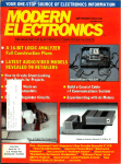

![VPC-1000 MANUAL [20090528]](http://vs1.manualzilla.com/store/data/005896865_1-4751a76ac00044adb338105a42e32db2-150x150.png)