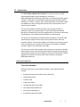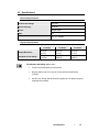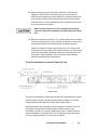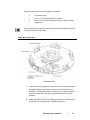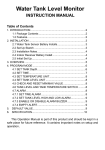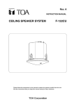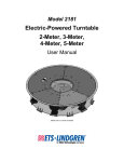
1
Model 2188
Turntable
1.2-m, 1.5-m, 2.0-m
User Manual
ETS-Lindgren L.P. reserves the right to make changes to any products herein to improve
functioning or design. Although the information in this document has been carefully reviewed and
is believed to be reliable, ETS-Lindgren does not assume any liability arising out of the
application or use of any product or circuit described herein; nor does it convey any license under
its patent rights nor the rights of others. All trademarks are the property of their respective
owners.
© Copyright 2005–2008 by ETS-Lindgren L.P. All Rights Reserved. No part of this
document may be copied by any means without written permission from
ETS-Lindgren L.P.
Trademarks used in this document: The ETS-Lindgren logo is a trademark of ETS-Lindgren L.P.;
WD-40 is a registered trademark of the WD-40 company.
Revision Record | MANUAL,TURNTABLES,2188 | Part #399771, Rev. C
Revision
Description
Date
A
Initial Release
November, 2005
B
Added two meter turntable information,
updated illustrations and drawings
January, 2006
C
Rebrand
July, 2008
ii
|
Table of Contents
Notes, Cautions, and Warnings .........................................................................v
1.0 Introduction ...................................................................................................7
Standard Configuration....................................................................................................... 7
Turntable Assembly ..................................................................................................... 7
Model 2090 Series Multi-Device Controller ........................................................................ 8
Optional Items..................................................................................................................... 8
Infrared Remote Controller .......................................................................................... 8
Additional Fiber Optic Cables ...................................................................................... 8
ETS-Lindgren Product Information Bulletin ........................................................................ 9
2.0 Maintenance ................................................................................................11
Recommended Maintenance Schedule ........................................................................... 11
Routine....................................................................................................................... 12
6-Month Service ......................................................................................................... 12
12-Month Service ....................................................................................................... 12
Replacement and Optional Parts...................................................................................... 13
Service Procedures .......................................................................................................... 13
3.0 Specifications..............................................................................................15
Electrical Specifications.................................................................................................... 15
Physical Specifications ..................................................................................................... 15
4.0 Turntable Installation Considerations.......................................................17
Before You Begin—Precautions....................................................................................... 17
Power and Signal Lines.................................................................................................... 18
Conduit....................................................................................................................... 18
Electrical Considerations ........................................................................................... 18
Access........................................................................................................................ 18
5.0 Electrical Installation ..................................................................................19
6.0 Assembly and Installation..........................................................................21
Required Tools ................................................................................................................. 21
Assembly Instructions....................................................................................................... 22
Floor Flange Installation in a Paneled Floor .............................................................. 25
Floor Flange Installation in a Concrete Pit................................................................. 26
|
iii
Motor Base Attachment .................................................................................................... 27
Post Installation Steps ...................................................................................................... 28
Final Level of Turntable ............................................................................................. 28
Conductive Grease Application.................................................................................. 28
7.0 Operation .....................................................................................................29
Model 2090 Series Multi-Device Controller ...................................................................... 29
Motor Base Status Indicators ........................................................................................... 29
Appendix A: Warranty ......................................................................................31
Appendix B: Drawings......................................................................................33
Appendix C: EC Declaration of Conformity ....................................................35
iv
|
Notes, Cautions, and Warnings
Note: Denotes helpful information intended to provide tips for
better use of the product.
Caution: Denotes a hazard. Failure to follow instructions
could result in minor personal injury and/or property
damage. Included text gives proper procedures.
Warning: Denotes a hazard. Failure to follow instructions
could result in SEVERE personal injury and/or property
damage. Included text gives proper procedures.
See the ETS-Lindgren Product Information Bulletin for safety, regulatory, and
other product marking information.
|
v
This page intentionally left blank.
vi
|
1.0 Introduction
The ETS-Lindgren Model 2188 Turntable is an electric-powered, variablespeed turntable platform system designed for use with the
Model 2090 Multi-Device Positioning Controller (or next generation ETS-Lindgren
controller, if applicable) to perform EMI compliance testing. The Model 2188 is
available in 1.2-meter, 1.5-meter, and 2.0-meter diameters. The turntable is ideal
for installations in new or existing test locations where pit excavation is not an
option or must be shallow.
The top of the turntable is conductive with a continuous ground brush to
electrically couple it to the ground plane. The ground brushes are attached
directly to the chamber floor by the floor flange and are in continuous contact with
the turntable top. The brushes point downward from the floor flange.
The drive motor and gearing are located beneath the platform. The Model 2188
is powered by an electric motor through a worm gear box with a chain and
sprocket final drive. The top of the turntable is removable to provide easy access
in the event that service is required. The electronics are located in a shielded
enclosure. Signal I/O is through fiber optic cable.
To prevent over-travel of the turntable in either direction of movement, hard limits
are provided in the form of pins that actuate switches located below the tabletop.
These pins allow limits to be set and allow as much as two full rotations. Rotation
speed can be varied from the front panel of the controller or through the
IEEE-488 interface bus.
Standard Configuration
TURNTABLE ASSEMBLY
Featuring continuous or non-continuous operation, the turntable assembly
includes:
•
Single-phase electric drive (208–230 VAC 50/60 Hz)
•
Variable-speed drive
•
Conductive top
•
Continuous rotation
•
10-meter fiber optic control cable
•
Fiber optic shield penetration kit
•
Fiber optic feedthroughs (2)
•
3-meter fiber optic control cable
Introduction
|
7
Model 2090 Series Multi-Device Controller
The Model 2090 Controller (or next generation ETS-Lindgren controller, if
applicable) is a separate component required for Model 2188 operation.
The controller can command two separate devices, such as ETS-Lindgren
towers and turntables, plus provide control of four auxiliary devices through a
fiber optic interface. The controller includes a GPIB bus and is compatible with
most popular EMI measurement software.
Optional Items
INFRARED REMOTE CONTROLLER
The Model 2188 is infrared compatible, and can be used with a universal remote
control programmed to a specific protocol, such as the ETS-Lindgren Infrared
Remote Controller (IR remote).
ADDITIONAL FIBER OPTIC CABLES
Additional lengths of fiber optic cable may be ordered.
8
|
Introduction
ETS-Lindgren Product Information Bulletin
See the ETS-Lindgren Product Information Bulletin included with your shipment
for the following:
•
Warranty information
•
Safety, regulatory, and other product marking information
•
Steps to receive your shipment
•
Steps to return a component for service
•
ETS Lindgren calibration service
•
ETS Lindgren contact information
Introduction
|
9
This page intentionally left blank.
10
|
Introduction
2.0 Maintenance
Before performing any maintenance, follow the safety
information in the ETS-Lindgren Product Information
Bulletin included with your shipment.
Regularly inspect all equipment and conduct scheduled
maintenance in accordance with the factory recommendations
provided.
WARRANTY
BEFORE SERVICING: CONTACT ETS-LINDGREN
(+1.512.531.6400)—Servicing or modifying the unit without
ETS-Lindgren authorization may void your warranty. If an
attempt to service the unit must be made, disconnect all
electrical power prior to beginning. Voltages exist at many points
within the instrument that could, if contacted, cause personal
injury. Only trained service personnel should perform
adjustments and/or service procedures upon this instrument.
Capacitors inside this instrument may still be charged even
when the instrument is disconnected from the power source.
Recommended Maintenance Schedule
Regular maintenance will prolong the effective operation and reliability of your
turntable. Follow the recommended schedule for routine, 6-month, and 12-month
service.
Do not perform maintenance while the turntable is operating.
Maintenance
|
11
ROUTINE
Routine maintenance should be conducted prior to each use of the turntable.
•
Remove foreign objects from between turntable top and
floor flange—Visually inspect the turntable prior to use, and look for foreign
objects in the gap between the turntable top and the floor flange. Remove the
objects, if possible.
•
Check for excessive rotation—Attempt to rotate the turntable top by hand.
Excessive rotation may indicate a loose drive component.
•
Listen for excessive noise—Listen for excessive or unusual noise during
turntable operation.
6-MONTH SERVICE
•
Lubricate the casters—Lubricate the casters with good quality bearing
grease.
•
Inspect the ground brush for contaminates—Vacuum the ground brush to
remove unwanted debris. If required, add a small amount of conductive
lubricant to the brush interface.
•
Inspect the ground brush for wear—Visually inspect the ground brush for
wear; if necessary, replace the ground brush.
12-MONTH SERVICE
12
•
Lubricate the main bearing race—Lubricate the main bearing race with a
grease gun containing good quality bearing grease. The grease fittings are
located inside the race, 90 degrees apart, beneath the top. Three discharges
from the grease gun in each fitting are adequate.
•
Lubricate the chain and sprocket of the chain drive—Apply good quality
grease to the chain and sprocket.
|
Maintenance
Replacement and Optional Parts
Following are the part numbers for ordering replacement or optional parts for the
Model 2188 Turntable.
Part Description
Part Number
Turntable Assembly
For a list of all turntable parts, see the
drawings located in the back pocket of
this manual.
IR Remote Controller
707030
Service Procedures
For the steps to return a system or system component to ETS-Lindgren for
service, see the Product Information Bulletin included with your shipment.
Maintenance
|
13
This page intentionally left blank.
14
|
Maintenance
3.0 Specifications
Electrical Specifications
Nominal AC Voltage:
230 VAC
Input Frequency:
50/60 Hz
Phase:
Single Phase
AMP:
2.0
RPM:
0.5 / 2.0 variable
Physical Specifications
1.2-meter
1.5-meter
2.0-meter
Height (Minimum):
16.51 cm
(6.12 in)
16.51 cm
(6.12 in)
16.51 cm
(6.12 in)
Distributed Load Rating:
500 kg
(1100 lb)
1000 kg
(2200 lb)
1000 kg
(2200 lb)
Distributed Load Rating applies when:
•
Load is evenly distributed to each section;
•
No point loads under 0.37 sq m (4.0 sq ft) should exceed 500 kg
(1100 lb);
•
And not over 400 kg (882 lb) should be applied to a 45-degree segment
outboard of the casters.
Specifications
|
15
This page intentionally left blank.
16
|
Specifications
4.0 Turntable Installation Considerations
Before assembling, installing, or connecting any components,
follow the safety information in the ETS-Lindgren
Product Information Bulletin included with your shipment.
Before You Begin—Precautions
Read this manual completely before starting installation. This
equipment should be installed and operated only by qualified
personnel.
Do not attempt to service unless qualified to do so. As with any
electrical equipment, make sure unit electrical power has been
disconnected and secured when performing scheduled
maintenance or adjustments.
Do not make any modifications to this unit without consulting
the factory directly.
WARRANTY
Regularly inspect all equipment for loose fasteners and wear.
Conduct scheduled maintenance in accordance with the factory
recommendations provided.
Only use replacement parts and fasteners ordered directly from
the factory.
Stay clear of all moving components on this equipment.
Do not operate turntable while someone is physically on the
turntable top.
Do not, at any time, place hands or feet in the vicinity of the
drive pinion on the turntable.
Turntable Installation Considerations
|
17
Power and Signal Lines
CONDUIT
Power and signal line paths should be planned in advance. Conduit should be in
place before pouring concrete or installing the ground plane. Consider the size of
the cable bundle when selecting conduit diameter.
ELECTRICAL CONSIDERATIONS
Electrical connection is subject to local electrical codes, and
should only be performed by a qualified electrician.
A qualified and licensed electrical contractor should install power lines, and the
installation should comply with all applicable regulatory agencies. A dedicated
circuit should be used, with the shortest distance possible between the power
source and the turntable.
For more information on electrical installation, see page 19.
ACCESS
An access area beneath the turntable is advisable for large diameter
installations. A service switch should be installed to deactivate the turntable
during service.
18
|
Turntable Installation Considerations
5.0 Electrical Installation
Before assembling, installing, or connecting any components,
follow the safety information in the ETS-Lindgren
Product Information Bulletin included with your shipment.
Electrical installation must be performed by a qualified
electrician, and in accordance with local and national electrical
standards.
Make sure the power is off and secured before proceeding.
The Model 2188 Turntable is configured to operate using 208-230 VAC,
single phase, 50/60 Hz service. This voltage level is recommended for operation
to reduce the surge currents necessary to power an electric motor.
1. The branch circuit supplying power to the motor base should be
protected from excess current according to local electrical codes. An
integral circuit breaker is mounted inside the main bearing on one of the
bearing support blocks. The circuit breaker is specifically designed for
the inductive load presented by the electric motor.
2. Make sure the conductor size is adequate for the motor load and the
distance from the mains source. Improperly sized conductors will lead to
a high voltage drop in the power conductors and cause reduced starting
torque and premature motor failure.
3. The motor base assembly is provided with a non-terminated flexible
conduit with input power leads exposed. The flexible conduit is to be
terminated into a junction box fitted on or near the motor base. Terminate
the power leads of the motor base assembly according to local electrical
code requirements. Following is the conductor color code:
Brown: AC high
Blue: AC neutral
Green/Yellow: Protective earth/safety ground
Electrical Installation
|
19
Connect the fiber optic control cable and install the power connection according
to local electrical code. See the controller manual for information on connecting
the fiber optic cable. After the fiber optic cable is installed, secure it with a wire tie
to one of the leveling screws.
To feed the fiber optic connectors through a waveguide in the chamber, cables
are included to connect from the feedthroughs on the penetration panel to the
controller and motor base.
20
|
Electrical Installation
6.0 Assembly and Installation
Before connecting any components, follow the safety information
in the ETS-Lindgren Product Information Bulletin included with
your shipment.
Prior to assembly and installation, review the drawings located in the back
pocket of this manual.
Proper installation of the turntable directly affects performance. The installation of
turntables two meters and larger will be performed by factory installation
specialists or individuals authorized by ETS-Lindgren to perform such work. The
following information is included only to provide an informational overview of the
installation process.
Required Tools
•
3/16-in Allen wrench
•
3/4-in pipe clamp ends
•
1/4-in Allen wrench
•
3/4-in pipe (about 6 feet;
length depends on turntable size)
•
3/8-in Allen wrench (3)
•
1 1/2-in C clamp (8)
•
6-mm Allen wrench
•
Measuring tape
•
3/8-in ratchet wrench
•
Pry bar
•
12-in crescent wrench
•
Level
•
15-mm, 12-point socket for
1/2-in square head screws
•
Square
•
7/16-in open/box end wrench
•
Hacksaw
•
1/2-in open/box end wrench
•
Black marker
•
3/4-in open/box end wrench
•
File
•
0.120 drill bit for 6–32 self-tapping
screws
•
WD-40®
•
#7 drill bit for 1/4–20 tap
•
Cutting oil
Assembly and Installation
|
21
•
3/8-in hand drill
•
Syringe to apply conductive grease
•
9/32 drill bit
•
Grease gun
•
#2 Phillips screw bit
•
Vacuum
•
#3 Phillips screw bit
•
1.2-in hammer drill
Assembly Instructions
Do not discard any packing material until the turntable is fully installed
and operational.
When working around the turntable, do not step on the
fiber optic connectors located on the motor base.
1. Uncrate all parts and check for shipping damage. Create a clear area to
safely assemble the turntable unit.
2. Verify that that fiber optic cable is long enough to reach from the
turntable to the control room.
3. If the turntable is to be installed in a pit, measure the depth and inside
diameter of the depth. Compare the measurements with the drawings
located in the back pocket of this manual.
The inner diameter of the pit should be as follows:
•
1.2-meter turntable—49.00 in (+/-0.25 in)
•
1.5-meter turntable—60.00 in (+/-0.25 in)
•
2.0-meter turntable—79.75 in (+/-0.25 in)
4. Remove the bolts that attach the top onto the turntable drive assembly;
these are the six flat-head bolts closest to center of the turntable top.
5. Remove the turntable top and place it in a safe location.
Only qualified personnel should use a forklift or other lifting
machinery.
22
|
Assembly and Installation
6. Using a forklift or other appropriate lifting machinery, place the turntable
bottom into position. The motor base with the fiber optic connectors
should point in the direction that the fiber optic cable will be installed.
This position will reduce the chance of the cable being kinked or twisted.
Make sure power is off and secured before proceeding.
Interior Design
Pit Locator Detail
Assembly and Installation
|
23
7. Position the turntable as close as possible to the center. Attach the
measuring bar to the brass spacers mounted onto the bearing; the
hole-mount locations are appropriate to the size of the turntable to be
installed.
Rotate the bearing and make sure approximately 7/8 in to 1 in spacing
exists between the edge of the outer measuring bar and the diameter of
hole cut into the pit. Adjust if necessary.
8. Once the center is located, mark around the perimeter of the
turntable base or outer floor plates. These marks may be used for
reference if the assembly moves during placement of the floor shims or
anchor plates.
When installing and positioning the turntable on modular shielding, make as
many anchor holes miss the floor joint strips as possible; use the shim plates
provided.
9. The Model 2188 Turntable includes curved floor anchor plates that are
under the base unit. The 1.5-m and 2.0-m models include an outer ring
of floor plates to support additional casters.
To ensure proper spacing, place the four connector strips (included)
between the base unit and outer plates. For placement and securing of
floor plates, see the Pit Locator Detail illustration on page 23 and the
drawings located in the back pocket of this manual.
If the turntable is to be installed into a welded chamber with a steel pit
and steel raised floor, see step 13.
10. The anchor plates are held in place by 1/4–20 screws and set collars.
Screw the anchor plates to the floor using #14x1-in #3 square socket
flat-head screws. Drill 1/8 in pilot holes for these screws and vacuum up
shavings so that you have good contact with the floor. Continue
mounting the rest of the plates.
11. Once all anchor plates are securely mounted, remove and discard the
1/4–20 screws that hold the anchor plates to the base.
12. Level the turntable to the raised floor.
24
|
Assembly and Installation
13. When mounting to a steel pit and steel raised floor, a #7 drill bit for
tapping or a 9/32 drill bit to create through holes is required when
mounting anchor plates to the steel raised floor. Locate and mark holes
in each group of anchor plates. Drill and tap or drill through each hole
and then screw in 1/4–20 hardware so that the turntable does not move
as you go around each location.
Before leveling, make sure all 1/2–13 flange nuts and clamp
collars are backed off completely to avoid pulling plates off the
floor.
14. Raise the turntable by turning the 1/2–13 square head screws clockwise
until the measuring bar top is 3/16 in above the raised floor; this is just a
rough finished height. Check the height with a leveling instrument.
When the turntable is leveled, tighten flange nuts on the square head
screws and secure set collars on the torque pins down onto the base top
surface and outer plate, if applicable. Remove the measuring bar. See
the Elevation View illustration in the next section and the drawings
located in the back pocket of this manual.
FLOOR FLANGE INSTALLATION IN A PANELED FLOOR
Elevation View
The ground ring assembly includes a floor flange with a mounted brush ring that
interfaces with the contact ring mounted beneath the turntable top. The floor
flange provides constant electrical contact with the ground plane.
Mounting methods vary according to user specifications. Clearance holes are
provided at evenly-spaced intervals along the outside perimeter of the
floor flange to attach to a customer supplied ground plane. These instructions
describe installation for a paneled floor. For concrete pit mounting instructions
see Floor Flange Installation in Concrete Pit on page 26.
Assembly and Installation
|
25
Installing the ground ring assembly requires these tools:
•
1/4-in spacers (3)
•
5/32-in drill bit
•
Hand drill
•
#3 Phillips drive bit
•
#14 x 1 wood/metal screws
•
Small square
The turntables have two floor flange pieces. All flanges are pre-cut at the factory
for a drop-in fit.
1. Lay the floor flange into the opening of the raised floor and push outward
to the diameter of the opening.
2. Attach the turntable top to the brass spacers with the hardware provided.
3. Using a pipe clamp and 1/4-in Allen wrenches or 1/4-in pin, place a
spacer between the turntable and floor flange starting in three places in
the center or on the flange.
4. Once tension is placed on all three wrenches, drill a 5/32-in hole through
the counter-sunk holes in the floor flange. Drill completely through the
panel and place screws into the holes.
5. Continue working around the floor flange, completing two or three holes
at a time.
Make sure that a 1/4-in gap between the turntable top and the mounted brush
ring be held as close as possible so that the grounding brushes seat properly.
Also, make sure the flange ends are flush with each other.
6. Continue mounting until all screws are installed. Some screws may fall
between the floor panel joints. Try to position the flanges, making sure as
few screws hit these points as possible, and making sure that the first or
last hole in the flange is not too close to one of these joints. Trim the top
floor joint strips to fit up against the flange.
FLOOR FLANGE INSTALLATION IN A CONCRETE PIT
Installing in a concrete pit is the same as a paneled floor, with the exception of
the mounting hardware. Instead of the #14 x 1-in square socket flat head screws,
use 1/4 x 1-3/4-in Phillips flat head concrete anchors.
26
|
Assembly and Installation
These tools are required for the next stage of installation:
•
1/2-in hammer drill
•
3/16 x 3 1/2-in hammer drill bit, at minimum
•
Vacuum to clean inside the drilled holes for maximum thread
engagement
When drilling holes, be aware of buried conduit and pit drainpipes. Drill 3/16-in
holes, two inches minimum depth.
Motor Base Attachment
Turntable Motor Base
1. Locate the box that contains the motor base. The box also includes the
hardware needed to attach the motor base to the turntable. See the
illustration, Turntable Motor Base, to locate the drive chain and bolts to
secure the motor base. Slide the motor base between the two rails
provided.
2. Attach three bolts, flat and lock washers (provided) on each side of the
motor base. Do not tighten them completely at this time.
Assembly and Installation
|
27
3. Attach the chain around the bearing sprocket and the drive sprocket.
Adjust the motor base using the two pusher bolts provided. Allow only
1/4-in maximum side-to-side motion for proper chain tension on the
motor.
4. Tighten the six securing bolts.
Post Installation Steps
FINAL LEVEL OF TURNTABLE
Once the turntable is in place with the floor flange and wear strip mounted, check
that the table is level. Verify that it is level and all screws, nuts, and collars are
tightened.
CONDUCTIVE GREASE APPLICATION
Before placing the turntable into operation, apply conductive grease to the
ground brush. Apply the contents of one tube of conductive grease to the brush.
Apply one tube per meter size of the diameter of the turntable.
28
|
Assembly and Installation
7.0 Operation
Before placing into operation, follow the safety information in the
ETS-Lindgren Product Information Bulletin included with your
shipment.
Model 2090 Series Multi-Device Controller
With the assembly of the turntable complete, the Model 2090 Multi-Device
Controller (or next generation ETS Lindgren controller, if applicable) must be
connected to the unit and power applied to both the motor base and controller.
See the controller manual for complete information on connecting the fiber optic
cable and operating the controller. A manual is included with each controller and
is also available for download from www.ets-lindgren.com.
Motor Base Status Indicators
Following are actions of the status indicators when used with the Infrared
Remote Controller (IR remote). For more information on the IR remote, see
page 8.
State
1
2
3
4
Power
Any
Any
Any
Any
Cycling
Init
Up/CW
Amber
Green
Green
Down/CCW
Green
Polar
Upper Limit
Lower Limit
Red
Red
Operation
|
29
This page intentionally left blank.
30
|
Operation
Appendix A: Warranty
See the Product Information Bulletin included with your shipment for the
complete ETS-Lindgren warranty for your Model 2188.
DURATION OF WARRANTIES FOR MODEL 2188
All product warranties, except the warranty of title, and all remedies for warranty
failures are limited to two years.
Product Warranted
Duration of Warranty Period
Model 2188 Turntable
2 Years
Warranty
|
31
This page intentionally left blank.
32
|
Warranty
Appendix B: Drawings
These drawings are located in the back pocket of this manual:
Drawing Description
Drawing Number
1.2m, With Ground Ring (2 pages)
2188-1.23
1.5m, With Ground Ring (2 pages)
2188-1.53
2m, With Ground Ring (2 pages)
2188-2.03
2188-1.23 (2 pages)
108912
2188-1.23, Sub-Assembly, Top
110053
2188-1.53, Sub-Assembly, Top
110277
2188-2.03, Sub-Assembly, Top
110406
2188 Limit Switch, Instructions
398790
Drawings
|
33
This page intentionally left blank.
34
|
Drawings
Appendix C: EC Declaration of Conformity
EC Declaration of Conformity
|
35
REF DRAWING
REVISIONS
NOTES:
1. REFER TO SUB-ASSY'S AND KITS FOR PARTS USED TO
ASSEMBLE AND INSTALL TURNTABLE
DESCRIPTION
DATE
ECO#
REV
4634
A
INITIAL RELEASE
5003
B
UPDATED PER MODS ON 108913,108914,
108922, AND 108915
APPROVED
8/18/05
AR
RBG
12/9/05
FLOOR LEVEL
51.73 REF
WOOD/METAL SCREWS
SEE SHIPPING KIT
47.13 TABLE TOP
.25 GAP BETWEEN TABLE TOP
AND BRUSH HOLDER
TABLE TOP
2
BRUSH HOLDER ASSY
SEE TURNTABLE TOP
SUB-ASSY
FLOOR FLANGE
SEE TURNTABLE TOP
SUB-ASSY
1
A
SECTION A-A
SCALE 1 : 2
A
48.10 REF
3
1
110033
KIT,SHIPPING,2188-1.23 (NOT SHOWN)
2
1
110053
SUB-ASSY,TOP,TURNTABLE,2188-1.23
1
1
108912
TURNTABLE,ASSY,2188-1.23
ITEM NO.
QTY.
PART NUMBER
5.88
.12 REF
DESCRIPTION
ETS LINDGREN
EMC Test Systems, L.P.
Cedar Park, TX
UNLESS OTHERWISE SPECIFIED:
DIMENSIONS ARE IN INCHES
TOLERANCES ARE:
DECIMALS
ANGLES
X.XX ± .015
X.XXX ± .005
± .5
APPROVALS
DRAWN
CHECKED
RBG
6/15/05
SRK
6/22/05
MATERIAL
FINISH
NONE
DATE
SEE BOM
TM
An ESCO Technologies Company
Lindgren-RF Enclosures
Glendale Hts, IL
TITLE
TURNTABLE,LIGHT DUTY,1.2m W/GND RING
PROPRIETARY INFORMATION
ANY DUPLICATION OF THIS
DOCUMENT, WHOLE OR IN PART,
WITHOUT EXPRESS WRITTEN
PERMISSION OF ETS LINDGREN
IS PROHIBITED.
SIZE SCALE
D
DWG. NO.
1:4
DO NOT SCALE DRAWING
REV.
2188-1.23
SHEET
1
OF
B
2
REF DRAWING
REVISIONS
ECO#
NOTES:
DESCRIPTION
REV
DATE
APPROVED
LOOSEN AND DISCARD 1/4-20
SCREWS PRIOR TO ADJUSTING
BASE PLATE VERTICALLY.
(3 PLACES)
LOOSEN CLAMP COLLARS PRIOR
TO ADJUSTING ASSY VERTICALLY
8 PLACES
LOOSEN NUT PRIOR TO
ADJUSTING ASSY VERTICALLY
13 PLACES.
LOCATE AND CENTER TABLE ASSY
THEN SECURE FLOOR PLATES AND PADS
TO FLOOR WITH PROPER FASTENERS
PRIOR TO ADJUSTING ASSY VERTICALLY.
ITEM#
PART#
QTY
DESCRIPTION
ETS LINDGREN
EMC Test Systems, L.P.
Cedar Park, TX
UNLESS OTHERWISE SPECIFIED:
DIMENSIONS ARE IN INCHES
TOLERANCES ARE:
DECIMALS
ANGLES
X.XX ± .015
X.XXX ± .005
± .5
APPROVALS
DRAWN
CHECKED
RBG
6/15/05
SRK
6/22/05
MATERIAL
FINISH
NONE
DATE
SEE BOM
TM
An ESCO Technologies Company
Lindgren-RF Enclosures
Glendale Hts, IL
TITLE
TURNTABLE,LIGHT DUTY,1.2m W/GND RING
PROPRIETARY INFORMATION
ANY DUPLICATION OF THIS
DOCUMENT, WHOLE OR IN PART,
WITHOUT EXPRESS WRITTEN
PERMISSION OF ETS LINDGREN
IS PROHIBITED.
SIZE SCALE
D
DWG. NO.
1:4
DO NOT SCALE DRAWING
REV.
2188-1.23
SHEET
2
OF
B
2
REF DRAWING
REVISIONS
ECO#
NOTES:
1. REFER TO SUB-ASSY'S AND KITS FOR PARTS USED TO
ASSEMBLE AND INSTALL TURNTABLE
62.73 REF
PART 910682 FROM SHIPPING KIT
58.13 TABLE TOP
DESCRIPTION
REV
DATE
APPROVED
1
INITIAL BUILD
XX-XX-XX
XX
2
UPDATED PER MODS ON 108912
12/16/05
RG
FLOOR LEVEL
1
.25 GAP BETWEEN TABLE TOP
AND BRUSH HOLDER
REFER TO MANUAL FOR PIT
OPENING DIMENSION
PART 109468 FROM TOP
SUB-ASSY
PART 705420 FROM SHIPPING
KIT
A
A
2
59.10 REF
SECTION A-A
SCALE 1 : 2
.12 REF
± .5
APPROVALS
DRAWN
RBG
KIT,SHIPPING,2188-1.53 (NOT SHOWN)
2
1
108912
TURNTABLE,ASSY,2188-1.23
1
1
110277
SUB-ASSY,TOP,TURNTABLE,2188-1.53
ITEM#
PART#
QTY
DESCRIPTION
DATE
9/12/05
TM
An ESCO Technologies Company
Lindgren-RF Enclosures
Glendale Hts, IL
TITLE
TURNTABLE,LIGHT DUTY,1.5m W/GND RING
CHECKED
PROPRIETARY INFORMATION
MATERIAL
NONE
110276
EMC Test Systems, L.P.
Cedar Park, TX
UNLESS OTHERWISE SPECIFIED:
DIMENSIONS ARE IN INCHES
TOLERANCES ARE:
DECIMALS
ANGLES
FINISH
1
ETS LINDGREN
5.88
X.XX ± .015
X.XXX ± .005
3
SEE BOM
ANY DUPLICATION OF THIS
DOCUMENT, WHOLE OR IN PART,
WITHOUT EXPRESS WRITTEN
PERMISSION OF ETS LINDGREN
IS PROHIBITED.
SIZE SCALE
D
DWG. NO.
1:4
DO NOT SCALE DRAWING
REV.
2188-1.53
SHEET
1
OF
2
2
REF DRAWING
REVISIONS
ECO#
NOTES:
DESCRIPTION
REV
1
APPROVED
XX-XX-XX
INITIAL BUILD
MOTORBASE, SEE 108912
FOR HARDWARE AND MOTORBASE
LOCATION AND INSTALLATION
LOCATE AND CENTER TABLE ASSY
THEN SECURE FLOOR PLATES AND PADS
TO FLOOR WITH PROPER FASTENERS
PRIOR TO ADJUSTING ASSY VERTICALLY
DATE
XX
LOOSEN AND DISCARD 1/4-20
SCREWS PRIOR TO ADJUSTING
ASSY VERTICALLY
19 PLACES
LOOSEN NUT PRIOR TO
ADJUSTING ASSY VERTICALLY
29 PLACES
LOOSEN CLAMP COLLAR PRIOR
TO ADJUSTING ASSY VERTICALLY
8 PLACES
ETS LINDGREN
EMC Test Systems, L.P.
Cedar Park, TX
UNLESS OTHERWISE SPECIFIED:
DIMENSIONS ARE IN INCHES
TOLERANCES ARE:
DECIMALS
ANGLES
X.XX ± .015
X.XXX ± .005
± .5
APPROVALS
DRAWN
RBG
NONE
9/12/05
An ESCO Technologies Company
Lindgren-RF Enclosures
Glendale Hts, IL
TITLE
TURNTABLE,LIGHT DUTY,1.5m W/GND RING
CHECKED
PROPRIETARY INFORMATION
MATERIAL
FINISH
DATE
TM
SEE BOM
ANY DUPLICATION OF THIS
DOCUMENT, WHOLE OR IN PART,
WITHOUT EXPRESS WRITTEN
PERMISSION OF ETS LINDGREN
IS PROHIBITED.
SIZE SCALE
D
DWG. NO.
1:6
DO NOT SCALE DRAWING
REV.
2188-1.53
SHEET
2
OF
2
2
REF DRAWING
REVISIONS
ECO#
NOTES:
1. REFER TO SUB-ASSY'S AND KITS FOR PARTS USED TO
ASSEMBLE AND INSTALL TURNTABLE
82.48 REF
DESCRIPTION
REV
FLOOR LEVEL
1
DATE
APPROVED
XX-XX-XX
INITIAL BUILD
XX
77.88 TABLE TOP
PART 910682 FROM SHIPPING KIT
1
.25 GAP BETWEEN TABLE TOP
AND BRUSH HOLDER
REFER TO MANUAL FOR PIT
OPENING DIMENSION
PART 109468 FROM TOP
SUB-ASSY
2
A
PART 705421 FROM SHIPPING
KIT
A
82.48 REF
SECTION A-A
SCALE 1 : 2
5.88
.12 REF
3
1
110407
KIT,SHIPPING,2188-2.03
2
1
108912
TURNTABLE,ASSY,2188-1.23
1
1
110406
SUB-ASSY,TOP,TURNTABLE,2188-2.03
ITEM#
QTY
PART#
DESCRIPTION
ETS LINDGREN
EMC Test Systems, L.P.
Cedar Park, TX
UNLESS OTHERWISE SPECIFIED:
DIMENSIONS ARE IN INCHES
TOLERANCES ARE:
DECIMALS
ANGLES
X.XX ± .015
X.XXX ± .005
FINISH
NONE
± .5
APPROVALS
DRAWN
RBG
DATE
11/17/05
TM
An ESCO Technologies Company
Lindgren-RF Enclosures
Glendale Hts, IL
TITLE
TURNTABLE,LIGHT DUTY,2m W/GND RING
CHECKED
PROPRIETARY INFORMATION
MATERIAL
SEE BOM
ANY DUPLICATION OF THIS
DOCUMENT, WHOLE OR IN PART,
WITHOUT EXPRESS WRITTEN
PERMISSION OF ETS LINDGREN
IS PROHIBITED.
SIZE SCALE
D
DWG. NO.
1:6
DO NOT SCALE DRAWING
REV.
2188-2.03
SHEET
1
OF
1
2
REF DRAWING
REVISIONS
ECO#
NOTES:
DESCRIPTION
REV
1
DATE
APPROVED
XX-XX-XX
INITIAL BUILD
XX
LOOSEN NUT PRIOR TO
ADJUSTING ASSY VERTICALLY
37 PLACES
LOOSEN CLAMP COLLAR PRIOR
TO ADJUSTING ASSY VERTICALLY
20 PLACES
MOTORBASE, SEE 108912
FOR HARDWARE AND MOTORBASE
LOCATION AND INSTALLATION
LOOSEN AND DISCARD 1/4-20
SCREWS PRIOR TO ADJUSTING
ASSY VERTICALLY 24 PLACES
LOCATE AND CENTER TABLE ASSY
THEN SECURE FLOOR PLATES AND PADS
TO FLOOR WITH PROPER FASTENERS
PRIOR TO ADJUSTING ASSY VERTICALLY
ETS LINDGREN
EMC Test Systems, L.P.
Cedar Park, TX
UNLESS OTHERWISE SPECIFIED:
DIMENSIONS ARE IN INCHES
TOLERANCES ARE:
DECIMALS
ANGLES
X.XX ± .015
X.XXX ± .005
± .5
DATE
APPROVALS
DRAWN
RBG
11/17/05
NONE
An ESCO Technologies Company
Lindgren-RF Enclosures
Glendale Hts, IL
TITLE
TURNTABLE,LIGHT DUTY,2m W/GND RING
CHECKED
PROPRIETARY INFORMATION
MATERIAL
FINISH
TM
SEE BOM
ANY DUPLICATION OF THIS
DOCUMENT, WHOLE OR IN PART,
WITHOUT EXPRESS WRITTEN
PERMISSION OF ETS LINDGREN
IS PROHIBITED.
SIZE SCALE
D
DWG. NO.
1:6
DO NOT SCALE DRAWING
REV.
2188-2.03
SHEET
2
OF
1
2
REF DRAWING
REVISIONS
NOTES:
APPROVED
RELEASED
3/25/05
DM
B
REMOVED P/N'S 108920,108925,880280,
910373,910241,910682,890706,930993,
920016,920250,399253,890440,109333,
109465,109468,910714,705417,910159
8/18/05
AR
C
UPDATED PER MODS ON 108913,108914,
108922, AND 108915
12/9/05
RG
REV
4602
A
4634
5003
1. NOT ALL PARTS SHOWN. SEVERAL ITEMS USED AND LOCATED AT ASSY.
DESCRIPTION
5
27
1
DATE
ECO#
10
9
2
37
21
25
11
13
26
3
A
A
4
18
46
45
44
43
42
41
40
39
38
37
36
35
34
33
32
31
30
29
28
27
26
25
24
23
22
21
20
19
18
17
16
15
14
13
12
11
10
9
8
7
6
5
4
3
2
1
ITEM NO.
22
15.06
12
16
33
7
39
32
38
23
31
33
20
20
9
10
35
6
2
37
1
40
*
19
34
24
22
28
8
29
14
6
1
1
20
4
4
.1
1
4
4
10
6
14
2
7
1
1
6
1
1
8
8
6
2
1
26
6
8
14
24
2
13
3
4
8
13
8
2
2
1
2
2
6
6
1
1
1
QTY.
670024
920203
890983
708040
920228
920081
890005
910449
910244
890004
910414
910763
910901
910436
108758
109307
108924
105012
109040
910536
910752
910820
910664
910228
910411
910418
910762
910393
910788
910718
910367
108915
108916
890860
890238
108922
108914
108913
880180
108921
108918
108923
880279
108919
109367
108917
PART NUMBER
ETS LINDGREN
EMC Test Systems, L.P.
Cedar Park, TX
UNLESS OTHERWISE SPECIFIED:
DIMENSIONS ARE IN INCHES
TOLERANCES ARE:
DECIMALS
ANGLES
3
SECTION A-A
POWER CORD 15A 220V IEC-320 BELDEN 17569(N/S)
LABEL CE MARK (N/S)
SLEEVING,SLIT-CONVOLUTED,PE,1/4" I.D. (N/S)
FIBER OPTIC CABLE LIMIT SWITCH 1.5M (N/S)
LABEL-EQUIPMENT CHECKED (N/S)
LOCTITE THREAD LOCKING #242 31 50MI (N/S)
LINK CONNECTING 41 CL MARTIN
SCREW HEX HEAD SS 1/4-20 X 1 1/4
SCREW,8-32 X 3/8,PHIL,BIND
ROLLER CHAIN NICKEL PLATE 41 MARTIN
SCREW HEX HEAD CAP G. 5 1/2-13 X 1 1/4
SCREW,HEX HD,5/16 X 1.25"
SCREW,1/4-20 X 2,HEX,CAP,SS,FULL THRD
BOLT,1/4-20 X 1/2,HEX,SS
ASSY,MECHANICAL LIMIT SWITCH,MOTORBASE
BRACKET,LIMIT SWITCH CASE
SPACER,TABLE TOP
KEY .187 X .875
ASSY,MOTORBASE,2188
SCREW FLAT HEAD SOCKET 1/2-13 X 1 1/2
SCREW,SKT FLT HEAD SS 3/8-16 X 1 1/4
NUT,1/2-13,HEX,SS
HEX NUT, STAINLESS 1/4-20
WASHER SPLIT LOCK SS #8
WASHER,3/8,LOCK,SPLIT,STL,ZN
WASHER,1/2",LOCK,STL,SPLT
LOCKWASHER,SPLIT,1/4",SS
WASHER,5/16,LOCK,STL,ZINC,SPLT
BOLT.3/8-16 X 1-1/4" HX HD CAP GR5
SCREW,HEX HD CAP,3/8-16 X 2.5
HEX NUT SERRATED FLANGE ZINC 1/2-13
PAD,FLOOR,INNER
MOUNT,SUPPORT,BEARING PLATE
SHAFT COLLAR,7/8 BORE,ONE PIECE,ALUM
SCREW LEVELING 1/2-13 X 3 SQ HD CU
POST,TORQUE STOP
FLOOR PLATE,OUTER,QTR 2&4
FLOOR PLATE,OUTER,QTR 1&3
SPROCKET,1/2" PITCH,12T,7/8" BORE
BLOCK,PUSHER BOLT
BAR,MOUNTING,MOTORBASE
SPACER,CASTER
CASTER,RIGID,3-1/4 X 2
BASE,TURNTABLE
ASSY,BEARING,TURNTABLE,2188
PLATE,BEARING MOUNT
DESCRIPTION
X.XX ± .015
X.XXX ± .005
FINISH
NONE
± .5
APPROVALS
DRAWN
CHECKED
DATE
RBG
5/14/04
SRK
01/26/05
MATERIAL
SEE BOM
TM
An ESCO Technologies Company
Lindgren-RF Enclosures
Glendale Hts, IL
TITLE
TURNTABLE,2188-1.23
PROPRIETARY INFORMATION
ANY DUPLICATION OF THIS
DOCUMENT, WHOLE OR IN PART,
WITHOUT EXPRESS WRITTEN
PERMISSION OF ETS LINDGREN
IS PROHIBITED.
SIZE SCALE
D
DWG. NO.
1:4
DO NOT SCALE DRAWING
REV.
108912
SHEET
1
OF
C
2
REF DRAWING
REVISIONS
ECO#
NOTES:
DESCRIPTION
REV
DATE
APPROVED
10
9
15
10
9
BOTTOM VIEW
ETS LINDGREN
EMC Test Systems, L.P.
Cedar Park, TX
UNLESS OTHERWISE SPECIFIED:
DIMENSIONS ARE IN INCHES
TOLERANCES ARE:
DECIMALS
ANGLES
X.XX ± .015
X.XXX ± .005
± .5
APPROVALS
DRAWN
CHECKED
RBG
5/14/04
SRK
01/26/05
MATERIAL
FINISH
NONE
DATE
SEE BOM
TM
An ESCO Technologies Company
Lindgren-RF Enclosures
Glendale Hts, IL
TITLE
TURNTABLE,2188-1.23
PROPRIETARY INFORMATION
ANY DUPLICATION OF THIS
DOCUMENT, WHOLE OR IN PART,
WITHOUT EXPRESS WRITTEN
PERMISSION OF ETS LINDGREN
IS PROHIBITED.
SIZE SCALE
D
DWG. NO.
1:4
DO NOT SCALE DRAWING
REV.
108912
SHEET
2
OF
C
2
REF DRAWING
REVISIONS
NOTES:
REV
4634
A
INITIAL RELEASE
B
ADDED P/N 109468,705417,910652
1. EDGES AND CORNERS OF ITEM 5 TO BE BENT IN TOWARDS CENTER OF TABLE (8 PLACES)
MIN. 30 DEGREES AFTER ATTACHING TO UNDERSIDE OF TABLE TOP WITH ITEM 12.
9
DESCRIPTION
ECO#
DATE
APPROVED
8/18/05
AR
-
-
1
3
10
2
.50 REF
SEE NOTE 1
7
5
8
4
6
12
75
910714
SCREW,6-32 X 1/4",PHIL,ZN,PAN,TAPTITE
11
50
910652
SCREW FH PHL ZN TAPTITE 6-32 X 3/8
10
4
910241
SCREW FLAT HEAD 8-32 X 3/8
9
8
910930
SCREW,10-32 X 3/8.PHIL,FLAT,SS
8
6
110059
PLUG,HOLE,TABLE TOP
7
2
705417
FLOOR FLANGE,TURNTABLE,1.2m,AL
6
4
109468
ASSY,BRUSH/HOLDER,MODIFICATION
5
4
109333
CONTACT STRIP,BRUSH,TURNTABLE
4
6
910373
SOCKET HEAD FLAT SS 5/16-18 X 1
3
2
880280
PIN,CLEVIS,SS,1/2"O.D. X 1" LONG
2
1
108925
COVER,ACCESS
1
1
108920
TOP,TURNTABLE
ITEM NO.
QTY.
PART NUMBER
11
12
REF,USE AT FINAL ASSY
DESCRIPTION
ETS LINDGREN
An ESCO Technologies Company
EMC Test Systems, L.P.
Cedar Park, TX
UNLESS OTHERWISE SPECIFIED:
DIMENSIONS ARE IN INCHES
TOLERANCES ARE:
DECIMALS
ANGLES
X.XX ± .015
X.XXX ± .005
± .5
APPROVALS
DRAWN
CHECKED
RBG
6/16/05
SRK
6/22/05
MATERIAL
FINISH
NONE
DATE
SEE BOM
TM
Lindgren-RF Enclosures
Glendale Hts, IL
TITLE
SUB-ASSY,TOP,TURNTABLE,2188-1.23
PROPRIETARY INFORMATION
ANY DUPLICATION OF THIS
DOCUMENT, WHOLE OR IN PART,
WITHOUT EXPRESS WRITTEN
PERMISSION OF ETS LINDGREN
IS PROHIBITED.
SIZE SCALE
D
DWG. NO.
1:3
DO NOT SCALE DRAWING
REV.
110053
SHEET
1
OF
B
1
REF DRAWING
REVISIONS
ECO#
NOTES:
1. EDGES AND CORNERS OF ITEM 7 TO BE BENT IN TOWARDS CENTER OF TABLE (10 PLACES)
MIN. 30 DEGREES AFTER ATTACHING TO UNDERSIDE OF TABLE TOP WITH ITEM 22.
11
12
6
15
8
DESCRIPTION
REV
DATE
APPROVED
1
INITIAL BUILD
XX-XX-XX
XX
2
REPLACED 910678 WITH 890238
12/16/05
RG
13
14
7
9
21
22
SEE NOTE 1
10
3
2
23
18
1
5
19
16
17
17
4
890238
910652
910714
910436
910402
910367
910411
910788
910373
110059
910241
910930
SCREW LEVELING 1/2-13 X 3 SQ HD CU
SCREW FH PHL ZN TAPTITE 6-32 X 3/8
SCREW,6-32 X 1/4",PHIL,ZN,PAN,TAPTITE
BOLT,1/4-20 X 1/2,HEX,SS
SCREW HEX HEAD 3/8-16 X 3/4
HEX NUT SERRATED FLANGE ZINC 1/2-13
WASHER,3/8,LOCK,SPLIT,STL,ZN
BOLT.3/8-16 X 1-1/4" HX HD CAP GR5
SOCKET HEAD FLAT SS 5-16-18 X 1
PLUG,HOLE,TABLE TOP
SCREW FLAT HEAD 8-32 X 3/8
SCREW,10-32 X 3/8.PHIL,FLAT,SS
11
10
9
8
7
6
5
2
5
2
1
5
1
8
880280
109468
705420
108925
109333
110278
880279
PIN,CLEVIS,SS,1/2"O.D. X 1" LONG
ASSY,BRUSH/HOLDER,MODIFICATION
FLOOR FLANGE,TURNTABLE,1.5m,AL
COVER,ACCESS
CONTACT STRIP,BRUCH,TURNTABLE
TOP,TURNTABLE,1.5m
CASTER,RIGID,3-1/4X 2
4
3
8
8
108923
110280
SPACER,CASTER
FLOOR PLATE,CASTER,OUTER ROW
2
1
8
4
110279
106943
TIE PLATE,CASTER,OUTER ROW
CASTER STRUT BAR, 2088
ITEM NO.
QTY.
PART NUMBER
DESCRIPTION
± .5
APPROVALS
DRAWN
RBG
DATE
9/12/05
TM
An ESCO Technologies Company
EMC Test Systems, L.P.
Cedar Park, TX
UNLESS OTHERWISE SPECIFIED:
DIMENSIONS ARE IN INCHES
TOLERANCES ARE:
DECIMALS
ANGLES
FINISH
16
60
90
16
8
16
40
32
6
6
4
8
ETS LINDGREN
20
X.XX ± .015
X.XXX ± .005
23
22
21
20
19
18
17
16
15
14
13
12
Lindgren-RF Enclosures
Glendale Hts, IL
TITLE
SUB-ASSY,TOP,TURNTABLE,2188-1.53
CHECKED
PROPRIETARY INFORMATION
MATERIAL
SEE BOM
ANY DUPLICATION OF THIS
DOCUMENT, WHOLE OR IN PART,
WITHOUT EXPRESS WRITTEN
PERMISSION OF ETS LINDGREN
IS PROHIBITED.
SIZE SCALE
D
DWG. NO.
1:4
DO NOT SCALE DRAWING
REV.
110277
SHEET
1
OF
2
1
REF DRAWING
REVISIONS
ECO#
NOTES:
1. EDGES AND CORNERS OF ITEM 15 TO BE BENT IN TOWARDS CENTER OF
TABLE (12 PLACES) MIN. 30 DEGREES AFTER ATTACHING TO UNDERSIDE
OF TABLE TOP PIECES WITH ITEM 32.
3
19
23
1
24
DESCRIPTION
REV
DATE
1
INITIAL BUILD
XX-XX-XX
2
REVISED PER CHANGES TO 2188-1.23
12/9/05
2
4
25
APPROVED
XX
RBG
31
9
14
29
5
15
34
33
32
31
30
29
28
27
26
25
24
23
22
21
20
19
18
17
16
15
14
13
12
11
10
9
8
7
6
5
4
3
2
1
ITEM NO.
32
17
8
26
27
28
16
21
34
27
10
13
7
22
20
33
18
48
24
108
18
12
12
8
56
8
4
8
6
24
74
24
6
12
2
6
6
6
12
12
12
4
1
12
12
12
9
1
1
1
2
QTY
910788
910436
910714
910413
910752
910173
910402
910411
910407
910241
910930
910373
890238
910652
910367
110059
110280
705421
109468
109333
110405
890860
110404
108922
110402
110399
880279
108923
110403
105813
108925
110401
110400
880280
PART NUMBER
BOLT.3/8-16 X 1-1/4" HX HD CAP GR5
BOLT,1/4-20 X 1/2,HEX,SS
SCREW,6-32 X 1/4",PHIL,ZN,PAN,TAPTITE
SCREW FLAT HEAD SOCKET 1/2-13 X 1
SCREW,3/8-16 X 1-1/4,SH,FLAT,SS
SCREW FLAT HEAD 6-32 X 3/8
SCREW HEX HEAD 3/8-16 X 3/4
WASHER,3/8,LOCK,SPLIT,STL,ZN
WASHER,3/8,FLAT,STL,ZN
SCREW FLAT HEAD 8-32 X 3/8
SCREW,10-32 X 3/8.PHIL,FLAT,SS
SOCKET HEAD FLAT SS 5/16-18 X 1
SCREW LEVELING 1/2-13 X 3 SQ HD CU
SCREW FH PHL ZN TAPTITE 6-32 X 3/8
HEX NUT SERRATED FLANGE ZINC 1/2-13
PLUG,HOLE,TABLE TOP
FLOOR PLATE,CASTER,OUTER ROW
FLOOR FLANGE,TURNTABLE,2.03m,AL
ASSY,BRUSH/HOLDER MODIFICATION
CONTACT STRIP,BRUSH,TURNTABLE
CONTACT FLAT,BRUSH,TURNTABLE
SHAFT COLLAR,7/8 BORE,ONE PIECE,ALUM
MOUNT,TORQUE PIN
POST,TORQUE STOP
BAR,STRUT,14.00"
TOP,SECTION 1,TURNTABLE,2.03m
CASTER,RIGID,3 -1/4 X 2
SPACER,CASTER
TIEPLATE,CASTER,OUTER
TAB,TOP,2087
COVER,ACCESS
TOP,SECTION 3,TURNTABLE,2.03m
TOP,SECTION 2,TURNTABLE,2.03m
PIN,CLEVIS,SS,1/2"O.D. X 1" LONG
DESCRIPTION
ETS LINDGREN
An ESCO Technologies Company
EMC Test Systems, L.P.
Cedar Park, TX
12
11
30
UNLESS OTHERWISE SPECIFIED:
DIMENSIONS ARE IN INCHES
TOLERANCES ARE:
DECIMALS
ANGLES
X.XX ± .015
X.XXX ± .005
FINISH
NONE
± .5
APPROVALS
DRAWN
RBG
DATE
11/21/05
TM
Lindgren-RF Enclosures
Glendale Hts, IL
TITLE
SUB-ASSY,TOP,TURNTABLE,2188-2.03
CHECKED
PROPRIETARY INFORMATION
MATERIAL
SEE BOM
ANY DUPLICATION OF THIS
DOCUMENT, WHOLE OR IN PART,
WITHOUT EXPRESS WRITTEN
PERMISSION OF ETS LINDGREN
IS PROHIBITED.
SIZE SCALE
D
DWG. NO.
1:6
DO NOT SCALE DRAWING
REV.
110406
SHEET
1
OF
2
1
REF DRAWING
REVISIONS
STEP 3:
NOTES:
THIS CONFIGURATION ALLOWS THE TURNTABLE
TO ROTATE -45 COUNTER CLOCKWISE
AND 405 CLOCKWISE
CCW
CW
*1 & 2
-42
360
1&3
-45
405
4&8
-90
450
7&5
-135
495
7&6
-135
540
1
-45
1035
2
-360
720
3
-315
765
4
-270
810
5
-225
855
6
-180
900
7
-135
945
8
-90
990
DESCRIPTION
REV
1
POSITION PINS IN THESE
HOLES
5
PIN
POSITION
ECO#
DATE
APPROVED
XX
WSW
INITIAL RELEASE
STEP 4:
SET 2090 CURRENT POSITION TO 0.0
IF DESIRED, PUT ANY USER MARKINGS ON TURNTABLE
4
*ONLY FOR PIN POSITION 1 & 2
PLACE PIN ON THIS
SIDE OF LIMIT SWITCH
ASSY
6
LIMIT SWITCH
ASSEMBLY
ALIGN 2ND HOLE OF
HAND WITH HOLE
IN TURNTABLE
(EXCEPT FOR PIN
POSIITIONS 1 & 2)
3
7
2
A
8
1
DETAIL A
SCALE 1 : 3
STEP 2:
TURNTABLE
STEP 1:
REMOVE COVER PLATE AND
ROTATE TURNTABLE UNTIL ACCESS
WINDOW IS DIRECTLY OVER LIMIT
SWITCH ASSEMBLY
(TOP VIEW)
ITEM#
EMC Test Systems, L.P.
Cedar Park, TX
± .5
APPROVALS
DRAWN
NONE
DESCRIPTION
WSW
DATE
9/15/05
TM
An ESCO Technologies Company
Lindgren-RF Enclosures
Glendale Hts, IL
TITLE
INSTRUCTIONS,2188 LIMIT SWITCH
CHECKED
PROPRIETARY INFORMATION
MATERIAL
FINISH
PART#
QTY
ETS LINDGREN
UNLESS OTHERWISE SPECIFIED:
DIMENSIONS ARE IN INCHES
TOLERANCES ARE:
DECIMALS
ANGLES
X.XX ± .015
X.XXX ± .005
POSITION LIMIT SWITCH ASSEMBLY
AS SHOWN IN DETAIL "A"
SEE BOM
ANY DUPLICATION OF THIS
DOCUMENT, WHOLE OR IN PART,
WITHOUT EXPRESS WRITTEN
PERMISSION OF ETS LINDGREN
IS PROHIBITED.
SIZE
B
SCALE
DWG. NO.
1:6
DO NOT SCALE DRAWING
REV.
398790
SHEET
1
OF
1