1
School for Professional Studies
Undergraduate Program
CS208
COMPUTER SCIENCE FUNDAMENTALS
Supplemental Course Materials
1
Table of Contents
Suggested 8-week Schedule ............................................3
Chapter 1: NUMBERING SYSTEMS AND DATA REPRESENTATION
Section I: Binary Numbers and Codes.......................................................................................... 5
Section II: Binary Operations ..................................................................................................... 13
Section III: Octal Notation ......................................................................................................... 19
Section IV: Hexadecimal Notation ............................................................................................. 26
Section V: Signed Numbers ........................................................................................................ 34
Section VI: Floating-Point Numbers........................................................................................... 41
Chapter 2: BASIC COMPUTER ARCHITECTURE AND SOFTWARE
Section I: A Simple Computer Model......................................................................................... 49
Section II: A Model Assembly Language Instruction Set .......................................................... 52
Chapter 3: THE SYSTEM DEVELOPMENT LIFE CYCLE (SDLC) ................................. 63
Chapter 4: PROGRAM DEVELOPMENT
Section I: Program Design Tools ................................................................................................ 72
Section II: Software Overview ................................................................................................... 79
Section III: Introduction to the C++ Language .......................................................................... 81
Section IV: C++ Decisions ......................................................................................................... 89
Chapter 5: AN INTRODUCTION TO UNIX
Section I: A Brief History of UNIX............................................................................................ 96
Section II: UNIX Basics ............................................................................................................. 97
Section III: Creating UNIX Subdirectories ............................................................................... 100
Section IV: Selected UNIX Commands..................................................................................... 102
Chapter 6: COMPUTER ETHICS
Section I: Computer Abuse and Computer Crime .................................................................... 106
Section II: Privacy Issues.......................................................................................................... 112
Section III: Computers in Society ............................................................................................. 115
Section IV: Codes of Conduct ................................................................................................... 117
2
Suggested 8-week Schedule
Week
Reading
Assignments
Student Module
Learning Topics (LT)
ICS = Invitation to
Computer Science
Graded
assignments/
Test Schedule
SCM = Supplemental
Course Materials
1
LT 1: Course Introduction
LT 2: Processing Hardware
LT 3: Number Systems
LT 4: Codes for Data Representation
(ASCII and Binary, Octal, & Hex Numbers)
LT 5: Operations on Binary Numbers
ICS: Ch 1 (all), Ch 4
(Sec 4.1 – 4.4.2, 4.3.1),
and Ch 5 (all)
SCM: Ch 1, Sec I-IV
First Night
Assignment
(Problem Solving
Essay) due
LT 6: Signed Numbers
LT 7: Floating Point Numbers
LT 9: Programming (Problem Solving &
Program Design)
SCM: Ch 1, Sec V-VI
Homework #1
3
LT 9: Programming (Languages)
LT 10: HLL Introduction
(& intro to CS Lab)
ICS: Sec 9.1 – 9.3.2
ICS: Sec 8.1 – 8.5.2
SCM: Ch 4, Sec I-III
Homework #2
4
LT 10: HLL Introduction (continued)
Midterm Exam
ICS: Sec 8.5.3 – 8.6.2
SCM: Ch 4, Sec IV
Homework #3
Midterm Exam
5
LT 8: System Software
LT 11: Assembly Language Concepts
ICS: Ch 6
SCM: Chap 2, all
Homework #4
6
LT 14: Communication/Networks
Including the Internet and the WWW
ICS: Ch 7
7
LT 12: IS Analysis and Design
LT 13: Files and Databases (&E-Commerce)
SCM: Ch 3
ICS: Sec 8.10 – 8.10.3
ICS: Sec 13.1 – 13.3.3
Homework #6
8
LT 15: Ethics, Privacy, and Security
ICS: Sec 13.4 – 13.5
ICS: Ch 15
SCM: Ch 6
Final Exam
2
ICS: Sec 6.1- 6.2.2, Sec
4.4 - 4.5 and Ch 2 (all)
Final Exam
3
Homework #5
CHAPTER ONE
NUMBERING SYSTEMS AND DATA REPRESENTATION
4
Section I: Binary Numbers and Codes
Computer languages allow the programmer to write programs to be carried out by the computer.
Machine language is the most fundamental of the languages. A sample set of machine language
instructions may look like this:
1010111010110111
1110001110100011
0001010100111010
0111000101101110
0101010101110001
Programs are stored in the computer's memory as small electric charges. You can think of each storage
location as having a charge (on) or not having a charge (off) just as a light switch turns a light bulb on or
off. These on and off states are frequently written as 1 or 0. Since there are only two possible values for
each location, each 1 and 0 is known as a binary digit or bit. For convenience and speed, the computer's
central processing unit (CPU) processes bits in groups; many computers use groups of 8 bits although 16
and 32 bit groups are not uncommon. Each 8-bit group is known as a byte. Since machine language is
the language of the computer, some knowledge of the binary numbering system and the use of binary
codes for data representation is essential for an understanding of how the computer stores data and
processes programming instructions.
As indicated above, each location or circuit can have two states, on or off. These states can be used to
represent data as follows:
no may be represented by off
yes may be represented by on.
As the number of circuits is expanded the number of states representing data is also expanded. For
example, two circuits provides four states in the following manner:
off-off
off-on
on-off
on-on
These four states can then be used to represent common items of data such as the four seasons:
Winter
Spring
off-off
off-on
Summer
Fall
on-off
on-on
In terms of storing the data in the computer's memory, two bits could be used as follows:
Winter
Spring
00
01
Summer
Fall
10
11
In general, whenever a circuit is added, the number of available states is doubled.
5
From algebra we have 20 = 1, 21 = 2, 22 = 4, 23 = 8, etc. The raised number, or exponent, represents the
number of twos to be multiplied. It can then be seen that with one bit, 21 states can be represented, with
two bits, 22 states can be represented, etc. In general, with n bits, 2n states can be represented. Thus, if
we wish to represent the months in a year, we need a minimum of 24 for 16 states, since 23 provides only
8 states. Of course, 4 of the 16 states will not be used. The value for each state is chosen by the
implementor. It makes sense to assign January the value 1, February the value 2, etc. So the 12 months
could then be represented using 4 bits as follows:
January
February
March
April
0001
0010
0011
0100
May
June
July
August
0101
0110
0111
1000
September
October
November
December
1001
1010
1011
1100
To represent the days of the week, we would only need 7 states. Noting that 23 would provide 8 states,
we can use 7 of the 8 states represented using 3 bits, as follows:
Sunday
Monday
Tuesday
000
001
010
Wednesday
Thursday
Friday
011
100
101
Saturday
110
Binary numbering system. The decimal system which we use every day uses the ten digits 0 through 9.
Since the only digits available to represent the states in a computer are 0 and 1, we will use these as base2 numbers for the binary numbering system. Just as the decimal system uses the position of a digit within
a number to determine the value of the individual digit, so too, with a binary number. For example, the
decimal number 3,234 can be broken out as follows:
Thousands
3
Hundreds
2
Tens
3
Units
4
Using exponential representation we have:
3,234 = 3 x 10³ + 2 x 10² + 3 x 101 + 4 x 100
In the binary system, the base 2 is substituted for the base 10. The binary number 1010, for example, can
be analyzed and converted to a decimal number as follows:
10102 = 1 x 23 + 0 x 22 + 1 x 21 + 0 x 20 = 1010
Note the use of the subscripts 2 and 10, to eliminate any confusion in a term or expression.
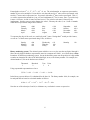
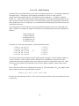
6
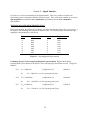
Another way of looking at a binary number in terms of its decimal value is as follows:
positional powers of 2:
decimal positional value:
binary number:
sum of decimal values
of "on" binary positions is:
25
32
24
16
23
8
22
4
21
2
20
1
1
1
0
1
0
12
32 +
16 +
0 +
4 +
0 +
1 = 5310
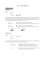
Figure 1.1 Values for Powers of 2.
210
29
28
27
26
25
24
23
22
21
20
1024
512
256
128
64
32
16
8
4
2
1
Binary to Decimal Conversion. The position of each digit represents the number 2 raised to an
exponent based on that position (starting at 20 for the rightmost digit). To convert to base 10, add all the
values where a one digit occurs. Ex:
1010112 =
1 x 25 + 0 x 24
+ 1 x 23
+ 0 x 22
+ 1 x 21
+ 1 x 20
=
32
+8
+2
+1
=
4310
Decimal to Binary Conversion. There are two methods that you can use to convert a decimal number to
a binary number. Both are explained below.
The Division Method. Divide by 2 until you reach zero, and then collect the remainders in reverse.
Ex 1:
2 ) 56 Rem:
2 ) 28
0
0
2 ) 14
2) 7
0
2) 3
1
2) 1
1
0
1
Answer:
5610 = 1110002
Ex 2:
2 ) 43 Rem:
2 ) 21 1
2 ) 10 1
2) 5 0
2) 2 1
2) 1 0
0 1
Ex 3:
2 ) 35 Rem:
2 ) 17 1
2) 8 1
2) 4 0
2) 2 0
2) 1 0
0 1
4310 = 1010112
3510 = 1000112
7
The Largest Fit Method. Subtract out largest power of 2 possible (without going below zero) each time
until you reach 0. Place a one in each position where you were able to subtract the value, and a 0 in each
position that you could not subtract out the value without going below zero.
Ex 1:
56
- 32
24
- 16
8
- 8
0
25
24
23
22
21
20
32
16
8
4
2
1
1
1
1
0
0
0
Answer: 5610 = 1110002
Ex 2:
35
- 32
3
- 2
1
-1
0
25
24
23
22
21
20
32
16
8
4
2
1
1
0
0
0
1
1
Answer: 3510 = 1000112
Ex 3:
21
- 16
5
- 4
1
-1
0
25
24
23
22
21
20
32
16
8
4
2
1
0
1
0
1
0
1
Answer: 2110 = 101012 (leading zeroes may be dropped)
8
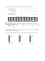
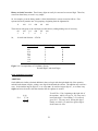
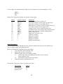
Character representation. To communicate with a computer using the everyday familiar symbols
requires a character code - a scheme for converting the letters, numbers, punctuation marks and other
symbols from the keyboard to the bits and bytes understood by the computer. The conversion must also
take place in the opposite direction - from the computer to the terminal screen or a printer. Each
character on the keyboard must have an equivalent code associated with it, that is made up of zeroes and
ones. The code must be agreed upon by all users of a specific computer. The two most widely used
codes have been ASCII and EBCDIC (used by IBM on its mainframe computers).
Today the code most widely used for this purpose is the American Standard Code for Information
Interchange (ASCII). The basic ASCII code is a fixed-length code which uses seven bits to represent
each character, thereby allowing 128 characters to be represented (27). An extended ASCII character set
using 8 bits allows 256 (28) characters to be represented. The extended set is used for such data
representation as graphics, foreign language symbols, and mathematical symbols. The first 32 ASCII
codes are non-printing control characters which can be used to control video displays, printers and
facilitate communications.
Rightmost
Four Bits
0000
0001
0010
0011
0100
0101
0110
0111
1000
1001
1010
1011
1100
1101
1110
1111
000
NUL
SOH
STX
ETX
EOT
ENQ
ACK
BEL
BS
HT
LF
VT
FF
CR
SO
SI
Leftmost Three Bits
010
011
Space
0
!
1
"
2
#
3
$
4
%
5
&
6
'
7
(
8
)
9
*
:
+
;
,
<
=
.
>
/
?
001
DLE
DC1
DC2
DC3
DC4
NAK
SYN
ETB
CAN
EM
SUB
ESC
FS
GS
RS
US
Figure 1.2
100
@
A
B
C
D
E
F
G
H
I
J
K
L
M
N
O
101
P
Q
R
S
T
U
V
W
X
Y
Z
[
\
]
^
_
110
`
a
b
c
d
e
f
g
h
i
j
k
l
m
n
o
111
p
q
r
s
t
u
v
w
x
y
z
{
|
}
~
DEL
The Basic ASCII Character Set.
NOTE: Codes less than 3210 or greater than 12610 on this chart are non-printable, however, they
generally appear as various symbols on output.
So, for example, to get the binary ASCII representation of the upper and lower case letters ‘f’ and ‘F’,
look up the leftmost three bits and rightmost four bits from the ASCII chart and put them together.
‘F’ = 100 0110
and
‘f’ = 110 0110
(binary ASCII values)
So the binary ASCII value for the letter ‘F’ is 1000110, and for the letter ‘f’ is 1100110.
9
These binary numbers can be converted to their decimal, octal, or hexadecimal value, as needed. For
example, since 10001102 is equivalent to 7010, it follows that: ‘F’ = 70 (decimal ASCII value).
Ex 2:
Find the binary ASCII and decimal ASCII values for the ‘%’ character.
From the chart:
‘%’ = 0100101
(binary ASCII value)
Convert the binary value to decimal:
01001012 = 32 + 4 + 1 = 3710
Therefore:
‘%’ = 37
Ex 3:
(decimal ASCII value)
Find the binary ASCII and octal ASCII values for the ‘#’ character.
From the chart:
‘#’ = 0100011
(binary ASCII value)
Group the bits by threes, starting at the rightmost of the seven bits, to convert to octal (add
leading zeros if necessary):
‘#’ = 100 011
Therefore:
‘#’ = 43
Ex 4:
=
43 (octal)
(octal ASCII value)
Find the hexadecimal ASCII and decimal ASCII values for the ‘f’ character.
From the chart:
‘f’ = 110 0110
(binary ASCII value)
Group the bits by fours, starting at the rightmost of the seven bits, to convert to hexadecimal (add
leading zeros if necessary):
‘f’ = 0110 0110
=
66 (hexadecimal ASCII value)
Convert either the binary or hexadecimal value to decimal to get the decimal ASCII value:
‘f’ = 66 (hex)
= (6 x 16) + (6 x 1)
10
=
102 (decimal ASCII value)
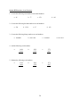
Section I Exercises (Binary Numbers and Code).
1. How many "states" can be represented by 6 binary circuits (positions)?
2. Convert the following binary numbers to decimal numbers:
a. 11110011
b. 1101101
c. 10000111
d. 101011
3. Convert the following decimal numbers to binary numbers:
a. 27
b. 133
c. 248
d. 91
4. What ASCII characters are represented by the following binary digits?
a. 0100000
b. 0111111
c. 1011010
d. 1110101
5. Convert the following phrase, character by character, to its binary, ASCII representation.
CS208 is fun!
6. What ASCII characters are represented by the following octal ASCII digits?
a. 115
b. 53
c. 175
7. What is the hexadecimal ASCII value for the following characters?
a. '&'
b. 'w'
c. 'A'
8. What is the decimal ASCII value for the following characters?
a. '&'
b. 't'
c. 'H'
11
Section I Exercise Answers.
1. How many "states" can be represented by 6 binary circuits (positions)?
ANS: 26 = 64
2. Convert the following binary numbers to decimal numbers:
ANS:
a. 11110011
243
b. 1101101
109
c. 10000111
135
d. 101011
43
3. Convert the following decimal numbers to binary numbers:
ANS:
a. 27
11011
b. 133
10000101
c. 248
11111000
d. 91
1011011
4. What ASCII characters are represented by the following binary digits?
ANS:
a. 0100000
‘Space’
b. 0111111
‘?’
c. 1011010
‘Z’
d. 1110101
‘u’
5. Convert the following phrase, character by character, to its binary, ASCII representation.
CS208 is fun!
ANS: 1000011 1010011 0110010 0110000 0111000
0100000
1101001 1110011
0100000
1100110 1110101 1101110 0100001
6.
(CS208)
(space)
(is)
(space)
(fun!)
What ASCII characters are represented by the following octal ASCII digits?
ANS:
a. 115
1001101
‘M’
b. 53
0101011
c. 175
1111101
‘+’
‘}’
7. What is the hexadecimal ASCII value for the following characters?
ANS:
a. '&'
0100110
26
b. 'w'
1110111
77
c. 'A'
1000001
41
8. What is the decimal ASCII value for the following characters?
ANS:
a. '&'
0100110
38
b. 't'
1110100
116
c. 'H'
1001000
72
12
Section II: Binary Operations
Arithmetic Operations.
ADDITION.
Rules.
0+0=0
0+1=1
1+0=1
1+1=0
1+1+1=1
with 1 to carry
with 1 to carry
Let’s explore the logic behind the addition rules, so they will make sense. 0+0, 0+1, and 1+0 produce the
same results as they would if you added them in the decimal number system, because the result is 1 or 0,
both of which can be represented with one digit in binary. But what happens when the result is more than
1, requiring more binary digits? Let’s look at the other two rules:
1 + 1 = 0,
with 1 to carry.
When you add 1+1 in decimal, you get decimal 2.
The equivalent of decimal 2 is binary 10, which means 0 with 1 to carry.
1 + 1 + 1 = 1,
with 1 to carry.
When you add 1+1+1 in decimal, you get decimal 3.
The equivalent of decimal 3 is binary 11, which means 1 with 1 to carry.
Ex 1:
1010 (10)
+0111 (7)
10001 (17)
Ex 2:
1001 (9)
+ 1011 (11)
10100 (20)
SUBTRACTION.
Rules.
0-0=0
0-1=1
1-0=1
1-1=0
102 - 1 = 1
with a borrow of 1
0-0, 1-1, and 1-0 again produce the same results as in decimal, because the result is 1 or 0, both of which
can be represented in binary. Now let’s analyze the other two rules:
0 - 1 = 1,
with 1 borrowed.
In decimal, the 1 that we borrow has a value of 10.
But in binary, the 1 that we borrow only has a value of 2. So
subtracting the original 1 from the borrowed 2 results in 1.
102 - 1 = 1,
The binary number 102 is equivalent to decimal value 2. So once
again, when we subtract 1 from 2, the result is 1.
13
Ex 1:
1001 (9)
-0101 (5)
0100 (4)
Ex 2:
0110 (6) Æ
-1111 (15)
1111 (15)
-0110 (6)
-1001 (-9)
To subtract a larger number from a smaller number: As with decimal arithmetic, the
smaller number is subtracted from the larger, and a minus sign is placed in front of the
result.
Logical Operations.
In addition to representing numbers, binary values may also represent other conditions. For example, a 1
may represent a value of true, while a 0 represents a value of false. Often entire bytes, or even several
bytes, are used in this manner. A particular bit, or set of bits, within the byte is set to 1 or 0 depending on
conditions encountered during the execution of a program. When so used, these bits are often called
"flags". Frequently, the programmer must manipulate these individual bits - an activity sometimes known
as "bit twiddling". The logical and shift operations provide the means for manipulating the bits.
OR, XOR, NOT and AND.
OR. Results in 1 if either or both of the operands are 1.
Rules.
0
0
1
1
OR
OR
OR
OR
0=0
1=1
0=1
1=1
Examples. To set or insure that a particular bit value is 1, OR the binary value with a string containing a
1 in the position you want set to 1, and zeros in the remaining positions to retain the original bit values.
Ex 1:
1001
OR 0010
1011
Ex 2:
0111
OR 0010
0111
In the previous examples, the OR operand works on the second value from the right, setting it to one,
while leaving the other values as they were. The target value is set to 1 regardless of its initial value.
XOR. The exclusive OR. Similar to OR except that it gives 0 when both its operands are 1.
Rules.
0
0
1
1
XOR
XOR
XOR
XOR
0=0
1=1
0=1
1=0
14
Examples. The XOR operation can be used to "flip" particular bits from 0 to 1 or from 1 to 0.
Ex 1:
1001
XOR 0010
1011
Ex 2:
0111
XOR 0010
0101
The first example above gives the same result as the first example for the OR operation. The second
example, unlike the previous second example, flips the 1 in the target position (second from right) to 0. If
XOR has an operand of 1111, it will flip all bits of a four bit value:
Ex 3:
1010
XOR 1111
0101
NOT. NOT is a separate operator for flipping all bits.
Rules.
NOT 0 = 1
NOT 1 = 0
Example.
NOT 1010
0101
AND. AND yields 1 only if both its operands are 1.
Rules.
0 AND 0 = 0
0 AND 1 = 0
1 AND 0 = 0
1 AND 1 = 1
Examples. AND can be used to set particular bits to 0. ANDing a four-bit value with 1001 sets the two
middle bits to zero and leaves the outer two bits unchanged.
Ex 1:
1101
AND 1001
1001
Ex 2:
0111
AND 1001
0001
Shift and Rotate Operations.
Whereas logical operations allow the changing of bit values in place, shift and rotate operations allow bits
to be moved left or right without changing their values.
SHL. SHL (shift left) shifts each bit one place to the left. The original leftmost bit is lost and a 0 is
shifted into the rightmost position.
Ex 1. SHL
1101
1010
Ex 2.
15
SHL
1100
1000
ROL. ROL (rotate left) shifts each bit one place to the left. The original leftmost bit is shifted into the
rightmost position. No bits are lost.
Ex 1. ROL
1101
1011
Ex 2.
ROL
1100
1001
SHR. SHR (shift right) shifts each bit one place to the right. The original rightmost bit is lost and a 0 is
shifted into the leftmost position.
Ex 1. SHR
1011
0101
Ex 2.
SHR
0011
0001
ROR. ROR (rotate right) shifts each bit one place to the right. The original rightmost bit is shifted into
the leftmost position. No bits are lost.
Ex 1. ROR
1011
1101
Ex 2.
ROR
0011
1001
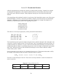
COMBINATIONS. A combination of logical and shift operations is often used to carry out bit
manipulations. For example, if we have two sets of four-bit values, 1011 and 0110, and want to isolate
the rightmost two bits of each and combine them into a single four-bit value, 1110, we could proceed as
follows:
1.
SHL
SHL
2.
1011
0110
0110
1100
AND
0110
0011
0010
OR
1100
0010
1110
3.
Our initial goal is to get the two rightmost bits of
1011 into the leftmost two positions, the position
these two bits will occupy in the final value. This
requires two SHL operations.
Now to isolate the rightmost bits of the second
value 0110, we AND the 0110 with the value
0011(which will set the left two bits to zero and
retain the value of the right two bits).
Finally, the two intermediate results, 1100 and
0010 can be OR’d to get the final desired result,
1110.
16
Section II Exercises (Binary Operations).
1. Add the following binary numbers:
a.
1001
+0010
b.
1101
+0110
c.
10010
+10110
d.
011100
+010111
2. Subtract the following binary numbers as indicated:
a. 1010
-0001
b. 11101
-00111
c. 110011
-100111
d. 0110011
-1111111
3. Show the results of the following binary logical operations:
a.
1111
AND 0000
d.
1001
XOR 1000
b.
1001
AND 0111
e.
c.
101010
OR 111100
NOT 0101
AND 1101
4. Show the results of the following shift operations:
a. SHL 0010
b. SHL 1111
c. SHR 0001
d. SHR 1111
c. ROR 0001
d. ROR 0111
5. Show the results of the following rotate operations:
a. ROL 0010
b. ROL 1110
17
Section II Exercises Answers.
1. Add the following binary numbers:
a. 1001 (9)
0010 (2)
1011 (11)
b. 1101 (13)
0110 ( 6)
10011 (19)
c. 10010 (18)
10110 (22)
101000 (40)
d. 011100 (28)
010111 (23)
110011 (51)
2. Subtract the following binary numbers as indicated:
a. 1010 (10)
-0001 ( 1)
1001 ( 9)
c. 110011 (51)
-100111 (39)
001100 (12)
b. 11101 (29)
-00111 ( 7)
10110 (22)
d. 0110011 ( 51) Æ
-1111111 (127)
1111111
-0110011
-1001100
Note for 2d. Since the subtrahend is larger than the minuend, the minuend is subtracted from the larger
subtrahend, and a minus sign appended to the result.
3. Show the results of the following binary logical operations:
a.
1111
AND 0000
ANS:
0000
e.
NOT 0101
AND 1101
ANS:
b.
1001
AND 0111
0001
Æ
c. 101010
OR 111100
111110
d.
1001
XOR 1000
0001
c. SHR 0001
0000
d. SHR 1111
0111
c. ROR 0001
1000
d. ROR 0111
1011
1010
AND 1101
1000
4. Show the results of the following shift operations:
ANS:
a. SHL 0010
0100
b. SHL 1111
1110
5. Show the results of the following rotate operations:
ANS:
a. ROL 0010
0100
b. ROL 1110
1101
18
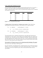
Section III: Octal Notation
No matter how convenient the binary system may be for digital computers, it is exceedingly cumbersome
for human beings. Consequently, most computer programmers use base 8 (octal) or base 16
(hexadecimal) representations instead. The computer system components --- assemblers, compilers,
loaders, etc -- convert these numbers to their binary equivalents. Octal and hexadecimal numbers are not
only convenient, but are also easily derived. Conversion simply requires the programmer to separate the
binary number into 3-bit or 4-bit groups. Let us examine the octal numbering system in this section, and
hexadecimal in the next.
Converting binary to octal is relatively easy because three binary digits equate to one of the eight octal
digits. Consider, for example, the sample set of machine level instructions presented at the beginning of
Section I:
1010111010110111
1110001110100011
0001010100111010
0111000101101110
0101010101110001
This same set of code may be grouped by 3, then presented in octal as:
1
1
0
0
0
010
110
001
111
101
111
001
010
000
010
010
110
100
101
101
110
100
111
101
110
111
011
010
110
001
127267
161643
012472
070556
052561
Æ
The octal system represents numbers using the eight symbols 0 through 7 (octal does not use digits 8 or
9), and is, therefore, a base-8 number system. Because the octal numbering system provides more
symbols than the binary numbering system, fewer digits are required to represent the same value. When
necessary to avoid confusion, the subscript 8 can be used to indicate a number written in this system:
22378
In the octal system, the base 8 is substituted for the base 10. The octal number 22378, for example, can be
analyzed and converted to a decimal number as follows:
12378 = 1 x 83 + 2 x 82 + 3 x 81 + 7 x 80 = 67110
Note the use of the subscripts 8 and 10. These can be used any time there is room for confusion in a term
or expression.
19
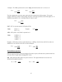
Another way of looking at an octal number in terms of its decimal value is as follows:
positional powers of 8:
80
decimal positional value:
1
octal number:
sum of decimal values
of the octal number
=
=
=
84
83
82
81
4096
512
64
8
1
3
5
6
28
1 x 4096 +
4096 +
600210
3 x 512 +
1536 +
5 x 64 +
320 +
6x8+
48
2x1
+2
So, as you can see, 135628 = 600210. Any octal number can be converted to its decimal equivalent using
this method.
Figure 3.1 Values for Powers of 8.
85
84
83
82
81
80
32768
4096
512
64
8
1
Octal to Decimal Conversion. The position of each digit represents the number 8 raised to an exponent
based on that position. To convert to base 10, beginning with the rightmost digit multiply each nth digit
by 16(n-1), and add all of the results together.
Ex:
251438 =
=
=
=
2 x 84
2 x 4096
8192
1085110
+ 5 x 83
+ 5 x 512
+ 2560
+ 1 x 82
+ 1 x 64
+ 64
+ 4 x 81
+4x8
+ 32
+ 3 x 80
+3x1
+3
Decimal to Octal Conversion. Divide by 8 until you reach zero, and then collect the remainders in
reverse.
Ex 1:
8 ) 176 Rem:
8 ) 22 0
8) 2 6
0
2
Answer:
17610 = 2608
Ex 2:
8 ) 2588
8 ) 323
8 ) 40
8)
5
0
Rem:
4
3
0
5
Answer:
258810 = 50348
20
Ex 3:
8 ) 5052 Rem:
8 ) 631
4
8 ) 78
7
8)
9
6
8)
1
1
0
1
Answer:
505210 = 116748
Binary to Octal Conversion. Three binary digits can easily be converted to one octal digit. Therefore,
conversion from binary to octal is very simple.
So, for example, given the binary number 11100111000101001, convert to octal as follows. First
separate the binary number into 3-bit groupings, beginning from the rightmost bit.
11
100
111
000
101
001
Then convert each group to an octal digit (see table below), adding leading zeros if necessary.
011
100
111
000
101
001
3
4
7
0
5
1
So,
111001110001010012 = 3470518
Three-bit Group
000
001
010
011
100
101
110
111
Decimal Digit
0
1
2
3
4
5
6
7
Octal Digit
0
1
2
3
4
5
6
7
Figure 3.2 Correspondence of 3-bit Binary Groups,
Decimal Digits, and Octal Digits.
Octal Arithmetic Operations.
ADDITION.
Octal addition is similar to decimal addition in that you begin with the right-hand side of the equation,
and add each column of digits, writing a one digit result beneath the column. The addition may result in a
carry. In decimal the largest digit is 9, so we carry tens. In octal, the largest digit is 7, so we must carry
eights, and write down the value that remains after the eight(s) are carried.
Ex 1.
(1)(1)
2 7 68
+ 3 5 48
6 5 28
To add 2768 + 3548 , beginning at the right side of
the equation: Add 6+4 to get 10. We carry one 8,
leaving the digit 2. Next adding 7+5+1(carried)
gives us 13. We carry one 8, leaving the digit 5.
Finally, we add 2+3+1(carried) to get the digit 6.
So the answer is 6528.
21
Figure 3.3 Octal Addition Table.
+
0
1
2
3
4
5
6
7
0
0
1
2
3
4
5
6
7
1
1
2
3
4
5
6
7
10
2
2
3
4
5
6
7
10
11
3
3
4
5
6
7
10
11
12
4
4
5
6
7
10
11
12
13
5
5
6
7
10
11
12
13
14
6
6
7
10
11
12
13
14
15
7
7
10
11
12
13
14
15
16
Note: When the result is a 2-digit number, it means carry one 8.
For example: 15 indicates a 5 digit with one 8 carried.
So when adding octal numbers, remember that you must carry one 8 whenever the sum of the digits adds
up to more than 7 (the biggest digit in octal). When the sum of the digits is equal or less than 7, simply
write the result.
(1) (1)
Ex 2.
6 1 78
+ 3 3 58
1 1 5 48
To add 6178 + 3358 , beginning at the right side of
the equation: Add 7+5 to get 12. We carry one 8,
leaving the digit 4. Next adding 3+1+1(carried)
gives us the digit 5. Finally, we add 6+3 to get 9.
We carry one 8, leaving the digit 1. The one carry
is written as the digit 1. So the answer is 11548.
SUBTRACTION.
Octal subtraction is similar to decimal subtraction in that you begin with the right-hand side of the
equation, and subtract each column of digits, writing a one digit result beneath the column. The
subtraction may require a borrow from the column to the left. In decimal we borrow one tens. In octal,
we borrow eights.
Ex 1.
6 7 28
- 3 5 48
3 1 68
We cannot subtract 4 from 2, so we must borrow
one. The one we borrow has a value of 8. Add the
borrowed 8 to the original 2 to get 10, and then
subtract the 4 (10-4), to get the digit 6. Since we
borrowed one, we now subtract 5 from 6 to get the
digit 1. Finally we subtract 3 from 6 to get the
leftmost 3 digit.
22
Figure 3.4 Octal Subtraction Table.
-
0
1
2
3
4
5
6
7
0
0
7b
6b
5b
4b
3b
2b
1b
1
1
0
7b
6b
5b
4b
3b
2b
2
2
1
0
7b
6b
5b
4b
3b
3
3
2
1
0
7b
6b
5b
4b
4
4
3
2
1
0
7b
6b
5b
5
5
4
3
2
1
0
7b
6b
6
6
5
4
3
2
1
0
7b
7
7
6
5
4
3
2
1
0
Note: bnotation means the result given is after borrowing one 8.
So when subtracting octal numbers, remember that when you borrow one, its value is 8.
Ex 2.
6 0 38
- 1 3 58
4 4 68
We cannot subtract 5 from 3, so we must borrow
one. We must go over two places to find one to
borrow. After borrowing from the 6, the middle
position now has a value of 8. We borrow one of
these 8s. Add the borrowed 8 to the original 3 to
get 11, and then subtract the 5 (11-5), to get the
digit 6. Now work on the middle digits. Subtract
the 3 from 7 (the one borrowed worth 8 minus the 1
lent) to get the digit 4. Finally, subtract 1 from the
remaining 5 (after lending one) to get the digit 4.
23
Section III Exercises (Octal Notation).
1. Convert the following octal numbers to decimal numbers:
a. 45
b. 77
c. 276
d. 143
2. Convert the following decimal numbers to octal numbers:
a. 234
b. 1234
c. 87
d. 103
3. Convert the following binary numbers to octal numbers:
a. 10100011
b. 00111110
c. 11001101
4. Add the following octal numbers.
a.
1624
+ 3434
b.
5632
+2331
c.
3771
+2617
5102
- 2335
c.
3171
- 2617
5. Subtract the following octal numbers.
a.
5324
- 3434
b.
24
d. 10111111
Section III Exercise Answers.
1. Convert the following octal numbers to decimal numbers:
ANS:
a. 45
37
b. 77
63
c. 276
190
d. 143
99
2. Convert the following decimal numbers to octal numbers:
ANS:
a. 234
352
b. 1234
2322
c. 87
127
d. 103
147
3. Convert the following binary numbers to octal numbers:
ANS:
a. 10100011
243
b. 00111110
76
c. 11001101
315
4. Add the following octal numbers.
a.
ANS:
1624
+ 3434
5260
b.
5632
+2331
10163
c.
3771
+2617
6610
5102
- 2335
2545
c.
3171
- 2617
352
5. Subtract the following octal numbers.
a.
ANS:
5324
- 3434
1670
b.
25
d. 10111111
277
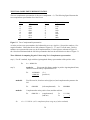
Section IV: Hexadecimal Notation
Often the programmer must examine the contents of certain memory locations. Normally, the contents
are displayed in hexadecimal (or hex) numbers rather than binary, because binary takes up too much
space and is more difficult to interpret. Many diagnostic messages are also output in hexadecimal
notation.
Converting binary to hexadecimal is relatively easy because four binary digits equate to one of the sixteen
hexadecimal digits. Therefore, each 8-bit byte within a computer can be converted to two hexadecimal
characters. And further, any bit stream can be converted. Consider, for example, the sample set of
machine level instructions presented at the beginning of Section I:
1010111010110111
1110001110100011
0001010100111010
0111000101101110
0101010101110001
This same set of code may be grouped by 4, then presented in hexadecimal as:
1010
1110
0001
0111
0101
1110
0011
0101
0001
0101
1011
1010
0011
0110
0111
0111
0011
1010
1110
0001
A
E
1
7
5
Î
E
3
5
1
5
B 7
A 3
3 A
6 E
7 1
The hexadecimal system represents numbers using the sixteen symbols 0 through 9 and A through F, and
is, therefore, a base-16 number system. We use the letters, since our numbering system only provides 10
symbols and letters are familiar to everyone. Because the hexadecimal numbering system provides more
symbols than either the binary or octal numbering systems, even fewer digits are required to represent the
same value. When necessary to avoid confusion, the subscript 16 can be used to indicate a number
written in this system: A1B716
In the hexadecimal system, the base 16 is substituted for the base 10. The hexadecimal number A1B716,
for example, can be analyzed and converted to a decimal number as follows:
A1B716 = 10 x 163 + 1 x 162 + 11 x 161 + 7 x 160 = 4139910
Note the use of the subscripts 16 and 10. These can be used any time there is room for confusion in a
term or expression.
Figure 4.1 Values of Powers of 16.
164
163
162
161
160
65536
4096
256
16
1
26
Another way of looking at a hexadecimal number in terms of its decimal value is as follows:
positional powers of 16:
decimal positional value:
hexadecimal number:
sum of decimal values of
the hexadecimal number=
=
=
163
4096
162
256
161
16
160
1
4
A
3
F
4 x 4096 +
16384 +
1900710
10 x 256 +
2560 +
3 x 16 +
48 +
15 x 1
15
So, as you can see, 4A3F16 = 1900710. Any hexadecimal number can be converted to its decimal
equivalent using this method.
Decimal to Hexadecimal Conversion. Divide by 16 until you reach zero, and collect the remainders in
reverse.
Ex 1:
16 ) 56
16 ) 3
0
Rem:
8
3
Answer:
5610 = 3816
Ex 2:
16 ) 2604
16 ) 162
16 ) 10
16 )
0
Rem:
12 Æ C
2
10 Æ A
Answer:
260410 = A2C16
Ex 3:
16 ) 5052
16 ) 315
16 ) 19
16 )
1
0
Rem:
12 Æ C
11 Æ B
3
1
Answer:
505210 = 13BC16
Binary to Hexadecimal Conversion. Four binary digits can easily be converted to one hexadecimal
digit. Therefore, conversion from binary to hexadecimal is very simple.
So, for example, given the binary number 11100111000101001, convert to hexadecimal as follows. First
separate the binary number into 4-bit groupings, beginning from the rightmost bit.
1
1100 1110 0010 1001
Then convert each group to an hexadecimal digit (see table below), adding leading zeros if necessary.
0001 1100 1110 0010 1001
1
C
E
2
9
So, 111001110001010012 = 1CE2916
27
Four-bit Group
0000
0001
0010
0011
0100
0101
0110
0111
1000
1001
1010
1011
1100
1101
1110
1111
Decimal Digit
0
1
2
3
4
5
6
7
8
9
10
11
12
13
14
15
Hexadecimal Digit
0
1
2
3
4
5
6
7
8
9
A
B
C
D
E
F
Figure 4.2 Correspondence of 4-bit Binary Groups,
Decimal Digits, and Hexadecimal Digits.
28
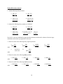
Hexadecimal Arithmetic Operations.
ADDITION.
Hexadecimal addition is similar to decimal addition in that you begin with the right-hand side of the
equation, and add each column of digits, writing a one digit result beneath the column. The addition may
result in a carry. In decimal the largest digit is 9, so we carry tens. In hexadecimal, the largest digit is F
(value=15), so we must carry sixteens, and write down the value that remains after the sixteen(s) are
carried.
Ex 1.
(1)(1)
A 7 616
+ 3 9 E16
E 1 416
(1)
Ex 2.
(1)
8 1 C16
+ B 9 516
1 3 B 116
To add A7616 + 39E16 , beginning at the right side
of the equation: Add 6+E to get the value 20. We
carry one 16, leaving the digit 4. Next adding
7+9+1(carried) gives us value 17. We carry one
16, leaving the digit 1. Finally, we add
A+3+1(carried) to get the value 14, which is
symbolized by the digit E. So the answer is E1416
To add 81C16 + B9516 , beginning at the right side
of the equation: Add C+5 to get value 17. We
carry one 16, leaving the digit 1. Next adding
9+1+1(carried) gives us the value 11, which is
symbolized by the digit B. Finally, we add 8+B to
get the value 19. We carry one 16, leaving the digit
3. The one carry is written as the digit 1. So the
answer is 13B116.
29
Figure 4.3 Hexadecimal Addition Table.
+
0
1
2
3
4
5
6
7
8
9
A
B
C
D
E
F
0
0
1
2
3
4
5
6
7
8
9
A
B
C
D
E
F
1
1
2
3
4
5
6
7
8
9
A
B
C
D
E
F
10
2
2
3
4
5
6
7
8
9
A
B
C
D
E
F
10
11
3
3
4
5
6
7
8
9
A
B
C
D
E
F
10
11
12
4
4
5
6
7
8
9
A
B
C
D
E
F
10
11
12
13
5
5
6
7
8
9
A
B
C
D
E
F
10
11
12
13
14
6
6
7
8
9
A
B
C
D
E
F
10
11
12
13
14
15
7
7
8
9
A
B
C
D
E
F
10
11
12
13
14
15
16
8
8
9
A
B
C
D
E
F
10
11
12
13
14
15
16
17
9
9
A
B
C
D
E
F
10
11
12
13
14
15
16
17
18
A
A
B
C
D
E
F
10
11
12
13
14
15
16
17
18
19
B
B
C
D
E
F
10
11
12
13
14
15
16
17
18
19
1A
C
C
D
E
F
10
11
12
13
14
15
16
17
18
19
1A
1B
D
D
E
F
10
11
12
13
14
15
16
17
18
19
1A
1B
1C
E
E
F
10
11
12
13
14
15
16
17
18
19
1A
1B
1C
1D
F
F
10
11
12
13
14
15
16
17
18
19
1A
1B
1C
1D
1E
Note: When the result is a 2-digit number, it means carry one 16.
For example: 1A indicates an A digit with one 16 carried.
So when adding hexadecimal numbers, remember that you must carry one 16 whenever the sum of the
digits adds up to more than E (value=15), the biggest digit in hex. When the sum of the digits is equal or
less than 15, simply write the result, remembering to use letters for values 10 to 15.
30
SUBTRACTION.
Hexadecimal subtraction is similar to decimal subtraction in that you begin with the right-hand side of the
equation, and subtract each column of digits, writing a one digit result beneath the column. The
subtraction may require a borrow from the column to the left. In decimal we borrow one tens. In octal,
we borrow sixteens.
Ex 1.
E 7 216
- 3 5 A16
B 1 816
Ex 2.
F 0 516
- 9 3 B16
5 C A16
To subtract E7216-35A16: We cannot subtract A
(value 10) from 2, so we must borrow one. The
one we borrow has a value of 16. Add the
borrowed 16 to the original 2 to get value 18.
Then subtract the A (18-A), to get the digit 8.
Since we borrowed one, we now subtract 5 from 6
to get the digit 1. Finally we subtract 3 from
E(value 14) to get the value 11, symbolized by the
leftmost B digit.
To subtract F0516-93B16: We cannot subtract B
(value 11) from 5, so we must borrow one. We
must go over two places to find one to borrow.
After borrowing from the F, the middle position
now has a value of 16. We borrow one of these
16s. Add the borrowed 16 to the original 5 to get
the value 21, and then subtract the B (21-11), to
get the value 10 symbolized by the digit A. Now
work on the middle digits. Subtract the 3 from 15
(the one borrowed worth 16 minus the 1 lent) to get
the value 12, symbolized by the digit C. Finally,
subtract 9 from the remaining 14 (after lending
one) to get the digit 5.
So remember, when subtracting hexadecimal numbers, when you borrow one, its value is 16.
31
Section IV Exercises (Hexadecimal Notation).
1. Convert the following hexadecimal numbers to decimal numbers:
a. 45
b. AC
c. F9B
d. 4C8
2. Convert the following decimal numbers to hexadecimal numbers:
a. 234
b. 1234
c. 87
d. 103
3. Convert the following binary numbers to hexadecimal numbers:
a. 10100011
b. 00111110
c. 11001101
4. Add the following hexadecimal numbers.
a.
823
+1 A B
b.
56E
+A28
c.
9B7
+92D
c.
AE93
- 5C4
5. Subtract the following hexadecimal numbers.
a.
D95
-B32
b.
B04
-83F
32
d. 10111111
Section IV Exercise Answers.
1. Convert the following hexadecimal numbers to decimal numbers:
ANS:
a. 45
69
b. AC
172
c. F9B
3995
d. 4C8
1224
2. Convert the following decimal numbers to hexadecimal numbers:
a. 234
ANS:
E A
b. 1234
4 D 2
c. 87
5 7
d. 103
6 7
3. Convert the following binary numbers to hexadecimal numbers:
ANS:
a. 10100011
A 3
b. 00111110
3 E
c. 11001101
C D
4. Add the following hexadecimal numbers.
a.
ANS:
823
+1 A B
9CE
b.
56E
+A28
F96
c.
9B7
+92D
12E4
c.
AE93
- 5C4
A8CF
5. Subtract the following hexadecimal numbers.
a.
ANS:
D95
-B32
263
b.
B04
-83F
2C5
33
d. 10111111
B F
Section V: Signed Numbers
Up till now we've been concentrating on unsigned numbers. There are a number of schemes for
representing positive and negative numbers in binary format. Three of the more common in use are the
sign-magnitude representation, one’s complement representation and the twos-complement
representation.
THE SIGN-MAGNITUDE REPRESENTATION.
In this representation, the leftmost bit of a binary code represents the sign of the value: 0 for positive, 1
for negative; the remaining bits represent the numeric value. The following figure illustrates the signmagnitude representation for a four-bit set.
Value
+0
+1
+2
+3
+4
+5
+6
+7
Representation
0000
0001
0010
0011
0100
0101
0110
0111
Value
-0
-1
-2
-3
-4
-5
-6
-7
Representation
1000
1001
1010
1011
1100
1101
1110
1111
Figure 5.1 Sign-Magnitude Representation.
Computing Negative Values using Sign/Magnitude representation. Begin with the binary
sign/magnitude representation of the positive value, and simply flip the leftmost zero bit. Using 8-bit
numbers:
Ex 1.
610 = 000001102
So:
Ex 2.
Ex 3.
(w/flipped bit) Æ
10100100
-3610 = 101001002 (in 8-bit sign/magnitude form)
7010 = 010001102
So:
10000110
-610 = 100001102 (in 8-bit sign/magnitude form)
3610 = 001001002
So:
(w/flipped bit) Æ
(w/flipped bit) Æ
-7010 = 110001102 (in 8-bit sign/magnitude form)
34
11000110
ONE’S COMPLEMENT REPRESENTATION.
In this representation, the leftmost bit of a binary code represents the sign of the value: 0 for positive, 1
for negative; For positive numbers, the remaining bits represent the numeric value. For negative
numbers, each bit of the numeric value is reversed. The following figure illustrates the one’s complement
representation for a four-bit set.
Value
+0
+1
+2
+3
+4
+5
+6
+7
Representation
0000
0001
0010
0011
0100
0101
0110
0111
Value
-0
-1
-2
-3
-4
-5
-6
-7
Representation
1111
1110
1101
1100
1011
1010
1001
1000
Figure 5.2 One’s Complement Representation
Computing Negative Values using One's Complement representation. Begin with the binary
sign/magnitude representation of the positive value, and flip every bit. Using 8-bit numbers:
Ex 1.
610 = 000001102
So:
Ex 2.
11111001
-610 = 111110012 (in 8-bit one’s complement form)
3610 = 001001002
So:
(w/all bits flipped) Æ
(w/all bits flipped) Æ
11011011
-3610 = 110110112 (in 8-bit one’s complement form)
The sign-magnitude and one’s complement representations are easily understood, but present some
disadvantages for use with computers. Before adding two sign-magnitude numbers, the computer must
examine their signs. If the signs are the same, the numbers are to be added; if they have opposite signs,
the smaller magnitude must be subtracted from the larger value. If the two numbers have the same sign,
that will be the sign of the result; if the signs are opposite, the sign of the larger number will be the sign
of the result. These operations slow the computer down.
These methods also differentiate between +0 and -0, a distinction not made in arithmetic. The computer
must convert the -0 to +0 whenever a negative 0 is encountered as the result of an arithmetic operation.
This is just one more disadvantage to slow things down.
Due to these drawbacks, sign-magnitude and one’s complement forms are rarely used for binary integers,
although, as we'll see later, sign-magnitude is often used for floating point numbers. For binary integers,
most computers use the twos-complement system, which avoids the problems found in the other
representations.
35
THE TWOS-COMPLEMENT REPRESENTATION.
The twos-complement representation is the (one’s complement + 1). The following figure illustrates the
twos-complement representation for a four-bit set:
Representation
0000
0001
0010
0011
0100
0101
0110
0111
Value
+0
+1
+2
+3
+4
+5
+6
+7
Value
-1
-2
-3
-4
-5
-6
-7
-8
Representation
1111
1110
1101
1100
1011
1010
1001
1000
Figure 5.3 Twos-Complement Representation
As in the previous two representations, the leftmost bit serves as a sign bit: 0 for positive numbers, 1 for
negative numbers. Notice that the two left columns of Figures 5.1, 5.2, and 5.3 are the same. Positive
numbers are represented the same way in all implementations. For the right two columns of Figure 5.3
the -0 has been eliminated and the four-bit representation has been inverted relative to those of Figure 5.1.
Three Methods of computing Negative Values using Two's Complement representation.
step 1) For all 3 methods, begin with the sign/magnitude binary representation of the positive value.
Ex.
step 2)
610 = 000001102
method a.
Given an n digit binary number in positive sign/magnitude form,
subtract it from the binary representation of 2n.
Ex.
method b.
00000110
(left complemented)
Æ
11111010
Complement the entire positive form, and then add one.
Ex.
So:
( 29 )
(positive 6)
Find first one bit, from low-order (right) end, and complement the pattern to the
left.
Ex.
method c.
100000000
- 00000110
11111010
00000110 ->
(complemented)
(add one)
Æ
Æ
11111001
+
1
11111010
-610 = 111110102 (in 2's complement form, using any of above methods)
36
Example 2:
step 1) For all 3 methods, begin with the sign/magnitude binary representation of the positive value.
7610 = 010011002
step 2)
method a.
Given an n digit binary number in positive sign/magnitude form,
subtract it from the binary representation of 2n.
Ex.
method b.
01001100
(left complemented)
Æ
10110100
Complement the entire positive form, and then add one.
Ex.
So:
( 29 )
(positive 76)
Find first one bit, from low-order (right) end, and complement the pattern to the
left.
Ex.
method c.
100000000
- 01001100
10110100
01001100 ->
(complemented)
(add one)
Æ
Æ
10110011
+
1
10110100
-7610 = 101101002 (in 2's complement form, using any of above methods)
The most important characteristic of the twos-complement system is that the binary codes can be added
and subtracted as if they were unsigned binary numbers, without regard to the signs of the numbers they
actually represent. Any carry from or borrow by the leftmost column is ignored. For example, to add +4
and -3, we simply add the corresponding binary codes, 0100 and 1101:
0100 (+4)
+1101 (-3)
0001 (+1)
A carry from the leftmost column has been ignored. The result, 0001, is the code for +1, the sum of +4
and -3. Likewise, to subtract +7 from +3, we subtract the code for +7, 0111, from that for +3, 0011:
0011 (+3)
-0111 (+7)
1100 (-4)
A borrow by the leftmost column has been ignored. The result, 1100, is the code for -4, the result of
subtracting +7 from +3.
37
Not only is addition and subtraction simplified in the twos-complement system, -0 has been eliminated,
replaced by -8, for which there is no corresponding positive number. In general, with n bits the twoscomplement system represents values ranging from -2n-1 through 2n-1 - 1; -2n-1 is the negative number
having no positive counterpart. Although this extra negative number can occasionally be troublesome, it
is not nearly so troublesome as -0 in the sign-magnitude and one’s complement representations.
The twos-complement system offers no particular advantages for multiplication and division. Many
computers convert twos-complement numbers to the sign-magnitude representation before multiplying or
dividing them, then convert the result back to twos-complement representation. Addition and subtraction,
however, are by far the most frequent operations performed on binary integers, so any system that speeds
up these operations is worthwhile even it makes multiplication and division more complicated.
38
Section V Exercises (Signed Numbers).
1. Convert the following decimal numbers to their 8-bit sign-magnitude representation:
a. 0
b. +3
c. -30
d. 25
2. Convert the following 8-bit sign-magnitude numbers to their decimal equivalents:
a. 10000011
b. 00000101
c. 00010001
d. 10100110
3. Convert the following decimal numbers to their 8-bit twos-complement representation:
a. 0
b. -6
c. +27
d. -38
4. Convert the following 8-bit twos-complement numbers to their decimal equivalents:
a. 11111110
b. 00000110
c. 11010110
d. 00101011
c. -17
d. -21
5. What is the 6-bit 2's complement value of:
a. -2
b. -10
6. Add or subtract the following twos-complementary numbers as indicated:
a. 0010
+0100
b. 1111
+1101
c. 110110
-000011
39
d. 101010
+010110
Section V Exercise Answers.
1. Convert the following decimal numbers to their 8-bit sign-magnitude representation:
ANS:
a. -0
10000000
b. +3
00000011
c. -20
10010100
d. 25
00011001
2. Convert the following 8-bit sign-magnitude numbers to their decimal equivalents:
a. 10000011
ANS:
-3
b. 00000101
+5
c. 00010001
+17
d. 10100110
-38
3. Convert the following decimal numbers to their 8-bit twos-complement representation:
ANS:
a. 0
00000000
b. -6
11111010
c. +27
00011011
d. -38
11011010
4. Convert the following 8-bit twos-complement numbers to their decimal equivalents:
ANS:
a. 11111110
-2
b. 00000110
+6
c. 11010110
-42
d. 00101011
+43
5. What is the 6-bit 2's complement value of:
a. -2
+2 =
1's comp:
ANS: -2 =
000010
111101
+1
111110
b. -10
c. -17
d. -21
+10 = 001010
110101
+1
-10 = 110110
+17 = 010001
101110
+1
-17 = 101111
+21 = 010101
101010
+1
-21 = 101011
6. Add or subtract the following twos-complement numbers as indicated:
a. 0010 (+2)
+0100 (+4)
0110 (+6)
b. 1111 (-1)
+ 1101 (-3)
1100 (-4)
c. 110110 (-10)
-000011 ( 3)
110011 (-13)
d. 101010 (-22)
+010110 (+22)
000000 ( 0)
NOTE: DIGITS CARRIED PAST THE LEFTMOST PLACE IN THE RESULTS ARE IGNORED.
40
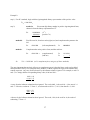
Section VI: Floating-Point Numbers
In the decimal system, a decimal point separates the whole numbers from the fractional part. Other
systems also use a point to separate these parts. Henceforth, this point will be known as a radix point,
since its use is not limited to the decimal numbering system.
In the decimal system, the digits to the right of the radix point, read from left to right, represent tenths,
hundredths, thousandths, and so forth. For example, 27.45 can be analyzed as:
Tens
2
Units
7
Tenths
4
Hundredths
5
Thus, 27.45 represents two tens, seven units, four tenths, and five hundredths. Arithmetically, this can be
expressed as:
27.45 = 2 x 10 + 7 x 1 + 4 x 1/10 + 5 x 1/100
We can represent the powers of ten in exponential notation by using the convention that a number with a
negative exponent is one over the number with the corresponding positive exponent - in symbols, a-n = =
1/an. Thus we can write 1/10 as 10-1 and 1/100 as 10-2:
27.45 = 2 x 101 + 7 x 100 + 4 x 10⁻¹ + 5 x 10⁻²
In binary notation, the digits to the right of the radix point, taken from left to right, represent halves,
quarters, eighths, and so on. For example, we can analyze 10.112 as:
Twos
1
Units
0
Halves
1
Quarters
1
Thus, 10.112 represents one two, zero units, one half, and one quarter. Arithmetically, we can express this
as:
10.112 = 1 x 2 + 0 x 1 + 1 x ½ + 1 x 1/4
= 2 + 0 + .5 + .25
= 2.75
Using exponential notation for the powers of two gives:
10.112 = 1 x 21 + 0 x 20 + 1 x 2-1 + 1 x 2-2
In the decimal system, numbers are often written in scientific or floating point notation. The significant
digits of a number are always written with the radix point between the first and second digits; this part of
the number is called the mantissa. The mantissa is multiplied by a power of 10 to move the radix point
to the desired position.
For example, 1,250,000 is written 1.25 x 10⁶. The mantissa is 1.25. Since multiplying a number by 10
moves the radix point one place to the right, multiplying by 106 - that is, multiplying by 10 six times,
moves the radix point six places to the right, giving 1,250,000.
41
In the same manner, 0.0000352 can be written in floating-point notation as 3.52 x 10⁻⁵. The mantissa is
3.52. Since multiplying a number by 1/10 moves the radix point one place to the left, multiplying by 10-5,
that is, multiplying by 1/10 five times, moves the radix point five places to the left, giving 0.0000352.
The advantage of floating-point notation is that nonsignificant zeros, zeros that serve only to show the
position of the radix point, do not have to be written. This is particularly important in computing, for we
usually have only a fixed number of digits with which to represent a number inside a computer. If some
of these digits are wasted on nonsignificant zeros, fewer digits are available to represent the significant
part of the number, and the accuracy with which the number can be represented is reduced.
Binary numbers can also be written in floating point in much the same manner as decimal numbers,
except that powers of two, rather than powers of ten are used to shift the radix point. For example,
11010000 can be written as 1.1012 x 27 and 0.0000111 as 1.112 x 2-5. For ease of reading, the exponents
(7 and -5) are written in decimal notation, although they must be coded in binary before being stored in
the computer.
IEEE Floating Point Representation.
Floating point numbers can be represented by binary codes by dividing them into three parts: the sign,
the exponent, and the mantissa. The sign-magnitude representation is often used to represent floating
point numbers since there is so much work involved with this type of number that the additional work
occasioned by the use of sign-magnitude is almost negligible.
The first, or leftmost, field of our floating point representation will be the sign bit: 0 for a positive
number, 1 for a negative number.
The second field of the floating point number will be the exponent. Since we must be able to represent
both positive and negative exponents, we will use a convention which uses a value known as a bias to
determine the representation of the exponent. For example, if we choose a bias of 127, we add 127 to the
value of the exponent before storing it. An exponent of 5 is therefore stored as 127 + 5 or 132; an
exponent of -5 is stored as 127 + (-5) OR 122. If the actual exponent ranges from -127 through 128, the
biased exponent, the value actually stored, will range from 0 through 255. This is the range of values
that can be represented by 8-bit, unsigned binary numbers. Thus we will store biased exponents as
unsigned binary numbers in an 8-bit field.
The mantissa is said to be normalized when the digit to the left of the radix point is 1. Every mantissa,
except the one corresponding to the number zero, can be normalized by choosing the exponent so that
the radix point falls to the right of the leftmost 1 bit. Ignoring zero for the moment, we will assume that
every mantissa is normalized. Since the digit to the left of the radix point is 1, we don't actually have to
store it; only bits to the right of the radix point need be stored. The mantissa is often stored in a 23 bit
field, which will be the size used in our examples (the total number of bits used for the three parts of our
floating-point representation is, therefore, 32, or four 8-bit bytes).
NOTE: As a special case, if all 32 bits in our floating-point representation are zeros, then the number
represents 0 (zero cannot be normalized and so the special case is necessary). Had we not defined zero as
a special case, the exponent, 00000000, would translate to 2-127.
42
Converting decimal floating point values to stored IEEE standard values.
Step 1. Compute the binary equivalent of the whole part and the fractional part.
Example 1: Given decimal value 40.15625, convert 40 and .15625.
40
- 32
8
- 8
0
Result:
101000
.15625
- .12500
.03125
- .03125
.0
Result:
.00101
So: 40.1562510 = 101000.001012
Step 2. Normalize the number by moving the decimal point to the right of the leftmost one.
101000.00101 = 1.0100000101 x 25
Step 3. Convert the exponent to a biased exponent
127 + 5 = 132 ==> 13210 = 100001002
Step 4. Store the results from above
Sign Exponent (from step 3) Significand (numbers to right of decimal from step 2)
0
10000100
01000001 01000000 0000000
Let’s try a second number:
Step 1. Compute the binary equivalent of the whole part and the fractional part.
Example 2: Given decimal value -24.75, convert 24 and .75.
24
- 16
8
- 8
0
Result:
11000
.75
- .50
.25
- .25
.0
Result:
.11
So: -24.7510 = -11000.112
Step 2. Normalize the number by moving the decimal point to the right of the leftmost one.
-11000.11 = -1.100011 x 24
Step 3. Convert the exponent to a biased exponent
127 + 4 = 131 ==> 13110 = 100000112
Step 4. Store the results from above
Sign Exponent (from step 3) Significand (numbers to right of decimal from step 2)
1
10000011
10001100 00000000 0000000
43
Sometimes the numbers are already in binary exponential notation, and just need to be converted to the
storage format. Now let's store the following number:
1.1012 x 27
The sign bit is 0, the biased exponent is 7 + 127 = 134 = 100001102. The bits to the right of the radix
point in the mantissa are 101 followed by enough 0s to fill out the 23-bit mantissa field:
Sign
0
Biased Exponent
10000110
Mantissa
10100000000000000000000
As another example, -1.112 x 2-5 is represented as:
Sign
1
Biased Exponent
01111010
Mantissa
11000000000000000000000
Converting stored IEEE standard values back to decimal floating point values.
To convert back to decimal, simply reverse the process.
Example: Given
Sign
0
Biased Exponent
10000010
Mantissa
10100110000000000000000
Step 1: Determine what the exponent value is by converting the biased exponent to an unbiased
value:
1000 0010 = 130
130 - 127 = 3
so the exponent is 3.
Step 2: Write the number in exponential notation, remembering to insert a 1 before the decimal
point, and placing the mantissa after the decimal point:
1.1010011 x 23
Step 3: Re-write the number in floating point format, without the exponent by moving the
decimal point the number of places indicated by the exponent.
1101.0011
Step 4: Convert the binary values to decimal.
1101 =
.0011 =
So the decimal equivalent is:
8+4+1=
13
.125 + .0625 = .1875
13.875
44
Section VI Exercises (Floating-Point Numbers).
1. Convert the following binary numbers to normalized exponential notation:
a. 11011
b. 101.111
c. 0.0011
d. 1.0011
2. Using a bias of 127 decimal, place the following exponents (expressed in decimal) in an 8 bit field
which represents the exponent in binary format.
a. 3
b. -8
c. 10
d. -2
3. Convert the following binary exponents, represented with a bias of 127, to their decimal equivalents.
a. 10000100
b. 01110011
c. 10001101
d. 01111001
4. Convert the following decimal floating point numbers to their 32 bit binary representation in the
sign/exponent/mantissa format; use a bias of 127 for the exponent:
a. 37.75
b. -25.125
c. 108.5
5. Convert the following 32 bit binary numbers to their decimal floating point equivalents. Assume a
bias of 127 for the exponent. Decimal answers may be rounded to two decimal points (0..0 indicates the
remainder of the mantissa is filled with zeros):
Sign
Exponent
Mantissa
a.
1
01111101
01000000000000000000000
b.
0
10000011
11010000000000000000000
c.
0
10000110
11010111110000000000000
45
Section VI Exercise Answers.
1. Convert the following binary numbers to normalized exponential notation:
a. 11011
ANS: 1.1011 x 24
b. 101.111
1.01111 x 22
c. 0.0011
1.1 x 2-3
d. 1.0011
1.0011 x 20
2. Using a bias of 127 decimal, place the following exponents (expressed in decimal) in an 8 bit field
which represents the exponent in binary format.
ANS:
a. 3
b. -8
c. 10
d. -2
INTERIM STEP:
3
+127
130
Add the bias (127) to each exponent:
-8
10
+127
+127
119
137
-2
+127
125
10000010
01110111
01111101
10001001
3. Convert the following binary exponents, represented with a bias of 127, to their decimal equivalents.
a. 10000100
ANS:
b. 01110011
c. 10001101
d. 01111001
INTERIM STEP - Convert the exponent to decimal and subtract the bias (127).
132
115
141
121
-127
-127
-127
-127
+5
-12
+14
-6
4. Convert the following decimal numbers to their 32 bit binary representation in the
sign/exponent/mantissa format; use a bias of 127 for the exponent:
a. 37.7510
Æ 100101.112 Æ 1.00101112 x 25
Æ
Sign Exponent
Mantissa
0
10000100
00101110..0
b. -25.12510
Æ -11001.0012 Æ -1.10010012 x 24
Æ
Sign Exponent
Mantissa
1
10000011
10010010..0
c. 108.510
Æ 1101100.12 Æ 1.10110012 x 26
Æ
Sign Exponent
Mantissa
0
10000101
10110010..0
ANS:
ANS:
ANS:
46
5. Convert the following 32 bit binary numbers to their decimal floating point equivalents. Assume a
bias of 127 for the exponent. Decimal answers may be rounded to two decimal points (0..0 indicates the
remainder of the mantissa is filled with zeros):
Sign
1
Exponent
01111101
Mantissa
010..0
INTERIM:
-
125-127=-2
-1.01 x 2-2
ANS:
-0.01012
a.
Æ -0.25 + 0.0625
Æ -0.3125 10
Sign
0
Exponent
10000011
Mantissa
11010..0
INTERIM:
+
131 – 127 = 4
1.1101 x 24
ANS:
111012 Æ 29.010
b.
c.
INTERIM:
Sign
0
Exponent
10000110
Mantissa
11010111110000000000000
+
134 – 127 = 7
1.1101011111 x 27
11101011 =
.111 =
ANS:
128 + 64 + 32 + 8 + 2 + 1 =
0.5 + 0.25 + 0.125 =
11101011.1112 =
235.87510
47
235
0.875
CHAPTER TWO
BASIC COMPUTER ARCHITECTURE
AND
SOFTWARE
48
Section I: A Simple Computer Model
We will use a simple computer model to study basic computer architecture and assembly language. Our
computer will consist of a keyboard for data input, a monitor for displaying output, random access
memory (RAM) to hold executing programs and data, a hard drive or floppy disk for program storage,
and a central processing unit.
Figure 1.1 The Computer Model
Í
Monitor (Output)
Î
Keyboard (Input)
ÍÎ
Disk (Storage)
Random Access Memory (32 RAM addresses)
0
1
2
3
4
5
6
7
8
9
10
11
12
13
14
15
16
17
18
19
20
21
22
23
24
25
26
27
28
29
30
31
^
|
|
v
Central Processing Unit (CPU)
includes Control Unit, ALU, and Registers
Random Access Memory (RAM)
Our computer's memory will consist of blocks of bits called words. Word sizes vary from computer to
computer. The word size for our simple computer will be 16 bits (two 8-bit bytes). Each word will hold
either data or program instructions. For simplicity, our model will work only with signed number data
(leftmost bit is the sign bit). To avoid consideration of -0, we will assume the use of the twoscomplement representation (range -32768 through 32767).
Figure 1.2 Representing Data with a 16-Bit Word
Sign
Number
15
14
0
Each word in our computer's memory is an addressable unit. Our model's memory (RAM) will consist of
32 addressable memory locations where data and instructions can be stored and retrieved as needed
during program execution. Data is stored in the computer as shown above in figure 1.2. Now we need a
method of storing instructions. There are 16 operations possible in our model computer's assembly
programming language. To represent 16 states, we need four bits. Therefore, the first 4 bits of any
instruction will be reserved for the operation code (opcode). The remaining bits will be used to refer to
any one of our 32 memory addresses, numbered 0 to 31.
49
Figure 1.3 Representing Instructions with a 16-Bit Word
OpCode
RAM Address
15
12
11
0
The central processing unit (CPU).
The CPU contains a small number of word-size memory locations called registers. Different registers
perform different tasks such as manipulating data, keeping track of the results of decision making
operations, and pointing to the next instruction to be executed.
Figure 1.4 The Five Registers of the CPU
Register A
Holds one operand
Register B
Holds 2nd operand and results
Instruction Register (IR)
Holds current instruction
Status Register
Holds status of last comparison
Program Counter (PC)
Holds address of next instruction
15
0
The program can load data from RAM into registers A and B for mathematical manipulation or logical
comparison. The other registers are used by the CPU to control program flow. The Instruction Register
(IR) contains the actual instruction which is currently being executed by the CPU. The Status Register
records the result of comparing the contents of register A with the contents of register B. The Program
Counter (PC) contains the address of the next instruction to be executed by the program.
Registers A & B hold the operands for each arithmetic operation (ie. the values on which the operation
will be performed). Arithmetic operations available are addition, subtraction, multiplication, and
division. After the operation has been carried out, the result is always stored in Register B. Therefore,
after an arithmetic operation has been performed, the second operand is no longer stored in Register B,
because it has been overwritten by the result of the operation.
The computer also has a Compare instruction that can be used to compare the contents of register A with
those of register B. The comparison can have three possible outcomes: (1) the contents of register A can
be less than those of register B; (2) the contents of the register A can be equal to those of register B; (3)
the contents of the register A can be greater than those of register B.
50
After a comparison has been done, the Status Register will hold a code that stores the results of the
comparison. The results are coded as follows:
-1
if the contents of register A are less than those of register B (A < B);
0
if the contents of registers A and B are the same (A = B);
1
if the contents of register A are greater than those of register B (A > B).
The Program Counter contains the address of the next instruction the computer is to execute. When a
program is loaded into RAM, the Program Counter is set to 0, so that the program will begin by running
the instruction at address 0.
Each instruction is run in two steps, known as the fetch-decode-execute cycle. During the fetch part of
the cycle the CPU fetches the next instruction from the address contained in the Program Counter and
places it in the Instruction Register.
As soon as an instruction is fetched, the CPU adds 1 to the contents of the Program Counter. Therefore,
consecutive instructions will normally come from consecutive memory locations (for sequential
programs). However, certain instructions called jump instructions can change the contents of the
Program Counter to new value, thus causing the computer to jump to some other part of the program and
continue execution from there. Jump instructions will be used for decisions and loops.
Once an instruction has been placed in the instruction register, a decode unit within the CPU deciphers
the instruction so that execution may begin. After execution of the instruction has been completed the
cycle starts all over again (unless the action of the instruction terminates the program).
51
Section II: A Model Assembly Language Instruction Set
A computer performs various tasks by executing a sequence of instructions that the processor is able to
understand. When a processor chip is designed, it is designed to understand and execute a set of machine
code instructions (OpCodes) unique to that chip. One step up from machine code is assembly code. Each
machine code instruction is given a mnemonic (name), so that it is easier for human beings to write code.
There is a one-to-one correspondence between the assembly languages mnemonic instructions and the
machine language numeric instructions. A list of assembly code instructions that will perform a task is
called an assembly program.
Assembly language is a language that allows total control over every individual machine instruction
generated by the assembler. High-level language compilers, on the other hand, make many decisions
about how a given language statement will be translated into machine instructions. For example, the
following single C++ instruction assigns a value of 55 to a numeric variable called Num:
Num = 55;
When the C++ compiler reads this line, it outputs a series of four or five machineinstructions that take the
value 55 and store it in memory at a location named Num. Normally, you the programmer have no idea
what these four or five instructions actually are, and you have no way of changing them, even if you
know a sequence of machine instructions that is faster and more efficient than the sequence the compiler
uses. Assembly language gives you the choice of which machine instructions will be used.
Assembly Language Concepts
• Each individual instruction is very simple. A single instruction rarely does more than move a single
word from one storage area to another, compute a value, or compare the value contained in one storage
area to a value contained in another. So you can concentrate on the simple task that is being accomplished
by the instruction without worrying about the complexity of the entire program.
• A program requires many instructions to do anything useful. You can often write a useful program in a
high-level language (like C++) in five or six lines. But a functional assembly language program cannot be
implemented in fewer than about twenty lines, and anything demanding takes hundreds or thousands of
lines.
• The key to assembly language is understanding memory addresses. In high-level languages like C++,
the compiler takes care of where the data is located—you simply have to give the constant or variable
data a name, and call it by that name when you want to use it. But in assembly language, you must always
be aware of where things are in your computer's memory. All data will be accessed via memory
addresses.
52
Model Assembly Language
We will use an assembly language code that consists of 16 instructions. The instruction set is listed
below.
Operation
STP
LDA
LDB
STR
INP
PNT
JLT
JGT
JEQ
JMP
CMP
ADD
SUB
MUL
DIV
MOD
What it means to the CPU
Stop the program
Load register A with contents of a specified memory location
Load register B with contents of a specified memory location
Store register B contents to a specified memory location
Store data input by user to a specified memory location
Print the contents of a specified memory location to the screen
Jump if less than (Status register = -1) to a specified memory location
Jump if greater than (Status register = 1) to a specified memory location
Jump if equal (Status register = 0) to a specified memory location
Unconditional jump to a specified memory location
Compare register A to register B and set Status Register value
Add (register A + register B) and store sum in register B
Subtract (register A - register B) and store difference in register B
Multiply (register A * register B) and store product in register B
Divide for quotient (register A / register B) and store quotient in register B
Divide for remainder (register A / register B) and store remainder in register B
Notice that instructions LDA, LDB, STR, INP, PNT, JLT, JGT, JEQ, and JMP all require a "specified
memory address". The complete instruction actually consists of two parts: an opcode and an operand.
The opcode is one of the operations listed above and the operation is a memory address.
The load and store instructions. The load instructions load values (ie. copy the contents) from main
memory locations into registers A and B. There is one load instruction for register A, LDA, and one for
register B, LDB. The store instruction, STR, stores a value (ie. copies the contents) from the register B
into main memory location.
Examples
The instruction: LDA 20
loads the contents of memory location 20 into the register A. The contents of memory location
20 are not affected by the copying; its value remains the same.
The instruction: LDB 21
loads the contents of memory location 21 into the register B. The contents of memory location 21
are not affected by the copying; its value remains the same.
The instruction: STR 22
stores the contents of register B into memory location 22. The contents of register B are not
affected by the copying; its value remains the same.
53
The input and output instructions. The input instruction, INP, transfers data entered by the user at the
computer's single input device (the keyboard) to a main memory location. The output instruction, PNT,
displays the data contents of a main memory location on the computer's single output device (the monitor
screen).
The instruction: INP 23
reads one number entered at the keyboard and stores it in memory location 23.
The instruction: PRT 23
displays the number in memory location 23. The contents of location 23 remain unchanged.
The arithmetic instructions. The arithmetic instructions are ADD, SUB, MUL, DIV, and MOD. There
are two division instructions, DIV and MOD. DIV yields the integer quotient of a division, while MOD
yields the remainder. For each instruction, one of the numbers on which the operation is to be carried out
must be in register A; the other must be in register B. The result of the operation is always stored back
into register B. Since the operands must be stored in the registers, these operations do not require a
memory address.
For addition and multiplication, the contents of the registers A and B are added/multiplied (ie. register A
+ register B). For subtraction, the contents of register B are subtracted from the contents of register A (ie.
register A - register B). For division, the contents of register B are divided into the contents of register A
(ie. register A / register B).
The instruction: ADD
adds contents registers A and B. The sum is stored in the
register B.
The instruction: SUB
subtracts the contents of register B from the contents of register
A. The difference is stored in register B.
The instruction: MUL
multiplies the contents of registers A and B. The product is
stored in register B.
The instruction: DIV
divides the contents of register A by the contents of register B.
The whole quotient is stored in register B.
The instruction: MOD
divides the contents of register A by the contents of register B.
The remainder of the division is stored in register B.
The compare instruction. The compare instruction and the jump instructions work together to
implement selection and repetition. The compare instruction, CMP, compares the contents of the register
A with the contents of register B.
54
The instruction: CMP
compares the contents of register A with the contents of register B. It records in the Status
Register whether register A's contents are less than, equal to, or greater than Register B's
contents, according to the following chart:
-1
if the contents of register A are less than those of register B (A < B);
0
if the contents of registers A and B are the same (A = B);
1
if the contents of register A are greater than those of register B (A > B).
The jump instructions. The unconditional jump instruction, JMP, changes the value of the program
counter, by storing a new memory address into it. This causes the computer to take its next instruction
from the newly specified address. The computer jumps to the point in the program specified in the jump
instruction and continues execution from that point.
The instruction: JMP 15
causes the computer to jump to memory location 15 and continue program execution from there.
In the absence of further jump instructions, the computer will execute the instructions in locations
16, 17, 18, and so on.
JLT, JEQ, and JGT are conditional jump instructions. The jump only takes place if the contents of the
Status Register have a particular value. If the contents of the Status Register do not have the required
value, the jump does not take place and the computer continues execution of the program with the
instruction in memory following the one that holds the jump instruction.
JLT jumps only if the contents of the status register are -1 (indicating register A was less than register B);
JEQ jumps only if the contents are 0 (A was equal to B); JGT jumps only if the contents are 1 (A was
greater than B).
The instruction: JLT 11
causes the computer to jump to location 11 in the program only if the contents of the status
register are -1 (register A's contents were less than register B's contents when last compared). If
the comparison code register contains 0 or 1, the computer continues with the instruction in the
memory location following the one containing the jump instruction (no jump).
The instruction: JGT 12
causes the computer to jump to location 12 in the program only if the contents of the status
register are 1 (A was greater than B).
The instruction: JEQ 11
causes the computer to jump to location 11 in the program only if the contents of the status
register are 0 (A was equal to B).
If the condition for one of these jumps is true, then the address after the jump instruction is loaded into the
program counter, which causes the jump to a new instruction.
55
The stop instruction. The stop instruction, STP, causes the CPU to stop fetching and executing
instructions and go into standby mode. The address part of the instruction is ignored.
The instruction: STP
brings the program execution to a stop.
WRITING ASSEMBLY CODE PROGRAMS (on our Model Computer)
Creating Programs
You can use any text editor to create your programs, as long as it has the ability to save the data in ASCII
format. Each line in the file will contain either program code (instructions) or program data. When a
program is loaded, the first instruction will be placed at memory location 0, followed by the rest of the
instructions in consecutive memory locations (ie. 1, 2, 3, 4...). Program data will be placed in memory
locations directly following the program instructions.
Code Formatting Forms:
Opcode
Opcode
Operand
0
16
1
17
2
18
3
19
4
20
5
21
6
22
7
23
8
24
9
25
10
26
11
27
12
28
13
29
14
30
15
31
Operand
Formatting for program instructions:
Type the OpCode (ie. operation) in columns 1-3 (Note: must use UPPERCASE)
Column 4 must contain a space.
Type the operand (ie. memory address) for instructions that require one in columns 5-6.
56
To create program data values:
Data values will be placed on the lines immediately following the STP operation in your program.
Beginning in column 1 of each line, type the value you wish to store in that memory location.
The Model Assembler
You will be using a model computer assembler. The program is located on the lab computers, and you
are welcome to make a copy on a diskette for use on your home/work computers.
Running Programs
After starting the assembler, you can run assembly programs. Enter the name of the file containing the
source code at the filename prompt. The program will be loaded into memory, and displayed on the
screen. The program counter contains 0, the address of the first instruction, and all other registers are
empty.
You can now run the program in either NORMAL or STEP mode.
NORMAL mode - Press 'r' to run (execute) the entire program.
The program will run, starting with the instruction at address 0, and will continue to run
until termination, pausing only to get input from the user.
STEP mode - Press any key to execute ONE step at a time.
The program begins to run, starting with the instruction at address 0. Each line of your
program code will take three steps to complete. Each time you press a key, one step will
execute. The steps are as follows:
1)
Fetch the instruction stored at the RAM address specified in the program counter
and place it in the instruction register.
2)
Increment the program counter by 1 (to point to the next instruction address).
3)
Decode and execute the instruction.
The program display will show the user how the computer loads and performs the
instructions within the program, as well as showing a simulated monitor to display the
results of the program input/output.
57
SAMPLE PROGRAMS
Sample Program #1.
Our first sample program will get a number as input from the user, and output its square to the user. First
we need an English-like algorithm to describe the steps needed to solve our problem.
1. Input a number and store it in memory.
2. Compute the square by multiplying the number times itself.
3. Store the result in memory.
4. Output the results from memory.
Since our sample program will use two memory locations to store data, as follows:
What's Stored
Input Number
Squared Result
Memory Address
07
08
Step 1 of the algorithm inputs the number from the user and stores it in location 07.
INP 07
Step 2 computes the square of the number at location 07. First the number at location 07 is loaded into
both registers. Then the register values are multiplied together. The result ends up in register B.
LDA 07
LDB 07
MUL
Step 3 stores the result (currently in register B) into memory location 08.
STR 08
Step 4 displays the contents of memory location 08 to the screen and then terminates the program.
PNT 08
STP
Putting all the instructions together, the program is shown below.
Address
00
01
02
03
04
05
06
07
08
Memory Contents
INP 07
LDA 07
LDB 07
MUL
STR 08
PNT 08
STP
?
?
Explanation
Get input number from user and store at location 07
Load input number into register A
Load input number into register B
Multiply register A by register B, result in B
Store result from register B into location 08
Output result stored in location 08
Terminate execution
Storage for Input Number
Storage for Squared Result
58
Sample Program #2.
Our second sample program will get a number from the user, and determine if the number is evenly
divisible by 5. Output zero (false) if the number is NOT evenly divisible by 5 or one (true) if the number
IS evenly divisible.
Again, we first we need an English-like algorithm to describe the steps needed to solve our problem.
1. Input a number and store it.
2. Determine if the input number is evenly divisible by 5.
2.1 Divide the input number by 5 to get the remainder.
2.2 Compare the remainder to 0.
2.2.1 If remainder equals 0, the number IS evenly divisible.
2.2.2 If the remainder does not equal 0, the number NOT evenly
divisible.
3. Output the results
3.1 If evenly divisible, output 1.
3.2 If NOT evenly divisible, output 0.
This sample program will use four memory locations to store data.
What's Stored
Zero
One
Five
Input number
Address
11
12
13
14
Step 1 of the algorithm inputs the number from the user and stores it in location 14.
INP 14
Step 2 determines if the number is evenly divisible by 5. This is accomplished by loading the register A
with the input number (from location 14), loading register B with value 5 (from location 13), and
MODing the registers. Then the results of the MOD are compared with zero, by loading 0 into register A
(from location 11) and comparing it to the remainder of the MOD in register B.
LDA 14
LDB 13
MOD
LDA 11
CMP
Step 3 takes the comparison results and outputs the answer. First, if the comparison showed the MOD
result in register B was equal to 0 telling us the number is evenly divisible by 5, then the program jumps
to output 1 (from location 12). Otherwise, the number is NOT evenly divisible, and the program outputs
zero (from location 11).
JEQ 09
PNT 11
59
If 0 was output, the program must then jump to the stop statement, to prevent outputting of 1 also.
JMP 10
PNT 12
STP
Putting all the instructions together, the program is shown below.
Address
00
01
02
03
04
05
06
07
08
09
10
11
12
13
14
Memory Contents
INP 14
LDA 14
LDB 13
MOD
LDA 11
CMP
JEQ 09
PNT 11
JMP 10
PNT 12
STP
0
1
5
?
Explanation
Input number and store in location 14
Load value at location 14 into register A (input num)
Load value at location 13 into register B (5)
MOD register A value (input num) by register B value (5)
Load value at location 11 into register A (0)
Compare register A (0) to register B (mod result)
If condition code 0 (values equal), jump to instruction 09
Output value at location 11 number (input number)
Jump to instruction 10
Output value at location 12 (0)
Terminate execution
Storage for constant 0
Storage for constant 1
Storage for constant 5
Storage for input number
Sample Program #3.
Our third sample program will add up a series of positive numbers entered by the user, until the user
enters a negative number, then display the total.
Below is the English-like algorithm to solve the problem.
1.
Copy the value 0 into the Running Total.
2.
Input a value and store it in memory.
3.
While the Input Value is not a negative number:
3.1
Add the Input Value to the Running Total and store the sum back
into the Running Total.
3.2
Input another value and store it in memory.
4.
Output the contents of the Running Total.
The program will use three memory locations to store data:
What's Stored
Zero
User input value
Running Total
Address
13
14
15
60
Step 1 of the algorithm clears the Running Total by copying 0 into the Running Total. This is done by
loading 0 (from location ) into the register B and storing it into the Running Total (at location ).
LDB 13
STR 15
Step 2 gets the the first input value to be processed and stores it in location
INP 14
Steps 3.1 and 3.2 are to be repeated only so long as the Input Value is greater than or equal to zero.
Before executing these steps, the computer must compare the contents of the Input Value with 0. If the
contents of the Input Value are less than 0, the computer is to jump around steps 3.1 and 3.2 and go
directly to step 4. If the Input Value is greater than or equal to 0 the computer is to continue with steps
3.1 and 3.2.
The program loads the Input Value (from location 14) into the register A, and 0 (from location 13) into
register B, then compares the contents of the two registers.
LDA 14
LDB 13
CMP
If the Input Value in register A is less than 0 in register B, the computer should jump to step 4, the
instructions for which begin at memory location 11.
JLT 11
If the Input Value in register A was greater than or equal to 0 in register B, the JLT instruction has no
effect, and the computer goes on to the instructions for steps 3.1 and 3.2. Step 3.1 adds the Input Value
(at location 14) to the Running Total (at location 15) and stores the result back into the Running Total.
The Input Value has already been loaded into the register A; thus we must load the Total into register B
and use an ADD instruction to add the contents of the two registers.
LDB 15
ADD
The STR instruction stores the resulting sum in register B back into the Running Total (at location 15).
STR 15
61
Steps 3.1 and 3.2 are to be repeated while the contents of the Input Value are greater than or equal to zero.
This means that when step 3.2 has been executed, the computer must jump back to the beginning of step
3. Step 3 will check the new Input Value, jumping to step 4 if the Input Value is negative and continuing
with steps 3.1 and 3.2 otherwise. When steps 3.1 and 3.2 have been executed, the computer will again
jump back to the beginning of step 3, where the next Input Value will be checked, and so on. An
unconditional jump instruction causes the computer to jump back to the beginning of step 3.
JMP 02
Step 4 outputs the Running Total (at location 15) and terminates the program.
PNT 15
STP
Putting all the instructions together, the program is shown below.
Address
00
01
02
03
04
05
06
07
08
09
10
11
12
13
14
15
Contents
LDB 13
STR 15
INP 14
LDA 14
LDB 13
CMP
JLT 11
LDB 15
ADD
STR 15
JMP 02
PNT 15
STP
0
?
?
Explanation
Load 0 into Register B (from location 13)
Store 0 into Total (initialize location 15)
Read user Input Value (into location 14)
Load Input Value (from location 14) into register A
Load 0 (from location 13) into register B
Compare contents of register A (input value) and register B (0)
Jump out of loop if contents of A < contents of B
Load the Total into register B
Add register A contents (input value) to register B contents (total)
Store resulting sum (in register B) to location 15 (total)
Jump back to start of loop for next input
Output total (from location 15)
Terminate program execution
Storage for constant 0
Storage for Input Value
Storage for Total
Section III Exercises (Software).
Using the assembly language instruction set:
1. Write a program which multiplies two numbers obtained from the input device and sends the results to
the output device.
2. Write a program which obtains two numbers from the input device, and sends the larger of the two
numbers to the output device.
3. Write a program which obtains a single number from the input device, adds the numbers 1 through 5 to
the number, and sends the results to the output device.
NOTE: The answers to the exercises for Section II will be presented in class.
62
CHAPTER THREE
THE
SYSTEM DEVELOPMENT
LIFE CYCLE (SDLC)
63
What is a system?
A system is a group of related components designed to work together in order to accomplish specific
objectives. Today’s computer-based systems are very large and complex. To build them, teams of
analysts, designers, programmers, testers and users must all work together. In order to manage this huge
task, the system development life cycle (SDLC) methodology was created. It provides an outline of
tasks and deliverables needed to develop systems. The SDLC methodology tracks a project from an idea
through implementation and post-implementation analysis.
Phases in the System Development Life Cycle
1.
Preliminary Investigation – Confirm the need for the new system and establish its feasibility.
Create a high-level view of the system, including its purpose and goals.
2.
System Analysis – Analyze the needs of the end users, the organizational environment, and the
current systems being used. Refine the project goals into functional requirements for the
system
3.
System Design – Create detailed system specifications from a technical viewpoint.
4.
System Development – Program, develop, or purchase the system parts, and assemble and test
the entire system.
5.
System Implementation – Train personnel and put the system into place.
6.
System Operation and Maintenance – Physically run and maintain the system. Implement
updates as needed.
The planning stages, systems analysis and design, are the most important stages. Good planning will
help reduce errors and decrease the chance of missing deadlines or extending schedules. An undetected
design error will take 10 times longer to fix during the development stage than it would have taken to fix
had it been detected and corrected during the planning stages.
When following the SDCL, you may occasionally need to go back to prior steps when subsequent
analysis points out problems. Typically, the life cycle has a spiral shape rather than a linear one, with
repeated steps back to previous activities as requirements are refined and new information is collected.
Each phase of the SDLC has sub steps, which will be covered below.
64
Preliminary
Investigation
Approved Feasibility
study
Abort Project
Go to next phase
Problem
Specifications
Systems
Analysis
Design
Specifications
Systems Design
Begin
Building a
new system
Go to Previous phase
Systems
Development
Coded and
tested System
Systems
Implementation
System converted
Users trained
Systems
Maintenance
Operational System
Documentation completed
Phase 1: Preliminary Investigation
During the preliminary investigation phase, an organization will determine whether a problem exists and
come up with alternative solutions to the problem.
The organization will conduct a feasibility study to determine the possibility of either improving the
existing system or developing a new system. The feasibility study must address economic, operational,
and technical feasibility. A system is economically feasible if the organization can afford to build and
operate it. A system is operationally feasible if the organization can introduce and operate it within the
organization’s current environment. A system is technically feasible if it can be built with currently
available technology.
A cost/benefit analysis will be conducted to determine whether or not the benefits of the new system
would make the cost worthwhile. If a system is currently in place, the cost/benefit analysis will compare
leaving the current system in place, improving the current system, and developing a new system.
Otherwise, the new system will be compared to current manual methods.
65
Ideally, the preliminary investigation will include a review of the organization's strategic plan to ensure
that the new system will help the organization achieve its strategic objectives. Management may need to
approve concept ideas before any money is budgeted for the system development.
The final output of the preliminary investigation is a Feasibility Report. The Feasibility Report includes
the system analyst’s findings on the feasibility of changing to a new system. It will state the project
purpose and goals, and outline each alternative with its costs, benefits and feasibility. The system analyst
will document all research and opinions for later viewing, and make recommendations as to whether the
project should move forward.
Phase 2: System Analysis
During the system analysis phase, data will be collected and analyzed.
The first step is to conduct an in-depth analysis of the current system and assess the needs of the system
users. The current system can be computerized or manual. Data will be gathered by reviewing written
documents, interviewing current and proposed system users, and observing processes at work. The
information gathered will help determine what the new system needs to do.
The Team
Information system professionals must involve end users in the system analysis process to ensure that the
new system will function correctly and meets their needs and expectations. A project team should be
assembled, composed of representatives from the various departments. The team should include users,
system analysts, and programmers.
After analyzing the gathered data, the team will create data flow diagrams for the entire work process.
The team will then give clarity to the project by defining the requirements for the new system. The
requirements should be defined from the user’s point of view. The requirements may include definitions
of the data used by system, data-flow diagrams describing the path(s) data takes through system, and
layouts of video screens, forms and reports.
Documentation produced by this phase will be methods used and compilations of gathered data, and any
tools (diagrams, tables, etc) used to analyze the data. The final output of the system analysis phase will
be a Requirements Document. The requirements document will summarize how the current system
works, what its problems are, and list requirements for the new system with included recommendations.
The Requirements Document should be referred to throughout the rest of the system development process
to ensure the developing project aligns with user needs and requirements.
Phase 3: System Design
The system design phase uses specifications in the Requirements Document from the systems analysis
phase to design a model of the new system. IS professionals create the system design, but must review
their work with the users to ensure the design meets users' needs. The IS team must determine the
necessary specifications for the hardware, software, people, and data resources, and the procedures that
will satisfy the functional requirements of the proposed system.
66
The process begins with a review of the review the major system components and the list alternative
systems. The team first develops a Preliminary Design describing the general capabilities of the new
system.
Computer-Aided Software Engineering (CASE) tools can help developers with the Detailed Design,
which will describe how the proposed system will deliver general capabilities described in the preliminary
design.
The final outputs of the system design phase is are a Detailed Design, including System Specifications
for input and output, processing and system control, storage and backup, and networking (if necessary).
The documentation will include data flow diagrams, system flowcharts, input/output designs, a data
dictionary, etc, for the new system. The Detailed Design will serve as a blueprint for the system during
system development.
Phase 4: System Development
During system development, the system parts are developed and/or acquired to match the system design.
Then the system parts are assembled, and the entire system is tested.
The organization must determine whether the system software will be bought or coded. A pre-written
software package will usually be cheaper than developing in-house software. This option will only work
if software exists that will meet the new system’s needs. If there is no such existing software package, the
organization can create the program itself, following the software development life cycle. Even if the
organization purchases existing software, coding and debugging may be required for the interfaces that
link the purchased software to existing systems that must communicate with the new system.
The system development phase does not change if the decision is made to purchase an off-the-shelf
program rather than develop an in-house system. The coding and debugging process is replaced with a
process used to evaluate the potential purchased products and to actually purchase the software.
Once the software has been chosen, the hardware to run it must be selected. At this point you can use
existing hardware, upgrade the existing hardware, or purchase new hardware.
A Request for Proposal (RFP) is used to solicit information from companies when you have
general requirements, but no specific hardware in mind. Using the RFP requirements, the
companies will propose systems that may work for your project.
A Request for Quotation (RFQ) is used to solicit quotes from companies when you have a
specific type of hardware in mind and want to get the best price.
After the hardware and software have been acquired (or developed), testing must be completed for each
unit, each subsystem, and the entire system. Module or unit testing is used to test each individual part of
the system, while integration testing tests system as a whole. The system must be tested to evaluate its
actual functionality in relation to expected or intended functionality. The tests should simulate typical
expected system usage.
During system development, documentation is written for the users and operators of the new system. The
user’s manual will summarize the benefits of the new system and provide detailed instructions for usage.
The operator's manual will detail how to run and maintain the system.
67
Phase 5: System Implementation
During system implementation, personnel are trained on the new system, and the system is put into
operation.
For training, make classes, documentation and one-on-one sessions available to users. The users need to
be made comfortable with the new system, to gain their support. Note that adequate training is essential
for user acceptance of a new system.
Another issue to consider during this stage would be converting old data into the new data. If the
previous system was manual, all the data must be entered into the new system. If the data existed on
another computer system, it may need to be converted for compatibility with the new system.
System Implementation/Conversion
There are several popular methods that can be used to convert the old system to the new system. The
organization must decide whether to implement the new system by the crash, parallel, phased, or pilot
testing method.
1. Direct Implementation
Also known as crash implementation or plunge implementation. Users stop using the old system
one day and start using the new system the next day. This method is risky, but also the least
costly.
2. Parallel Implementation
Run the old and the new systems side by side until the new system is proven stable and reliable.
When using this method, you will have the old system to fall back on if the new one has
problems. Parallel implementation is safer, but has greater manpower costs, since two systems
are in operation at once.
3. Phased Implementation
Parts of the new system are phased in separately over time, using either parallel or direct
implementation for each new part.
4. Pilot Implementation
Only a few users (or users at one location) try out the entire system. Once they have proved that
the system runs correctly, the system is installed for other users (or users at other locations).
Once the new system has been implemented, the organization needs to perform a post-implementation
analysis of the new system. The analysis should evaluate whether the new system is meeting the original
goals.
Phase 6: System Operation and Maintenance
The system operation and maintenance phase is an on-going process that continues until the end of the
system’s life.
Maintenance includes:
68
-
Keeping the machinery running
Fixing bugs that were not discovered during development
Updating and upgrading the system to keep pace with new requirements
Periodic system evaluations should also be performed to assess the capabilities, capacities, and whether or
not the system is still adequate for the required tasks and objectives. The system should be flexible
enough to accommodate minor changes. Major changes may require the organization to develop a new
system, and begin the SDLC all over again.
Computer-Aided Software Engineering (CASE) Tools
CASE tools are software products designed to help automate development of information systems. The
goal of CASE tools is to decrease the human effort involved, while increasing the quality of software.
The tools allow elements of the system to be drawn, described, stored, and where appropriate, to be
automatically generated.
Using previous methods, only 35% of the time was spent on analysis and design and 65% of the time was
used on coding and testing. CASE tools allowed analysts to apply as much as 85% of the time in the
analysis and design stages of the development. This resulted in systems that more accurately met the
users’ requirements and allowed for more efficient and effective systems to be developed.
CASE tools can be divided into two main groups. Those that deal with the first three parts of the system
development life cycle (preliminary investigation, analysis, and design) are referred to as Front-End
CASE tools or Upper CASE tools. Those that deal mainly with the Implementation and Installation are
referred to as Back-End CASE tools or Lower CASE tools.
By using a set of CASE tools, information generated from one tool can be passed to other tools, which, in
turn, will use the information to complete its task, and then pass the new information back to the system
to be used by other tools. CASE tools include:
Diagramming Tools - help develop system model diagrams and other visual-presentation
materials.
Prototyping Tools - help create a limited working model of the new system. The goal is to
demonstrate characteristics of system and allow users hands-on access, so they can test its
usefulness. The biggest problem with prototyping is that the most critical parts of a system are
often hard to prototype.
69
Quality Management Tools – analyze models and prototypes for consistency and completeness.
Inquiry and Reporting Tools – Extracts information from the data repository.
Data Repository – the data repository stores all data, data descriptions and formats, along with
what the data means and how it is used. Using a data repository can enforce accuracy and
consistency of data in the system.
Data Sharing Tools – provide import and export of repository information to/from software tools
that cannot directly access the repository.
Code Generators - Convert detailed specifications to executable source code.
Testing Tools - generate data to test the new system
Configurations management tools – help keep track of software revisions and versions.
Documentation tools - help simplify ongoing documentation process
Project management tools - assist with project planning, scheduling and reporting, problem
tracking, and resource management
The architecture of a CASE tool set is based upon a repository. The repository is a database containing
descriptions of each uniquely identifiable element of the project. All changes and additions are reflected
in the repository.
Prototyping
Tools
Quality
Management
Tools
Reporting
Tools
Diagramming
Tools
Project
Management
Tools
Documentation
Tools
CASE
Repository
Configuration
Management
Tools
Code
Generators
Testing
Tools
CASE tools integrate analysis, design and programming tools. Used throughout the SDLC, CASE tools
provide the following advantages:
- Ensure consistency, completeness and conformance to standards
o Standardizes data terminology and usage
- Improve quality and precision
70
-
Increase efficiency and productivity
Reduce the number of tedious tasks that need to be performed
Encourage communication between developers and users
Encourage collaboration among developers
Make structured techniques practical
Speed up the system development process
Reduce the overall cost of developing systems
Create better documentation through automatic generation and use of templates
Reduce lifetime maintenance
The disadvantages of CASE tools are:
- There are no real standards for CASE tools
- There is a lack consistency and interoperability between vendors
- Most CASE tools are inflexible – they permit little latitude for individual preferences
o Note: this may also be an advantage
- Few companies offer a fully complete and mature set of CASE tools
- There will be a short-term productivity loss for the time it takes the designers learn to use a
particular set of CASE tools
Many companies offer CASE tools. Some of the more popular sets are Rational Rose, Oracle Designer,
Visible Analyst, Excelerator, SilverRun, and PowerBuilder. Choosing the right set of CASE tools is
extremely critical. The various tools that support specific development tasks must be interoperable so
that you are working within an integrated CASE environment. With a mature set of CASE tools, used
correctly, the productivity gain should more than outweigh the short-term productivity loss.
Why do systems fail?
Systems fail for a variety of reasons. Among them are:
-
Lack of communication between management, users, and the systems analysts
Continuation of a project that should have been cancelled
Failure of two or more portions of the new system to fit together properly
Politics
Lack of management support
Technological incompetence
Major changes in available technology in the middle of a project.
Lack of user training
71
CHAPTER FOUR
PROGRAM
DEVELOPMENT
72
Section I: Program Design Tools
High-level programming languages are well suited to introduce the frequently used concepts of top-down
design and structured programming. These concepts evolved in the early 1970s as a methodical
approach to solving problems with the use of computers in mind. These techniques further lend
themselves to formal documentation of the design and implementation of problem solutions. This section
will provide an overview of some of these techniques.
TOOLS USED IN SYSTEM DESIGN
a) Data Flow Diagrams (DFD)
Graphic representation of a system that shows data flows to, from,and within the system,
processing functions that change the data, and storage of the data.
Symbols used:
Process Step
Data Source or
Data Link
Data Flow
File
Example: An advisor is helping a student plan his/her schedule.
Input
Get Course
Schedule & Degree
Course
Schedule
Degree Plan
Student
Display
Create Schedule
73
b) Algorithms
General algorithm definition - Step-by-step instructions on how to do a task; reducing a
task to the process of following directions.
Example: Algorithm for making coffee
1. Go to cupboard
2. Open cupboard
3. Take out can of coffee and one filter
4. Close cupboard
5. Remove filter holder from coffeemaker
6. Place filter in holder
7. Open coffee can
8. Measure 7 tsps of coffee into filter
9. Close coffee can
10. Put filter holder back in coffeemaker
11. Take coffee pot to sink
12. Turn on cold water
13. Fill pot to top line
14. Turn off water
15. Take pot back to coffee maker
16. Pour water into coffee maker
17. Place pot on burner
18. Turn on coffee maker
Computer algorithm definition - a finite sequence of unambiguous, executable steps that
ultimately terminate if followed. (Note: Machines are capable of performing only algorithmic
tasks.)
The general algorithm for the specification of many computer problems is:
1. Read Input
2. Process Data
3. Display Output
The program designer must then expand on each of these steps.
74
c) Flowcharts
Graphical diagram showing in detail each step of the program and the exact sequence in
which it occurs.
Symbols used:
START/STOP
INPUT/OUTPUT
DECISIONS
PROCESSING
FLOW OF CONTROL
Example: Compute worker’s pay, if overtime (over 40) hours are paid at double time.
START
Read Hours Worked & Hourly Wage
Pay = Hours Worked * Hourly Wage
YES
Hours Worked > 40?
OT = (HoursWorked – 40) * Hourly Wage
NO
Pay = Pay + OT
Output Pay
STOP
75
d) Structure Charts
Structure charts are used to specify the high-level design of a computer program. A structure
chart for a programmer is similar to a blueprint for an architect. In the design stage, the chart
is drawn and used as a way for the client and the software designers to communicate. During
program coding (building), the chart is continually referred to as the master-plan. It is often
modified as programmers learn new details about the program. After a program has been
implemented, the structure chart is used to fix bugs and make changes (maintenance). The
chart is especially important in this stage, because often the original “architect” is long gone,
and a programmer new to the project must use the chart as a navigational tool into the often
huge set of source code files.
The first step in creating a structure is to place the name of the program in the root of an
upside-down tree which forms the structure chart. The next step is to conceptualize the main
sub-tasks that must be performed by the program to solve the problem. These sub-tasks are
placed in rectangular boxes below the root, and connecting lines are drawn from the root to
each sub-task. Next, the programmer focuses on each sub-task individually, and
conceptualizes how each can be broken down into even smaller tasks. Eventually, the
program is broken down to a point where the bottom tasks of the tree represent very simple
tasks that can be coded with just a few program statements.
Example: Computing a taxpayer’s taxes (simplified).
Tax Calculation
Compute Adjusted Gross
Compute Adjustments
Wages
Compute Deductions
Compute Income
Capital Gains
Compute Tax or Refund
Mortgage Interest
Medical
Interest/Dividends
These hierarchical diagrams show the overall process structure, the relationship between the
modules of program code, and the shared data. Each box on a structure chart is a module,
that will eventually become a compilable set of program code.
As a design tool, they aid the programmer in dividing and conquering a large software
problem, by recursively breaking a problem down into parts that are small enough to be
understood by a human brain. The process is called top-down design or functional
decomposition.
76
Data Shared by Modules within the Structure Chart
It is important to know what data will be shared among different modules. On a structure
chart, each shared piece of data is denoted as input data, output data, or input/output data.
Input data is data that the calling task sends to the subtask. It is shown on the chart with an
arrow pointing down towards (into) the subtask.
Output data is data whose value is set by the called subtask. It is shown on the chart with an
arrow pointing up from (out of) the subtask. One way to look at output data is that the
calling task sends a blank piece of paper to the called subtask, which puts something on the
paper and sends it back.
Input/Output data is a data value that is sent in to a subtask, accessed by the subtask,
modified by the subtask, and passed back out. It is shown on the chart with an arrow pointing
down towards (into) the subtask AND an arrow pointing up from (out of) the subtask. One
way to look at input/output data is that the calling task sends the called subtask a piece of
paper with a value on it, and the called subtask looks at the value on the paper, modifies it,
and sends it back.
By specifying each piece of data as input, output, or input/output, the designer clearly states
the effect of each task. Thus, just by analyzing the data and arrows on a structure chart, and
without delving into code, a programmer can begin to understand a large program.
77
Taking the general algorithm from the previous section:
1.
Read Input
2.
Process Data
3.
Display Output
The structure chart could be:
main
Data
Get_Input
Result
Data
Result
Process_Data
Display_Results
Each node in the chart represents a module. A module is a piece of code that performs a
specific task. The root node represents the main module of the program. Each connecting
line represents a subtask module. Any data that is passed into or out of the module is listed
next to an arrow.
A structure chart is a high-level design notation, and leaves some coding details unspecified.
Specifically, control structures for decisions (IF/THEN) and looping (WHILE/DO) are not
depicted in a structure chart; All the above structure chart denotes is that the main program
will contain calls to modules Get_Input, Process_Data, and Display_Results - it says
nothing about other program statements that might be used.
You use structure charts in your design by starting with the entire problem to solve -- this is
the top box of your structure chart. Break this problem into major subproblems, and write
down how you could solve the entire problem if you could solve the subproblems. Repeat this
process for each subproblem until you've reached problems that you can solve directly. The
resulting structure chart and notes is your structured design. Your design documentation
should include both structure charts and the pseudocode you wrote during the above
decomposition process.
Once the structure chart has been designed, it is used to drive the software implementation.
Branches (tasks) of the tree are assigned as modules to be programmed by various members
of the development team.
78
Example
Any problem can generally be broken down into two or more simpler problems, which, when
addressed individually, can generally be solved easier than attempting to solve the problem as
a whole. For example, the updating of a checkbook can be refined to obtaining transaction
data (input), using the input data to process the update (deposits and withdrawals with new
balance), and presenting the bank customer with a new balance which reflects the transaction
which just occurred.
Using the discussion of stepwise refinement for the update problem, a simple structure chart
could be as follows:
0
Update Checkbook
TransType
Amount
Get Transaction
1
TransType
Amount
NewBalance
NewBalance
Process Transaction
2
Provide Results
3
MODULE SPECIFICATIONS.
From the general outline of the structure chart it is possible to provide some details as to what
each of the smaller problems represented in the block of the structure chart represent. The
blocks pictured in the structure chart are frequently called modules. For example, the
following specifications could be written for the modules depicted in the chart:
Module 0: Update Checkbook.
Update the current account balance from an input transaction. Provide the
customer with the results of the process.
Module 1: Get Transaction.
Customer provides bank teller (or ATM) with the desired transaction. The
transaction may be either a deposit or a withdrawal.
Module 2: Process Transaction.
The desired transaction (deposit or withdrawal) is processed against the current
account balance producing a new balance.
Module 3: Provide Results.
Provide the customer with a document reflecting the result of the transaction.
79
Section II: Software Overview
Computers are frequently classified as general purpose or special purpose. General purpose computers
are intended to do many different types of tasks while special purpose computers perform single tasks,
such as controlling cameras, microwaves, and automobile engines. In order to perform a variety of jobs,
general purpose computers rely on different sets of computer instructions.
Software is a set of such instructions, called a program, which tells a computer what to do and when to
do it. Applications programs such as word processors, spreadsheets, and database management systems
are well known to many computer users. Other programs, written in a variety of computer
programming languages, allow users to tailor programs to meet specific needs. Still other programs,
called system software, perform tasks which interface with the computer in such a way as to allow the
applications programs to run on the computer. This section will specify a low level instruction set for our
hypothetical computer which will allow it to perform a number of simple operations similar in nature to
those performed by real instruction sets in what is called assembly language. The next section will
provide an introduction to Turbo Pascal, a programming language which is much easier to read and work
with than an assembly language. Before specifying the language for our hypothetical computer, let's look
briefly look at a hierarchy of levels of languages.
Machine language.
As we saw in an earlier section, the instructions a computer executes are stored in binary-coded form
(zeroes and ones). These binary codes are called machine code or machine language. The central
processor can only execute programs coded in machine language. A machine language programmer has
to know the operation code for each operation the computer can carry out. Since most computers have
hundreds of operation codes, programmers will make frequent use of reference manuals for these codes.
These programmers must also be familiar with the internal organization (architecture) of the computer,
such as the central processing unit and the layout of main memory, even though they are not directly
related to the problem to be solved. Changing parts of a program may also involve changing references to
memory locations and relocating the position of various instructions. Thousands of machine language
instructions may be necessary to carry out a machine language program. In general, it is extremely
tedious to write programs in machine language so mnemonic languages have been developed to make
programming easier.
Assembly language.
Assembly language allows us to use convenient abbreviations (called mnemonics) for machine language
operations and memory locations. Each assembly language is specific to a particular hardware
architechture, and can only be used on a machine of that architecture. Since the CPU can only understand
machine language, an assembly language program must be translated into machine code before it can be
executed. The program that tells the computer how to perform the translation is called an assembler.
This kind of program is known as a language processor. Language processors allow computer systems to
execute programs written in languages other than machine language through the translation process.
With some exceptions, the assembly-language programmer must still write a line of code for each
machine instruction, therefore, while writing the code may be easier than writing it in machine language,
the programming process can still be tedious, especially for long programs. The programmer must also
be familiar with the architecture of the CPU and main memory. Macro instructions or macros provide
some relief by combining a series of machine language instructions into a single instruction. Macros are
particularly helpful when well defined code segments are to be used repeatedly within an assembly
language program. They can be labeled and called as needed (in somewhat the same manner as a DOS
80
batch file). Even with macros, however, assembly language is still tedious and requires knowledge of the
internal workings of the computer.
Higher-level languages.
Higher level languages hide many of the details of computer operation and are often very "English-like"
in their syntax. Since procedures for solving problems are expressed differently for various user
communities (business, science, mathematics, education, etc.) a number of different programming
languages have been developed to suit diverse needs over the years. FORTRAN has been in use by the
science, engineering, and mathematics communities for over thirty years. COBOL has been used by the
business community for almost the same length of time. BASIC, made popular by the microcomputer,
and vice versa, is widely used in secondary education and personal computing and is even used in
business applications. Pascal, developed primarily as a language for teaching modular programming
techniques, has found uses in personal computing, business, and computer science research as well as
college-level education. C is a newer, general purpose language. It is sometimes called a “mid-level”
language, since it can be used to implement low-level functions that were previously written in assembly,
without giving up any features of an HOL. There are close to 200 various computer languages and
dialects currently in use (although the most frequently used number around 20).
Language processors.
As mentioned earlier, translator programs are used to convert non-machine language programs to machine
code. A translator program for assembly language is usually called an assembler; translators for higher
level languages are often called compilers. Translators, assemblers, and compilers are all examples of
language processors. The result of the translation process is always a machine language program that
can be executed by the computer just as if it had been coded by hand. The program to be translated is
called the source program and the program produced by the translator is called the object program.
In practice, an additional step called linking must often be taken before a translated program can be
executed. The object program produced by the translator may call (invoke) subprograms stored in
auxiliary memory. The object program often contains references to these subprograms but does not
contain the subprogram code. The linker is used to combine the object code with any subprogram code
(already in machine code format) to produce an executable program which the computer can run.
Interpreters are another widely used type of language processor. Instead of going, in order, through the
processes just described for the entire source program, the source program is executed by the interpreter
one instruction at a time. It can take much longer to execute an interpreted program than a translated one.
Most programs specify that some statements will be executed many times. Such repeated statements need
to be analyzed only once by a translator, but an interpreter must analyze a repeated statement each time it
is executed. An advantage of the interpreter is that it simplifies error correction and program
modification by allowing the programmer to execute the program a few lines at a time, detect and correct
errors, and run those same lines of code again without having to go through the entire translation process
each time. (Many language compilers mitigate this advantage by providing excellent "debug" and
correction facilities).
81
Section III: An Introduction to the C++ Language
INTRODUCTION
In general, high-level languages (HOLs) combine several assembly language instructions into a single
HOL statement to simplify the programming process. Addition in assembler requires the programmer to
write several instructions, which include moving data to and from memory to the accumulator, as well as
performing the addition. Arithmetic can be performed in one instruction in a HOL, as, for example:
x = y + z;
There are two principal reasons for high-level languages. The first is to make program development
easier – each instruction written in a HOL might represent dozens or hundreds of lower-level assembly
instructions. The second is to make programs portable. A standard program written for one computer can
be re-compiled and run on another.
C++ is one of these HOLs. C++ was developed by Bjarne Stroustrup of AT&T Bell Laboratories in the
early 1980s, and is based on the C language. C++ supports the problem solving techniques of top down
design and structured programming.
Characteristics of Structured Programming:
• Uses canonical control structures only (ie. have only a single entry/ exit)
•
Is subdivided into modules (one logical thought, approximately one page long)
•
Each page is organized into recognizable paragraphs, using indentation to show nesting and
subordinate clauses.
•
Embedded comments describe the function of each variable and purpose of each module.
•
Straightforward, easily readable code is preferred over slightly more efficient, but obtuse, code.
•
Final program is created via top-down design.
- First develop the main code with empty modules.
- Slowly refine to lowest level -- DEFER THE DETAILS.
- Keeps programmer from being overwhelmed by job, and allows easy division of work
(modules assigned to different programmers).
Benefits of Structured Programming:
1. More readable
2. Easier to maintain
3. More likely to be correct on first run
4. Easier to "prove" by systematic program verification
This chapter will examine C++, in sufficient detail to allow the student to write several short simple
programs. All of today's programming languages have their own environments for assisting the
programmer, whether the work is being accomplished for microcomputer, minicomputer, or mainframe
82
applications. Familiarity with one such environment brings a general understanding of what may be found
in the development environment of other languages (or different versions of the same language). It is
emphasized that the C++ language will be covered only to the extent necessary to explore its
accompanying environment.
In order to learn the basics of C++, we will learn about a subset of C++. Using just some of the
statements in C++, you can write many short C++ programs. We will concentrate on the following set of
statements:
Statement
#include <iostream.h>
void main()
const
int
double
cin
cout
assignment (=)
if-else
while
Meaning
to include supporting code libraries for input and output
to define the main function
to define constants
to define integers
to define floating point numbers
to read input
to write output
to perform calculations
to make decisions
to loop
A SIMPLE PROGRAM.
#include <iostream.h>
void main()
{
cout << "Danger!!";
}
The program simply displays the message "Danger!!" on the screen (without the quotes).
NOTES FOR THE SIMPLE PROGRAM.
All the bolded words have special meaning.
1.
The first line contains a compiler directive.
a. The include directive tells the program to use the iostream.h code library, which contains
code that supports input and output.
You will type this line at the top of every program you write for this class.
2.
Either upper or lower cases letters or a mixture of both may be used with C++ statements. But
you must remember that C++ is case-sensitive. Therefore, you must always type names exactly
as you define them.
3.
"{" and "}" are boundary scopes which indicate where blocks of code are to be found.
83
4.
The "cout" statement is used to provide output to the screen. Literal output is enclosed in double
quotes. Anything between the " " will be displayed exactly as is.
5.
Note the use of the semi-colon (;) in the program. Semi-colons are used to terminate declarations
and statements.
Using the C/C++ Compiler
Follow these steps:
1) Use the editor to create/edit C++ code in a text file
NOTE: C++ filenames ended with extension .cpp
2) Compile and link the C++ file
3) Execute the executable file created
4) If find bugs or errors, go back to the first step and correct them and try again.
If you execute your executable file with the code written exactly as shown in the previous example, the
DOS window may close before you have a chance to see your results. Therefore, you will have to add the
following lines to EVERY C++ program that you write.
At the TOP of the file, add:
#include <stdlib.h>
At the BOTTOM of the file, just BEFORE the closing brace '}', add:
cout << endl << endl;
system("PAUSE");
So, for example, the SIMPLE PROGRAM on the previous page would become:
#include <stdlib.h>
#include <iostream.h>
void main()
{
cout << "Danger!!";
cout << endl << endl;
system("PAUSE");
}
84
Program Structure:
<directives-section>
<function-header>
{
<declaration-section>
<executable-section>
}
The directives section tells the compiler which libraries to use.
The include directive tells the compiler and the linker to link the program to a code library.
The header file iostream contains routines that handle input from the keyboard and output to
the screen (specifically the cin and cout statements).
The function header begins and names a function. The reserved word main is used to define the main
function within a program. A C++ program will always begin execution with the function named main.
Therefore, your program MUST contain a function named main. In this course, we will use ONLY the
main function in our programs.
The declaration section defines program data. The programmer must determine in advance what data
the program will use, and how it will be stored. Each piece of data that will be used in the program must
be defined in the declaration section as either a constant or a variable. C++ requires that all constants and
variables used in a program be given a data type. Declaring a variable to be of a specific type signals the
compiler that it must reserve enough memory for the constant/variable to store that particular data value
as the program executes.
C++ has two built-in data types for storing numbers: int and double.
The int data type is used to store whole numbers. When typing these numbers, do not include
leading zeros, commas or any other non-digit characters, except a sign (+/-).
The double data type is used to store numbers written with a decimal point.
A third data type, char, is used to store one ASCII character, enclosed in single quotes.
A data item may be stored as a constant or a variable.
A constant’s value must be known before the program is run, and cannot be changed while the
program is running. Defining a constant reserves a space in memory and stores a value in it.
A variable’s value does not have to be determined until the program is running, and may change
as often as is necessary. Defining a variable reserves a space in memory, large enough to store
the type of data specified, and gives the memory location a name.
85
You must determine whether a piece of data should be a constant or a variable, and what data type (int,
double, char) it should be.
Variable declaration format
<type> <variable-name>;
Examples:
char Initial;
int Count;
double GPA;
Constant declaration format
const <type> <constant-name> = <value>;
Examples:
const
const
const
const
double Pi = 3.14;
double Taxrate = 0.28;
int MaxItems = 50;
char BestGrade = 'A';
Constant/variable names must begin with a letter, followed by any number of letters, digits, and
underscores. You should choose names for your constants and variables that are descriptive, so it is easy
to tell what will be stored in them.
The following is a list of reserved words that have a predefined meaning. They CANNOT be used as
constant or variable names:
asm
auto
break
case
catch
char
class
const
using
true
continue
default
delete
do
double
else
enum
extern
namespace
false
float
for
friend
goto
if
inline
int
long
bool
new
operator
private
protected
public
register
return
short
static_cast
86
signed
sizeof
static
struct
switch
template
this
throw
const_cast
try
typedef
union
unsigned
virtual
void
volatile
while
dynamic_cast
THE FUNCTION BODY
The function body includes all lines of code between "{" and "}". Each C++ statement will end with a
semicolon. You will learn about five different types of executable statements.
Assignment Statement (=)
Assigns a value to a previously defined variable. The variable name must appear on the left side of the
statement and the value on the right side of the statement. The variable and the value must be of the same
data type.
Æ store 5 in the variable Count memory location
Count = 5;
The following math operators may be used to compute values within assignment statements:
+
*
/
%
Add
Subtract
Multiply
Division
Modulus (Remainder)
Examples:
Average = (Num1 + Num2) / 2;
Square = Num1 * Num1;
Value = Value + 1;
NOTE: It is a good idea to put one space before and after any operator, for readability.
Input/Output Statements
Input statements get input from the user’s keyboard, and output statements display output to the user’s
monitor.
cout – writes output to the monitor
In general, the program statement
cout << Expression1 << Expression2 << ... << ExpressionN;
will produce the screen output
Expression1Expression2...ExpressionN
The series of statements
cout << Expression1;
cout << Expression2;
...
...
cout << ExpressionN;
will produce an identical output.
87
If you need a space between expressions, you must include them explicitly. Thus:
cout << Expression1 << " " << Expression2
produces
Expression1 Expression2
You can use either the expression endl to output a new line.The numbers in bold in the
example screen output above have been typed in by the user
cout Examples:
cin
cout << "Hello" << endl;
cout << "Please enter a number: ";
cout << "The answer is " << Sum;
- gets input from the keyboard (typed in by the user)
In general, the program statement
cin >> Variable-Name;
will store the data typed in by the user into the variable that is named.
Example:
cout << "Enter pay amount:";
cin >> Pay;
The cout statement prints a prompt on the display screen.
The cin statement stores the number typed in at keyboard into variable Pay.
88
A SLIGHTLY MORE COMPLEX PROGRAM.
#include <stdlib.h>
#include <iostream.h>
// Include directive (for PAUSE)
// Include directive (for Input/Output)
void main()
{
// main function header
// Start main function
const double Pi = 3.14159;
double Radius, Area;
// Declares constant value for the name Pi
// Declares two variables to store double values
cout << "Enter circle radius: ";
cin >> Radius;
// Prompts the user for keyboard input
Area =
// Calculates the area, using Radius and Pi
Pi * Radius * Radius;
// Reads number typed at keyboard
// into the memory location called Radius
cout << endl << endl;
cout << "Area = ";
cout << Area;
// Writes" one blank line to the screen
// Displays text “Area =”
// Displays value stored in variable Area
cout << endl << endl;
system("PAUSE");
// Display a blank line
// Pause before closing output window
// End of the function main
}
NOTES FOR PROGRAM.
1.
Constants and variables are declared at the top of the function. Constant values cannot change.
Variables are like named mail boxes where the contents constantly change as the program
executes.
2.
The "=" assignment operator places the value on its right side into the variable on the left side.
It is perfectly legal to have the same variable on both sides of the assignment operator. For
example, if x had an initial value of 10, then the expression x = x + 5 is the same as x = 10 + 5.
3.
"cin" is the means by which data is entered from the keyboard. The cin statement results in the
cursor blinking on the screen until you enter the appropriate type of data. It is a good idea to
always precede a cin statement with a cout statement, which prompts the user to enter a data.
That way, the user is not confronted with a blinking cursor on a blank screen and no idea of what
to enter.
4.
"//" The double slashes are used to place comments in the program. Comments are ignored by
the compiler and so are not executed.
89
Section IV: C++ Decisions
RELATIONAL OPERATORS
Two values can be compared in C++ using relational operators. Relational operators test the relationship
between two values and returns a TRUE or FALSE result.
Operator
==
!=
<
<=
>
>=
Example
A == B
A != B
A < B
A <= B
A > B
A >= B
Result
TRUE if A is equal to B
TRUE if A is not equal to B
TRUE if A is less than B
TRUE if A is less than or equal to B
TRUE if A is greater than B
TRUE if A is greater than or equal to B
The IF Statement
Is used to make decisions about what statements in a program should be executed.
One Alternative
– allows a single statement to be executed or skipped, based on the test condition.
if ( <condition> )
<statementT>;
{do statement if condition is TRUE}
Two Alternatives
– allows a choice between two alternative statements to be executed.
if ( <condition> )
<statementT>;
else
<statementF>;
{do if TRUE}
{do if FALSE}
Examples:
if (Age > 18)
cout << "Can Vote";
if (Divisor != 0)
Answer = Num / Divisor;
if (Num >= 0)
cout << "Positive number";
else
cout << "Negative number";
90
A DECISION PROGRAM, USING AN IF STATEMENT.
#include <stdlib.h>
#include <iostream.h>
// Include directives
void main()
{
const int Highest = 100;
int Num;
// main function header
// Start main function
// Stores value 100 into constant Highest
// Declares an integer type variable Num
cout << "Enter a Number up to 100: ";
cin >> Num;
cout << endl << endl;
if (Num <= Highest)
cout << "Input is okay";
else
cout << "Error - bad input!";
cout << endl << endl;
system("PAUSE");
// Prompts user for a number
// Reads user’s number into Num
//Display blank line
// Tests if Num less than or equal to Highest
// Do this statement if test is TRUE
// Do this statement if test is FALSE
// Pause before closing output window
// End of function
}
NOTES ON PROGRAM.
1.
The number entered by the user is stored in variable Num.
2.
Num is compared to the constant value 100, stored in the constant Highest.
3.
The decision about which statement to run is based on the evaluation of the variable Num.
When Num is less than or equal to Highest, the if statement evaluates to TRUE, and the
statement cout << "Input is okay"; is executed.
When Num is greater than Highest, the if statement evaluates to FALSE, and the
statement, cout << "Input is okay"; is executed.
4.
You should always use meaningful names for your constants and variables.
5.
You should be consistent with your program layout, and make sure the indentation and spacing
reflects the logical structure of your program. Notice how the statements under the if are indented.
91
The WHILE Statement for conditional loops
Is used to repeat the execution of a sequence of program statements in a loop. The execution of the loop
is controlled by a condition, which is tested before any of the statements in the loop are executed. The
statements in the loop will only be executed if the condition is TRUE.
while ( <condition> )
{
statement1;
:
statementN;
}
// { } not needed if only one statement
Sequence of events:
1.
The condition is evaluated.
2.
If the condition’s value is TRUE
a. the statements in the body of the loop are executed.
b. step (1) is repeated, and the condition is re-evaluated.
3.
If the condition’s value is FALSE,
a. the statements in the loop are skipped
b. control goes to the next statement in the program.
Example #1:
Display multiples of 5, from 5 to 50.
#include <stdlib.h>
#include <iostream.h>
void main()
{
int Count, Mult;
Count = 1;
while (Count <= 10)
{
Mult = 5 * Count;
cout << Mult << endl;
Count = Count + 1;
}
cout << endl << endl;
system("PAUSE");
}
92
NOTES ON PROGRAM.
1.
The variable Count is initialized to the value 1.
2.
The while loop condition tests to see if Count is less than or equal to 10.
a. If the condition is TRUE, the program:
- Muliplies 5 x Count, and stores the result in variable Mult
- Displays the value of Mult to the screen
- Adds one to the value stored in Count
- Loops back to the condition to test it again (go back to note 2)
b. If the condition is FALSE, the program skips over the statements in the while loop body
and the program ends.
Example #2:
Error check input, to be sure a positive number is entered.
#include <stdlib.h>
#include <iostream.h>
void main()
{
int Num;
cout << "Enter a positive number: ";
cin >> Num;
while (Num < 0)
{
cout << "Invalid entry. Try Again." << endl;
cout << "Positive number: ";
cin >> Num;
}
cout << "You entered " << Num;
cout << endl << endl;
system("PAUSE");
}
NOTES ON PROGRAM.
1.
The number entered by the user is stored in variable Num.
2.
The while loop condition tests to see if the number entered (Num) is less than zero.
a. If the condition is TRUE, the program:
93
-
Prints out an error message
Prompts the user for a positive number
Reads the new number entered into variable Num
Loops back to the condition to test it again (go back to note 2)
b. If the condition is FALSE, the program skips over the statements in the while loop body
and goes to the next statement (go to note 3)
3.
The last statement outputs a message and the number. For example, if the user entered
the number 25, the output would be:
You entered 25
Common Beginning C++ Programming Errors
When compiling C++ code, the compiler will attempt to tell you which line the error appears upon.
Note however that C++ compilers often read ahead in the code before they notice an error, and therefore
you may have to look back several lines in the program to find the actual error.
1) Omitting a "#include" at the beginning of a program. The compiler will give you an error
saying common library functions (like cin and cout) are unidentified.
2) Typing the wrong case in constant/variable names. Remember that "NUM", "num" and "Num" are
all different identifiers.
3) Forgetting a semi-colon ";" at the end of a code statement, particularly before a closing curly
brace "}".
4) Putting the variable name on the wrong side of the assignment statement.
For example, typing:
10 = Num;
//incorrect
Instead of:
Num = 10;
//correct
5) Omitting parentheses around a conditional test.
For example, typing:
if Num < 10
//incorrect
Instead of:
if (Num < 10)
//correct
94
C++ VERSUS ASSEMBLY LANGUAGE.
Now that we have some C++ fundamentals, let's look at how the summation program from Chapter 2,
Section III (sample program #3) could be handled by C++.
#include <stdlib.h>
#include <iostream.h>
void main()
{
int Value, Total;
Total = 0;
//Declare variables
// Initialize total to 0
cout << "Enter a positive value to add";
cout << "or a negative value to stop: "; // Prompt for input
cin >> Value;
// Read input
while (Value >= 0)
{
Total = Total + Value;
// Test if value entered is positive
// If condition TRUE do loop code
// Add value entered to running total
cout << endl << "Enter a positive value to add";
cout << "or a negative value to stop: ";
cin >> Value;
// Prompt for and read another number
}
cout << endl << endl;
// Display blank line
cout << "Grand total is " << Total; // Display Total
// Output a blank line
// Pause so user can read output
cout << endl << endl;
system("PAUSE");
}
NOTES FOR PROGRAM.
1.
The repetition of the cout and cin statements before and in the "while" loop allow the loop to
terminate immediately if the first value entered is less than zero (0) since the condition is tested
BEFORE the loop is "executed". If the loop is entered, the value is added to total and the user is
again asked to enter a value. This data entry and summation is repeated until a negative number
is entered from the keyboard.
2.
Note the use of "{" and "}" to mark the boundaries of the "while" loop. All statements between
these curly braces are controlled by the loop. In other words, they are executed only as long as
the loop is active. Once the condition for looping becomes FALSE, these statements will no
longer execute.
95
CHAPTER FIVE
AN INTRODUCTION TO UNIX
96
Section I: A Brief History of UNIX
An operating system is a control program for a computer. It allocates computer resources and schedules
tasks. Computer resources include all the hardware: the central processing unit (CPU), main memory,
disk and tape storage, printers, terminals, modems, and anything else connected to the computer. Task
scheduling occurs so that the CPU is only working on one task at a given moment, although the computer
may appear to be running many programs at the same time.
At the time UNIX1 was developed, many computers still ran single jobs in batch mode. Programmers fed
these computers input on punch cards and didn’t see the program again until the printer produced the
output. The software developers at AT&T’s Bell Labs teamed with General Electric to develop a timesharing operating system called Multics. Time-sharing systems allowed many users to interactively use
the computer at the same time. At the end of the Multics project, Bell Labs was left without a convenient
time-sharing system, so Ken Thompson and Dennis Ritchie design a file system on paper. They
implemented their system design on a DEC PDP-7, and named it UNIX, as a pun on the name MULTICS.
The “UNI” part of the name implied that it would do one thing well, as opposed to the “MULTI” part of
MULTICS, which he felt tried to do too many things without great success in any of them.
The operating system was moved to a PDP-11 in 1971. Thompson set out to develop a Fortran compiler
for the new system, but instead came up with the language B. B was an interpretive language, which
meant it had performance drawbacks, so Ritchie further developed B into a language he called C. In 1973
it was unheard of to write an operating system in anything except assembly language, but Thompson and
Ritchie rewrote the majority of UNIX in the new C language. This gave UNIX two distinct advantages
over the operating systems of the time: its source code was understandable and it had the ability to be
easily ported to different types of hardware.
Bell Labs began using this prototype version of UNIX in its patent department, for testing purposes. At
the time, AT&T was not allowed to market computer products, so they provided free copies of the UNIX
system to universities who requested it for educational purposes. In addition to introducing its students to
the UNIX operating system, the Computer Science Department of the University of California at
Berkeley (UCB) made significant additions and changes to it. UCB made so many popular changes, that
they eventually began marketing their version of UNIX, BSD UNIX, to the public. The other major
flavor of UNIX is AT&T UNIX, System V, the continued enhancement of AT&T’s original. Many
variations of these two versions of UNIX have since evolved.
Several reasons have been suggested for the popularity of the UNIX system. The system is written in a
high-level language, making it easy to understand and change, and making it very portable. It has a
simple, albeit terse, user-selectable interface. It uses a hierarchical file system that permits easy file
maintenance. It provides an excellent environment for program development. For these and many other
reasons, UNIX’s popularity continues to grow.
1
UNIX is a trademark of Bell Laboratories.
97
Section II: UNIX Basics
LOGGING ON/OFF A UNIX SYSTEM.
If you are a first time user to the Regis UNIX system, the instructor will provide you with an account
name and explain how to create a new password for use with your account. In general, it is common
practice to have a password of at least eight characters (including one numeral) as a protective measure.
Since you enter the password at the keyboard, the longer the length, the more difficult it is for someone
looking over your shoulder to memorize the keystrokes - the password is not echoed (displayed) on the
screen as it is entered. It is a good idea to write down your password before starting your first session
with UNIX.
At the prompt login:
[enter your user name]
At the prompt password:
[enter the password provided by your instructor]
(Note: UNIX is case-sensitive, so you must enter your username and password using the
same case each time. ie. Jdoe is not the same as JDOE)
If this is your first time on UNIX with a new account, you should immediately change your password.
At the prompt $, type: passwd
You will be prompted for your old password. Enter the original password your instructor gave you. You
will then be prompted for the new password. Enter the new password you decided on in the classroom.
You will be asked to verify the password. Again enter the new password. If you want to change the
password again in the future type passwd anytime at the $ prompt.
*****PLEASE LOG OFF UNIX WHEN YOU ARE FINISHED WITH YOUR SESSION. *****
To log off:
Press CTRL-D or type exit
If you are connected to UNIX via a microcomputer, once you have disconnected, exit Windows, and turn
off the machine.
THE .profile FILE
In order for your microcomputer to simulate a terminal recognized by UNIX, an executable file called
.profile must be in your home directory and contain the line:
TERM=vt100; export TERM
This is particularly important for the proper operation of the vi full screen text editor. The .profile file is
an executable file similar in function to the MS-DOS file AUTOEXEC.BAT. The system looks for this
file on start-up and, if found, executes any UNIX commands found therein before displaying the $
prompt.
98
USING THE SHELL.
The Shell is the utility that processes your requests. When you enter a command at a terminal, the Shell
interprets the command and calls the program you want. The three most popular shells in use today are
the Bourne Shell, the Korn Shell, and the C Shell. The Bourne Shell is the default shell on the Regis
UNIX systems. The shell will process many commands and utilities. Similar in many respects to MSDOS, these commands can be used separately, or placed in a program-like structure in much the same
manner as an MS-DOS batch file. A few of the more commonly used commands are discussed below. A
longer list is included at the end of this section.
UNIX shell commands are processed in much the same manner as a BASIC language interpreter. That is,
each command must be entered in a way which complies with the rules of the interpretive process. The
command must be understood by the shell. In other words, each command is evaluated for syntactical
correctness before being executed. The dollar sign indicates that the system is ready for the user to enter
a command.
The * is a UNIX wildcard which, when used with certain commands, tells the system to accept all
characters from the appearance of the * and to its right. For example, if there are three files in your
directory:
file1 file2 file3
then the statement
$ ls file*
would list all three files, as well as any other files that began with "file", with or without any extension.
The ? is a single character wildcard. Using the above files as an example, the command
$ ls file?
would display all three files as well as any other files that begin with "file" and have any single character
following that.
UNIX filenames can have up to 14 characters in them, and may or may not include an extension. If fact,
a UNIX filename may include several extensions. For example, the filename s.source.c is a perfectly
valid UNIX filename.
We've been using the ls statement in the above examples, which is similar in function to the MS-DOS
DIR statement. To see the contents of one of the above files, type and enter:
$ cat file1
If the contents of the file were long, the screen would scroll and you would see only the bottom part of the
file. To view only a screen at time enter:
$ cat file1 | more
You can then view a screen at a time and continue by pressing the <space> bar.
Sometimes it is necessary to save a file under a different name (useful for keeping an original file safe).
The copy command can be used to accomplish this:
$ cp file1 newfile1
99
Let's try a useful, but limited form of file creation. The cat command can be used with file redirection to
create a file from the keyboard in the same manner as COPY CON in MS-DOS. The file is terminated by
entering <CTRL><D>. Care must be taken to be sure each line is entered correctly - once the <Enter>
key has been pressed, corrections cannot be made to a line.
Ex:
$ cat > first.c
#include <stdio.h>
main ()
{
printf (“Hello World”);
}
<Ctrl><D>
While any kind of text file can be created, the above example is a simple C program. The file extension
".c" is conventionally used to identify the text as C source code. Other extensions that are commonly
used include:
.h
for C “include” files
.p
for Pascal source code
.o
for object code
Note also the use of #include <stdio.h> in the heading. In C, any use of the keyboard or video display
screen requires the stdio.h file to be included in the program heading.
Once the program has been saved you can compile, link, and run it as follows:
$ cc first.c -o first
$ first
(Compiles and links program and places executable in the file first)
( Runs the executable program)
At this stage, if you have made errors in typing your program, simply type it over using the cat command
to create a new file. The error messages should be fairly easy to follow.
Let’s end this section with a few definitions of concepts central to the UNIX system model:
Process - a specific execution of a program.
File - a sequence of bytes stored under a name (no predefined structure for files)
Permissions - control read, write, or execute access to the file
Standard output - the place commands/programs send results (default is terminal)
Standard input - the place commands/programs get user input (default is terminal)
Pipe - connects the standard output of one process to the standard input of another.
100
Section III: Creating UNIX Subdirectories
As you create more and more files, it is convenient to categorize them and store them in different
subdirectories. This not only makes searching for files more efficient, but it also makes it easier for the
user to view files. There are no subdirectories when your account is first created. All new files are stored
in your home directory, which is also the working directory. We'll illustrate a few commands for working
with directories.
CREATING AND USING SUBDIRECTORIES.
You create a new subdirectory with the mkdir command (note: this command CANNOT be abbreviated
to md, as in DOS). If, for example, you wanted to keep different programming language files in separate
directories, you might issue the following command:
$ mkdir cprogs
You can then move all program files with the extension .c to the new directory by using the mv
command:
$ mv *.c cprogs
This command actually moves all commands with the .c extension to the cprogs directory. They are no
longer in the main directory. The same concept can be applied to programs developed in other languages,
or data files, or any classifications you want to develop.
If you set up more than one directory, you must have the capability to navigate among them. The first
step is to determine which directory is currently active. This is done by issuing the command:
$ pwd
Your current working directory will be displayed. If you are not in the desired directory, you can change
the default with the command:
$ cd cprogs
You can move back to your home directory by entering the command:
$ cd
As in DOS, every directory contains two predefined files, . and ... The single dot refers to the current
directory, and the double dots refer to the parent directory. Subdirectory levels are separated by slashes
(note: DOS uses backslashes -- different!). For example, if you had a subdirectory beneath cprogs called
project1, the following command would take you from your home directory to project1:
$ cd cprogs/project1
101
To move back up one level, to cprogs:
$ cd ..
REMOVING SUBDIRECTORIES.
You remove a subdirectory you no longer need with the rmdir command (note: this command CANNOT
be abbreviated to rd, as in DOS). If, for example, you were done with the project1 subdirectory:
$ rm cprogs/project1/*
$ rmdir cprogs/project1
( to remove the files in project1 )
( to remove the subdirectory )
Or you can remove a subdirectory and all files and subdirectories below it with the recursive remove
command:
$ rm -r cprogs/project1
Be very careful using the recursive remove command!
102
Section IV: Selected UNIX Commands
Following, in alphabetical order, is a select list of UNIX commands and their descriptions which can be
used at the $ prompt (Note: UNIX is case-sensitive. All commands must be typed in the same case as
shown below -- mostly lowercase).
cat filename(s) Displays file(s) contents
Ex:
cd directoryname
$ cat hellofile
Hello there world
Changes your current working directory
(if no directoryname given, changes to user's home directory)
chmod octal-permission filename(s)
Sets file permissions (Read-Write-Execute for User-Group-Others)
Ex:
clear
$ chmod 777 script.sh
Clears screen
cp oldfilename newfilename
Ex:
$ cp file1 file2
cp filename(s) directoryname
Ex:
echo text
Creates a copy of an existing file, optionally changing its name.
Copies a list of files to a different directory
$ cp *.c /usr/smallwood/cprogs
Displays text on screen
Ex:
head -# filename
Ex:
$ echo Hello
Hello
Displays first # lines of a file
$ head -2 file.mine.x
Line 1
Line 2
103
ls
ls -l
Lists names of all files in current directory
Lists names, permissions, owner, last mod, etc. of all files in current directory
man subject
Provides manual help on subject specified.
Ex:
$ man echo
mkdir newDirectoryName
Ex:
Creates a new directory
mkdir docs
In the above example, the subdirectory docs could be used to separate text files from programs,
etc. Use the pwd command to display the current active directory. Your home directory will
appear if you have not changed directories. To activate the subdirectory use the cd command as
follows:
cd docs
If one directory is your current working directory, and you want to work with a file in another
directory, you must specify the full path to that directory (in a manner similar to that of MSDOS).
mkdir -p newDirectoryPathName
Ex:
more filename(s)
$ mkdir cprogs\proj1
{ Creates both cprogs and proj1 }
Like cat, but displays file(s) contents, one screenful at a time.
mv oldfilename newfilename
Ex:
Creates all directories in path that do not exist
Moves/renames a file
$ mv study.dat archive.dat
$ mv onefile /usr/joe/pamfile
mv oldDIRname newDIRname Moves a directory (and all its contents)
Ex:
$ mv /usr/jones /usr/smith
passwd Changes your password. Will prompt you for the old and new passwords.
ps
Displays status information for all your processes.
pwd
Displays (current) working directory
104
rm filename(s) Deletes a file or files
Ex:
rm -r directoryname
CARE!
Ex:
$ rm file1
Deletes the directory and all files and subdirectories beneath it. USE WITH
$ rm -r smallwood
rmdir directoryname(s)
Removes empty directories.
With the exception of the command used to remove a directory and the need to use an
ownership privilege, the process to eliminate a directory proceeds much the same as in
MS-DOS:- Remove all the files in the subdirectory.
- The working directory should be a parent directory of the one to be deleted.
- Delete the directory: $rmdir docs
vi filename
Places file in the vi editor for editing.
wc -l filename
wc -w filename
wc -c filename
Counts the lines in a file or files
Counts the words in a file or files
Counts the characters in a file or files
Ex:
who
$ wc -c myfile
17
Lists currently logged in users, along with their terminals and the time they
logged on.
command > filename Redirects command output to a file
Ex:
$ ls -l > dirfile
{ Saves directory listing to file dirfile }
command < filename Redirects a file to command input
Ex:
$ wc -l < dirfile
{ Saves number of lines in dirfile }
105
CHAPTER SIX
ETHICS IN COMPUTING
106
Section I: Computer Abuse/Computer Crime
Computer abuse encompasses computer viruses and worms, denial of service, hoaxes and pranks,
spamming, cybersquatting, and crackers. Computer crime includes theft of hardware, software,
information and services, malice and destruction, and computer fraud.
Viruses and Worms
Worms and viruses are types of software written to gain unauthorized access to your system, and often
cause damage to the software and/or data on a computer.
A virus is code, usually hidden within another seemingly harmless program, which can insert itself into
other programs. When activated, it usually (but not always) performs a malicious act on your system.
How does a virus gain access to your system? It enters your system as part of an infected executable
program file. Viruses were originally passed via the distribution of infected floppy disks that were passed
among users on different computer systems. Today, however, viruses are more frequently downloaded
from the Internet as part of demo program setup files, application program macros, or e-mail attachments.
A virus is an executable program and does not become active until it is run. Viruses will often
automatically try to spread themselves to all the people in your email address book. An e-mail message,
by itself, cannot be a virus. Viruses delivered as e-mail attachments do not become active until they are
run, usually by double-clicking on the attachment. Friends won’t generally send you a file unless you
have asked for one. If you receive an attached executable file, ask the sender about it, and then scan the
attachment with up-to-date anti-virus software before you run it. You should also beware of data files for
programs that provide macro-writing features (Word, Excel, etc). Graphics, sound, or other data files are
usually safe.
So a virus starts its life as a Trojan horse, hidden within another program. When you execute the program,
the program jumps to the virus code, executes it, and then jumps back to the original harmless code. At
this point the virus is active, and your system is infected. The virus may immediately perform its
malicious acts, when it becomes active. Or, more commonly, it may stay in the background as a memoryresident program. A resident virus can be programmed to do pretty much anything the operating system
can do. It can wait for events to trigger it (examples: a particular date, the disk becoming x% full, etc),
and then go to work on your system. It can also scan your disks (including networked disks) for other
running executable programs, then insert itself into those programs to infect them as well.
A worm is similar to a virus. But unlike viruses, worms exist as separate entities, and do not attach
themselves to other files or programs.
When a worm gains access to a computer (usually via the Internet), it attempts to infect any computers
networked to the original machine. Therefore, all machines attached to an infected machine are at risk of
attack. Unlike viruses, the worm does not need user assistance (accidental or not) in order to start it
running or to start copying itself. Once the worm discovers an Internet connection, it downloads a copy of
itself to any connected computers and continues running as normal.
Antivirus software can detect and clean viruses and worms from a system. Antivirus software must be
updated frequently because new viruses and worms are constantly being produced. And even if you run
107
up-to-date anti-virus programs, they don’t protect perfectly against all viruses and worms. You must
always exercise caution when accepting files and data from other people.
Denial of Service Attacks
A denial-of-service attack blocks or degrades access to a computer or network resource. The attacks don't
necessarily damage data directly or permanently (although they could), but they intentionally
compromise the availability of shared resources, such as system processes, shared files, disk space, and
the CPU.
Denial of Service Attack Techniques:
-
Destroy critical files needed to log into a system, like the /etc/passwd file on UNIX
systems.
-
Overload the host computer’s CPU by:
o
o
o
Starting too many CPU-intensive processes.
Initiating multiple processes on the CPU, to the point where the host can no
longer support starting any more new processes.
Sending a flood of network requests, causing the host to be so busy servicing
interrupt requests and network packets that it cannot handle timely
processing of any regular tasks.
-
Consume all of the disk storage capacity on a host or network of hosts, by storing too
many files on the system.
-
Flood users with a huge number e-mail messages, very large e-mail messages, or
messages with large attachments. Filling up one user's mailbox would prevent the
user from having access to e-mail and perhaps all system services. Depending on
how the system is configured, this could cause the system to run out of storage space
and then stop processing for ALL users on the host or network. It may be impossible
to determine the origin of the e-mail messages.
-
Halt an important system process, or all processing, on a host or network. This
method generally requires privileged access. Attackers also exploit known operating
system bugs to cause shutdowns.
November 1988’s Internet Worm caused the first widespread denial-of-service on the Internet. The worm
copied itself over and over, rendering the infected hosts useless, because the multiple copies of the worm
program used up their processing capability. Additionally, many non-infected computers disabled Internet
access for several days as a defensive measure. Ironically, the intention of the 1988 Internet worm
(judging from de-compiled versions of its code and the statements of its designer) was to do nothing
visible. It was simply designed to spread itself to as many computers as possible, without giving the
slightest indication of its existence. If the code worked correctly, it would have been only a tiny process
continually running on computers across the Internet. But apparently the worm was released with a
number of bugs in the code, and the programmer, Robert Morris, underestimated the degree to which the
worm would propagate. Robert Morris received 400 hours of community service and a $10,000 fine for
this attack.
108
The Morris worm pointed out a number of glaring security holes in UNIX networks which would
probably have gone unknown, or at least been ignored as not very significant, had not the worm been so
graphic in its exploitation of such "little" bugs. Security is often a trade off with convenience, and for
most day-to-day users, convenience ranks pretty highly. Therefore, the temptation will always be to
overlook security holes that would hamper legitimate users, thus leaving the door open for the next worm.
Hoaxes and Pranks
E-mail hoaxes and pranks exploit users who are not familiar with how the Internet and computer systems
in general work.
Sample Hoaxes:
-
The cookie recipe store (Mrs. Fields, Neimen Marcus, etc) is a myth. It has been
circulating for at least 10 years in various forms.
-
The federal government is NOT going to start charging to send e-mail.
-
The dying kid who wants to see how many e-mail addresses he can collect before he
dies is a myth.
-
The "Good Times" virus warnings are a hoax. There is no virus by that name in
existence today. These warnings have been circulating the Internet for years.
Virus Hoaxes
A virus hoax occurs when someone sends you a warning about a virus, but the virus does not actually
exist. Some virus hoaxes succeed in convincing users to delete a necessary system file, by claiming that
the particular file contains a virus. Virus hoaxes are most successful if they include technical sounding
language and credible sources. Most people, including technically adept users, tend to believe the warning
is real if it uses technical jargon. For example, the Good Times hoax says that "...if the program is not
stopped, the computer's processor will be placed in an nth-complexity infinite binary loop which can
severely damage the processor". The statement sound like it could be something real. Research reveals,
however, that there is no such thing as an nth-complexity infinite binary loop and that processors are
designed to run loops for weeks at a time without damage. Virus hoaxes also work when they come from
a credible source. If a warning comes from a large technical organization, people tend to believe the
warning, even if a janitor sent the message! The prestige of the company backs the warning and makes it
appear real.
There are a couple of indicators you can watch for that often indicate that a virus alert is actually a virus
hoax. First, when a virus alert urges you to pass the alert on to your friends, it may be a hoax. Second, if
the virus alert urges you to delete specific system files. You should always run virus-scanning (antivirus) software on the supposedly infected file, to verify that contains a virus. Third, when the warning
indicates that it is a Federal Communication Commission (FCC) warning. The FCC does not disseminate
warnings on viruses.
109
Chain E-Mails
Chain e-mails are also scams, and sometimes they are also a crime. Many e-mails attempt to convince
their victims to forward a message to as many people as possible in order to get a reward for themselves
or on behalf of some charity. The e-mail claims that if enough copies of the message get sent then
something good will happen. Alternatively, some messages claim that unless enough messages are sent,
than something bad will happen. But in reality, there is no way for anyone to count the number of copies
of an email in circulation on the Internet, nor to count the number of times something has been forwarded.
On April 1st (April Fool’s Day), many people send phony messages, pranks, and general amusing
nonsense over the Internet. The messages can be funny, and you can enjoy them, but remember to ignore
any messages from people you don’t know. Also remember that it is easy to manipulate sound, pictures
and video, so it is difficult to know if what you are hearing or seeing is actually as it appears.
Cybersquatting
Cybersquatting is the term applied to the act of registering a popular Internet address--usually a company
name--with the intent of selling it to its rightful owner. Comparing cybersquatting to online extortion,
Senator Spencer Abraham, a Michigan Republican, has introduced to Congress the Anti-Cybersquatting
Consumer Protection Act. This bill, if enacted, would make cybersquatting illegal. Violators would be
charged a fine of up to $300,000.
Hackers and Crackers
The word "hack" was coined at MIT, and originally meant an elegant, witty or inspired way of doing
almost anything. Hackers are people who enjoy playing with computers. A hacker may occasionally
circumvent security measures, but it is not generally malicious. Another group of people (mainly
adolescent males) get a kick out of breaking into computers. Hackers call these people crackers and want
nothing to do with them. Unfortunately, many journalists use the word “hacker” to describe a “cracker”.
A real hacker gets a basic thrill from solving problems, sharpening his/her skills, and exercising his/her
intelligence. Hackers have an informal code of ethics, and revere competence above all.
In summary, "hackers" are people who just want to learn everything about a computer system, while
"crackers" are the ones who are breaking into computer systems illegally and who use their skills with
computers for illegal and immoral purposes. Regrettably, the general public has come to think of hackers
as people who"hack into" computers to obtain information normal people cannot access and who destroy
or damage computer systems. While the media caused the original confusion between the terms, the
terms are now ingrained in our society. To most people, a hacker is the same as a cracker.
Example of ethical issues arising from hacking: When a hacker gains access to a system, but does not
alter anything, what damage has been done?
Spamming
E-mail spammers collect lists of e-mail addresses and then send advertisements directly to individuals.
Spammers routinely collect addresses from Internet bulletin board postings and subscription lists for
newsgroups. Unscrupulous merchants also sell their mailing lists to spammers. Spammers use freedom of
speech as an argument to disseminate their messages, and anti-spammers want the right to reject
unwanted intrusions of junk mail.
110
Ways to avoid spam:
1) Maintain 2 e-mail accounts. Use one for public transactions such as Internet shopping, and
reserve the other for personal use. Only give your personal e-mail address to friends and
relatives.
2) If you post to a newsgroup, disguise your address. For example, if your address is:
[email protected]
Use the address:
joe<remove-this>[email protected]
when posting to a newsgroup. A real person will remove the extra characters before sending you
e-mail, but an automated program will not be smart enough to do so.
3)
If you have a personal web page, do not post your private e-mail address.
Computer Crime
Computers have created opportunities for crime that never existed before. It is always a challenge for
society to stay one jump ahead of crime, especially in the case of crime that stems from new technology.
Computer crime can be categorized as follows:
1) Hardware Theft – Physical removal of computers or computer parts from their location. Similar
to theft of any other physical item. Hardware theft may go unnoticed if the criminal also alters
computer records and inventories.
2) Theft of Computer Time and Services- Using computer resources for unauthorized activities.
This includes running any programs for personal use, unless such usage has been authorized by
the organization that owns the computer. The action being performed does not have to be an
illegal action to constitute theft of time and services.
3) Software Theft – Software theft is called software piracy. Software piracy is the unauthorized
copying and using of copyrighted software. Software piracy includes copying disks for
distribution, using one licensed copy to install a program on multiple computers, taking
advantage of an upgrade offer without having a legal copy of the version to be upgraded,
purchasing counterfeit software, and using an academic or other non-retail copy illegally. A
subcategory of software piracy, Network Piracy, occurs when software is downloaded from the
Internet without paying for it.
A company can be held liable for an employee installing unauthorized software copies on
company computers or acquiring illegal software through the Internet, even if the company’s
management is unaware of the employee’s actions. More often though, a company silently
endorses the piracy. Disenchanted employees often report software piracy anonymously to the
Business Software Alliance at 1-800-NOPIRACY. In 1992, the government passed the Software
Copyright Protection Act, which provides for prosecution of software piracy that can result in
fines up to $250,000, up to 5-year jail sentences, or both. In addition to holding companies
accountable for software piracy, the act allows prosecution of any individual who makes at least
10 illegal copies of copyrighted software, or any combination of copies worth over $2500.
111
4) Information Theft - Copying of data (industrial espionage, credit card information etc.).
Information itself seldom has any real value alone. Its value becomes apparent, however, when it
is used.
5) Malice and Destruction – Destroying computer parts or data or purposely modifying data or
programs so that they are inaccurate.
6) Fraud – Committing fraud via Internet scams. Internet fraud is usually occurs when merchandise
is ordered over the Internet, and never delivered, or the item delivered is not the item that was
ordered in good faith. The total loss in 2002 attributed to computer fraud was over 14 million
dollars. Of that total, 90% of the fraud was committed via online auctions.
Experts believe that the incidence of computer crime is actually much greater than the number of
computer crimes reported. Companies often do not report computer crimes, so they can avoid the
negative publicity. They do not want their customers to realize that their security measures are fallible.
112
Section II: Privacy Issues
Privacy in Personal Communications
People should be able to communicate among themselves, without their communications being monitored
by other people or organizations. The most common means of communication on the computer is e-mail.
Motivations to read private e-mail can be numerous. A company might spy to gain professional secrets.
Management might want to make sure employees are not planning anything or using company resources
for personal gain. There could be a blackmailer at work. As always, information is power.
The most important point to remember is -- E-mail is NOT private!
Why? E-mail messages travel from the originating host computer to the destination host
computer, and often pass through several relaying hosts. Administrators of ANY these hosts can
easily eavesdrop the mail traffic.
If the mail bounces because it can't reach the addressee, a copy of the message is often sent to the
postmaster of the originating system who can read the e-mail addresses of the sender and the
addressee and the contents of the mail.
Locally, your system administrator has access to network-monitoring tools, which allow reading
of any files sent over the network. And complete system backups save all of the e-mail messages
on a system, which can then be accessed at a later date.
On the Internet, the only way to ensure message privacy is to encrypt your message. Encryption involves
modification of data, based a key and a formula. The Pretty Good Privacy (PGP) package is available for
personal use worldwide. PGP is based on a pair of keys, the public key and the private key. The public
key is widely known, but only the holder of the key knows the private key. A message can be encrypted
using the public key and then decrypted using the private key. The sender can look up the public key of
the recipient and use that key to encrypt the message. Only the recipient can decipher the message, using
his private key. Pretty Good Privacy (PGP) can also be used to send a digital signature that can be used
to verify that the message was not tampered with en route. Because the PGP method is based on
arithmetic algorithms performed on very large numbers, the system is very secure. To date no one has
demonstrated skill to crack the PGP methods.
Internet Privacy - Anonymous Servers
If a person wants to send e-mail without revealing their identity, they can use an anonymous server. First
they establish an anonymous ID and password with the server, which links to the user’s e-mail address.
When the user wants to send anonymous mail, he sends the message to the server and supplies the
password and the address where the mail should be sent in the beginning of the message. The server will
strip the sender's address in the “From” field of the message header and replace it with the anonymous ID,
so that the message seems to originate from the anonymous server. If the recipient answers to the
anonymized mail by replying to the anonymous address, the server will automatically translate the ID to
the real e-mail address and forward the message there. Unfortunately, spammers often use anonymous
servers.
113
Internet Privacy - Cookies
Cookies are small scripts or applications, which are automatically sent to you when you visit a site, often
without you even knowing it. These scripts are files stored in your browser’s directories. When you visit a
site that uses cookies, that site is able to monitor or track your browsing habits, by determining what
pages you have visited within their site, and how many times you have visited the site. Cookies allow a
company’s marketers to build a profile of your interests. This allows the site to direct advertisements to
match your profile.
Cookies can also be used to keep track of a user’s password for a site. On subsequent visits the cookie
may automatically allow you access to the site, without your having to enter your password.
The biggest problem with Cookies is that they are being used often times without the user even knowing
about it. The newer browsers do allow you some control in that arena. You can choose to reject all
cookies, accept all cookies, or be notified whenever a cookie is being stored. The problem with rejecting
all cookies is that some sites will not allow you to browse their sites at all without accepting a cookie. So
probably the best setting is one of notification, so at least you know when cookies are being stored on
your machine.
Privacy of Personal Data
Personal data about an individual should not be automatically available to other individuals and
organizations. You should be able to exercise some control over that data and its use, even when
someone else possesses the data. And the party possessing your data has an obligation to protect access
to the data and to conceal it from unauthorized individuals.
In most cases, this means protecting the data in databases, protecting the data from unauthorized
transmission over the Internet, and ensuring the accuracy of the data. In a much-publicized case
involving unauthorized access to private data, actress Rebecca Schaeffer was murdered by an obsessed
fan who obtained her home address from the California Department of Motor Vehicles database.
Computer databases have also been responsible for some terrible errors. Credit applications have been
denied, people have been arrested, jobs have been denied, etc, based upon false information in databases.
Of course, the majority of database errors are not catastrophic, but they can cause lots of frustration.
Your credit rating is instrumental in your ability to get a loan, and often determines the interest rate you
will pay. Additionally, more and more insurance companies and prospective employers are using your
credit rating to judge you. Most credit reports are obtained from the top three credit bureaus: TRW,
Equifax, and Trans Union. By Colorado Law, you may request one free credit report per year. It is
important for people to verify the information in their credit files before they need to use it.
The Data Protection Act in the United Kingdom is based upon the following data privacy rules:
1) Data can only be obtained by lawful means, with the data subject’s knowledge and consent. The
purpose for the data collection must be disclosed and data may not be used beyond this purpose.
2) Only relevant data may be collected, and it must be kept up-to-date, accurate and complete.
3) Data may not be disclosed by the collector to outsiders without the consent of the data subject,
unless required by law.
4) Data collectors must take reasonable precautions against loss, destruction, unauthorized use,
modification and disclosure of the data.
114
5) Data subjects should be able to determine the whereabouts, use, and purpose of any personal data
relating to them.
6) Data subjects have the right to inspect any data about themselves, and the right to challenge the
accuracy of the data and have it corrected or deleted.
Enforcement of these rules, or similar rules, would be a good first step in protecting our individual
privacy.
115
Section III: Computers in Society
Monopolies
The United States operates a free market economy, on the theory that it is the best way to ensure efficient
allocation of resources. Monopolies are illegal. Market dominance of one company in a specific area can
lead to monopolistic practices.
Most recently, the government has been examining Microsoft, because they controls 95% of the desktop
operating system (OS) market, and a monopoly is defined as controlling over 70% of a market. Microsoft
has allegedly engaged in anticompetitive practices, by denying third-party vendor access. An analogy
would be the owner of a toll bridge, which is the only bridge across a river, paying the owner of land to
deny access to a site where a competitive bridge is partly built. Microsoft is accused of using exclusionary
contracts to deny access.
On the other hand, Microsoft’s defenders argue that all software companies are either wildly successful or
lose big based on the quality of their idea, not any physical product. Once the upfront costs are recouped,
every additional sale is pure profit, but the advent of a better competing product can easily stem sales.
This creates a situation where successful companies become monopolies, as in Microsoft's case. They
claim that Microsoft is being punished for being successful, for making products that people want to
purchase.
Hardware/Software Reliability
Our society has come to rely on computers for the most basic of day-to-day activities. Computer
companies, therefore, have an obligation to make computers, both the hardware and the software, as
reliable as technically possible.
Example
Approximately 800 customers of the First National Bank of Chicago were credited with $924
million each. The cause was a change in a computer program. According to The American
Bankers Association, the total of $763.9 billion was the largest such error in US banking history.
In the above example, the bank was embarrassed by the error, but there was no permanent damage done.
But we also rely on computer’s to control traffic lights, space vehicles, nuclear power stations, weapons
systems, medical devices, etc. We would like to be sure that these systems are completely reliable.
There have been cases of medical systems that either under treated (Stroke-on-Trent) or over treated
(Therac-25) patients, resulting in both injuries and death. In fact, failures in computer system
development and use are commonplace. Even systems with good performance records have occasional
failures. Programmers admit that it is virtually impossible to write a non-trivial program that is bug-free.
Software reliability is ultimately dependent upon extensive (and expensive) testing, debugging, quality
control, and product proving.
Ethical questions: If it is theoretically impossible to determine the correctness of a program, is the
programmer immune from ethical obligation? What is the ethical status of existing warranties and/or
disclaimers?
116
Equity of Access
The number of Americans accessing the Internet has grown rapidly in the last years, but the "digital
divide" between information "haves" and "have nots" continues to widen. Income level is a strong
determinant of a person or household's Internet access. While a predictor of overall Internet use, income
level also influences where and how a person uses the Internet. Persons with incomes of less than $35,000
more often use the Internet outside the home, while those making over $75,000 predominantly use the
Internet at home. Public resources available to date have not alleviated the significant Internet use gap
between rich and poor, so the gap continues to grow. There is a concern that people who do not have
access to computers will be at a great disadvantage as technology progresses.
Pollution/Energy Usage
The extensive packaging of computer products and the many non-recyclable parts inside computers
causes environmental pollution. Energy usage is high, due to the electricity consumed by the machines.
Ergonomic Issues
Using a computer is not always good for your body. First, the increasing number of jobs involving
computers is raising the stress level in the workplace. Second, computers have introduced new health and
safety issues. Use of video display terminals cause eyestrain, headaches, backaches, and stiff necks. Use
of keyboards and mice cause repetitive strain injuries that occur from repeated physical movements doing
damage to tendons, nerves, muscles, and other soft body tissues. Thousands of repeated keystrokes and
long periods of clutching and dragging with mice slowly causes damage to the body. The strain is caused
by degree of force, repetition, and a fast pace of work.
Proper Use of Computers (to prevent physical problems):
- Use adjustable chairs, detachable keyboards, and non-glare screens.
- Sit straight up (no slouching), with thighs and forearms level (or sloping slightly down, away
from the body)
- Wrists straight and level, not bent
- Do NOT rest your wrists on anything when you are typing (only use the rests when pausing).
Use a light touch (don’t pound the keys)
- Tilt the keyboard down, away from you.
- Hold the mouse lightly (don’t squeeze it).
- Increase your font sizes so you don’t hunch forward to read the monitor.
- Keep your hands and arms warm. Cold muscles & tendons are at much greater risk for
overuse injuries, and many offices are over-air-conditioned.
- MOVE and shift positions frequently. Take LOTS of BREAKS to STRETCH and RELAX.
This means both momentary breaks every few minutes and longer breaks every hour or so.
117
Section IV: Codes of Conduct
User Responsibilities
If you use computing resources or facilities, you have the following responsibilities:
-
Use the computing facilities and information resources, including hardware, software,
networks, and computer accounts, responsibly and appropriately, respecting the rights of
other computing users and respecting all contractual and license agreements.
-
Use only those computers and computer accounts for which you have authorization. Be
responsible for all use of your accounts and for protecting each account's password.
o
In other words, do not share computer accounts. If someone else learns your
password, you must change it.
-
Report unauthorized use of your accounts to the appropriate authority.
-
Be responsible for your own computing and work using a computer. Remember to make
backup copies of their data, files, and programs, particularly those created on
microcomputers.
-
If you are a supervisor whose staff use computers, you must help your staff learn more about
ethical computing practices, good computing practices and data management.
Online Codes of Ethics
Many organizations have established a code of ethics. Examinining a few of them may give you a better
understanding to some of the issues in today’s world. Below are links to the codes:
1) ACM Code of Ethics and Professional Conduct
http://info.acm.org/constitution/code.html
2) IEEE Code of Ethics
http://www.ieeeusa.org/documents/CAREER/CAREER_LIBRARY/ethics.html
3) Software Engineering Code Of Ethics And Professional Practice from the IEEE-CS/ACM Joint
Task Force on Software Engineering Ethics and Professional Practices
http://www.computer.org/tab/seprof/code.htm
4) Australian Computer Society Code of Ethics
http://www.acs.org.au/national/pospaper/acs131.htm
5) The Ten Commandments of Computer Ethics by the Computer Ethics Institute
http://www.cpsr.org/program/ethics/cei.html
Case studies, for discussion, can be accessed at: www.computingcases.org
118