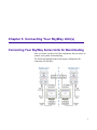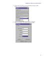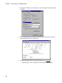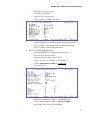
1
SkyWay Series Multi-Point Installation Guide SkyWay Series Multi-Point Installation Guide for SkyWay-Net and SkyMate Wireless Bridge/Routers i About This Manual About This Manual The information contained in this document is subject to change without notice. Solectek Corporation shall not be liable for errors contained herein or for incidental or consequential damage in connection with the furnishing, performance, or use of this material. Reproduction, adaptation, or translation without prior written permission is prohibited, except as allowed under the copyright laws. Solectek Corporation makes no warranty of any kind with regard to this material, including, but not limited to, the implied warranties or merchantability and fitness for a particular purpose. Document Version: 1.02 Part Number: 1288501 For use with SkyWay-Net and SkyMate software versions 3.0 and higher. Trademarks & Copyrights SkyWay is a registered trademark of Solectek Corporation SkyMate and Solectek are trademarks of Solectek Corporation IBM and AT are registered trademarks of International Business Machines Corporation. Microsoft and MS-DOS are registered trademarks of Microsoft Corporation. Novell and NetWare are registered trademarks of Novell, Inc. Other trademarks are the property of their respective holders. Copyright Solectek Corporation 2001. All rights reserved. Contacting Technical Support Contact Solectek Corporation’s Technical Support Department during normal business hours: Monday through Friday, 8:00 a.m. to 5:00 p.m., Pacific Time or submit questions to our 24-hour fax number or by e-mail. Voice support: (858) 450-1220 24-hour fax number: (858) 457-2681 Web support: http://www.solectek.com/support/ E-mail address: [email protected] Please have the following information ready when you call: ii • Model Number • Type of Ethernet connection your SkyWay-Net Bridge/Router • Network operating system, e.g., Novell Netware, etc. • Application using when problem was encountered, e.g., MS-Excel, etc. SkyWay Series Multi-Point Installation Guide • Symptoms and/or error codes that accompanied the problem • Most recent bench test results Safety Electrical Guidelines Observe the following electrical guidelines when working on the SkyWay-Net Bridge/Router. • Do not work on the system or connect or disconnect cables under these conditions: - During a thunderstorm - When wearing a wool sweater or other heavy wool clothing - When power is applied • Always ensure the power is off before connecting or disconnecting the 3 pin power cord connector. • Do not touch the SkyWay-Net power supply when the power cord is connected. Because the SkyWay-Net Bridge/Router does not have a power switch, line voltages are present within the power supply when the power cord is connected to the Bridge/Router. • The SkyWay-Net Bridge/Router relies on the building’s installation for short-circuit (overcurrent) protection. Make sure that a fuse or circuit breaker not larger than 120 VAC, 15A U.S. (240 VAC, 10A international) is used on the phase conductors (all current-carrying conductors). • Before working on the SkyWay-Net chassis, unplug the power cord from the AC outlet or disconnect the fuse or circuit breaker. • Locate the emergency power-off switch for the AC source connected to the SkyWay-Net Bridge/Router. If an electrical accident occurs, use this switch to turn off power to the bridge. • All antenna and data cables should be Listed for outdoor installation in accordance with the National Electrical Code, or acceptable to the local Authority Having Jurisdiction. • Ungrounded or improperly grounded antennas constitute a hazard to personnel and equipment. A lightning strike on or near an improperly grounded antenna can cause severe injury or death as well as equipment destruction. iii About This Manual Regulatory Information The SkyWay-Net Wireless Bridge/Router operates in the 2.4 GHz band, complies with the IEEE 802.1D MAC bridging standard and supports SNMP monitoring if IP routing is enabled. FCC Radio Frequency Interference Statement FCC ID: KA324WAN5 This device is certified to comply with Part 15 of Federal Communications Commission (FCC) Rules. Operation is subject to the following two conditions: 1. It may not cause harmful interference. 2. It must accept any interference that may cause undesired operation. Industrie Canada Radio Frequency Interference Statement CANADA 2499391165A This device is certified to comply with Industrie Canada (IC) RSS/CNR 139. Operation is subject to the following two conditions: 1. It may not cause harmful interference. 2. It must accept any interference that may cause undesired operation. U.S. Government Restricted Rights Legend The Product is provided with Restricted Rights. Use, duplication, reproduction or disclosure by the Government is subject to restrictions in subdivision (c)(1)(ii) of the Rights in Technical Data and Computer Product clause at 252.227-7013 and in subparagraphs (a) through (d) of the Commercial Product-Restricted Rights Clause at 52.227-19. Contractor/Manufacturer is Solectek, 6370 Nancy Ridge Drive, Suite 109, San Diego, California. In order to comply with FCC RF exposure requirements, a minimum separation distance of 27 in. must be maintained between the antenna and any persons. When installing the antenna, ensure that this clearance is maintained while the product is in operation. This device must be installed and used in strict accordance with the manufacturer's instructions. However, there is no guarantee that interference to radio communications will not occur in a particular commercial installation. In case the device does cause harmful interference with an authorized radio service, the user/ operator shall promptly stop operating the device until harmful interference has been limited. Solectek Corporation is not responsible for any radio or television interference caused by unauthorized modification of this device or the substitution or attachment of connecting cables and equipment other than specified by Solectek Corporation. The correction of interference caused by such unauthorized modification, substitution, or attachment will be the responsibility of the user. iv SkyWay Series Multi-Point Installation Guide Radio Transmission Notice This product is a low power (less than 1 Watt), direct-sequence, spread-spectrum radio system pre-set to transmit and receive signals in the 2.4-2.4835 GHz frequency band. This product has been certified by the U.S. Federal Communications Commission for use in the United States of America in that band. The manufacturer makes no representation as to the availability of the above-mentioned frequency band for such use in other countries. Any prospective user of this product outside the United States of America should, prior to such use, contact the government department or other agency responsible for assigning radio frequencies in the country in which use is proposed to determine whether such department or agency has any objection to operation of the product in the 2.4-2.4835 GHz band, and whether there are any other local devices generating signals in that band which might be expected to interfere with the operation of this product. Solectek shall not be responsible for any operation of this product which is in violation of local law, creates interference harmful to other local devices, or results in a malfunction of this product caused by outside interference. Declaration of Conformity Solectek Corporation 6370 Nancy Ridge Drive San Diego CA 92121 Declares that the product SkyWay-Net manufactured 2001 conforms to the following product specifications: EMC-CISPR22 ClassA IEC 60417 UL 94 CFR47 Part 15 IEC 60529 UL 950 CFR 21.1040 RSS 210 IP66 TYPE 4X Low Voltage Directive including amendments by CE Marking Directive v About This Manual vi SkyWay Series Multi-Point Installation Guide Table of Contents About This Manual.....................................................................ii Trademarks & Copyrights .......................................................... ii Contacting Technical Support .................................................... ii Safety .........................................................................................iii Electrical Guidelines .......................................................................... iii Regulatory Information ............................................................. iv FCC Radio Frequency Interference Statement .............................. iv Industrie Canada Radio Frequency Interference Statement ........ iv U.S. Government Restricted Rights Legend ................................... iv Radio Transmission Notice .................................................................v Declaration of Conformity ......................................................... v Preface ................................................................................ xi Intended Audience..................................................................... xi Summary of this Guide ............................................................xii Chapter 1: Getting Started.....................................................1 Checking Your SkyWay Series Kit(s) ....................................... 1 SkyWay-Net Kit ...................................................................................2 SkyMate Kit..........................................................................................3 vii Table of Contents Summary of the Installation Process ......................................... 3 Chapter 2: Pre-Installation Considerations ............................5 Pre-installation Checklist ........................................................... 5 Assess Your Network Requirements ..................................................5 Map Wireless Network Pre-Design ....................................................6 Perform a Site Survey..........................................................................6 Finalize the Design ...............................................................................6 Chapter 3: Connecting Your SkyWay Unit(s) ........................7 Connecting Your SkyWay Series Units for Benchtesting ......... 7 Powering Up............................................................................... 8 Console Interface......................................................................11 Navigating the Screens ......................................................................11 Chapter 4: Benchtesting Your SkyWay Unit(s)....................13 Why Benchtest?........................................................................ 13 Minimum Settings and Defaults for Benchtest ...............................13 Starting the Benchtesting ......................................................... 14 Chapter 5: Installing Your SkyWay Units.............................19 Before Installing ....................................................................... 19 Safety Considerations ........................................................................20 Installing the Units ...................................................................21 viii SkyWay Series Multi-Point Installation Guide Installation Precautions.....................................................................21 Installing a SkyWay-Net ...................................................................21 Mounting to a Mast............................................................................21 Mounting to a Wall ............................................................................23 Installing the SkyMate.......................................................................25 Mounting the Antenna.............................................................. 27 Selecting the Antenna ........................................................................27 Before You Mount the Antenna .......................................................28 Grounding the Unit and Antenna.....................................................29 Selecting a Ground Source ................................................................29 Connecting Cabling ...........................................................................29 Routing Connected Cables ................................................................29 Connecting an Antenna .....................................................................30 Connecting to Power..........................................................................31 Connecting to the Administration Console .....................................33 Connecting to Your LAN ..................................................................34 Antenna Alignment and RF Link Verification ...............................35 Chapter 6: SkyWay Series Warranty Information ................37 Warranty ................................................................................... 37 One Year Limited Warranty ............................................................37 Limitations..........................................................................................38 End User License Agreement................................................... 39 Index ...................................................................................43 ix Table of Contents x Preface This guide is designed to help you install, configure, manage, maintain, and troubleshoot your SkyWay Series wireless network comprised of Base station (SkyWay-Net) and substations (SkyWay-Net and/or SkyMate). Intended Audience This document contains information required for preparation, installation, and configuration for your SkyWay Series Wireless Bridge/Routers. The information in this manual written for a technical audience that meets the following requirements: Note • You are functioning in an Information Services or Building Facilities capacity. • You have more than one year’s experience with networking, either wireless or traditional. • You are familiar with basic networking concepts such as bridging, IP routing, WAN protocols, etc. • You are familiar with your LAN or WAN’s topology, configuration, and design. • If you will be using Simple Network Management Protocol to manage SkyWay, you are familiar with the protocol’s terms and usage. • You are familiar with basic RF/wireless network design, even if you are not familiar with the particulars of any specific system. If you do not meet these requirements, we recommend that you hire a consultant to assist you with installing and configuring your SkyWay network. xi Preface Summary of this Guide The following includes a brief summary of what is in each chapter: • Chapter 1: Getting Started Discusses opening your SkyWay Series kit(s), checking all of the components, and an overview of the installation process. • Chapter 2: Pre-Installation Considerations Briefly discusses four aspects you should consider/perform prior to implememnting your wirless network. • Chapter 3: Connecting Your SkyWay Unit(s) Discusses how to connect SkyWay Series units for benchtesting. • Chapter 4: Benchtesting Your SkyWay Unit(s) Discusses how to benchtest your units prior to installing them into their final field location. • Chapter 5: Installing Your SkyWay Units Describes how to install your SkyWay Series units in the field • Chapter 6: SkyWay Series Warranty Information Warranty and end user license agreement. • Index For configuring and monitoring information and procedures, see the SkyWay Series Multi-Point Operator’s Guide. xii Chapter 1: Getting Started This Installation Guide is the part of a series of guides on using the SkyWay Series products. This series includes: • SkyWay Series Installation Guide (this book) • SkyWay Series Operator’s Guide This book describes how to: • Inspect your SkyWay Series kit(s) for all components • Connect your SkyWay Series units/system • Benchtest your SkyWay Series units/system prior to final installation • Install your SkyWay Series units/system • Bring your SkyWay Series units/system up for operation Checking Your SkyWay Series Kit(s) When you first receive your SkyWay Series kit, please inventory all components to ensure you have everything you need for installation. 1 Chapter 1: Getting Started SkyWay-Net Kit Your SkyWay-Net kit should include the following components: 9 4 5 10 3 2 7 1 11 6 1. Antenna Cable 2. Ethernet Cable 3. Power Cable 4. Console Cable 5. Mast Mounting Kit 6. Benchtest Antenna 7. SkyWay-Net Unit 8. RS-422 Converter 8 12 9. AC Power Converter 10. RS Power Supply 11. AC/DC Power Supply 12. Cable Clip • SkyWay-Net unit • Mast Mounting kit • User Documentation CD • SkyWay-Net Quick Start Guide • SkyWay-Net Installation kit - which includes: - RS 422 Converter - SkyWay Series Benchtest Antenna - AC Power Converter - RS Power Supply - AC/DC Power Supply Customized components based upon your order include: • Console Cable (length based on your request -100/200/300 ft) • Antenna kit (not shown) Take a moment to ensure you have all of the required components. If you do not have a component or the correct component, contact Solectek immediately so we resolve the problem as fast as possible. 2 SkyWay Series Multi-Point Installation Guide SkyMate Kit Your SkyMate kit should include the following components: • SkyMate unit • Power Supply & Cord • Serial Port Cable • Software CD • SkyMate Quick Start Guide • Antenna Cable (not shown) • Antenna Kit (not shown) Summary of the Installation Process The installation process is divided into the following four phases: • Pre-Installation Considerations • Connecting Your SkyWay Unit(s) • Benchtesting Your SkyWay Unit(s) • Installing Your SkyWay Units Pre-Installation Considerations There are four aspects that must be considered prior to installing your wireless network: 1. Assess Your Network Requirements Prior to choosing the equipment, research what your wireless network will need. Find out how many sites you want to include, their requirements (bandwidth, protocols, etc.). 2. Map Wireless Network Pre-Design Create a map with every site nodes shown - each with all of the vital information (lat/long, antenna heights, etc.) 3 Chapter 1: Getting Started 3. Perform a Site Survey A Site Survey allows you to assess the requirements of each site in the wireless network. 4. Finalize the Design Once you have a Site Survey for each site, you can incorporate these factors into your final design requirements. Connecting Your SkyWay Unit(s) This chapter focuses on preparing your units for benchtesting. With all of the units in one room, it is much easier to connect, configure, and verify all of the units are performing properly - as opposed to miles apart and on top of towers and buildings. 1. Connecting Your SkyWay Series Units for Benchtesting This section provides instructions and diagrams for connecting the units. 2. Powering Up Once you power on the unit, you need to establish communication to the unit via the Console. 3. Console Interface Once connected, use the Console to configure and view your unit. Once all are connected and configured, you can command any of the units from the Base unit. Benchtesting Your SkyWay Unit(s) This chapter includes step-by-step procedures on how to benchtest the units. 1. Why Benchtest? A brief discussion on why you really want to benchtest before you install the units. 2. Starting the Benchtesting Step-by-step procedures to walk you through the process. Installing Your SkyWay Units This chapter provides detailed information and procedures for installing the units. 1. Before Installing Two words: SAFETY FIRST! Do’s and don’t before you begin. 2. Installing the Units Detailed instructions for both SkyWay-Net and SkyMate units. 3. Mounting the Antenna Discusses all aspects of installing the antenna. 4 Chapter 2: Pre-Installation Considerations Planning and feasibility studies are critical to successfully integrate the SkyWay Series Bridge/Router with your network. There are additional factors, for example, Radio Line of Sight and overall RF environmental issues, which must be taken into account for wireless connectivity. Deploying a successful network requires feasibility studies and careful planning, particularly for wireless connectivity solutions where additional factors must be considered. Radio Line of Sight and overall RF environment must be assessed and documented to assist in determining the initial installation as well as providing a baseline for future RF environmental measurements when suspected local RF environment changes occur. Pre-installation Checklist Assess Your Network Requirements Solectek recommends the following in determining the feasibility of a wireless internet working solution using Solectek wireless bridges and routers: • Identify, list and classify the data resource centers by type and number of users. • Layout the topology of voice, data and video networks indicating bandwidth requirements, protocols, and media of each network segment. • Plan and layout the IP addressing scheme for IP networks. • Ensure all protocols deployed in the planned network, including planned wireless segments, can be encapsulated in Ethernet frame 802.3 and Ethernet II. • Identify protocols and network segments which will require encapsulation in IP packets and consequent routing. 5 Chapter 2: Pre-Installation Considerations Map Wireless Network Pre-Design Next, provide details about locations to be connected; for example, building-tobuilding, or server-to-ISP. • Identify and mark the locations of the main nodes of the network on a geographical map of the region. Attach full street addresses and building characteristics to each location. • Gather site coordinates (latitude and longitude) for each location. • Use the site coordinates to determine optimal geographical layout of desired link paths for wireless network segments, and complete the wireless network geographical map. • Determine minimum antenna height requirement for each location, ensuring each link’s path at least 60% of Fresnel zone is unobstructed. Perform a Site Survey Assess the Line of Sight and RF environmental factors. • Check for competing RF signals using a spectrum analyzer. • Detect and measure the potential sources of interference in selected RF bands for each site. • Mark the direction and nature of detected RF interference on the wireless network map (created in step two). • Determine the height of obstacles (trees, buildings, highways) in each link’s path. Finalize the Design Adjust your plan and select equipment. 6 • Adopt changes in the network layout to overcome RF interference, and to guarantee the minimum required bandwidth for each link. • Adjust antenna height requirements based on identified obstacles in the site survey. • Select the antenna types for each site, based on the link distance and minimum antenna co-location requirements. • Select an RF channel and antenna polarity plan for each link. • Select cable types and lengths. Chapter 3: Connecting Your SkyWay Unit(s) Connecting Your SkyWay Series Units for Benchtesting Once you ensure you have all of the components, the next step is to connect your system for benchtesting. The following illustration shows the proper configuration for connecting two SkyWay: 7 Chapter 3: Connecting Your SkyWay Unit(s) Powering Up 1. Once your system is connected, open a HyperTerminal™ session on each PC. In MS-Windows®, choose: Start/Programs/Accessories/Communications/ HyperTerminal. A pop-up window will open and click on the Hypertrm.exe, as shown in the following illustration: 2. When you initially open HyperTerminal, you automatically create a new connection. Enter a name for this connection (e.g., SkyWay-Net 1, SkyMate-2, etc.) and select an icon. 3. Click on OK and the Connect To window will appear. 8 SkyWay Series Multi-Point Installation Guide 4. In the Connect To window, select the applicable COM port (COM1, COM2, etc.) from the pull-down menu. 5. Click on OK and the COM Properties window will appear. 6. Change Port Settings to the match the following window: 9 Chapter 3: Connecting Your SkyWay Unit(s) 7. Under the File Menu, select Properties; on the Settings Tab, set Emulation to VT100. 8. Save, exit, and restart your HyperTerminal session and your session will start the SkyWay Series Login screen. 9. Log in to the system; your user name & password are solectek. Repeat Steps 2-8 for each SkyWay-Net unit before proceeding. 10 SkyWay Series Multi-Point Installation Guide Console Interface Once you have logged in to the system, the Main menu will appear. All screens have three areas: Title, Menu/Field, and Command Line. Screen Title: Menu/Field: Command Line: Title of Menu or Screen - changes based on the screen accessed. Menu items or fields - contains menu items or fields you can monitor, execute, etc. Instructions/options or command line - onscreen instructions for navigating or displays command line instruction. Navigating the Screens In the Menu/Field area of the Main Menu, note that each menu item has a number next to it. A blinking cursor indicates where on the screen you are at. Moving the cursor up/down/left/right using the Arrow Keys and pressing Enter allows you to access the command. However, pressing the corresponding number next to a menu item also allows you to navigate throughout the program. For example, if you press 1., the screen changes to the Configuration Menu, 2. changes to the Status and Control Menu, etc. This allows you to enter a string of numbers, for example - by typing 1234 allows you to access the Configuration Menu, Port Configuration Menu, RF Port Configuration Menu, and finally stop at the RF Level Control Screen. This is easier than pressing the arrow keys numerous times to access the same screen in four keystrokes. 11 Chapter 3: Connecting Your SkyWay Unit(s) 12 Chapter 4: Benchtesting Your SkyWay Unit(s) Since the SkyWay Series bridge/router is a ruggedized device installed outside the building, Solectek recommends spending some time planning the installation and testing the configuration before permanently mounting the units. Why Benchtest? Benchtesting your SkyWay Series Bridge/Router (system) prior to installing it in its permanent location is strongly recommended. Benchtesting allows you to test and configure the equipment to your requirements prior to final installation. It allows you to become familiar with the equipment’s operation and capabilities in a user-friendly environment. Installers who benchtest all equipment and configurations have a significantly higher success rate during field installation than those who skip the benchtest. The following items are required for the benchtest: • At least 2 Skyway units (-Net and/or -Mate) • SkyWay Series power cable and AC/DC converter • Console cable and RS-422 to RS-232 converter • Test antenna for each SkyWay Series RF port • Two terminals or workstations with VT-100 emulation capability (one for each SkyWay Series), or one workstation with two RS-232 ports to accommodate two SkyWay Series. Minimum Settings and Defaults for Benchtest • RF Frequency: Use the most efficient RF frequency for your SkyWay Series as determined during the site survey. • Tap Value: During installation, the installer decides on an appropriate tap value for your SkyWay Series so that there is no interference with other SkyWay Series traffic. 13 Chapter 4: Benchtesting Your SkyWay Unit(s) • Mode: Designate one SkyWay Series as the base station and the other as the substation. Starting the Benchtesting Benchtesting is a critical phase to properly installing your SkyWay Series system. Benchtesting allows you to check all of the component connections and operations prior to mounting the units on towers miles apart. To benchtest your system, use the following procedure: 1. Setting the Date and Time • From the Main Menu, select the Configuration Menu. • Select System Configuration. • Select General Parameters Configuration. • Set the current time and date. • Type .w (Write). • Press \ (backslash) 3 times to return to the Main Menu. 2. Configure the RF Diagnostic Ports for Base and Sub units. • From the Main Menu, select the Configuration Menu. • Select Port Status and Control. • Select RF Port Configuration. • Select RF Diagnostic Port Configuration. • Set the Base unit Port Type to WCOPP Base Diagnostic Port and Sub unit(s) Port Type to WCOPP Sub Diagnostic Port. • Type .w (Write). • Press \ 4 times to return to the Main Menu. 3. Configure IP Address for Port 3. • 14 From the Main Menu, select the Configuration Menu. SkyWay Series Multi-Point Installation Guide • Select Router Configuration. • Select IP Configuration. • Select IP Port Configuration. • Type .n (Next) - changes to the Port 3. • Change IP Address to address from the network administrator. • Type .w (Write) - this changes the port configuration status. • Press \ 3 times to return to the Main Menu. 4. Activate New RF Diagnostic Ports. • From the Main Menu, select the Status and Control. • Select Port Status and Control. • Select Generic Port Status and Control. • Type .n (Next) twice to change to Port Number 3. • Change Administrative Status to Cycle Port. • Type .w (Write). Port Status momentarily changes to Transitioning Up. • Type .r (Read) and verify status is Up Port & Online. • Press \ until you return to the Main Menu. 15 Chapter 4: Benchtesting Your SkyWay Unit(s) Note: Perform Steps 1-4 for all units before proceeding. 5. Start Diagnostic Tests • From the Main Menu, select Diagnostics. ON THE BASE UNIT: - Select RF Base Radio Test. - Ensure Test Timeout to 8 ms. Change Test to Run to Single Frame Ping Pong Mode. Type .w (Write) - this starts the test on Base unit. ON THE SUB UNIT: • - Select RF Sub Radio Test. - Change Test to Run = Single Frame Ping Pong Mode. Type .w (Write) - starts test on Sub unit. Press \ until you return to the Main Menu. 6. Verify Base & Sub Unit(s) Status 16 • From the Main Menu, select Status and Control. • Select Port Status and Control. • Select RF Port Status. • Select RF Port Status (again). • Type .z (Zero) and .m (Monitor). While the unit is in Monitor Mode, the numbers will change to reflect the transmission. SkyWay Series Multi-Point Installation Guide • After approximately 15 minutes, type .r - this captures the current screen transmission and allows you to read the numbers and determine the error count. • Calculate the error count. To calculate, use the following formula: - Total the Digital Phase Lock Loop through CTS Lost numbers. Note: Error count is acceptable if less than 1% of total frames received. • Return to the Main Menu. 7. Terminate Diagnostic Tests • From the Main Menu, select Diagnostics. ON THE BASE UNIT: - Select RF Base Radio Test. Change Test to Run to Terminate Test. Type .w (Write) - this starts the test on Base unit. ON THE SUB UNIT: - • Select RF Sub Radio Test. Change Test to Run to Terminate Test. Type .w (Write) - starts test on Sub unit. Press \ until you return to the Main Menu. 17 Chapter 4: Benchtesting Your SkyWay Unit(s) 18 Chapter 5: Installing Your SkyWay Units This chapter contains the following installation information: Before Installing.............................................................. 19 Safety Considerations ..................................................... 20 Installing the Units .......................................................... 21 Mounting the Antenna .................................................... 27 Grounding the Unit and Antenna .................................... 29 Connecting Cabling ........................................................ 29 Antenna Alignment and RF Link Verification ............... 35 Before Installing To install your SkyWay Unit, you need the following items: • Cellular telephones or two-way radios - so you can communicate when aligning SkyWay Unit antennas during the installation process. • VT-100 console or workstation with VT-100 emulation capability and terminal emulation software (HyperTerminal™ or ProComm™) - to configure the SkyWay Unit Bridge/Router • 13 mm hex socket wrench - for mounting bracket • Slotted screw driver - for mounting clamps • Modem (optional) - if you want to operate the SkyWay Unit Bridge/Router through a dial-up connection. The following items are optional and are required only if you find it necessary to cut the indoor connectors off to accommodate pulling the cable through conduit: • Ethernet cable: an RJ-45 cable crimper to terminate the RJ-45 connection to the Ethernet LAN during the installation process. • Serial cable: a small screwdriver to disassemble the DB-9 case, a pin removal extractor tool or a replacement DB-9 jack. 19 Chapter 5: Installing Your SkyWay Units • Power cable: a soldering iron Safety Considerations The following sections provide guidelines to ensure your safety when installing and working with the SkyWay Unit Bridge/Router. General Safety Guidelines Observe the following general guidelines to ensure safety: • Keep tools away from walk areas where you and others could trip over them. • Do not wear loose clothing that could get caught in the chassis mounting hardware. Fasten your tie or scarf and roll up your sleeves. • Wear safety glasses when working under any conditions that might be hazardous to your eyes. • Do not perform any action that creates a potential hazard to people or makes the equipment unsafe. Electrical Safety Guidelines Observe the following electrical guidelines when working on the SkyWay Unit: • 20 Do not work on the system or connect or disconnect cables under these conditions: • During a thunderstorm • When wearing a wool sweater or other heavy wool clothing • When power is applied • Always ensure the power is off before connecting or disconnecting the 3 pin power cord connector. • Do not touch the SkyWay Unit power supply when the power cord is connected. Because the SkyWay Unit Bridge/Router does not have a power switch, line voltages are present within the power supply when the power cord is connected to the Bridge/Router. • The SkyWay Unit Bridge/Router relies on the building’s installation for short-circuit (overcurrent) protection. Make sure that a fuse or circuit breaker not larger than 120 VAC, 15A U.S. (240 VAC, 10A international) is used on the phase conductors (all current-carrying conductors). • Before working on the SkyWay Unit chassis, unplug the power cord from the AC outlet, disconnect the fuse, or trip the circuit breaker. • Locate the emergency power-off switch for the AC source connected to the SkyWay Unit Bridge/Router. If an electrical accident occurs, use this switch to turn off power to the bridge. • This product is intended to be supplied by an SELV source rated at 48VDC, minimum 1A. SkyWay Series Multi-Point Installation Guide Installing the Units Once you have performed a successful bench test and configured the units to your satisfaction, you are ready to install and connect them. Installation Precautions Installers must ensure the SkyWay Unit and its peripheral equipment is kept at a safe distance away from hazardous systems, cables, and equipment. The installer(s) should consult the National Electrical Code, Sections 725 and 800, specifically for clearances from power and lighting conductors, and transient protection. Installing a SkyWay-Net Mount The SkyWay-Net to an outdoor mast or wall. Mounting to a Mast Tools: • 13 mm hex socket wrench • Slotted screwdriver 21 Chapter 5: Installing Your SkyWay Units To mount the SkyWay-Net to a mast: 1. Place the mast-mounting bracket on a table with the flat side down. P/N 1225401 P/N 1225501 P/N 1225001 P/N 1225201 Use the third central pair of slots for seating a third clamp if you want extra clamp security. 2. Thread two clamps into the outside pair of slots on the bracket. Ensure to thread them in the same direction. 3. Place the SkyWay Unit face down. Place the bracket and clamp assembly over the rear of the SkyWay Unit so that the four mounting holes align. 4. Place one spring lock washer (P/N 1225201) on each mounting bolt. 5. Using a 13 mm hex socket wrench, tighten a bolt and washer into each hole of the bracket to a maximum torque of 15-20 ft-lbs (to prevent stripping). 22 SkyWay Series Multi-Point Installation Guide 6. Position the bracketed SkyWay Unit against the mast with the connectors facing downward. Connector side down Note: The mast should be a minimum of 1 in. (25.4 mm) outside diameter. 7. Feed the end of each clamp around the mast into the locking mechanism at the other end. Using a slotted screwdriver or nut driver, tighten the clamp screws to a maximum torque of 45 ± 5 in-lbs. CAUTION: The mast to which you mount the SkyWay Unit and/or antenna should be grounded. If the mast is not grounded, see “Installation Precautions” on page 21 and “Grounding the Unit and Antenna” on page 29. Mounting to a Wall The wall mount kit is optional and may be purchased separately. Tools: • 13 mm wrench 1. Place the SkyWay Unit face down. 23 Chapter 5: Installing Your SkyWay Units 2. Align the two brackets over the SkyWay Unit unit bolt holes, either along the length or width of the unit. P/N 1225101 3. Insert bolts and tighten with a 13 mm wrench. Note: The bolts can be found in the Mast Kit shipped with SkyWay Unit. 4. Fasten the SkyWay Unit to the wall using the slider slots and bolts (not supplied), making sure the SkyWay Unit connectors face downward. Connector Side Faces Down CAUTION: The surface to which you mount the SkyWay Unit and/or antenna should be grounded. If the surface is not grounded, see “Installation Precautions” on page 21 and “Grounding the Unit and Antenna” on page 29. 24 SkyWay Series Multi-Point Installation Guide Installing the SkyMate Setting Up Your SkyMate 1. Remove the SkyMate equipment from the box. Antenna Cable Power Cord Serial Cable Optional Ethernet Cable Caution: In the following step, hand-tighten the antenna cable. Do not use a wrench or tool. Overtightening this cable may damage the connection. 2. . 3. . Connect the Antenna, Power, Serial, and (if applicable) Ethernet cables to the SkyMate & your COM Port on your computer. For antenna installation and configuration procedures, refer to the “Mounting the Antenna” on page27. Plug the power cord in to the electrical outlet. Your SkyMate will perform a boot-up sequence (this may take a few minutes). Status . RF Link Ethernet During the bootup sequence, the Status LED will display the following conditions: Red - Initializing Green - Operational Once complete, the SkyMate will show the status of the Status, RF Link, and Ethernet connections. Status LED Green - Operational Flashing Red - Unknown failure (see the Mounting the Antenna section). Ethernet LED and RF Link LEDs Green - Link is up. Flashing Amber - Activity on line/link. No light - Link is down. Status LED Indicators The Status LED may display a combination of Red and Green flashes to indicate an event or problem. For example, 2 Red flashes followed by 1 Green flash on the Status LED. The following tables describe the possible Status LED combinations: 25 Chapter 5: Installing Your SkyWay Units WCOPP-AP Indications Flashing Status LED Indication/Problem 2 Red & 1 Green All channels exhausted; search paused. 2 Red & 2 Green Searching RF channels for a valid Base. 2 Red & 3 Green Waiting for acceptance from Base; Standby. 2 Red & 4 Green Association done IP Address will now be obtained (if DHCP is enabled). Solid Green Association with Base established (if DHCP is enabled). DHCP Indications Flashing Status LED Indication/Problem 3 Red & 1 Green Waiting for IP Address lease offer. 3 Red & 2 Green Waiting for IP Address lease acknowledgement. 3 Red & 3 Green Configuration not yet downloaded. 3 Red & 4 Green Renewing IP Address lease. Solid Green Connection done. Plug-n-Play vs. Configure Settings Plug-n-Play 26 Once you have accessed the Console, determine if you are plug-n-play capable or you need to change the settings manually. The SkyMate comes preset with default or plug-n-play settings from the factory. Once you connect the cables to the SkyMate and install the antenna, an RF connection should be established within a few minutes. In this plug and play mode, all configuration is done on the SkyWayNet Base station. If your SkyWay-Net Base station is configured correctly as a DHCP Server with a connection to a TFTP Server with SkyMate Runtime Database files, the SkyMate will automatically be assigned an IP address and download a runtime database from the TFTP Server, i.e., plug-n-play without having to worry about configuring the unit. Plug-n-Play settings include: • Configuration Server is Enabled (set on Base) • WCOPP-AP Mode is set to Standby. • DHCP Client is Enabled SkyWay Series Multi-Point Installation Guide • Static Routing is Enabled If your wireless network meets this criteria, skip to the “Mounting the Antenna” on page27 to complete your installation. If your wireless network does not meet the criteria, proceed to the next section to configure your SkyMate. Changing the Default Settings (Non Plug-n-Play) This section instructs you how to change from the default plug-n-play settings to the non plug-n-play settings. It serves as an introduction to basic steps to manually configure the SkyMate. For more information on reconfiguring the SkyMate, refer to the SkyWay Series Multi-Point Operator’s Guide, Chapter 2. This procedure will change the following SkyMate settings: • DHCP Client (TFTP Server) is Disabled. • RF Port IP Address is manually assigned. 1. 2. 3. 4. 5. 6. 7. 8. 9. From the Main Menu, type 1541 and press Enter to go to the BOOTP/DHCP Protocol Configuration screen. Change DHCP Client to Disable and type .w to execute the command. Type .1512 and press Enter to go to the IP Port Configuration screen, Port 2. Scroll down using the arrow keys and configure the IP Address (see your Network Administrator for address). When finished, type .w to execute the command. Type .n to access Port 3 and configure the IP Address (see your Network Administrator for address). When finished, type .w to execute the command. Type .1511 and press Enter to access the IP Protocol Configuration screen. Verify the Default Gateway Enabled field is set to Yes. Enter the Default Gateway IP Address (RF Port of the BASE unit). Type .w to execute the command. Return to the Main screen and restart the RunTime application. Type 5, select RunTime and type .w to execute the command. Login (user & password = solectek) and type 2241 to go to the RF Port Status screen. Type .m to monitor the screen and watch the SkyMate begin searching the channels for a frequency lock. Mounting the Antenna This section of the chapter discusses the aspects of mounting the antenna, including: • Selecting the Antenna and Pre-mount Considerations • Grounding the Unit and Antenna • Connecting the Cabling to the Unit, Power, LAN, and Console Selecting the Antenna Solectek supplies one of several different antennas, including both sectoral and omni models. Solectek’s systems engineers will assist you with antenna selection, taking into account factors such as usage (point-to-point or multi-point), distance to substations, and interference from nearby antennas. 27 Chapter 5: Installing Your SkyWay Units Apart from the two omnidirectional antenna (7002301 6 dBi and 7002401 11 dBi), all Solectek antennas can be used as bridge antennas between two networks or point-to-point communications in the ISM band (2.4 GHz) only. Before You Mount the Antenna Use the following guidelines for installing the SkyWay Unit antennas: 1. Avoid reflective environments: Where possible, avoid mounting antennas in a “reflective environment,” e.g., near objects that can reflect radio energy back to the antenna. Signal reflections from nearby objects are seen as noise by radio transceivers and can adversely affect the range or quality of your wireless link. Examples of reflective objects include: • Trees or bushes • Buildings • Air conditioning units and ductwork • Other radio antennas • Building structures made of any material such as steel, brick, or wood • Construction vehicles and equipment 2. Use the following safe handling procedures: • Do not perform antenna installation by yourself. Some antennas are large and hard to handle, especially when changing polarity or performing the final mounting on the mast. You need a second person to align the antenna; schedule as much antenna work as possible when at least two workers are available. • Use a bubble level (carpenter’s level) to ensure all antennas are level. For antennas mounted to the wall, you may need additional spacers or washers to obtain a level installation. 3. Mount antennas securely: A small movement of the antenna caused by an insecure mount or weak mast results in a huge sweep at the other end of the link miles away. • Ensure the antenna is bolted securely to the mast. • Always use appropriate guy wires (see your local building codes for recommendations and requirements). • Weight non-penetrating roof mounts securely with concrete blocks or other ballast. 4. Handle the antenna RF cable carefully: Maintain a 12-inch bend radius if possible. Do not walk on or kink the cable. A kinked cable can cause severe signal attenuation and the link to fail. 28 SkyWay Series Multi-Point Installation Guide Grounding the Unit and Antenna Warning: Ungrounded or improperly grounded antennas constitute a hazard to personnel and equipment. A lightning strike on or near an improperly grounded antenna can cause severe injury or death as well as equipment destruction. Any Solectek equipment damaged by lightning is considered to be damaged by an Act of God and not covered under warranty. Solectek antennas (2.4 GHz) and Bridge/Router(s) do not require additional grounding when mounted on antenna masts properly grounded per local electrical and building codes. Supply grounding if the SkyWay Unit and its antenna are mounted on a nonpenetrating roof mount, a wall, or an ungrounded wooden mast. In these cases, attach one end of a bond wire to one of the bolts on the SkyWay Unit bracket. Attach the other end to another mast (properly grounded), a building ground, or an NEC ground. Selecting a Ground Source Caution: Always switch OFF the power to the SkyWay Unit before connecting or disconnecting the 3-pin power cable. If the SkyWay Unit and its antenna are mounted on a non-penetrating roof, a wall, or an ungrounded wooden mast, attach a bond wire (minimum of 10 AWG) to one of the bolts on the SkyWay Unit mounting bracket and connect the other end of the wire to a properly-grounded mast, the building ground, or a NEC ground. The installer(s) should consult the National Electrical Code, Section 810, specifically for clearances from power and lighting conductors, and if necessary, grounding. Connecting Cabling The SkyWay Unit connects to the antenna by a LMR-400 RF cable. The SkyWay Unit connects to power and to the terminal, terminal emulator or LAN by three cables: • Power • Console • Data (Ethernet copper or fiber-optic) The three cables route into the building. Routing Connected Cables Determine where to route the cables within the building before you begin connecting the SkyWay Unit. SkyWay Unit’s design enables you to route each 29 Chapter 5: Installing Your SkyWay Units cable to its most logical/convenient location. These locations may not be in the same room or even on the same floor. For example, it may make the most sense to route the power to a utility room on the top floor, the console to a secured room on the second floor, and the Ethernet to your LAN room on the first floor: SkyWay-Net Utility Room for Power Mount Secured Room for Console LAN room The length of the cable set you ordered determines the maximum distance for all connections, e.g., 100, 200, or 300 ft (300 ft is max. distance unless you use fiberoptics; fiber-optics max. distance is 4,000 ft.) Be sure to secure the cables to the mast at intervals to protect the cables and the connection. Connecting an Antenna The LMR-400 RF cable connects the SkyWay Unit with the antenna above it on the mast. To connect an RF cable: 1. Making sure the threads are properly aligned, tighten the cable’s connector bolt snugly over the SkyWay Unit RF connector port using a 13/16 in wrench. Hand-tighten another 1/4 turn to lock it in place. 2. Connect the other end of the RF cable to the antenna’s connector using the same technique. 30 SkyWay Series Multi-Point Installation Guide Note: Allow sufficient slack in the cable for a maximum turning radius of 1 ft. Antenna Slack for 1 ft turning radius LMR-400 cable 3. Seal the connections to both the antenna and the SkyWay Unit with “Coax Seal” (P/N 10702) to prevent water entry. Connecting to Power SkyWay Unit requires DC power to operate. Solectek supplies an AC-to-DC converter and a weather-rated DC power cable. 31 Chapter 5: Installing Your SkyWay Units To connect SkyWay Unit to power: 1. First confirm the power is off before making or breaking this connection. Connect the power cable’s 3-pin connector to the SkyWay Unit power port. Plug in and lock it by turning the connector shell in a clockwise direction. Antenna Power Port Drip Loop and Cable Slack LMR-400 Cable 2. Connect the opposite (indoor) end to the supplied AC/DC converter. Conduit exit or routing Cable from roof AC source AC power cord AC/DC converter Note: For extra power protection, plug the AC power cord into a UPS (200 W minimum). 32 SkyWay Series Multi-Point Installation Guide Connecting to the Administration Console Use this connection to: • Make and apply configuration settings to the unit • Monitor performance • Obtain transmission statistics Solectek supplies an RS-422 weather-rated cable and an RS-422-to-RS-232 converter for connecting to a serial communications port on the console or modem. Connect a terminal directly to the unit's RS-422 port to provide secure access for a single console. Note: You can use a modem for remote console access to SkyWay Unit configuration features. You can also use SNMP Manager on a workstation connected to the LAN to access most of the SkyWay Unit configuration objects. For security reasons, not all the features are accessible using SNMP. To connect directly to a administration console: 1. Connect the console cable’s 6-pin connector to the SkyWay Unit console port. Plug in and lock clockwise. Drip Loop and Cable Slack Administration Console Port 2. Route the cable to the console; ensure you create a drip loop. 33 Chapter 5: Installing Your SkyWay Units 3. Connect the cable at the opposite (indoor) end of the console cable (DB-9 connector) to the RS-422 converter, then to the serial communication port on the console terminal or terminal emulator. To connect to a dedicated modem and data line: 1. Connect and route the console cable as described in the preceding, except that you will connect the cable to a modem instead of the terminal or terminal emulator. 2. Connect a standard phone cable from the modem to the dedicated data line wall jack. For more information on configuring the modem and accessing the SkyWay Unit remotely, see “Accessing the SkyWay Series Bridge/Router” on page 13. Connecting to Your LAN Connect the SkyWay Unit to your LAN via copper or fiber-optic cable. Copper cable. The 10 Base-T/100 Base-TX (twisted pair) cable is available in 100, 200, and 300 foot lengths. This cable is terminated on the indoor side with a standard RJ-45 connector and is intended to connect to an Ethernet hub or switch. If a cable length of longer than 300 feet is needed, you must order the SkyWay Unit configured to use a fiber-optic LAN connection. See the following section on Fiber-optics for more information. Fiber-optic cable. Fiberoptic cable is available in longer lengths. Fiber-optic cable transmission is not affected by the noise that can affect a copper cable, because electrical transmission is converted into optical transmission. This cable is terminated on the indoor side with a standard S/C fiber-optic connector and is intended to be connected to a fiber-optic port on an Ethernet hub or switch. 34 SkyWay Series Multi-Point Installation Guide To connect an Ethernet cable: 1. Connect the Ethernet cable’s 8-pin connector (10 Base-T/100 Base-TX) or 2pin connector (100 Base-FX) to the Ethernet port. Plug in and lock clockwise. Drip Loop and Cable Slack Ethernet Port (copper or fiber) 2. Route the cable to the console; ensure to create a drip loop. 3. Connect the opposite (indoor) end of the Ethernet cable to the appropriate Ethernet port (RJ-45 or S/C) on your LAN hub or switch. Antenna Alignment and RF Link Verification Once you have mounted and grounded your antenna, you need to align the antenna to produce the best possible RF link. Both the SkyWay-Net and SkyMate software now incorporate a away to help you maximize your RF link. Use the following procedure to align your antenna. 1. Once you have mounted the antenna and connected the antenna cable, return to the unit and Console. 2. From the Main menu, type 264 on the SkyWay-Net - or type 262 on the SkyMate to access the RF Signal Strength screen. Adjust your antenna (up/ down/left/right) and monitor the Signal/Noise Ratio (dB) field for both the 35 Chapter 5: Installing Your SkyWay Units Local and Remote columns (the higher the numbers, the stronger the RF Link), as shown in the following SkyMate screen: 3. Type .221 and press Enter to access the Generic Port Status and Control screen. 4. Type .n twice to access Port 3. 5. Change Administrative Status to Cycle Port and type .w to execute the command. 6. Verify the unit status is Up Port and On Line. 7. Verify the BASE unit shows the sub unit status is Up Port and On Line. 8. On the Base, type .2241 and view the Frames versus the CRC Error count fields, as shown in the following SkyWay-Net screen: . 36 A good link is indicated when the CRC Error count is less than 1% of the Frames. Chapter 6: SkyWay Series Warranty Information Warranty One Year Limited Warranty Subject to the conditions and procedures set forth below during the warranty period, Solectek will repair or replace, at Solectek’s option, such Solectek products or parts thereof which, on inspection by Solectek, are found to be covered by the limited warranties set forth below. The warranty period for new hardware products, which are listed on Solectek’s MSRP Price List at time of purchase, is twelve months from the date of shipment from Solectek. The warranty period for spare parts and R- part numbers is ninety days from the date of shipment from Solectek. If you think there is a problem or defect with your Solectek product: • Contact Solectek’s Technical Support Department between 8:00 a.m. and 5:00 p.m., Pacific Time at (858) 450-1220, or via fax at (858) 457-2681, or via e-mail at [email protected]. The Solectek Technical Support Representative will discuss your problem to confirm the defect. After business hours, please leave a voicemail or send an e-mail or fax. A Technical Support Representative will respond to you the next business day. • If warranty or return service is needed, you will receive a Return Material Authorization (RMA) number. At no time should Solectek products be sent back without a valid RMA number. Solectek accepts no responsibility for unauthorized returns. You agree to pay for shipping to Solectek. If the product is under warranty, Solectek will pay for shipping of the repaired or replacement product to you via ground transportation to your location in the United States. For installations outside the continental U.S., Solectek will pay for shipping via ground transportation to the freight forwarder of your choice located in the continental United States. Any other freight arrangements will be at customer expense. 37 Chapter 6: SkyWay Series Warranty Information Solectek shall not be liable for any damage caused to the product in transit. You acknowledge and agree you will bear all risk of loss or damage to the product while in transit. Send return shipments to: Solectek Corporation 6370 Nancy Ridge Drive, Suite 109 San Diego, CA 92121-3212 ATTN: RMA # ________ • Pack products securely, to prevent damage in transit. Be sure the RMA number is clearly visible on the outside of the return shipping carton. • Returned Solectek products must include all other components from the original package, including the hardware, cables, connectors, software diskettes, and user manual(s) unless otherwise stipulated by Solectek. • Enclose a copy of the original purchaser’s proof of purchase, if needed to support warranty claim. (See details in Limitations section below.) After inspecting the failed unit, Solectek will repair or replace materially defective parts or components. All products that are replaced become the property of Solectek. If upon inspection by Solectek, a unit returned under warranty is deemed to be damaged or out of warranty for any reason, (see Limitations section below), Solectek will contact the customer with a price for the repair or replacement unit. Upon receipt of payment (wire transfer, certified check, credit card, etc.) for the replacement unit plus outbound shipping fees, Solectek will send a repaired or replacement unit to the customer. Customers who do not accept the repair offer may receive their failed equipment back by prepaying an inspection fee of $300 and the return freight cost. If upon inspection by Solectek, a unit returned under warranty is found to be defect free, Solectek reserves the right to charge the customer a $500 test fee. SOLECTEK’S SOLE AND EXCLUSIVE OBLIGATION, AND YOUR SOLE AND EXCLUSIVE REMEDY, UNDER THIS LIMITED WARRANTY SHALL BE THE REPAIR OR REPLACEMENT OF THE APPLICABLE SOLECTEK PRODUCT IN ACCORDANCE WITH THE TERMS SET FORTH HEREIN. Limitations As the original purchaser, you receive these warranties from Solectek Corporation, subject to the terms and limitations set forth below. Solectek warrants that your Solectek products will be free from defects in material and workmanship and will perform in substantial compliance with the operator’s guide(s) accompanying Solectek products. Warranty is given for twelve (12) months from the date of product shipment from Solectek for new hardware products and ninety (90) days for spare parts and R- part numbers. Solectek will honor this warranty upon receiving proof of purchase. “Proof of purchase” is a copy of the original sales transaction, showing complete name and address of 38 SkyWay Series Multi-Point Installation Guide seller, complete name and address of purchaser, date of purchase, model number, and serial number. Solectek does not cover or accept liability for any injury, damage or failure caused by misuse, misapplication, abuse, acts of nature, accidents (e.g., dropping the Solectek products or software diskettes), electrical mishaps, causes beyond our control, or claims by other than the original purchaser. Solectek will not honor, and will consider this limited warranty voided, if, in Solectek’s reasonable judgment, there has been any (1) tampering with the Solectek product’s external label or serial number, (2) attempt to open the Solectek product’s case without prior written consent from Solectek, (3) attempted or actual repair by anyone other than an authorized Solectek technician, (4) installation or use with any power supply component(s) other than the original Solectek power supply components provided in the product package, (5) for installations within the U.S., installation or use with any cables or antenna(s) other than original Solectek products, (6) installation or use in environmental conditions that are outside Solectek’s published environmental specifications (including but not limited to temperature range, humidity, cable lengths, proximity to other devices, etc.). This warranty is available only to the initial end user purchaser of the product and is not transferable. This warranty is applicable only to products purchased using Solectek’s MSRP Price List. Warranty is void if a Solectek product is installed at a destination other than the stated destination at time of purchase. DISCLAIMER OF WARRANTIES EXCEPT AS EXPRESSLY SET FORTH HEREIN, SOLECTEK HEREBY EXPRESSLY DISCLAIMS ANY AND ALL WARRANTIES, EXPRESS OR IMPLIED, INCLUDING WITHOUT LIMITATION THE IMPLIED WARRANTIES OF MERCHANTABILITY OR FITNESS FOR A PARTICULAR USE. WAIVER OF CONSEQUENTIAL DAMAGES SOLECTEK HEREBY DISCLAIMS ANY AND ALL SPECIAL, INDIRECT, OR CONSEQUENTIAL DAMAGES (INCLUDING WITHOUT LIMITATION, LOST PROFITS, LOSS OF OR DAMAGE TO ANY OTHER COMPUTER EQUIPMENT OR RELATED DATA) WHICH MAY RESULT FROM BREACH OF ANY WARRANTY, OR ARISING OUT OF THE USE OR INABILITY TO USE ANY SOLECTEK PRODUCT, EVEN IF SOLECTEK HAS BEEN ADVISED OF THE POSSIBILITY OF SUCH DAMAGES. End User License Agreement Notice: Read the following before installing and using this device. Installing and using this device indicates your acceptance of these terms and conditions. If you do not accept the terms, you must return the unused device and all related software immediately. 39 Chapter 6: SkyWay Series Warranty Information You may not use, copy, modify, or transfer the enclosed device, related documentation, or any software programs residing in or included with the device (collectively, the “product”), except as expressly provided in this license. License. The technology and intellectual property embodied in the Product (the “Technology”) are licensed, not sold, to you. You have a nonexclusive and nontransferable right only to connect the Product to and to use the Technology with a single license control utility. You may not modify or make inoperable authorization keys or license control utilities. You may not transfer, sublicense or assign a license to the Product or the Technology to another party except in accordance with Solectek's Product License Transfer Policy in effect at the time of such license grant. You understand that the Technology belongs to Solectek or its third party licensors (collectively, “Solectek”), and they have the right to enforce this license. You agree to keep confidential and use your best efforts to prevent and protect the contents of the Technology from unauthorized disclosure or use. Solectek reserves all rights not expressly granted to you. Limitations on use. You may not disclose or make available the Product or the Technology to any other party or permit others to use it except your employees and agents who use it on your behalf and who have agreed to these license terms. You may not do any of the following with or to the Product or the Technology: (a) make copies (except for backup or archival copies); (b) rent, lease or distribute copies; (c) make any alteration, modification, translation or the like without the prior written consent of Solectek; or (d) reverse engineer, reverse assemble, reverse compile or otherwise engage in similar manipulation. Any full or partial copy of the Product must include all copyright and other proprietary notices which appear on or in the Product. You must maintain adequate records to be able to control use of the Product and the Technology according to these license terms. These records must match the use of the Product and the Technology to the license grants. Solectek may require you to make these records available to Solectek or the third party developer or owner of the applicable portion of the Product. The term “authorization key” includes any unique series of data elements that is to be installed and enabled in a license control utility to allow use of the Product. Authorization keys may be installed and enabled for use in only one license control utility at any one time. Authorization keys are non-transferable and confidential and must be destroyed on termination of this license. Unless otherwise specified, you may print electronic Product documentation as reasonably necessary to exercise your right to use the Product. Terms and Limitations. This license is effective until terminated. You may terminate this license at any time by returning the Product to Solectek. This license automatically terminates if you fail to comply with its terms and conditions. You agree that upon such termination you will return the Product to Solectek, together with any other material you have received from Solectek in connection with the Product. 40 SkyWay Series Multi-Point Installation Guide U.S. governing law and export restrictions. This license will be governed by the laws (other than choice of law principles) of the State of California, and in no event will it be governed by the U.N. convention of the international sale of goods. You acknowledge that the laws and regulations of the United States restrict the export and re-export of the Product and any related technical data. You agree that you will not export or re-export the Product or any related technical data in any form without first obtaining the appropriate United States and foreign government approval. 41 Chapter 6: SkyWay Series Warranty Information 42 SkyWay Series Multi-Point Installation Guide Index A administration console, connecting to the 33 alignment and RF link verification, antenna 35 antenna alignment and RF link verification 35 antenna, connecting an 30 antenna, grounding SkyWay and the 29 antenna, mounting the 29 antenna, selecting the 27 antenna, setting up the 27 audience, intended xi B guidelines, electrical safety iii, 20 guidelines, general safety iii, 20 I installing, before 13 intended audience xi L LAN, connecting to your 34 link verification, antenna alignment and RF 35 M before installing 13 bench test 13 bench test configuration 13 bench test, settings 13 mast, mounting to a 21 mounting the antenna 29 mounting the SkyWay unit 21 mounting to a mast 21 mounting to a wall 23 C P cable, copper 34 cable, fiber optic 34 cables, routing connected 29 cabling, connecting 29 connected cables, routing 29 connecting an antenna 30 connecting cabling 29 connecting to power 31 connecting to the administration console 33 connecting to your LAN 34 considerations, safety 20 console, connecting to the administration 33 conventions, warnings xii copper cable 34 power, connecting to 31 pre-installation procedures 13 procedures, pre-installation 13 E electrical safety guidelines iii, 20 F R RF link verification, antenna alignment and 35 routing connected cables 29 S safety considerations 20 safety guidelines, electrical iii, 20 safety guidelines, general iii, 20 selecting the antenna 27 setting up the antenna 27 settings and factory defaults for bench test, minimum configuration 13 SkyWay and the antenna, grounding 29 SkyWay unit, mounting the 21 fiber optic cable 34 T G test, bench 13 test, minimum configuration settings and factory defaults for bench 13 to connect an Ethernet cable 35 to connect an RF cable 30 general safety guidelines iii, 20 grounding SkyWay and the antenna 29 guide, using this xii 43 Index to connect directly to an administration console 33 to connect SkyWay to power 32 to connect to a dedicated modem and data line 34 to mount the SkyWay to a mast 22 U unit, mounting the SkyWay 21 using this guide xii V verification, antenna alignment and RF link 35 W wall, mounting to a 23 44