1
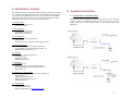
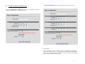
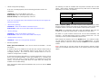
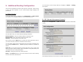
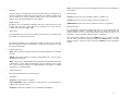
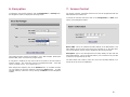
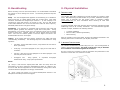
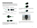
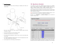
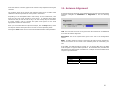
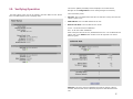
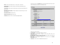
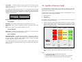
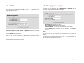
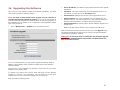
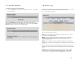
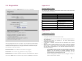
1. Introduction
Congratulations on your purchase of Solectek’s SKYWAY 7000 Series
Bridge/Router Multipoint Client Unit, a feature rich, best-in-class wireless
solution. This User’s Guide will describe the operation of your SKYWAY 7000
unit in detail.
SYSTEM FEATURES
•
•
•
•
•
•
•
•
•
•
•
Field proven OFDM modulation allowing near line-of-sight deployment
and strong immunity to multi-path.
Data rates from 6 Mbps to 108 Mbps.
High power radio (up to 400mW) and improved radio sensitivity for
best in class link ranges.
Power over Ethernet (PoE) for simplified cable routing.
Integrated antenna/radio simplifies installation and eliminates lossy RF
coax runs.
Frame aggregation for enhanced data throughput.
Improved diagnostics and event log.
Line speed QoS packet inspection prioritizes latency sensitive, realtime data.
Line speed AES encryption for the ultimate in security and data
protection.
Spectrum Analyzer mode.
Intuitive Web based user interface.
PACKAGE CONTENTS
SkyWay® 7000 Series
Multipoint Client Unit
User’s Guide
•
•
•
•
•
•
•
SKYWAY 7000 Client Unit.
48VDC Power Supply.
Power over Ethernet (PoE) injector.
Two-axis mast mounting kit.
Ethernet cable weatherproofing feedthrough.
CD-ROM containing documentation and software utilities.
Warranty and Compliance Card.
NOTE: CAT5 Ethernet cables are not included in the package. Please contact
Solectek for information on available UV-protected Ethernet cables for outdoor
use.
Management Platform Requirements
For SkyWay 7100, 7300, and 7500
October, 2005
Version 2.0
a)
For GUI management: Pentium III (or equivalent) computer;
Windows 2000 / XP (or equivalent); Internet Explorer v6.0
b)
For SNMP management: SNMP v1 or v2 compatible SNMP manager,
running on appropriate PC platform.
1
2. Installation Outline
This section summarizes the steps needed to properly configure and install
your Solectek 7000 multipoint Client Unit. As the details and guidelines for
much of the radio installation process are well covered in many in-depth
publications and training classes, only those steps that uniquely relate to
the SkyWay 7000 product are covered in this User Guide.
A. System Design
RF Design and Site Survey
IP Network Design
3. System Connection
A. CONNECTING THE SKYWAY UNIT
Using the appropriate diagram below as a guide (direct to a PC or through
a switch), cable your SkyWay test system. Connect your PC to the POE
injector using (a) crossover Ethernet cable or (b) straight cable and a
hub/switch.
B. Unit Preparation
Unit connection (Section 3)
Configuration (Section 4-7)
Bench testing (Section 8)
C. Site Preparation
Selection of unit mounting location
Cable routing
Preparation of mast and other supporting structures
D. Physical Installation
Mounting of the outdoor equipment (Section 9)
Reconfirmation of spectrum analysis (Section 10)
Antenna alignment (Section 11)
E. Verification
Link status + metrics (Section 12)
Ping connectivity
Performance testing
Reliability monitoring
F. Optimization
RF channel tuning
Data rate tuning (see Product ‘Range Guide’)
Frame Aggregation (feature details in Section 4)
QoS (Section 13)
G. Management + Maintenance
Monitoring link quality and performance (Section 12)
SNMP (Section 14)
Login/Password (Section 15)
Software upgrades (Section 16)
Reboot (Section 17)
H. Troubleshooting
Event Log (Section 18)
Diagnostics (Section 19)
FAQ (see Appendix B and www.solectek.com)
2
B.
CONFIGURE TCP/IP PROPERTIES OF TEST PC (WINDOWS)
Open networking properties in your Windows OS. Find the TCP/IP setup
window of your wired Ethernet adapter. The details on how to set the IP
address of your computer’s Ethernet adapter may depend on Windows version
used. Shown below is the Windows 2000 TCP/IP Properties window. Set the IP
addresses to the following values.
Ethernet’s IP Address:
Subnet Mask:
C. LOG-IN TO YOUR SKYWAY
•
•
Open a Web Browser on the Test PC
At the URL line, type in the following: http://192.168.0.2 to access the
Welcome screen below.
•
Click on the login menu option located in the navy-blue left menu bar.
The following screen should appear:
•
The default username is admin and the default password is default. Once
logged in, the password can be changed. Click OK and you will see the
Main Status screen as shown:
192.168.0.100
255.255.255.0
3
4. Basic Configuration
A. CHOOSING BRIDGING OR ROUTING
The choice between bridging and routing is a key decision that needs to be
made regarding the use of the SkyWay 7000 radio within your network.
Because bridging and routing often require different configuration settings, the
GUI menus will change depending on the mode of operation. To help clarify
these differences, this user’s guide will highlight routing only options in BLUE
and Italic, to emphasize the distinctions.
The navigation toolbar (example shown below) is on the left side of every
screen. Use this navigation toolbar to access different screens of the user
interface.
•
Click the Advanced menu option under the Configuration category on the
Navigator Toolbar to access the System screen as below:
4
Distance to Base: The system adjusts internal parameters according to the
chosen link distance to maximize the data throughput.
Enter the link distance (in miles) to the peer unit, known or expected.
The system default is 10 miles. Be sure that the correct distance is selected for
link distances over 10 miles.
Please note that the actual maximum link distance depends on the radio model
deployed and link conditions. A SkyWay 7000 range guide is available on
Solectek’s web site, www.solectek.com.
Frame Aggregation: Since the overhead associated with the encapsulation
and RF transmission of frames is fixed per packet, the transmission of smaller
frames is less efficient as the overhead takes on a larger percentage of total
traffic.
The SkyWay 7000 unit performs frame packing, which aggregates small frames
into a large one before transmission. This will maximize the overall throughput
of your payload data.
The aggregation system is dynamic in the sense that packing size is also a
factor of link activity and latency considerations.
The default state for frame aggregation is Enabled. You may want to Disable
frame aggregation if your RF link has excessive errors (due to RF interference,
for example). Small packets may have better probability of successful
transmission and you may have an improved link performance.
•
•
Mode of Operation
The user first needs to determine whether the unit will operate in the Bridge or
Router mode. The Bridge mode is the system default option. Be sure to
reboot the unit if you change the mode of operation.
•
RF Output Power
The RF Output Power should be normally kept at the Full value to maintain
the maximum link margin. You may need to choose the -6dB value if the link
distance is very short. The reduction of power can prevent receiver saturation.
NOTE: The 7100 short range client unit has a different menu for the RF Output
Power: High, Medium, and Low.
•
Throughput Optimization
Management Access
VLAN: Your SkyWay 7000 series units will bridge/route VLAN frames
transparently at all times, i.e. all frames tagged with VLAN ID’s will be
recognized and passed though the system. The unit will NOT tag or strip VLAN
ID’s. In this sense, the unit will be transparent to VLAN frames.
The VLAN feature option affects the accessibility of the SkyWay 7000 user
interface by Management computers within a VLAN.
o
Enable/Disable. If access to the Web GUI will be from a PC within a
VLAN, then this feature should be Enabled. If access is from a PC
outside of a VLAN, then this feature should be disabled.
o
VLAN ID: The ID should be set to match the VLAN ID used on your
management PC. This setting does not affect any other VLANs running
on your network or the ability to pass VLAN traffic.
If you have made any changes, click the Update button. Then, navigate to the
Reboot menu option and follow instructions to restart the unit.
5
The Basic Configuration page is slightly different when in Routing mode:
B. IP and Wireless Configuration
Click the Configuration -> Basic menu option on the Navigator Toolbar to
access the following screen if in Bridging mode:
•
System Name
This is a description of the unit used to simplify the identification of a particular
radio in the wireless network. This parameter is not related to the identification
of the unit on your wired local area network. For security purposes, the System
Name is not broadcast across the RF link.
6
•
LAN IP Configuration (Bridging)
If the unit is in Bridging Mode, then the following parameters need to be
configured:
IP Address: This is the IP address of the unit.
Subnet Mask: This is the subnet mask of the unit.
Default Gateway: the default gateway of the unit.
If the unit is in Routing Mode, then both Ethernet and RF ports are assigned IP
addresses as follows:
•
Ethernet Port (Routing)
IP Address: Enter the IP address of the Ethernet port.
Subnet Mask: Enter the correct Subnet Mask of the Ethernet port
•
RF Port (Routing)
IP Address: Enter the IP address of the RF port.
Subnet Mask: Enter the correct Subnet Mask of the RF port
•
Default Gateway (Routing)
IP Address: Enter the correct gateway IP address
•
Wireless properties
Radio Spectrum Bandwidth: There are two choices are available – 20 MHz
and 40 MHz.
If a radio is likely to be installed in an area with other 5.8 GHz radios nearby, it
is best to use the 20 MHz bandwidth setting as this allows for more nonoverlapping channels. This is also the case if multiple radios are to be colocated on a single tower or rooftop.
The following is a table of available radio frequencies and data rates for each
option. (Note that the allowable frequencies may differ from the table below
depending on the country of operation)
20MHz Channel
Frequency (MHz)
Data Rate (Mbps)
40MHz Channel
Frequency (MHz)
Data Rate (Mbps)
5735, 5755, 5775, 5795, 5815,
5835
54, 36, 18, 9, 6
5745, 5785, 5825
108, 72, 36, 18, 12
Radio Frequency (MHz): the center frequency of the selected channel. Note
that the frequency channel you select for the base station is that for the entire
multipoint network. The client unit will operate at this frequency channel.
Data Rate: air transmission data rates. Note that different data rates are
available for 20 MHz and 40 MHz modes, as detailed in the table above.
All radios on a given wireless network must use the same Bandwidth, and
Frequency. The Data Rate setting refers to a Radio’s transmit rate. It is not
necessary to have symmetrical Data Rates across a link.
After changes are complete, click on the Update button. If a mistake is made,
you can restore the previous setting by clicking the Reset button. To make
changes effective, reboot the unit by clicking on Reboot from the Navigation
Toolbar.
NOTE: Clients units do not have choices of radio frequency channels. Clients
units scan the available channels and lock on the frequency channel of the base
station.
If maximizing throughput and distance is of primary importance, then it may be
best to use a 40 MHz bandwidth. At any given datarate (e.g. – 36 Mbps), the
40 MHz setting will attain a longer link distance as compared to the 20 MHz
setting. The 40 MHz setting also allows for higher data rate settings not
available on the 20 MHz setting.
After changing the Radio Spectrum Bandwidth value, be sure to click the Select
button below.
7
5. Additional Routing Configuration
You can find the current routing status by navigating to Status -> Routing
menu option:
There are two mechanisms to build up the system’s route table: Static routing
or RIP. The choice depends on your overall network design topology and
preferences.
A. Static Routing
To activate Static Routing, navigate to the Configuration -> Static Routes
menu option in the navigation toolbar to view the following screen:
B. RIP (Router Information Protocol)
Navigate to the Configuration –> RIP menu option to activate the RIP based
routing
For each static route, you need to add the following information
Network Address – Enter the network address of the static route.
Network Mask – Enter the network mask of the static route.
Gateway – Enter the gateway of the static route.
Once entered, click the Add button to include the newly typed static route to
your static route list (as shown on the bottom of the screen).
You can delete a static route by checking the box to the right of the static route
and clicking the Delete button. Additional grouping functions are available as
follows:
Check All: You can check all boxes by clicking this button. This is usually used
when you want to delete all static routes. Be careful in using this button, as it
could erase all of your routing information.
Clear All: Clicking this button will uncheck all boxes.
Delete - Both Delete buttons on the screen achieve the same result: deleting
all route entries with checked boxes.
The following describes the menu items in the RIP Configuration screen:
8
•
Though typically not implemented across the public Internet, Multicast for IP
support is possible across SkyWay 7000 when RIP v2 is enabled. SkyWay 7000
can be configured to use the multicast address 224.0.0.9 to proliferate route
updates, thus reducing broadcasts of route updates.
•
Expire Time
This field defines how long the route table entries remain in the SkyWay 7000
route table. The default is 180 seconds.
The following describes port configuration related to RIP. Please note that
default configuration fields are identical for the Ethernet and RF ports, but can
be configured differently.
•
•
Receive Mode
Version 1: listens for and will update self with v1 updates only.
Version 2: listens for and will update self with v2 updates only.
Update Interval
By default, every 30 seconds the SkyWay 7000 router will advertise its routes
to other RIP v2 devices. This value can be changed, but it must remain a
multiple of the value for EXPIRE TIME.
•
None: will still listen for and process updates but will not send any updates on
this interface
Multicast
VERSION 1 & 2: listens for and will update self with v1 & v2 updates
•
RIP Default Metric
1: at the default, this SkyWay interface believes it is one hop away from the
nearest gateway interface. Increasing this value by single digit orders this
routing interface to let all other RIP-enabled routers believe that it is a
secondary or higher cost path (typically used for redundancy).
After changes are complete, click on the Update button. If a mistake is made,
you can restore the previous setting by clicking the Reset button. To make
changes effective, reboot the unit by clicking on Reboot from the Navigation
Toolbar.
Authentication Type
Clear: RIP will announce updates and listen for all RIP updates on the specified
interface.
Simple: RIP expects updates to include an authentication key. The key will be
transmitted in clear text.
MD5: per RFC 1321, MD5 Message Digest Algorithm and RFC 2082 RIP-2 MD5
Authentication. Route update authentication keys are entered by user as plain
text. Keys are taken as input by the MD5 algorithm and output as a 128-bit
"fingerprint" or "message digest"
•
Authentication Key
Enter the authentication key for the given port.
•
Send Mode
Version 1: sends only RIP v1 updates.
Ver1 Compatible: sends v2 updates but will listen for v1 (if MULTICAST is
enabled only version 2 is used).
Version 2: sends RIP v2 updates only, no backwards compatibility.
9
6. Encryption
7. Access Control
To manage a unit’s security settings, click on Configuration -> Security from
the Navigation Toolbar to display the following screen.
For security purposes, each base and client unit must be programmed with the
MAC address of its remote unit.
To access the relevant web screen click on the Configuration -> Base menu
option on the Navigation Toolbar.
Base’s MAC: This is the hardware RF MAC address of the Base Station. This
MAC address can be found on the base’s user interface or on the back label.
The correct address must be used to establish an RF link with the base.
Three data encryption options are available: none, AES and WEP. Within both
AES and WEP, there are several key length choices.
If encryption is enabled, the key value must be the same for all units within a
wireless network. Key values are entered in hexadecimal format – each digit
can be a number from 0 - 9 or a letter from a - f.
Description: Type in any description that will easily identify the peer with the
above MAC address. This is an optional field for your convenience only and has
no effect on the operation of the unit.
The base station also needs to have this client unit’s RF MAC address in its
access list for RF link to be established.
After changes are complete, click on the Submit button. If a mistake is made,
you can restore the previous setting by clicking the Reset button. To make
changes effective, reboot the unit by clicking on Reboot from the Navigation
Toolbar.
10
9. Physical Installation
8. Benchtesting
Before mounting units into their final location, it is recommended to benchtest
the system to ensure settings are correct. The following benchtest steps are
suggested:
Setup. The most straightforward approach to benchtesting is to establish a
Point-to-Point link or a Base Station linked with a single Client. Each radio
should be connected and configured per Sections 3 - 5, with a laptop or PC
connected to each radio directly (or through a hub). Be sure that Access
Control MAC addresses are correct and that units share the same frequency,
bandwidth, data rate and encryption settings.
Positioning. It is important to remember that the Skyway 7000 radio and
antenna system generate and transmit a great deal of RF power. During
benchtesting in an average sized room, the antennas should not be pointed
directly at each other. Instead, rotate the unit 90 degrees away from each
other. Fine tune the antenna position so that the Signal Level field in the
Detailed Status Screen is at mid-span.
Testing. If the system has been properly configured, the radios will begin
communicating immediately. The following steps are recommended to verify
operation:
•
Link State. On the Main Status screen, verify that the RF Link State is
Green (connected).
•
Local ping. From each laptop/PC be sure a ping to the local radio is
successful.
•
Link ping. Now ping from one laptop/PC to the other laptop/PC. This
will verify the end-to-end link.
•
Throughput test.
Using Qcheck, or equivalent
measurement utility, verify system performance.
A. INTRODUCTION
Your SkyWay 7000 radio is designed to be mast mounted on a rooftop or radio
tower. After determining the best location for your radio, installation can begin.
Please refer to Solectek’s RF Site Design Guide on Solectek’s website
(www.solectek.com) for more information about choosing an ideal radio
location.
To mount a SkyWay 7000 radio, both the mast mounting kit and Ethernet cable
feedthrough need to be correctly assembled. The recommended approach
consists of 3 steps, detailed in the following sections:
1.
2.
3.
L-bracket installation
Ethernet cable / feedthrough assembly
Mast mounting
With the exception of the CAT5 cable, all parts and hardware described in the
following sections are included with your SkyWay 7000 radio.
B. L-BRACKET INSTALLATION
The L-bracket is fastened to the radio using four 1/4” x 1/2” hex flange bolts as
shown in the following diagram. The mast is shown here only to illustrate
the orientation of the bracket against the enclosure.
Be sure to align the L-bracket so that the orientation and polarization of the
antenna is correct when it is mounted on a mast.
throughput
Notes:
(a) Keep in mind that the Skyway7000 data rates can easily stress the
performance of a poorly performing TCP/IP/Ethernet stack on a laptop or PC.
To ensure that the test equipment is not the bottleneck, testing with a direct
connection between laptops/PCs is strongly recommended.
(b) Using a single FTP session on a typical Windows/Intel machine is not
adequate to accurately measure throughput.
11
C. ETHERNET CABLE / FEEDTHROUGH ASSEMBLY
Only a single Ethernet cable is needed to connect the Skyway radio to the
indoor PoE Injector. Since the cable is exposed to the outdoor elements (heat,
moisture, and UV light), only outdoor rated, shielded Cat5 Ethernet cable
should be used. To ensure all-weather operation, the weatherproofing cable
feedthrough (also known as grommet or gland) must be properly assembled
onto the Ethernet cable and radio.
The following diagram depicts each of the feed-through parts:
The following steps must be followed to make sure that the feedthrough is
assembled correctly:
4.
Slide the Compression Gasket Insert into the Compression Gasket, as
shown above. Make sure to slide the Insert fully, such that the two parts are
evenly aligned.
5.
Install the Compression Nut and hand tighten until the cable resists slipping
when gently pushed or pulled. Lightly wrench-tighten, being careful not to
overtorque the Compression Nut.
The unit with properly installed feedthrough appear as follows:
Note: the total combined length of the Ethernet cables between the radio and
your network access device (hub/switch/PC) must not exceed 300 feet.
1.
2.
3.
Remove the Compression Nut and slip it over the Ethernet CAT5 cable as
shown above.
Slip the Compression Gasket Insert over the Ethernet CAT5 cable
Feed the Ethernet CAT5 Cable through the Feedthrough Body (pre-installed
on the enclosure at the factory) and insert the RJ-45 connector to the female
connector inside the enclosure.
Note: In order to maintain FCC compliance, the use of shielded CAT5 cable is
required.
12
D. MAST MOUNTING
The final installation step involves mounting your SkyWay 7000 radio to an
outdoor mast.
10. Spectrum Analysis
Your SkyWay unit comes with embedded spectrum analysis tool to facilitate
your site survey (NOTE: This feature is available on software version 2.0 or
higher). Spectrum analysis provides valuable information about the RF
congestion in the local area and allows the selection of the ideal channel.
Prior to enabling a spectrum analysis, ensure that the units are mounted at the
desired location and align the antenna in the general direction of the peer radio
before beginning the analysis.
Note: Do not turn on the remote unit during the spectrum analysis, as the
presence of the remote unit will severely distort the sweep data.
Navigate to the Installation -> Spectrum Analysis menu to access the
Spectrum Analysis screen:
1.
Slide the U-bolt around the mast, through the stepped bracket, and then
through the L-bracket.
2.
Insert 3/8” flat washers on to the ends of the U-bolt.
3.
Thread two 3/8” nylock nuts on to U-bolt ends.
4.
For azimuth antenna adjustment, loosen the inner U-bolt nut and rotate radio
around mast.
5.
For elevation adjustments, loosen the outer U-bolt nut and adjust radio so that
the U-bolt leg slides along L-bracket slot.
6.
Wrench tighten both nuts following antenna alignment.
To start the spectrum analysis, click Start button. The unit will scan through
the available channels and display the results on the bottom half of the screen.
Numerical results will indicate the interference levels based on received signals
13
from each channel. The blue graph can be used for easy comparison among the
channels.
The numbers shown to the right of each frequency band are on a relative scale
calibrated in dB and represent the noise power in each band.
Depending on the anticipated nature and severity of local interference, scan
time can vary from a few minutes to a few hours. In extreme cases where
interference may be tied to time of day, a 24 hour sweep may be warranted.
In longer sweeps, refer to average and peak noise figures for the most
appropriate measure of interference.
11. Antenna Alignment
A separate antenna alignment screen facilitates the physical antenna alignment
procedure. Navigate to Installation -> Alignment to see the following
screen:
Once you are finished with the spectrum analysis, click the Stop button, which
will stop the channel sweep and return the unit to normal operating mode.
Clicking the Clear button will zero out all accumulated channel sweep statistics.
Link: The circle will turn from red to green when the wireless link is established
as a result of antenna alignment.
Description: This is the system name given to the unit in the Configuration
screen.
RSSI: A relative measure of power received by the radio currently logged into.
This is the measure of the remote unit’s transmit power as received by your
unit.
At 36 Mbps, the RSSI should be at least 20. For higher data rates, the RSSI
must be higher to support reliable operation. At lower data rates, the RSSI can
fall below 20 and still maintain a reliable link. A sample of minimum RSSI levels
required is provided below:
Minimum RSSI at different data rates
36 Mbps
20
72 Mbps
25
108 Mbps
32
14
This screen updates periodically and thus displays current field values.
Navigate to the Configuration screen if setting changes are necessary.
12. Verifying Operation
The basic status of the unit can be viewed in the Main Status screen. Shown
here is the Main Status screen in bridging mode:
Three noteworthy items:
•
Up Time: This is the elapsed time that the unit has been running since the last
reboot or power cycle.
•
MAC Address: this is the MAC address of the unit.
•
RF Port Link State: The link state has two values.
Green – An RF link has been established
Red – an RF link is NOT established.
Each of the ports also has its own, detailed status screen. For the Ethernet Port
status, click on the details button located on the far right side. The screen
below is typical:
MTU Size: This is the maximum datagram size that the system is able to
transmit. Note that this refers to Ethernet payload not total Ethernet frame
size.
15
The RF Port (click on the details button on the Main Status screen next to each
client’s description) also has its own detailed screen:
State: There are two states, Green – Port Up. Red – Port Down.
Total Frames: total number of frames received and transmitted by the
Ethernet port.
Total Octets: total number of octets (bytes) received and transmitted by the
Ethernet port.
Bandwidth Usage [kbps]: average utilization of the Ethernet port over the
last 5 seconds.
Discarded Frames: PHY layer errors
Unknown Protocols: MAC layer errors
Collisions: MAC layer errors, representing dropped packets.
Fields for this screen include:
•
•
•
•
•
Local RF MAC: The RF port MAC address of the unit.
Local Descr: The description assigned to the unit (client unit) in its
Configuration screen.
Base RF MAC: Indicates the RF port MAC address of the client unit. Recall that
this address must be valid to establish an RF link.
Base Descr: The description assigned to the client unit in the Base’s
Information screen.
Link State: Green if a link is established and Red if not.
16
•
Local RSSI: A relative measure of power received by the radio currently
logged into. This is the measure of the remote unit’s transmit power as
received by your unit.
At 36 Mbps, the RSSI should be at least 20. For higher data rates, the RSSI
must be higher to support reliable operation. At lower data rates, the RSSI can
fall below 20 and still maintain a reliable link. A sample of minimum RSSI levels
needed is provided below:
Minimum RSSI at different data rates
36 Mbps
20
72 Mbps
25
108 Mbps
32
•
Signal Level: A graphical representation of RSSI.
Local Statistics
•
•
•
13. Quality of Service (QoS)
For the transport of real-time data, such as VoIP or streaming video, the
SkyWay 7000 contains a QoS system providing end-to-end prioritization of pretagged Ethernet and IP frames.
The QoS system relies upon the originating network device/appliance to tag
frames using one of the following standards:
a.
b.
c.
802.1p VLAN tag
IP ToS field
IP Diffserv field
As a frame enters the SkyWay 7000, a line speed tag inspection is performed
and frames are prioritized as follows:
a.
Valid Data: Total number of data frames received and sent by the unit.
Valid mgmt: Total number of management frames received and sent by the
unit
Errors: total number of error frames recorded by the unit.
A priority queuing method assigns tagged frames to one of the 4 priority
queues, allowing higher priority data to then be pushed onto the RF stack
ahead of lower priority frames.
Tagged frames are assigned to queues
based on the following tag matrixVoice
Video
Normal
Background
Local Rx Statistics
•
CRC Errors: A wireless PHY layer statistic - specifies the number of frames
rejected at the PHY layer of the radio receive chain.
Local Tx Statistics
•
Discarded Frames: A wireless MAC layer statistic - specifies the number of
frames for which the transmitting radio did not receive acknowledgment from
the receiving radio. There are many possible reasons including an RF path
problem, interference, defective receiver, etc.
Tag Method
The transmitting radio will try twice to send a frame. If both attempts result in
failure, the radio will “discard” the frame and rely on higher layer protocols to
request a retry.
b.
802.1p
0x6
0x7
0x3
0x4
0x5
0x0
0x1
0x2
ToS/Diffserv
0x30
0xe0
0x28
0x88
0xa0
Default
0x08
0x20
Once on the RF stack, the RF MAC gives prioritized frames early access to
the ‘air’ resulting in the frames being delivered sooner to the receiving
radio.
Notes:
•
•
•
The QoS system does not add or alter priority tags
QoS is always ‘enabled.’
For best results, all network devices (switches, routers, gateways)
between source and destination devices should be QoS aware.
17
14. SNMP
The SkyWay 7000 provides support for SNMP v1 and v2. To configure a unit’s
SNMP settings, click on Management -> SNMP from the Navigation Toolbar to
display the following screen:
15. Changing Your Login
To change the unit’s password, click on Management -> Password from the
Navigation Toolbar to display the following screen.
•
•
•
Community Names and Trap Manager IP Address fields should be entered
based on the configuration of your SNMP Manager software.
Click on Update to activate changes.
Please refer to the User Manual of your SNMP Manager software for detailed
information on establishing and managing units via SNMP.
A Solectek custom MIB is available via Solectek’s web site. For further
questions, please contact technical support.
User Name: User selected login name.
Enter New Password: Enter the new password.
Confirm Password: Re-enter the new password for confirmation.
Click the Change button to activate your new password. Click Reset to
start over.
Notes:
(a) Keep in mind that all three fields are case sensitive and no spaces are
allowed.
(b) Please keep this password safe in your records. For your convenience you
can write down the password in Appendix C.
18
16. Upgrading the Software
•
Server IP Address: The address of the computer that stores the upgrade
software file.
There may be newer software releases from Solectek periodically. The latest
version will be posted on Solectek’s website.
•
User Name: User name used to login onto the upgrade FTP server. For
convenience, you may want to use anonymous login.
•
User Password: Password used to login onto the upgrade FTP server.
•
Image File Name: The name of the binary file to be loaded onto your
SKYWAY 7000 unit. This file should have an *.img extension and the full
filename, including extension, should be entered into this field.
•
Image File Directory: Directory path to find the software upgrade file on
the FTP server.
NOTE: You need to install an FTP server program on your computer to
complete the following upgrade procedure. You can use an FTP program of
your choice although Solectek has included FileZilla, an FTP server program, on
the installation CD. For details on the configuration of this application, please
refer to the product CD.
•
Click on Management -> Upgrade to see the following screen:
NOTE: This path name is relative to the root path of the FTP server.
After all information has been entered correctly, click on the Upgrade button.
The upgrade should take less than a minute, and the unit will automatically
reboot once the upgrade is complete.
REMINDER: Do not power down or unplug the unit during the upgrade
process. The updated firmware may become corrupted and the unit
may not operate correctly.
NOTE: On certain upgrades, you may need to upgrade the Bootrom image in
addition to the Firmware. Please consult the release notes of each firmware
release for details.
Verify that the version available from Solectek is newer than the one current
installed on your SkyWay 7000.
To upgrade your system, first copy the latest SW file(s) from the Solectek
website to a local PC. For convenience, you may prefer to use the same
computer that you use to access the SkyWay 7000 user interface.
Next, complete the following fields:
19
17. System Reboot
To reboot the system from the Web Interface:
•
Click on the Reboot menu option on the Navigation Toolbar. The following
screen will appear:
18. Event Log
The Event Log displays all major events that may be noteworthy for the system
administrator for both monitoring and troubleshooting purposes.
The event log appears as follows:
Click on the Reboot button to reset/reboot. The reboot process will take
approximately 30 seconds. Once the rebooting is done, you can use the Click
Here button below to access the user interface again.
There are three categories of events:
INFO: This is informational in monitoring the operation of the unit. The Info
line is part of the normal operation.
WARN: This may indicate something wrong with the unit or operation. For
example, downing of the RF port may be due to malfunction or the user
intervention (power off).
ERROR: This is indicative of abnormal operating conditions. For example, an
error line may be caused by the user typing in unacceptable values in the user
interface.
For easy viewing of specific information that you are looking for, each of the
category (info, warn, and error) can be turned off to give you a more compact
screen.
Verbose: This option adds further detail to each log event and is typically
useful only when working with Solectek technical support. Under normal
circumstances, it is recommended that the Verbose option be disabled.
20
19. Diagnostics
Appendix A
For diagnostics, navigate to Diagnostics menu to view the following:
Factory Default Values
The following table details the factory default values. These are the values that
will be set initially at the factory.
WIRELESS
Radio Spectrum bandwidth
Channel
Transmission Rate
20 MHz
5795 MHz
36 Mbps
LAN
IP Address
Subnet Mask
Login Name / Password
192.168.0.1 for Skyway 7600 or
7800 Base Stations
192.168.0.2 for Skyway 7100, 7300
or 7500 Clients
192.168.0.1 / .2 for Skyway 7101,
7301 or 7501 point to point pairs
255.255.255.0
admin / default
Appendix B
Troubleshooting Guide
1.
“I can’t get a wireless connection between units”
•
Verify that each radio has the correct RF MAC address programmed into its
link configuration.
Verify that both radios are operating on the same Radio Spectrum
Bandwidth and Frequency.
If encryption is enabled, verify that the key information been entered
correctly.
Make sure that the distance between the two radios is within the specified
system range. A quick check of the signal strength and quality indicators
can help assess a marginal RF link. Poor indicator response may be due to
the following reasons:
- Your link distance has exceeded the unit’s capability: Review your
link budget to make sure that the system is able to handle the
distance. Use GPS devices to accurately determine the link
distance first. If you are unsure about the link budget, you may
contact Solectek Technical Support for help.
- Antenna misalignment: antennas must be aligned correctly to
achieve maximum link distance.
•
•
The ping diagnostics tool on the unit can be used to isolate the troubleshooting
event to the wireless link only, not involving other network elements such as
switches and host computers. You can ping the remote unit from the unit you
are accessing via the user interface.
Destination Addr: The IP address of the device to be pinged.
Packet Size: The size of the ping packets to be sent (in bytes).
Packet Count: The number of packets to be sent to the destination IP address.
Click on the Start button to initiate the ping session. Click Stop to terminate it.
•
21
-
Radio interference: The radio activity in the environment is too
strong and may interfere with your signals. You may try to
determine the source by using a spectrum analyzer and a
directional antenna.
2.”I can’t access the SkyWay 7000 over Ethernet from my PC.”
•
•
Make sure the Ethernet connection is properly established.
Make sure that the right IP address is used. Please refer to Section 2:
System Configuration for setting up the right IP addresses for your PC
and SKYWAY 7000 unit.
3. Can’t access the Internet through the SkyWay 7000 unit.
•
•
•
•
First, make sure that the wireless connection is established. Good RF
conditions need to be established between the units’ radios. MAC address
of the other unit needs to be correctly typed in at both the base and client
units.
From a PC on the client unit side, ping the IP address of the SkyWay 7000.
If this does not work, the wireless may still not be properly established or
the LAN IP setting is not correctly set between the SkyWay 7000 and
client.
Ping a known IP address on the Internet, such as Yahoo’s IP address,
66.218.71.81. (From the DOS prompt command line, type “ping
66.218.71.81”). If this does not work, you have a problem getting out to
the Internet. Make sure that the IP setting is set correctly between the
SKYWAY 7000 and the surrounding IP network. Check with your IT
administrator or ISP to see if the Internet connection is up and running.
If you can ping an Internet IP address, but still cannot browse the Internet,
make sure the DNS is set correctly on your network. Check with your IT
administrator or ISP for proper DNS setting for your wireless network.
Information contained in this document is subject to change without
notice. Solectek Corporation shall not be liable for errors contained
herein or for incidental or consequential damage in connection with the
furnishing, performance, or use of this material. Reproduction,
adaptation, or translation without prior written permission is
prohibited, except as allowed under the copyright laws.
Solectek Corporation makes no warranty of any kind with regard to this
material, including, but not limited to, the implied warranties or
merchantability and fitness for a particular purpose.
NOTE: Changes or modifications not expressly approved by Solectek
could void the user’s authority to operate the equipment.
SkyWay and Solectek are registered trademarks of Solectek Corporation.
Windows is the trademark of Microsoft Corp.
Copyright 2005, Solectek Corp. All rights reserved.
Part Number: 1347101
Revision 2.0
Appendix C
For your records please record following items about your unit and keep it safe
in your records:
Username
and
Password:
Encryption
key:
22