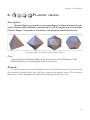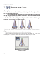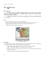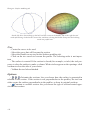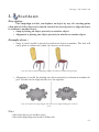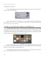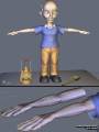
1
Hexagon - Introduction
WELCOME!
Dear user,
First of all, the Eovia team thanks you for your purchase of this program,
Hexagon, our 100% polygon modeler. We have tried to create a powerful product, ergonomic and easy to learn. This program was made with artists for artists.
Any program, even an easy-to-learn one, needs a manual for all the specific
information for each tool and its options. This manual covers each of Hexagon’s functions. We have tried to create a solid and useful manual, with simple and understandable examples for each tool.
You will find throughout this manual videos showing the use of functions, often
more useful than an abstract concept.
A big thank you goes to our beta testers for their work and their remarks, which
helped in the fine tuning of the program. You can find their names and web site addresses at the end of this manual.
Good reading and good modeling!
The Eovia Team
1
Hexagon - Introduction
About this documentation :
Firstly this document is in PDF format, and needs Acrobat Reader® version 7.0
or greater. Another PDF reader (Preview on the Macintosh® for example) will not let
you use this manual to its fullest (playing movies).
You can download Acrobat Reader® from Adobe®’s website here:
http://www.adobe.com/products/acrobat/readstep2.html
In order to illustrate the different explanations presented in this documentation,
we have used videos. Each time you have access to a video an icon for Quicktime®
appears, like this one:
From a technical point of view, they are in Apple Quicktime® format, and require the Quicktime® reader, version 6 minimum. By clicking on these images, the
default video reader on your computer is launched.
You can find Quicktime® to download from Apple®’s website here:
Macintosh : http://www.apple.com/quicktime/download/mac.html
Windows : http://www.apple.com/quicktime/download/win.html
During the playing of the videos, you will see red and blue circles appear. They
symbolize a left click and right click of the mouse, respectively. This way, you know
what click was used.
2
Hexagon - Introduction
The program described in this documentation is furnished under license.
It can only be used or copied in compliance with the terms of this license.
This documentation cannot be reproduced, archived, or transmitted in any way,
except with the pre-approval of Eovia.
This manual is provided for informational purposes only.
It is susceptible to change without notice.
It is not to be considered as a commitment by Eovia, who cannot be held responsible for errors or inaccuracies which might have occurred in the text.
This documentation is written by Laurent Billy, Pascal Doux and Thomas
Roussel, with the help of Andy Beverly for the English translations, Bob Stockwell for
the proof reading, Chrystèle Mercadier for the dubbing.
A big thanks also to: Cedric Trojani, François Rimasson, Gilles Brai, Glen
Southern, Grendel, Hugo Pruvot, Kagi, Marc Thierry, Mike Moir, Moxstudios, Olivier
Draussin, Olivier Drion, Piem, Steph3D and Wayne Kilgore, Yann «Alien» Vaugne..
and to all our beta-testers!
Thank you of course to our developers and the team at Eovia, as well as: Max,
Xavier, Mickael, Pascal, Laurent, Emmanuel, Philippe, Florence, Chrystèle, Stefan, and
Mamie Carmen!
Thomas Roussel
Documentation version 2.1
Copyright © 2005, EOVIA, a DAZ Production Company
Microsoft, Windows, are registered trademarks of Microsoft Corp. Mac OSX and
Macintosh are registered trademarks of Apple Computer Corp.
All other trademarks belong to their respective owners.
3
Hexagon - Table of Contents
Welcome! . . . . . . . . . . . . . . . . . . . . . . . . . . . . . . . . . . . . . . . . . . . . . . . . . 1
II. General Principles and Concepts of
Hexagon . . . . . . . . . . . . . . . . . . . . . . . . . . . . . . . . . . . . . . . . . . . . 16
1. The organization of the workspace . . . . . . . . . . . . . . . . . . . . . . 17
1.1. User Interface Customization . . . . . . . . . . . . . . . . . . . . . . 19
1.2. The Custom Palette . . . . . . . . . . . . . . . . . . . . . . . . . . . . . . . . 20
2. What is a 3D object? . . . . . . . . . . . . . . . . . . . . . . . . . . . . . . . . . . . 21
3. How do you create a 3D model? . . . . . . . . . . . . . . . . . . . . . . . . 23
3.1. Construction . . . . . . . . . . . . . . . . . . . . . . . . . . . . . . . . . . . . . . 23
3.2. Editing. . . . . . . . . . . . . . . . . . . . . . . . . . . . . . . . . . . . . . . . . . . . 23
3.3. Assembly . . . . . . . . . . . . . . . . . . . . . . . . . . . . . . . . . . . . . . . . . 23
4. Hexagon on Mac OS X . . . . . . . . . . . . . . . . . . . . . . . . . . . . . . . . . 24
4.1. Keyboard keys and shortcuts . . . . . . . . . . . . . . . . . . . . . . . 24
4.2. Navigating with the mouse . . . . . . . . . . . . . . . . . . . . . . . . . 24
III. Working in 3D space: Navigation, Working Planes and Guides . . . . . . . . . . . . . . . . . . . . . . 25
1. Navigation . . . . . . . . . . . . . . . . . . . . . . . . . . . . . . . . . . . . . . . . . . . . 26
1.1. Navigation by the Control panel . . . . . . . . . . . . . . . . . . . . 26
1.2. Mouse navigation . . . . . . . . . . . . . . . . . . . . . . . . . . . . . . . . . 27
1.3. Keyboard navigation . . . . . . . . . . . . . . . . . . . . . . . . . . . . . . 27
1.4. Space Mouse Support. . . . . . . . . . . . . . . . . . . . . . . . . . . . . . 28
2. The three working planes . . . . . . . . . . . . . . . . . . . . . . . . . . . . . . . 29
2.1. The absolute working planes . . . . . . . . . . . . . . . . . . . . . . . 29
2.2. The camera working plane . . . . . . . . . . . . . . . . . . . . . . . . . 30
2.3. Specific working planes. . . . . . . . . . . . . . . . . . . . . . . . . . . . 30
3. 3D Guides . . . . . . . . . . . . . . . . . . . . . . . . . . . . . . . . . . . . . . . . . . . . . 31
4. Precise input, relative mode, absolute mode, origins . . . . . 33
4
Hexagon - Table of Contents
IV. How tools function in Hexagon . . . . . . . . . . 34
1. Structure . . . . . . . . . . . . . . . . . . . . . . . . . . . . . . . . . . . . . . . . . . . . . . 35
2. Operation sequence . . . . . . . . . . . . . . . . . . . . . . . . . . . . . . . . . . . . 35
3. Options and accessories . . . . . . . . . . . . . . . . . . . . . . . . . . . . . . . . 37
4. Parameters. . . . . . . . . . . . . . . . . . . . . . . . . . . . . . . . . . . . . . . . . . . . . 37
5. Indication of the tool in use . . . . . . . . . . . . . . . . . . . . . . . . . . . . . 38
V. 3D Manipulator . . . . . . . . . . . . . . . . . . . . . . . . . . . . . . . . . . 40
1. The 3D manipulator . . . . . . . . . . . . . . . . . . . . . . . . . . . . . . . . . . . . 41
1.1.
Translation . . . . . . . . . . . . . . . . . . . . . . . . . . . . . . . . . . . 41
1.2.
Rotation . . . . . . . . . . . . . . . . . . . . . . . . . . . . . . . . . . . . . . 42
1.3.
Scale . . . . . . . . . . . . . . . . . . . . . . . . . . . . . . . . . . . . . . . . . 43
1.4.
Universal . . . . . . . . . . . . . . . . . . . . . . . . . . . . . . . . . . . . . 44
2. 3D Manipulator accessories . . . . . . . . . . . . . . . . . . . . . . . . . . . . 45
2.1. Selection . . . . . . . . . . . . . . . . . . . . . . . . . . . . . . . . . . . . . . . . . . 45
2.2. Working planes and 3D Manipulators . . . . . . . . . . . . . . . 45
2.3.
Hide/Show . . . . . . . . . . . . . . . . . . . . . . . . . . . . . . . . . . . 45
2.4. Delete . . . . . . . . . . . . . . . . . . . . . . . . . . . . . . . . . . . . . . . . . . . . 46
2.5. Dissolve . . . . . . . . . . . . . . . . . . . . . . . . . . . . . . . . . . . . . . . . . . 46
2.6. Copy from the Manipulator . . . . . . . . . . . . . . . . . . . . . . . . 47
2.7. Displaying the Universal Manipulator Components . 47
3. Advanced options for the Manipulators . . . . . . . . . . . . . . . . . . 48
3.1.
Set the pivot . . . . . . . . . . . . . . . . . . . . . . . . . . . . . . . . . . 48
3.2.
Reset the pivot . . . . . . . . . . . . . . . . . . . . . . . . . . . . . . . 49
VI. Selections . . . . . . . . . . . . . . . . . . . . . . . . . . . . . . . . . . . . . . . . . . 50
1. General . . . . . . . . . . . . . . . . . . . . . . . . . . . . . . . . . . . . . . . . . . . . . . . . 51
1.1. Types of selections . . . . . . . . . . . . . . . . . . . . . . . . . . . . . . . . 51
5
Hexagon - Table of Contents
1.2.
Select auto . . . . . . . . . . . . . . . . . . . . . . . . . . . . . . . . . . . 52
1.3. Soft selection . . . . . . . . . . . . . . . . . . . . . . . . . . . . . . . . . . . . . 52
1.4. Selection memorization . . . . . . . . . . . . . . . . . . . . . . . . . . . . 53
2. Selection methods. . . . . . . . . . . . . . . . . . . . . . . . . . . . . . . . . . . . . . 54
2.1. Paint . . . . . . . . . . . . . . . . . . . . . . . . . . . . . . . . . . . . . . . . . . . . 54
2.2. Drag . . . . . . . . . . . . . . . . . . . . . . . . . . . . . . . . . . . . . . . . . . . . 54
2.3. Rectangle lasso . . . . . . . . . . . . . . . . . . . . . . . . . . . . . . . . . . 55
2.4. Polygon Lasso. . . . . . . . . . . . . . . . . . . . . . . . . . . . . . . . . . . 55
3. Selection operations . . . . . . . . . . . . . . . . . . . . . . . . . . . . . . . . . . . . 55
4. Selection accessories . . . . . . . . . . . . . . . . . . . . . . . . . . . . . . . . . . . 56
4.1.
Loop . . . . . . . . . . . . . . . . . . . . . . . . . . . . . . . . . . . . . . . . . . 56
4.2.
Ring . . . . . . . . . . . . . . . . . . . . . . . . . . . . . . . . . . . . . . . . . . 57
4.3.
Select between . . . . . . . . . . . . . . . . . . . . . . . . . . . . . . . . . 57
4.4. One over «N» for Loop, Ring and Select Between. . . 58
4.5.
Grow . . . . . . . . . . . . . . . . . . . . . . . . . . . . . . . . . . . . . . . . . . 59
4.6.
Shrink . . . . . . . . . . . . . . . . . . . . . . . . . . . . . . . . . . . . . . . . . 60
4.7.
Boundary . . . . . . . . . . . . . . . . . . . . . . . . . . . . . . . . . . . . . . 60
4.8.
Convert . . . . . . . . . . . . . . . . . . . . . . . . . . . . . . . . 61
4.9.
1/n . . . . . . . . . . . . . . . . . . . . . . . . . . . . . . . . . . . . . . . . . . . . 62
4.10.
Invert . . . . . . . . . . . . . . . . . . . . . . . . . . . . . . . . . . . . . . . . 62
4.11.
Unselect All . . . . . . . . . . . . . . . . . . . . . . . . . . . . . . . . . . 63
5. Selection Extensions . . . . . . . . . . . . . . . . . . . . . . . . . . . . . . . . . . . 64
5.1. Extend Selection . . . . . . . . . . . . . . . . . . . . . . . . . . . . . . . . . . 64
5.3. Reset Selection . . . . . . . . . . . . . . . . . . . . . . . . . . . . . . . . . . . . 66
5.4. Set Selection Auto Mode. . . . . . . . . . . . . . . . . . . . . . . . . . . 66
5.4. Selection by Topology . . . . . . . . . . . . . . . . . . . . . . . . . . . . . 67
6.
Hide/Show Selected Faces . . . . . . . . . . . . . . . . . . . . . 68
7. Isolate Selection . . . . . . . . . . . . . . . . . . . . . . . . . . . . . . . . . . . . . . . 69
VII. Dynamic Geometry in Hexagon. . . . . . . . 70
1. Modes . . . . . . . . . . . . . . . . . . . . . . . . . . . . . . . . . . . . . . . . . . . . . . . . . 71
6
Hexagon - Table of Contents
2. Dynamic Geometry Tree . . . . . . . . . . . . . . . . . . . . . . . . . . . . . . . 72
3. Controlling the Dynamic Geometry levels . . . . . . . . . . . . . . . 75
3.1. Global control . . . . . . . . . . . . . . . . . . . . . . . . . . . . . . . . . . . . . 75
3.2. Collapsing the Dynamic Geometry . . . . . . . . . . . . . . . 75
3.3. Removing the last dynamic operation . . . . . . . . . . . . . 75
VIII. Modeling with Symmetry . . . . . . . . . . . . . . . 77
1. The Symmetry Mode and the Symmetry Tool . . . . . . . . . . . . 78
1.1. The Symmetry Mode . . . . . . . . . . . . . . . . . . . . . . . . . . . . . . 78
1.2. The Symmetry tool and the Clone function . . . . . . . . . 79
2. Pros and Cons . . . . . . . . . . . . . . . . . . . . . . . . . . . . . . . . . . . . . . . . . 80
IX. 3D Primitives
. . . . . . . . . . . . . . . . . . . . . . . . . . . . . . . . . . . 81
1.
Cube . . . . . . . . . . . . . . . . . . . . . . . . . . . . . . . . . . . . . . . . . . . . . 82
2.
Sphere . . . . . . . . . . . . . . . . . . . . . . . . . . . . . . . . . . . . . . . . . . . . 83
3.
Facet . . . . . . . . . . . . . . . . . . . . . . . . . . . . . . . . . . . . . . . . . . . . . 84
4.
Cone . . . . . . . . . . . . . . . . . . . . . . . . . . . . . . . . . . . . . . . . . . . . . . 85
5.
Cylinder . . . . . . . . . . . . . . . . . . . . . . . . . . . . . . . . . . . . . . . . . . 86
6.
Platonic shapes . . . . . . . . . . . . . . . . . . . . . 87
7.
Grid . . . . . . . . . . . . . . . . . . . . . . . . . . . . . . . . . . . . . . . . . . . . . . 88
8.
3D Text. . . . . . . . . . . . . . . . . . . . . . . . . . . . . . . . . . . . . . . . . . . 89
X. Vertex Modeling . . . . . . . . . . . . . . . . . . . . . . . . . . . . . . . . . 91
1.
Edge Tools . . . . . . . . . . . . . . . . . . . . . . . . . . . . . . . . . . . . . . . . 92
1.1.
Extract Around . . . . . . . . . . . . . . . . . . . . . . . . . . . . . . . 93
1.2.
Extract Along . . . . . . . . . . . . . . . . . . . . . . . . . . . . . . . . . 94
7
Hexagon - Table of Contents
1.3.
8
Fillet . . . . . . . . . . . . . . . . . . . . . . . . . . . . . . . . . . . . . . . . . 95
2.
Fast Extrude . . . . . . . . . . . . . . . . . . . . . . . . . . . . . . . . . . . . . . 97
3.
Move Along . . . . . . . . . . . . . . . . . . . . . . . . . . . . . . . . . . . . . . . 99
4.
Symmetry . . . . . . . . . . . . . . . . . . . . . . . . . . . . . . . . . . . . . . . . 100
5.
Tesselate. . . . . . . . . . . . . . . . . . . . . . . . . . . . . . . . . . . . . . . . . 102
5.1.
Free Tesselate . . . . . . . . . . . . . . . . . . . . . . . . . . . . . . . 102
5.2.
Tesselate by segment . . . . . . . . . . . . . . . . . . . . . . . . 104
5.3.
Add a single vertex on an edge of a polygon . . 105
5.4.
Tesselate by slice . . . . . . . . . . . . . . . . . . . . . . . . . . . . 106
5.5.
Automatic Tesselation . . . . . . . . . . . . . . . 107
6.
Connect . . . . . . . . . . . . . . . . . . . . . . . . . . . . . . . . . . . . . . . . . 108
7.
Smooth more / less . . . . . . . . . . . . . . . . . . . . . . . . . . 110
8.
Close . . . . . . . . . . . . . . . . . . . . . . . . . . . . . . . . . . . . . . . . . . . . 112
9.
Weld objects . . . . . . . . . . . . . . . . . . . . . . . . . . . . . . . . . . . . . 113
10.
Weld points . . . . . . . . . . . . . . . . . . . . . . . . . . . . . . . . . . . . . 114
11.
Average weld . . . . . . . . . . . . . . . . . . . . . . . . . . . . . . . . . . . 116
12.
Target weld . . . . . . . . . . . . . . . . . . . . . . . . . . . . . . . . . . . . . 117
13.
Sweep surface &
14.
Tweak . . . . . . . . . . . . . . . . . . . . . . . . . . . . . . . . . . . . . . . . . . 120
15.
Extract . . . . . . . . . . . . . . . . . . . . . . . . . . . . . . . . . . . . . . . . . 121
16.
Bridge. . . . . . . . . . . . . . . . . . . . . . . . . . . . . . . . . . . . . . . . . . 122
17.
Dissociate . . . . . . . . . . . . . . . . . . . . . . . . . . . . . . . . . . . . . . 124
Extrude surface . . . . . . . . . . 118
Hexagon - Table of Contents
XI. Lines . . . . . . . . . . . . . . . . . . . . . . . . . . . . . . . . . . . . . . . . . . . . . . . . 126
1.
Rectangle . . . . . . . . . . . . . . . . . . . . . . . . . . . . . . . . . . . . . . . . 127
2.
Square . . . . . . . . . . . . . . . . . . . . . . . . . . . . . . . . . . . . . . . . . . . 128
3.
Circle . . . . . . . . . . . . . . . . . . . . . . . . . . . . . . . . . . . . . . . . . . . . 129
3.1.
3.2.
Circle from the center . . . . . . . . . . . . . . . . . . . . . . . . 129
Circle from the basis . . . . . . . . . . . . . . . . . . . . . . . . . 130
3.3.
Circle from diameter . . . . . . . . . . . . . . . . . . . . . . . . . 131
3.4.
Circle from three points . . . . . . . . . . . . . . . . . . . . . . 132
4.
Arc . . . . . . . . . . . . . . . . . . . . . . . . . . . . . . . . . . . . . . . . . . . . . . 133
4.1.
Center – Start/Radius – Angle . . . . . . . . . . . . . . . . 134
4.2.
Start –Center/Radius – Angle . . . . . . . . . . . . . . . . . 134
4.3.
Start – End – Middle . . . . . . . . . . . . . . . . . . . . . . . . . 134
4.4.
Start – End – Center/Radius . . . . . . . . . . . . . . . . . . 135
4.5.
Start – End – Tangent . . . . . . . . . . . . . . . . . . . . . . . . 135
5.
Polyline . . . . . . . . . . . . . . . . . . . . . . . . . . . . . . . . . . . . . . . . . . 136
6.
Bézier . . . . . . . . . . . . . . . . . . . . . . . . . . . . . . . . . . . . . . . . . . . 137
7.
Interpolated Curve . . . . . . . . . . . . . . . . . . . . . . . . . . . . . . . . 139
8.
Curve . . . . . . . . . . . . . . . . . . . . . . . . . . . . . . . . . . . . . . . . . . . . 140
9.
Composite Curves . . . . . . . . . . . . . . . . . . . . . . . . . . . . . . . . 141
10.
2D Text . . . . . . . . . . . . . . . . . . . . . . . . . . . . . . . . . . . . . . . . . 143
11.
Helix . . . . . . . . . . . . . . . . . . . . . . . . . . . . . . . . . . . . . . . . . . . 145
12.
2D Symmetry . . . . . . . . . . . . . . . . . . . . . . . . . . . . . . . . . . . 146
13.
Curve Extraction . . . . . . . . . . . . . . . . . . . . . . . . . . . . . . . . 147
14.
Curve Offset . . . . . . . . . . . . . . . . . . . . . . . . . . . . . . . . . . . . 148
9
Hexagon - Table of Contents
15.
Insert Points . . . . . . . . . . . . . . . . . . . . . . . . . . . . . . . . . . . . 149
16.
Polyline Tesselation . . . . . . . . . . . . . . . . . . . . . . . . . . . . . 150
17.
Close . . . . . . . . . . . . . . . . . . . . . . . . . . . . . . . . . . . . . . . . . . . 151
XII. Surface modeling tab . . . . . . . . . . . . . . . . . . . . . . 153
1.
Ruled surface . . . . . . . . . . . . . . . . . . . . . . . . . . . . . . . . . . . . 154
2.
Double sweep . . . . . . . . . . . . . . . . . . . . . . . . . . . . . . . . . . . 157
3.
Coons surface . . . . . . . . . . . . . . . . . . . . . . . . . . . . . . . . . . . . 160
4.
Gordon surfaces . . . . . . . . . . . . . . . . . . . . . . . . . . . . . . . . . . 162
5.
Extrude line . . . . . . . . . . . . . . . . . . . . . . . . . . . . . . . . . . . . . . 164
6.
Sweep line . . . . . . . . . . . . . . . . . . . . . . . . . . . . . . . . . . . . . . . 167
7.
Boolean operations . . . . . . . . . . . . . . . . . . . . . . . . . . . . . . 171
8.
Thickness . . . . . . . . . . . . . . . . . . . . . . . . . . . . . . . . . . . . . . . 174
9.
Offset . . . . . . . . . . . . . . . . . . . . . . . . . . . . . . . . . . . . . . . . . . . 176
10.
Smoothing . . . . . . . . . . . . . . . . . . . . . . . . . . . . . . . . . . . . . . 178
11.
Chamfer . . . . . . . . . . . . . . . . . . . . . . . . . . . . . . . . . . . . . . . . 181
12.
Weld objects . . . . . . . . . . . . . . . . . . . . . . . . . . . . . . . . . . . . 184
XIII. The Utilities tab . . . . . . . . . . . . . . . . . . . . . . . . . . . . . 186
10
1.
Stretch . . . . . . . . . . . . . . . . . . . . . . . . . . . . . . . . . . . . . . . . . . . 187
2.
Lay on . . . . . . . . . . . . . . . . . . . . . . . . . . . . . . . . . . . . . . . . . . . 189
3.
Snap/Align . . . . . . . . . . . . . . . . . . . . . . . . . . . . . . . . . . . . . . . 191
4.
Taper,
5.
Deformer (NFFD) . . . . . . . . . . . . . . . . . . . . . . . . . . . . . . . . 195
Bender and
Twister . . . . . . . . . . . . . . . 193
Hexagon - Table of Contents
6.
Bend . . . . . . . . . . . . . . . . . . . . . . . . . . . . . . . . . . . . . . . . . . . . . 196
7.
Copy . . . . . . . . . . . . . . . . . . . . . . . . . . . . . . . . . . . . . . . . . . . . 198
8.
Multiple Copies . . . . . . . . . . . . . . . . . . . . . . . . . . . . . . . . . . 199
9.
Copy on a support . . . . . . . . . . . . . . . . . . . . . . . . . . . . . . . . 201
10.
Cut into slices . . . . . . . . . . . . . . . . . . . . . . . . . . . . . . . . . . . 203
11.
Hide . . . . . . . . . . . . . . . . . . . . . . . . . . . . . . . . . . . . . . . . . . . . 205
12.
Show . . . . . . . . . . . . . . . . . . . . . . . . . . . . . . . . . . . . . . . . . . . 207
13.
Group . . . . . . . . . . . . . . . . . . . . . . . . . . . . . . . . . . . . . . . . . . 208
14.
Ungroup . . . . . . . . . . . . . . . . . . . . . . . . . . . . . . . . . . . . . . . . 210
16.
Decimate . . . . . . . . . . . . . . . . . . . . . . . . . . . . . . . . . . . . . . . 213
17.
Extract the openings . . . . . . . . . . . . . . . . . . . . . . . . . . . . . 214
18.
Triangulate non planar facets. . . . . . . . . . . . . . . . . . . . . 215
19.
Triangulate n-gons . . . . . . . . . . . . . . . . . . . . . . . . . . . . . . 215
20.
Merge duplicated points . . . . . . . . . . . . . . . . . . . . . . . . . 216
21.
Merge duplicated UVs . . . . . . . . . . . . . . . . . . . . . . . . . . . 216
22.
Merge coplanar facets . . . . . . . . . . . . . . . . . . . . . . . . . . . 217
XIV. Materials in Hexagon . . . . . . . . . . . . . . . . . . . . . 218
1. Definition . . . . . . . . . . . . . . . . . . . . . . . . . . . . . . . . . . . . . . . . . . . . 219
2. Materials Palette . . . . . . . . . . . . . . . . . . . . . . . . . . . . . . . . . . . . . . 219
3. Materials Management . . . . . . . . . . . . . . . . . . . . . . . . . . . . . . . . 221
3.1. Creating a new material . . . . . . . . . . . . . . . . . . . . . . . . . . . 221
3.2. Operations on Materials . . . . . . . . . . . . . . . . . . . . . . . . . . 222
4. Shading Domains . . . . . . . . . . . . . . . . . . . . . . . . . . . . . . . . . . . . . 222
4.1. Creating a Shading Domain on a Selection of Faces 222
4.2. Operations on Domains . . . . . . . . . . . . . . . . . . . . . . . . . . . 224
11
Hexagon - Table of Contents
XV. Creating and Managing UVs . . . . . . . . . . . 225
1. Texture mapping . . . . . . . . . . . . . . . . . . . . . . . . . . . . . . . . . . . . . . 226
1.1. Using the Gizmos . . . . . . . . . . . . . . . . . . . . . . . . . . . . . . . . 226
1.2. The Gizmo Editor . . . . . . . . . . . . . . . . . . . . . . . . . . . . . . . . 228
1.3. The Gizmo UV Stretch . . . . . . . . . . . . . . . . . . . . . . . . . . . 228
2. The UV editor . . . . . . . . . . . . . . . . . . . . . . . . . . . . . . . . . . . . . . . . 229
2.1. Interface . . . . . . . . . . . . . . . . . . . . . . . . . . . . . . . . . . . . . . . . . 229
2.2. Selection and Manipulators . . . . . . . . . . . . . . . . . . . . . . . 231
2.3. Tools working with UVs . . . . . . . . . . . . . . . . . . . . . . . . . . 231
2.4. Options and Utilities . . . . . . . . . . . . . . . . . . . . . . . . . . . . . . 232
3. Unfold . . . . . . . . . . . . . . . . . . . . . . . . . . . . . . . . . . . . . . . . . . . . . . . 233
3.1. Principles . . . . . . . . . . . . . . . . . . . . . . . . . . . . . . . . . . . . . . . . 233
3.2.
Unfolding UVs . . . . . . . . . . . . . . . . . . . . . . . . . . . . . . 234
3.3.
Re-editing the Unfolding . . . . . . . . . . . . . . . . . . . . . 235
XVI. Surface displacement Modeling . . . . . 237
1. Concepts . . . . . . . . . . . . . . . . . . . . . . . . . . . . . . . . . . . . . . . . . . . . . 238
1.1. Structure, Mesh Density and Smoothing . . . . . . . . . . . 238
1.2. From the Rough Shape to the Detailed One . . . . . . . . 239
1.3. True or Fake Modeling? . . . . . . . . . . . . . . . . . . . . . . . . . . 239
1.4. Preparing the 3D Model Before Displacement Modeling
240
1.5. Multi-resolution smoothing . . . . . . . . . . . . . . . . . . . . . . . 241
2. Communication with other 3D tools. . . . . . . . . . . . . . . . . . . . 242
2.1. Exporting Geometry . . . . . . . . . . . . . . . . . . . . . . . . . . . . . . 242
2.2. Displacement Texture Export . . . . . . . . . . . . . . . . . . . . . 243
2.3. Bump Map Texture Export . . . . . . . . . . . . . . . . . . . . . . . . 244
2.4. Bump Map and Displacement Texture Export . . . . . . 245
12
Hexagon - Table of Contents
XVII. Brushes and Painting . . . . . . . . . . . . . . . . . . . 246
1. Principles of the Displacement and Painting Tools . . . . . . 247
1.1. The Working Channels . . . . . . . . . . . . . . . . . . . . . . . . . . . 247
1.2. Revealing Textures to Paint or to Displace . . . . . . . . . 248
1.3. Brush Shapes . . . . . . . . . . . . . . . . . . . . . . . . . . . . . . . . . . . . 249
1.4. Load Your Own Brushes or Textures to Reveal . . . . . 250
1.5. Brushes Display . . . . . . . . . . . . . . . . . . . . . . . . . . . . . . . . . . 251
1.6. Types of Strokes. . . . . . . . . . . . . . . . . . . . . . . . . . . . . . . . . . 252
1.7. Working with the Graphic Tablet . . . . . . . . . . . . . . . . . . 252
1.8. Working with Symmetry . . . . . . . . . . . . . . . . . . . . . . . . . . 253
2. Using Displacement and Painting Tools . . . . . . . . . . . . . . . . 254
2.1.
Displacement Brush. . . . . . . . . . . . . . . . . . . . . . . . . . 254
2.2.
Soften . . . . . . . . . . . . . . . . . . . . . . . . . . . . . . . . . . . . . . . 256
2.3.
Pinch . . . . . . . . . . . . . . . . . . . . . . . . . . . . . . . . . . . . . . . . 258
2.4.
Inflate . . . . . . . . . . . . . . . . . . . . . . . . . . . . . . . . . . . . . . . 259
2.5.
Paint . . . . . . . . . . . . . . . . . . . . . . . . . . . . . . . . . . . . . . . . 261
2.6.
Brush . . . . . . . . . . . . . . . . . . . . . . . . . . . . . . . . . . . . . . . 263
3. Exporting Textures . . . . . . . . . . . . . . . . . . . . . . . . . . . . . . . . . . . . 266
3.1. Color and Transparency Textures . . . . . . . . . . . . . . . . . . 266
3.2. Bump Textures . . . . . . . . . . . . . . . . . . . . . . . . . . . . . . . . . . . 267
3.3.
Displacement Maps . . . . . . . . . . . . . . . . . . . . . . . . . . 268
XIV. The control panel . . . . . . . . . . . . . . . . . . . . . . . . . . . 270
1. Presentation . . . . . . . . . . . . . . . . . . . . . . . . . . . . . . . . . . . . . . . . . . 271
2. Organization of 3D workspace: split views . . . . . . . . . . . . . 271
3. Snapping and axis constraints: 3D guides . . . . . . . . . . . . . . 272
4. Centering Tools . . . . . . . . . . . . . . . . . . . . . . . . . . . . . . . . . . . . . . 273
4. 3D navigation tools . . . . . . . . . . . . . . . . . . . . . . . . . . . . . . . . . . . 274
5. 3D drawing styles . . . . . . . . . . . . . . . . . . . . . . . . . . . . . . . . . . . . 275
13
Hexagon - Table of Contents
6. Real-time Display . . . . . . . . . . . . . . . . . . . . . . . . . . . . . . . . . . . . . 276
6.1.
Lightmaps . . . . . . . . . . . . . . . . . . . . . . . . . . . . . . . . . . . . 276
6.2.
Real-time Shadows . . . . . . . . . . . . . . . . . . . . . . . . . . . 276
6.3.
Ambiant Occlusion. . . . . . . . . . . . . . . . . . . . . . . . . . . . 277
XV. The Scene properties palette . . . . . . . . . . . . 279
1. The Scene tree tab . . . . . . . . . . . . . . . . . . . . . . . . . . . . . . . . . . . . 280
2. The Scene properties tab . . . . . . . . . . . . . . . . . . . . . . . . . . . . . . 281
XVI. The Object properties palette . . . . . . . . . 282
XVIII. Preferences . . . . . . . . . . . . . . . . . . . . . . . . . . . . . . . . . 286
1. The Interface preferences . . . . . . . . . . . . . . . . . . . . . . . . . . . . . . 287
1.1. General . . . . . . . . . . . . . . . . . . . . . . . . . . . . . . . . . . . . . . . . . 287
1.2. Grids . . . . . . . . . . . . . . . . . . . . . . . . . . . . . . . . . . . . . . . . . . . . 287
1.3. 3D Rulers . . . . . . . . . . . . . . . . . . . . . . . . . . . . . . . . . . . . . . . . 288
1.4. Misc . . . . . . . . . . . . . . . . . . . . . . . . . . . . . . . . . . . . . . . . . . . . . 288
2. Display preferences . . . . . . . . . . . . . . . . . . . . . . . . . . . . . . . . . . . 289
2.1. Entities display . . . . . . . . . . . . . . . . . . . . . . . . . . . . . . . . . . . 289
2.2. Selection . . . . . . . . . . . . . . . . . . . . . . . . . . . . . . . . . . . . . . . . . 289
2.3. Advanced display parameters . . . . . . . . . . . . . . . . . . . . . 290
2.4. Lighting parameters . . . . . . . . . . . . . . . . . . . . . . . . . . . . . . 290
3. Import/Export options . . . . . . . . . . . . . . . . . . . . . . . . . . . . . . . . . 291
XIX. Imports / Exports . . . . . . . . . . . . . . . . . . . . . . . . . . 292
Enjoy . . . . . . . . . . . . . . . . . . . . . . . . . . . . . . . . . . . . . . . . . . . . . . . . . . . . . 295
14
© HUGO PRUVOT - HEXAGON - CINEMA4D
[email protected]
Hexagon - General Principles and Concepts of Hexagon
II. GENERAL PRINCIPLES
AND CONCEPTS OF
HEXAGON
Hexagon is a program for creating models in 3D. It will help you create and
model structures, smooth or solid, starting by drawing its contours, inner or outer, or
by starting with a simple structure, which you will extend, deform and refine to create
before you what is in your imagination.
You are going to create your models in a window representing a 3 dimensional
space, and by using a number of tools, or functions, go from simple forms to more complex, following your own tastes. You will be able to edit, observe, and come back to edit
again, to your heart’s content, until you reach your goal. Finally, you can prepare your
models to be textured, ready to export to another program to fully texture, animate and
render a final 3D image with special effects.
16
Hexagon - General Principles and Concepts of Hexagon
1. THE ORGANIZATION OF THE WORKSPACE
Hexagon and its interface.
The workspace of Hexagon is divided into eight zones:
• The 3D workspace in which you can build and visualize your 3D models.
• The Manipulators palette gives you choices over how you want to position your
models in the 3D workspace: moving, rotating, scaling, etc.
• The Selection palette contains tools for selecting all or parts of your 3D scene
and models.
• The Modeling palette contains all the tools for building and editing your models, organized for a logical workflow from 2D to 3D.
• The Properties panel contains information about the scene. The Object properties palette has information about your scene and objects, with precise measure17
Hexagon - General Principles and Concepts of Hexagon
ments and input of positions and dimensions. The Tool properties palette gives
you options specific for each tool and creation of objects. The Scene properties
palette also shows you the structure of your scene, and gives you access to your
models. The Dynamic Geometry palette lets you control and edit your objects’
history, letting you fine tune to get the final result you want.
• The Control Panel gives access to the principal functions of view, display,
navigation, and the style of how your 3D objects are represented in the 3D
Workspace.
• The Materials panel contains the Materials properties and domain properties
palettes, giving you control over how you texture your model.
• The Contextual Menu, which provides direct access to various options and accessories, and whose content depends on the type of element on which it is
activated (by default right-click). The Contextual Menu is available on a 3D
object and on Manipulators.
The Hexagon contextual panel
18
Hexagon - General Principles and Concepts of Hexagon
1.1. USER INTERFACE CUSTOMIZATION
It is possible to customize the Hexagon 2 user interface in order to organize it
according to the specific needs of your current creation.
You can detach palettes which are located in the side panels, resize them, reorganize them, or even lay them out on two columns.
Click and drag the palette to detach it. Move the palette window where you want
on the screen, or on a second screen. To re-attach the palette in a side panel, move the
palette on the top, bottom, or side until you see a blue line which indicates the location
the palette will be placed in when the mouse button is released.
To minimize a palette, click on the down-arrow icon, located on the right of the
title bar. To maximize a palette, click again on the down-arrow icon.
To close the palette, click on the X icon. The palette will disappear. To make it
visible again, select it from the Window pull-down general menu.
Watch the video!
Remark:
- If needed, you can reset all User Interface Preferences, by selecting in the File
menu, under User Resources, the “Reset Interface” command.
19
Hexagon - General Principles and Concepts of Hexagon
1.2. THE CUSTOM PALETTE
In addition to the default palette layout, Hexagon 2 provides a custom palette,
which allows you to create your own collection of the most used tools. To add a tool
in the custom palette, right-click on its icon. To remove a tool from the custom palette,
right-click in the custom palette on the tool’s icon. In both cases, a dialog box will ask
you to confirm the operation.
The first palette icon lets you detach the palette from the tab. A click on the
triangle of the title bar of the palette opens a small pull-down menu, which allows you
to close or to switch the orientation of the custom palette.
The Custom Palette in floating mode.
20
Hexagon - General Principles and Concepts of Hexagon
2. WHAT IS A 3D OBJECT?
A 3D Object is made of points in space, creating faces, or facets, between those
points. The faces are polygons in space, which are represented on screen in perspective
with colors and textures, in order to give an illusion of a real object.
The 3D basic elements, from left to right: Faces, vertices and edges.
The sides of faces are called edges. The points that make up the faces are also
called vertices.
A 3D Object is made up of faces, combined together in various complexity,
which can be open (surface) or closed (volume).
It is important to note that, when modeling with polygons, an object can appear
curved or rounded, but is always composed of few or many faces, each having a slight
angle, giving the illusion of curvature.
Another type of 3D element you will be working with are called curves, or lines,
or are also sometimes referred to as polylines.
These are made up of points, connected by segments, but with no face. These are
structures, like a framework you will be wrapping in fabric to make up a 3D object.
21
Hexagon - General Principles and Concepts of Hexagon
Curves components: points, segments, and eventually control points and control curves.
Lines are the basis of construction, letting you create sections and profiles and
elevations, and later as a guide in 3D space for “attaching” faces.
Curves used as construction curves.
22
Hexagon - General Principles and Concepts of Hexagon
3. HOW DO YOU CREATE A 3D MODEL?
The creation of a 3D model consists of construction, editing and, eventually,
assembling the element with one or more other 3D objects.
3.1. CONSTRUCTION
You can construct an object using these three principal methods:
ject.
• By using what is called 3D Primitives: generic predefined objects such as a
cube, sphere and cone.
• By drawing several lines and combining them together, such as a circle and
profile becoming a vase.
By modeling each polygon, one by one, until they make up your desired ob-
In practice, you will be combining these 3 methods, depending on the complexity of the model.
3.2. EDITING
Since an object is rarely made perfect on the first try, you will need to verify and
edit the object and its exact position in space.
For this, you will be using certain editing functions (tools) in taking your model
from start to finish. The simplest edits might be moving a point/vertex in space to finetune its position. More advanced editing could be subtracting geometric volumes from
each other.
3.3. ASSEMBLY
Depending on the scene you want to create, you might need to bring several
objects together. For example, it might be necessary to put an object representing part
of the model in an exact position, and then combine it with another form.
23
Hexagon - General Principles and Concepts of Hexagon
4. HEXAGON ON MAC OS X
Most of the actions, tools and way of use are exactly the same on both Mac OS
X and Windows. There are, however, some slight differences which are important to
know.
4.1. KEYBOARD KEYS AND SHORTCUTS
To perform a keyboard shortcut, the usual combination is “CTRL+ key”. On
Mac OS X, the Control/CTRL key is replaced by the Command (Apple) key.
In this manual, when you will read a shortcut written as “CTRL + key”, this will
mean that on Mac OS X you have to perform “Command + key”.
Except this difference regarding the keyboard, all other key actions and combinations are identical.
4.2. NAVIGATING WITH THE MOUSE
Historically, mice provided with Macintosh computers have been one-button
mice, until the “Mighty Mouse” has been released by Apple, with several buttons and
a mouse wheel.
Hexagon 2 has been designed to use utilize a 3-button mouse with wheel (including the Mighty Mouse), both for 3D navigation, using the contextual menu, and
more.
If your system has a one-button mouse, please note that the “Right Click” is
performed by the holding the “CTRL + Click” on your keyboard. Furthermore, we recommend that you to get a 3-button mouse (a good quality optical mouse with 3 buttons
can be found for very little cost), for a more efficient workflow and more comfort (not
only with Hexagon 2!).
24
Hexagon - Working in 3D space
III. WORKING IN 3D
SPACE: NAVIGATION,
WORKING PLANES AND
GUIDES
You will be working in a three dimensional space (XYZ). Your mouse is a two
dimensional pointing system and your computer screen can only show a flat image, so
Hexagon proposes different ways of working within these limits.
25
Hexagon - Working in 3D space
1. NAVIGATION
Navigation is the movements of the virtual point of view, or camera, around
the scene. When you want to inspect your model from all angles or zoom in, you will
need to navigate in your 3D space.
Hexagon offers three ways to navigate: by the icons in the Control panel, by
the mouse and by the keyboard
1.1. NAVIGATION BY THE CONTROL PANEL
In the Control panel at the bottom of your workspace, you will find two groups
of icons which deal with navigation:
- Use the
icon to turn your camera around the target point.
- Use the
icon to pan around the scene, or displace laterally (such as camera
traveling in film terminology).
- Use the
icon to zoom in and out.
Holding down the mouse button on an icon navigates directly on the icon, or
click on an icon, turning your mouse cursor into that icon, and navigate directly in the
3D Workspace by click-dragging and return to 3D manipulation by clicking on the
icon.
- Use the
« View all » repositions your camera, without changing its orientation,
so that all the elements in the scene are visible
- Use the
« View selection » repositions your camera so that the selection is
visible.
- Use the
« View detail» lets you draw with a red rectangle selector to specify
the area to include in the new placement of the camera.
- Use the
« Custom View » to point the camera at an element by clicking in the
3D Workspace, or by inputting coordinates in the Tool properties palette. You can also
use the tool option Place eye in the same palette, to specify interactively or by precise
input, where you want to place your camera. Once you have placed your target point, or
the virtual eye, Validate the tool to continue working.
26
Hexagon - Working in 3D space
1.2. MOUSE NAVIGATION
- While holding down the Alt key, click-drag with the left mouse button in the 3D
Workspace to rotate the camera around the scene (like the
icon)
- While holding down the Alt key, click-drag with the middle mouse button in the 3D
Workspace to zoom the camera in and out (like the
icon)
- While holding down the Alt key, click-drag with the right mouse button in the 3D
Workspace to pan around the scene (like the
icon)
Additional mouse navigation commands:
- Use the mouse wheel to zoom in and out step-by-step (like the icon ).
- Click and hold the mouse wheel button to pan around the scene (like the icon
).
Remarks:
- The mouse wheel zoom target is defined by the on-screen mouse cursor, while
Alt key and middle mouse button will zoom in and out toward the center of the 3D
Workspace.
- Combine the shortcuts Alt + CTRL and the left mouse button to rotate the camera
around the current selection (object, vertices, edges or faces). You can choose the mode
as default by changing the preference “Dolly Around Selection”, in the “User Interface”
tab, under section “Misc”.
1.3. KEYBOARD NAVIGATION
- The Arrow keys turn the camera in the direction of the keys.
- The Arrow keys with the Alt key pressed will pan the camera in the direction of
the keys.
- On the number keypad, use the ‘3’ key to zoom in and the ‘.’ key (Period key) to
zoom out
- Finally use the ‘2’, ‘4’, ‘6’, ‘8’ keys to directly view the scene from the front, left,
right and back respectively. The keys ‘5’ and ‘9’ are the bottom and top views, respectively.
Watch the video!
27
Hexagon - Working in 3D space
1.4. SPACE MOUSE SUPPORT
3Dconnexion motion controllers allow you to navigate more efficiently in the
3D scene while modeling.
These devices have a single controller that transforms your movements into
camera movements.
There are several types of motion controllers from 3Dconnexion: SpaceMouse,
SpaceBall, SpaceTraveler, Cadman, SpacePilot, and more. They are all based on the
same architecture and use the same device driver, which is supported by Hexagon 2.
Installation:
- Install the software provided with the 3Dconnexion motion controller and test it with
the provided tools. If needed, you can download the drivers at http://www.3dconnexion.
com.
- Once you have installed the 3Dconnexion software, you will be able to use the
device with Hexagon.
- You must first enable the device in the preference panel, located in the User
Interface/Misc tab.
Camera movements:
The possible camera movements are:
- Pan left and right: move controller left and right.
- Pan up and down: pull controller up and down.
- Zoom in and out: push controller forward or pull backward.
- Rotate left and right: twist controller clockwise or counterclockwise.
- Rotate up and down: tilt controller forward and backward.
28
Hexagon - Working in 3D space
2. THE THREE WORKING PLANES
To work in 3D space (to draw a profile, move an object) the proposed
method used by most 3D programs is to work always on one plane in 3D space.
2.1. THE ABSOLUTE WORKING PLANES
The three reference grid guides
By default, Hexagon lets you work in the so-called absolute planes, symbolized
in the 3D Workspace by three reference grid guides. The horizontal plane (XZ), the
vertical plane (XY) and the transversal plane (YZ).
The axis indicator on the lower left of the 3D Workspace is the 3D trihedron.
When you move around the 3D space, you can see that the active working plane is symbolized by a white square touching two of the axes. By default, Hexagon automatically
chooses the best working plane for your view, or the one that is the most perpendicular
to the camera position.
The 3D trihedron
You can force Hexagon to make another working plane active that is not automatically proposed, by clicking on the faces of the 3D trihedron to work in that plane.
Click again on that same face to return to automatic mode.
29
Hexagon - Working in 3D space
2.2. THE CAMERA WORKING PLANE
You also might not want to work with the default XYZ planes, but with what is
called the Camera plane. This can be compared to having a piece of paper that is always
held out in front of you, turning as you change your view, always staying perpendicular
to your field of view.
The Default and Camera planes switch button
Activate this plane by clicking on the Camera button on the Manipulators palette. Come back to the three absolute working planes by clicking on the XYZ button.
2.3. SPECIFIC WORKING PLANES
In some cases you may want to work on a plane defined by the face of an object
(the side of a pyramid for example) in order to manipulate an element on this plane or
perpendicular to it.
Usage:
- Click on the « Custom plane enabled »
button on the Manipulators sub-palette.
- Click on a face of the object corresponding to the plane you want to work in.
Hexagon changes the working plane to match it.
- Click on the « Reset the working planes »
button to come back to the default
planes.
This functions:
- Either by “flipping” the grid guide representing the working plane
,
- or by giving the impression of “flipping” the scene, with the grid guide staying the
same
These two actions have the same result, and you can choose whichever you are
most comfortable with.
When you have no further use for the Custom working planes, reset the planes
to the default, so that further created objects will not be created in an unwanted orientation.
The working planes are taken into account when lines and forms are created,
or certain tools are used. The 3D manipulators is an exception. If the manipulators
are on Selection or Bbox mode, these planes are ignored. See the chapter on the 3D
30
Hexagon - Working in 3D space
Manipulators for more details.
3. 3D GUIDES
The three modes of the 3D Manipulators
in the Sub palette
The 3D Guides while drawing a Polyline.
Hexagon uses in some cases 3D guides (two perpendicular axes)
,
that can also show incremental measurements. They permit you to work precisely with
distance measurements within certain tools. They also let you restrict your work to one
axis only.
These 3D guides are in the active working plane automatically when using certain tools. If your camera is facing your object, Hexagon shows you only the X axis
(horizontal, in red) and the Y axis (vertical, in green) and you can apply constraints to
one axis by using the Space bar.
The incremental measurement snap to the 3D guides can be activated by clicking on the
icon in the Control panel. When the snap is active, the lines snap to each
unit or tenth of a unit, depending on the measurement unit chosen.
To increase or decrease the units, use the +/- keys.
31
Hexagon - Working in 3D space
Watch the video!
The last used axis constraint of the 3D guides will continue to apply to current
and future tools. Using the Space bar, you can flip the constraint again to the other plane,
or again to have no constraints on your cursor (the default mode).
It is important to keep in mind the fact that the Space Bar will allow you to apply vertical or horizontal constraints while using a tool which uses 3D Rulers, such as
Drawing tools or Snap/Align or the Symmetry tool.
32
Hexagon - Working in 3D space
4. PRECISE INPUT,
MODE, ORIGINS
RELATIVE MODE, ABSOLUTE
Hexagon is a program which can work without constraints in a freehand style,
but can as well use precise number input, or parameters, for the majority of the tools.
By default, Hexagon works in Relative mode: all new values are defined by the
previously entered values. For certain uses, it is necessary to define an origin to your 3D
universe, which is by default in the center of the horizontal grid guide, and inputting a
value in reference to this point is referred to as Absolute mode.
Changing from Relative mode to Absolute mode:
• In the Scene properties palette, a Relative/Absolute icon lets you choose the
mode of measurements feedback and input values.
Remark:
- The center of the universe can be changed from the Preference panel in the Interface
tab, Rulers parameters.
33
Hexagon - How tools function in Hexagon
IV. HOW TOOLS FUNCTION
IN HEXAGON
A tool is a function of the program that can create, manipulate or modify an
object or part of an object.
Tools are organized in six major tool palettes, or Tabs, and some of them, corresponding to advanced or less often used functions, are accessible in the sub-palette of
the corresponding Tool Tab (see Chapter II-1: The Organization of the Workspace).
Tools are accessible by clicking on the respective icon in the appropriate Tools
palette or by selecting its name from the Tools menu, or by using its keyboard shortcut.
34
Hexagon - How tools function in Hexagon
1. STRUCTURE
Each tool has:
• An operation sequence or order of steps.
• Eventual options and accessories.
• The capability to enter precise numbers.
2. OPERATION SEQUENCE
The idea of an operation sequence is important:
• Certain tools have an immediate effect, so their sequence of operations is only a
single step. For example, increasing the smoothing of an object takes only one
click on the smoothing icon.
• Certain tools have a number of fixed steps. For example, creating a cube has
two steps: define its starting point, and then its dimension.
• Most tools have any number of steps and it is the user that decides when to
stop. For example, drawing a polyline: the creation of each point of the polyline
is a step in the operation sequence, but the number of points you can create is
infinite! In this case, you need to Validate the tool, or finish its operation by
validating its action.
•
•
•
•
You can validate a tool with any of the following four methods:
By clicking on the Validate button on the Tool properties palette.
By using the Enter key, which is the keyboard shortcut for the Validate button.
By selecting another tool: the action in progress is then validated.
By selecting a 3D Manipulator.
35
Hexagon - How tools function in Hexagon
The Validate and Abort buttons.
You can also cancel the use of a tool, thereby canceling all the steps already taken, by clicking the “abort” button in the Tool properties palette, or by using the Escape
key on the keyboard.
For example, if you are in the middle of drawing a polyline, canceling will make
the line disappear. If you are in the middle of extruding a face of an object, canceling
will cause it to revert to its initial stage.
36
Hexagon - How tools function in Hexagon
3. OPTIONS AND ACCESSORIES
The Extrude and Sweep tool’s options
A tool can do complex operations. The operations can have variations, which
are accessible by the tool’s options. These are symbolized by icons in the Tool properties palette.
The options can vary depending on the step of the operation sequence you are
at.
4. PARAMETERS
The Sphere parameters.
A tool produces geometric actions of construction and editing. These actions
are most often made in an interactive fashion in the 3D workspace with the help of your
mouse cursor. Hexagon also offers complete control by entering exact numbers for all
tool actions. This permits you, for example, to create a box of precise dimensions or set
an exact thickness.
This precise control is made possible by the input of parameters of tool actions
in progress. When you use a tool, the parameter values follow the position of your
mouse cursor in the 3D workspace.
Click in the parameters input zone. The field is now open for editing and you
can input numbers using the keyboard. You can validate your entry either by using the
Enter key, or by clicking the « Validate » button.
37
Hexagon - How tools function in Hexagon
You can also use the wheel of your mouse, once the field is open for editing,
and the values will increase or decrease one at a time following the movement of the
wheel.
5. INDICATION OF THE TOOL IN USE
in use.
38
When you select a tool, its icon and name show up confirming for you the tool
© PATRICK TUTEN
TUTENGRAPHICS.COM
Hexagon - 3D Manipulator
V. 3D MANIPULATOR
Polygon modeling is essentially based on the manipulation of 3D entities such
as points, edges and faces, whether it is for the creation or editing of surfaces or volumes.
Hexagon is based a 3D Manipulator which lets you make 90 % freeform models
(organic forms without precision, for example) without ever leaving the manipulator to
change tools, views, etc.
These 3D Manipulators offer incorporated accessories, which can be either be
called up at any time by keyboard shortcuts, or by selecting corresponding icons.
40
Hexagon - 3D Manipulator
1. THE 3D MANIPULATOR
1.1.
TRANSLATION
This manipulator moves the selected elements. The manipulator is symbolized by arrow points (2D and 3D).
• If you click on an axis, the movement of the selected item is restricted to that
axis.
• If you click on a triangle on the same plane as the two axis , the movement is
restricted to that plane.
The Translation Manipulator.
Keyboard shortcut: T
41
Hexagon - 3D Manipulator
1.2.
ROTATION
This manipulator rotates the selected elements. The manipulator is symbolized by circles.
• If you click on a circle corresponding to an axis, the rotation of the selected
element is limited to that axis.
The Rotation Manipulator.
Keyboard shortcut: R
42
Hexagon - 3D Manipulator
1.3.
SCALE
This manipulator scales the selected elements. The manipulator is symbolized by cubes.
• If you click on a cube on the end of an axis, the scaling of the selected element
is limited to that axis.
• If you click on one of the grey cubes on the same plane as the two axes , the
scaling is restricted to that plane.
This manipulator also shows a global interactive box which surrounds the
object.
• Click on a face of this box to scale the object as if you were pulling on the
face.
• Click on an edge of this box to pull on both faces that touch that edge.
• Click on a corner of the box to scale the box proportionally away from the
opposite corner.
The Scale Manipulator
Keyboard shortcut: S
Watch the video!
43
Hexagon - 3D Manipulator
1.4.
UNIVERSAL
This manipulator is a combination of the three fundamental manipulators.
It lets you perform moves, rotations and scalings without changing the tool.
Using this manipulator is practical to move the objects globally. However for
precise manipulations of 3D entities like vertices or edges, the number of clickable modifiers on each axis may become a problem.
The Universal Manipulator.
Remark :
Watch the video!
- The size of the manipulator is modifiable in the preferences.
Keyboard shortcut: U
44
Hexagon - 3D Manipulator
2. 3D MANIPULATOR ACCESSORIES
2.1. SELECTION
The 3D manipulators and their accessories work according to the current selection. For example, if you are in Select Point mode, and you use the Translation manipulator to move an edge, it will affect only the selected edges and not the other entities.
2.2. WORKING PLANES AND 3D MANIPULATORS
The working plane can be defined for the manipulators in the conext menu
located on the current manipulator:
• World: According to the working planes defined globally in the program, e.g.:
the three absolute planes XYZ, the camera plane or the specific plane.
• Selection: The working axis snaps to the internal orientation of the selected
element (the geometric normal of the face or edge selected).
• Bbox: The working axis of the manipulator follows the orientation of the object’s bounding box. If the object is rotated, the axis lets you scale or move it
using its own axis.
2.3.
HIDE/SHOW
This function lets you hide the manipulator when necessary, like when making complex selections around the clickable areas of the manipulator.
• Click the
tors.
icon in the Manipulators palette to hide or show the manipula-
Keyboard shortcut: Space bar
45
Hexagon - 3D Manipulator
2.4. DELETE
Lets you delete the selected 3D entity.
This function is available only by the Edit menu or by pressing the Delete key.
Watch the video!
2.5. DISSOLVE
key
Lets you delete a selected entity, but reconstruct the geometry around it.
This function works on Select points, Select edges and Select faces mode.
This function is available only by the Edit menu or by pressing the «Backspace»
Watch the video!
46
Hexagon - 3D Manipulator
2.6. COPY FROM THE MANIPULATOR
In Object selection mode, when holding the CTRL key (Command on Macintosh)
while moving, rotating or scaling, the transformation is applied to a copy of the original
object. This allows you to speed up simple copy operations.
Remark:
- This operation does not work on curves because CTRL key (Command on
Macintosh) with the manipulators is a shortcut of the Fast Extrude tool, and as such it
will generate an edge extrusion.
2.7. DISPLAYING THE UNIVERSAL MANIPULATOR COMPONENTS
The Universal Manipulator has numerous components, displayed in a small
screen area. According to the point of view, it will sometimes be that case that theses
components can hinder visibility, especially when a Manipulator axis is oriented toward
the camera. In this case, these components will be grayed and could not be selected.
When the camera will move around, the grayed components will be reactivated
as previously.
On the left, the grayed components and on the right, after a camera
modification, the components are back.
47
Hexagon - 3D Manipulator
3. ADVANCED OPTIONS FOR THE MANIPULATORS
3.1.
SET THE PIVOT
The Pivot is the center reference point of the selected object. Rotation and scale
manipulators use this point as the center of rotation or the point of reference for scaling.
This accessory lets you temporarily redefine the pivot as a position other than
the default, or define the position by modes of semi-automatic placement such as
«Selection», «World» and «Bounding Box».
Use:
- Click on the Set Pivot function in the Context Menu over the Manipulator.
- Define the new pivot position by clicking in the scene on a point already existing
on any object in the scene.
- The pivot of the selected object is placed at the chosen point.
Notes:
- The new position of the pivot isn’t visible if there is no selection active on the
object.
- The position is only applied to the currently selected object. The pivots of the other
objects are not affected.
48
Hexagon - 3D Manipulator
3.2.
RESET THE PIVOT
This accessory lets you reset the pivot of an object if it had its pivot modified.
Use:
- Select the object to have its pivot reset.
- Click the Reset the pivot function in the Context Menu over the Manipulator.
- Hexagon replaces the pivot to its original place
Watch the video!
49
Hexagon - Selections
VI. SELECTIONS
Hexagon software’s modeling tools vary according to the type of object selected.
Certain tools work with edges and not faces, where other tools adapt their behavior to
the chosen selection mode. Therefore, it is important to choose the right selection mode
before you choose a tool.
50
Hexagon - Selections
1. GENERAL
The complete Selection palette.
1.1. TYPES OF SELECTIONS
There are four types of selections:
•
•
•
Vertices (or Points): the basis of all 3D construction.
Edges: made up of at least 2 points.
Faces: made up of at least 3 edges, with no maximum.
Object: several faces making up a surface, or segments making up a line.
Selection modes, as the name implies, select only certain elements:
• In select point mode, you can affect only points.
• In select edge mode, you can affect only an edge (and the two points that make
it up).
• In select face mode, you can affect only a face (including the edges and points
that make it up).
• In select object mode, you affect the whole object.
The same tool, Move or Translate for example, can have very different results,
depending on whether you want to retouch a detail (move a point on the object) or make
a bigger change such as an assemblage (moving the whole object in the scene).
To change from one mode to another, just click on the icon for the mode you
want in the Selection palette at the top of the screen between the Manipulators palette
and the Modeling tools palette.
51
Hexagon - Selections
1.2.
SELECT AUTO
Select auto is a fifth mode that lets you work in all the modes without having to
use the keyboard shortcuts or clicking on the other mode’s icons. The first item selected
on the object becomes the selection mode by default (facets, for example), until you
deselect everything. A single click in the 3D workspace (next to your object, for example) turns the mode back to select auto. A double-click in the 3D workspace changes the
mode to select object.
You can also double-click on another object, thereby passing on select auto
mode for that object
Watch the video!
1.3. SOFT SELECTION
The soft selection in action.
Complementing the selection modes, there is a specific option that smoothly increases the influence of a manipulation around the active selection: the “Soft
Selection”.
For example, on a face, select a polygon corresponding to a part of the cheek.
52
Hexagon - Selections
With no Soft Selection, if you move the selected polygon, it will be the only element
moving. Activate the Smooth Selection, and an influence area will appear around the
selected element, represented by red points (maximum influence) whose color becomes
black (minimum influence). Move it now, you will see that a part of the nose is modified
as well, smoothly following your manipulation.
Two parameters and one option, in the Tool Properties Panel, will allow you to
fine-tune this Soft Selection:
- Radius: defines the size of the influenced area around the selection.
- Softness: the influence ratio in the soft selection area. The higher the value, the less
flexible the modified surface.
- Freeze: Allows you to keep the same influence area around the selection after the
modification.
Note:
Watch the video!
The Soft Selection only works with the 3D Manipulator (Move, Rotate, Scale,
Universal) and within the Tweak tool.
Keyboard shortcut:
CTRL+SHIFT+mouse click&drag to change the radius.
1.4. SELECTION MEMORIZATION
Note that the active selection is memorized if you leave one mode for another
(unless you are in auto select mode). For example, while working in select point mode
you have five points selected, and you change to select face mode. Hexagon hides the
selected points while you work with the faces, until you reselect the select point mode.
Hexagon then hides the faces you selected until you again return to select face mode.
It is not possible to work in several modes at once, such as with faces and
points.
53
Hexagon - Selections
2. SELECTION METHODS
The following modes can create selections in different ways: they work with
points, edges and faces selection tools.
2.1. PAINT
This mode lets you draw a selection by clicking and dragging the cursor over the
form, like a brush on an object, leaving behind it the selected elements. Any click on the
object outside the selection deselects the existing selection and starts a new one.
menu.
The default mode for the left click of the mouse is available in the selection
Watch the video!
2.2. DRAG
This mode lets you move the selection according to the last movement made by
the manipulator, without even clicking on it. Hexagon software keeps in memory the
last operation and applies it to the new element when you click and drag. This is very
practical for making fast changes and fine tuning.
mode.
When dragging over unselected items, it selects these items like it does in paint
Alternative mode for the mouse left click, which can be used by clicking the
Drag icon in the Selection palette.
54
Hexagon - Selections
2.3. RECTANGLE LASSO
This mode lets you make a selection with a rectangular lasso. Frame the elements to select with a click and drag of the mouse. When the mouse button is released,
all the items within the rectangle are selected.
menu.
The default mode for the right click of the mouse is available in the selection
When using the rectangular lasso, the Shift key adds, and the CTRL key subtracts from the selection.
However, you must first launch the Rectangle Lasso tool before pressing the
mofidier key (Ctrl or Shift).
2.4. POLYGON LASSO
This mode lets you make a selection with a polygon drawn around the elements
in a series of clicks. Finish your lasso selection by hitting the Enter key, or click on the
Validate button in the Tool Properties palette.
The alternative mode for the right click of the mouse is available by clicking on
the button drag lasso icon in the selection menu.
When using the polygon lasso, the Shift key adds and the CTRL key subtracts
from the selection.
However, you must first launch the Polygon Lasso tool before pressing the mofidier key (Ctrl or Shift).
3. SELECTION OPERATIONS
Hexagon has basic operations like adding or subtracting an element from the
selection.
These operations are accessed with the Shift key, which switches back and forth
depending on the selection:
• Shift + Click a selected item to deselect it.
• Shift + Click a non selected item to add it to the existing selection.
55
Hexagon - Selections
4. SELECTION ACCESSORIES
Hexagon software has several accessories which make selecting easy and
save time. It is important to remember their respective keyboard shortcuts to have
quick access during modeling, although their functions are accessible by icons in
the Selection palette.
4.1.
LOOP
The Loop tool lets you expand a selection along a surface by continuing it as
far as possible in the direction you started. In the case that a Loop cannot be completed,
Hexagon automatically stops at the problem zone to keep a mistake from being made,
for example where several connected faces split into a Y intersection.
The Loop tool works with faces and edges, but not with points.
When working in Select Faces mode, if only one face is selected the Loop tool
selects one direction and shows the result. Clicking once again on the Loop tool will
show the other possible selection. To determine a direction, you must have at least two
faces selected to specify the direction to expand the selection.
Use:
- Select an edge one or two faces to start.
- Click on the Loop icon in the Selection palette.
- Hexagon finishes the selection for you.
Keyboard shortcut: L
56
Watch the video!
Hexagon - Selections
4.2.
RING
The «Ring» tool lets you expand a selection along a surface by continuing it as
far as possible in the direction you started, as with the Loop tool, but in parallel, like the
rungs on a ladder. In the case that a Ring cannot be completed, Hexagon automatically
stops at the problem zone in order to not make a mistake, for example at the tip of a
triangle.
The Ring tool works only on edges.
Use:
- Select an edge to start.
- Click on the icon Ring, in the Selection palette.
- Hexagon selects all the edges parallel to this edge.
Keyboard shortcut: K
4.3.
Watch the video!
SELECT BETWEEN
The «Select between» tool lets you connect a selection on a surface after defining its start and finish. The tool only works on simple cases, like a direct path. Since
this tool is based on Loop and Ring, it will stop at the same types of problems which
would stop those other tools.
The Select between tool works with faces and edges but not with points.
Use:
- Select edges or faces to mark the beginning and end.
- Click on the icon Select between, in the Selection palette.
57
Hexagon - Selections
- Hexagon adds to the selection all the edges or faces found between your indicated
start and finish.
Note:
- If the Select between tool gives no result, it is because there was no result possible, such as the start and finish selection were not aligned on the surface (in the same
loop/ring).
Keyboard shortcut: J
Watch the video!
4.4. ONE OVER «N» FOR LOOP, RING AND SELECT BETWEEN
- After extending the selection with the Loop, Ring and Select Between tools, it is
possible to set the selection step to select One over “N” elements in the loop.
- This feature allows you, for example, to have one entity selected over 3 along a
loop, which will help you in doing specific operations, and avoid having to do complex
selection operations.
Use:
- In edge or face mode, do a Loop, Ring or Select Between selection.
- In the Tool Property Panel, set the value for the selection over “n” and the offset
value.
- In the 3D workspace, the updated selection appears.
- Choosing another tool or clicking on the object or 3D workspace will make these
options disappear.
58
Hexagon - Selections
Watch the video!
4.5.
GROW
The Grow tool lets you expand the active selection, and works with faces, edges
and points.
Use
- Make a selection
- In the Selection sub-palette, click in the « + » icon
- In the Selection menu, or in the Contextual Menu, then trough the Advanced
Selection sub-menu, choose “Grow”.
Watch the video!
59
Hexagon - Selections
4.6.
SHRINK
The Shrink tool lets you reduce the active selection, and works with faces, edges
and points.
Use
- Make a selection
- In the Selection menu, or in the Contextual Menu, then trough the Advanced
Selection sub-menu, choose “Shrink”.
- Hexagon subtracts from the selection all elements on the outer limits of the selection.
Watch the video!
4.7.
BOUNDARY
The Boundary tool lets you select the edges around a previously selected face.
Use
- Make a selection of touching faces.
- In the Selection menu, or in the Contextual Menu, then trough the Advanced
Selection sub-menu, choose “Boundary”.
- Hexagon selects all edges around the previously selected faces, and goes into Select
edges mode, thereby deselecting the previously selected faces.
60
Hexagon - Selections
Keyboard shortcut: B
4.8.
Watch the video!
CONVERT
The Convert tool lets you change one type of selection into another. For example, a selection of faces can be converted into a selection of edges or points. The selection mode changes automatically depending on the conversion.
Use
- Make a selection.
- Use the appropriate “Convert” tool, located in the Selection menu, or in the
Contextual Menu, sub-menu Advanced Selection.
- Hexagon converts automatically the selection
Watch the video!
61
Hexagon - Selections
4.9.
1/N
The «1/n» tool lets you make a selection of alternate entities on an object, such
as one point out of two or one point out of three.
Use
- Select your object and choose a selection mode.
- In the Selection menu, or in the Contextual Menu, then trough the Advanced
Selection sub-menu, choose “1/n ”.
- In the Tool Properties palette, input a value to divide by (more that 1).
- Hexagon automatically makes the selection.
- Validate the tool to keep the selection.
4.10.
INVERT
The Invert tool lets you invert your selection on an object, and works with faces,
edges and points.
Invert
- Make a selection.
- In the Selection menu, or in the Contextual Menu, then trough the Advanced
Selection sub-menu, choose “Invert”.
- Hexagon inverses the selection, or all the non-selected elements become selected
and the original selection is deselected.
Watch the video!
62
Hexagon - Selections
4.11.
UNSELECT ALL
The «Unselect all» command lets you cancel any current selection.
Use
- In the Selection menu, or in the Contextual Menu, then trough the Advanced
Selection sub-menu, choose “Unselect All”.
- Hexagon automatically cancels the selection.
63
Hexagon - Selections
5. SELECTION EXTENSIONS
The Selection is an important concept in Hexagon. It is used intensively,
and to maximize productivity some functions are accessible through specific shortcuts and/or mouse manipulations. These functions will save time while modeling,
as well as will providing extra features which will allow you to perform advanced
selections with ease.
5.1. EXTEND SELECTION
This function allows you to extend an existing edge or faces selection along the
topology of the current object.
Use:
- Select edges or faces.
- While holding both the CTRL (Command on Macintosh) and Shift keys, click-drag
the mouse over the object: a blue line appears showing the direction of the extension.
Change the direction of the extension by moving your cursor to a different area.
Example of use:
- Once a “1 over N” Loop selection is performed, it is easy to make stripes of selections over the model.
Remark:
- This tool being based on the topological structure of the objects, it may happen that
some unexpected results occur, especially when the extension encounters a significant
change in the topology, such as for example a Y intersection.
Shortcut:
CTRL/Command+Shift+Right click while draging the mouse.
64
Hexagon - Selections
5.2. SHIFT SELECTION
This function allows you to move an edge or face selection over the object
topology.
Its use is similar to the Extend Selection tool previously described.
Use:
- Select edges or faces.
- While holding the CTRL-Key (Command-key on Macintosh), click-drag the mouse over the object: a blue line appears showing the direction of the extension. Change
the direction of the extension by moving your cursor to a different area.
Shortcut:
CTRL/Command+click while draging the mouse.
65
Hexagon - Selections
5.3. RESET SELECTION
This is not really a tool. Rather, this action, triggered by a double-click, enables
the user to clear the active selection, according to the current selection mode, which
avoids in some cases having to click in an empty area of the 3D scene.
In some cases, when the user camera is very close to an object and when the
screen is covered by the geometry of the model, clearing the selection with a simple
double-click avoids the need to zoom out, click in the empty space, and zoom in again.
Use:
- With some edges, vertices, or faces selected, double-click on the current object to
clear all selections.
5.4. SET SELECTION AUTO MODE
This function is a quick way to activate the Selection Auto Mode (Hyperlink)
when the current selection mode is set to Vertex, Edge or Face, without having to click
on the corresponding icon in the Selection panel.
Use:
- If the current Selection Mode is Vertex, Edge or Face, and if there is an active selection, double-click on the current object or click outside to clear the selection.
- Double-click on the object to activate the Auto Mode.
Remark:
- If the current selection mode is Vertex, Edge or Face, and if there is an active selection, you can set the Auto Mode back by doing two subsequent double-clicks.
66
Hexagon - Selections
5.4. SELECTION BY TOPOLOGY
This set of functions enables you to perform selection according to the topology
of the objects. They are useful to identify potential mesh structure issues (for example,
unseen triangles in a mesh which you want to be perfectly quadrangular), or to validate
a model before exporting it to another software product that does not support any kind of
topology (for example, software that does not handle faces with more than 4 points).
The following options are available under the “Selection” pull-down menu:
• Select faces with more than 4 points.
• Select Triangles. Useful to detect triangles that could eventually cause troubles
with smoothing, etc.
• Select non-quadrangular faces.
• Select non-planar faces: allows you to detect ”twisted” faces that can create
unexpected visual effects at rendering time.
• Select non manifold edges: select edges sharing more than two polygons.
• Select points sharing more or less than 4 edges: enables you to detect potential
unwanted topology structures.
Use:
- Select the object you want to apply the specific selection on.
- Call the appropriate selection command, either in the Selections pull-down menu,
or through the contextual menu, in the Advanced Selection section.
Watch the video!
67
Hexagon - Selections
6.
HIDE/SHOW SELECTED FACES
It is often necessary to temporarily hide some faces of an object when working on smaller or internal details. Three icons located in the control panel allow
you to hide the selected faces, to reveal hidden facets of the currently selected object, or to reveal all hidden faces.
Objects having hidden faces have a small icon near their name in the scene
tree.
Use:
- To hide a list of faces: Select the group of faces to hide. Then click on the Hide
selected faces icon from the control panel ( ).
- To reveal the hidden faces on an object: select the object and click on the Show
hidden faces icon from the control panel ( ).You can also click on the Show hidden
faces icon from the Scene tree dialog near the object’s name.
- To reveal the hidden faces on all objects: click on the Show hidden faces icon from
the control panel ( ).
Remarks:
- Selecting entities on an object with hidden faces will not affect the hidden vertices,
edges or faces. For example, a Loop selection will only include the edges displayed on
the screen, not the invisible ones.
- Subsequently, all operations performed will not affect masked polygons. However,
global operations such as moving, rotating, smoothing objects, will affect all polygons,
even the masked ones.
Watch the video!
68
Hexagon - Selections
7. ISOLATE SELECTION
When there are numerous objects in the scene, it is sometimes difficult to
navigate the scene or to work on a specific object. The “Isolate Selection” function
temporarily masks all the objects in the scene except the selected one, making a
more comfortable working environment.
Use:
- Select the object to isolate.
- In the Selection pull-down menu, choose “Isolate Selection”.
- All unselected objects disappear from the scene.
- To have the whole scene displayed again, just click again on “Isolate Selection” in
the menu. The hidden objects will reappear immediately.
Remark:
- “Isolate Selection” does not make the objects invisible like the “Mask” tool does.
So using the “Unmask” tool will not make the objects hidden by the “Isolate Selection”
function visible.
Watch the video!
Shortcut: CTRL/Command+Shift+I
69
Hexagon - Dynamic Geometry
VII. DYNAMIC GEOMETRY
IN HEXAGON
Dynamic Geometry (DG) permits Hexagon to memorize all the construction
steps of an object, giving you the ability to change an earlier step and update automatically (dynamic) all the following steps to recreate the finished form (geometry).
70
Hexagon - Dynamic Geometry
1. MODES
The Dynamic Geometry palette.
This is a very powerful concept, which can also make modeling more complex
because the form is more abstract and is recalculated.
Hexagon gives you the choice of working with three levels of Dynamic
Geometry that are appropriate to the object you are modeling, balancing the tradeoff
between power and simplicity.
You can choose one of the following levels of Dynamic Geometry :
• No GD: no Dynamic Geometry means no steps are memorized.
Only smoothing remains dynamic.
• Restricted DG: Only the steps of surface construction are memorized. You can
then modify dynamically all the sections and profiles that construct a surface.
However, any operations that modify the objects (face extrusion, thickness,
chamfer, Booleans) will collapse the existing construction DG.
• Full DG: All steps of construction are memorized and are dynamically modifiable. You have complete access to the construction tree (or history) of your
object.
71
Hexagon - Dynamic Geometry
2. DYNAMIC GEOMETRY TREE
The Dynamic Geometry palette shows and gives access to what is called the
Construction Tree, or Dynamic Geometry Tree, of the selected object.
This tree is a symbolic representation of the steps taken to model an object, giving access to the different elements that you have combined to create the final object.
Select for example, Full DG, then create a circle and extrude it:
The Dynamic Geometry palette shows:
• Form0 : The extruded object, resembling a tube
• Curve0 (control): The original circle
• Curve1 (control): The profile generated from the extrusion
This means that “Form0” has two composites which are the circle and the profile of the extrusion.
In the Dynamic Geometry Tree, select the object Curve1. To have a better view
in the 3D workspace, select “activate the transparent display of subsections” icon in the
control panel.
You have selected the curve that is the profile of the tube object. In Select Points
mode, use the Translate manipulator on the points of the profile.
The points are moving following your cursor, and the final object is reconstructed dynamically in real time!
72
Hexagon - Dynamic Geometry
Choose Select object mode.
Now add a thickness to the tube.
In the DG Tree, an extra level has been added :
•
•
•
•
Form1 : The object with a thickness
Form0 : The object that was extruded
Curve0 (control) : The original circle
Curve1 (control) : The profile generated from the extrusion
You can now again edit the points of the profile Curve1 as before and the object
rebuilds in real time, with its thickness.
You can now apply a smoothing to your object:
. In the DG Tree, again another level has been added (Form2), symbolizing the
new operation producing the smoothed tube... and you can always go back and select
the first steps in the construction of the tube
73
Hexagon - Dynamic Geometry
You can also select the thickened object (Form1) in the DG Tree, and edit the
value of the thickness in the Tool Properties palette.
The thickness changes and the smoothing is automatically recalculated dynamically, with all the previous steps still conserved.
Note: You can also access the parameters of each step by first selecting the
level in the DG Tree, then you can click on the icon of the tool used which appears in
the Object Properties palette. This brings up the original options in the Tool Properties
palette.
Watch the video!
All these possibilities are equally effective for more complex operations, such
as a using one volume to cut into another (Boolean operations) where an adjustment of
the scale or position of one volume is updated instantly on the final shape.
The power of Dynamic Geometry offered by Hexagon permits the fine-tuning
of each step and parameter of construction, even after the model is well advanced.
Obviously, conserving all the steps of construction can mean that editing an
early step can use a lot of computer resources, reducing the interactivity, as well as
consuming more memory
74
Hexagon - Dynamic Geometry
3. CONTROLLING
VELS
THE
DYNAMIC GEOMETRY
LE-
3.1. GLOBAL CONTROL
As described above, to better control this powerful tool Hexagon proposes to
either work without DG, only keep the DG for the creation of surfaces, and of course
keeping the full DG history.
3.2. COLLAPSING THE DYNAMIC GEOMETRY
It is also possible to collapse the DG. This operation means that you can flatten
all or only part of the DG Tree. Hexagon will forget the steps for the levels which you
no longer are able to edit later.
To do this, use the icon which is next to each level of the DG Tree. Click on
the
icon at the level you want to become the new base of the Tree.
On clicking on the
icon a the highest level, you collapse the entire tree,
including the smoothing, making the points, edges and faces available for individual
editing.
3.3. REMOVING THE LAST DYNAMIC OPERATION
Inversely, you can also remove the last dynamic operation applied to the object
by clicking on the
icon in the DG Tree, at the highest level of the tree. Attention: this
is not the same as the Undo command. This action removes all the steps as well as the
last step of construction on the object.
This remove operation can itself be cancelled by using “Undo”.
75
© CÉDRIC TROJANI - HEXAGON - CARRARA
WWW.GRAPHINC.COM
Hexagon - Modeling with Symmetry
VIII. MODELING WITH
SYMMETRY
Many 3D models are symmetrical, such a car, a character, and more. To make
the modeling process easier, Hexagon provides two ways to work in symmetry, each of
them having its own advantages. ”Modeling with symmetry” simply means that when
you perform any operation on a model (such as moving vertices, extruding faces, and
more), this operation is automatically applied in real time on the symmetrical part of
the model, and in a symmetrical way (moving a vertex to the right will move the symmetrical vertex to the left, and so on).
77
Hexagon - Modeling with Symmetry
1. THE SYMMETRY MODE
TOOL
AND THE
SYMMETRY
It is important to note that, to model with symmetry, Hexagon provides a symmetry mode and a symmetry tool. The difference is essential: in the mode case the
current object is updated, while in the tool case a new object is created.
1.1. THE SYMMETRY MODE
This mode, available in the object Properties Panel, allows you to choose a
symmetry plane, based on the X, Y or Z axis.
The Symmetry parameters in the Object Property Panel
Of course, this function works only if the object is already totally or partially
symmetrical, a small tolerance value being applied. This plane is represented by a green
rectangle. If the object is largely asymmetrical, this function will be deactivated.
If the object is symmetrical only on one plane, the symmetry is activated only
on that plane. In case of an object having several symmetrical planes, if the plane activated by default is not the one you want just switch to the desired one by clicking in the
X, Y or Z icons.
The Symmetry Mode can be deactivated at any time, turning the displayed
Symmetry plane from green to grey. This can be useful to perform a specific operation
that you do not want to be applied symmetrically. You will then be able to reactivate it,
with Hexagon memorizing the symmetry plane.
Remark:
- The symmetry axis is based on the object axis, and not the world axis
78
Hexagon - Modeling with Symmetry
Watch the video!
1.2. THE SYMMETRY TOOL AND THE CLONE FUNCTION
The Symmetry tool options and the Clone feature.
Contrary to the Symmetry Mode, the Symmetry Tool allows you to create a
copy of the current object, according to a plane specified within the tool, and eventually
with an offset.
By default, the symmetry tool creates a new object which is independent of the
initial one. This means that when you perform an operation on the original model, this
operation is not automatically applied to the mirror copy.
If you want to automatically apply changes to the mirror copy, a “Clone” option is available when creating the symmetrical object, allowing you to create a true
mirror copy: any modification on one of the two mirrored object will be applied on the
other one, up until the “clone” property is suppressed (either by welding the two parts
together, or by suppressing this dynamic property through the Dynamic Geometry panel).
Watch the vidéo!
79
Hexagon - Modeling with Symmetry
2. PROS AND CONS
The two above capabilities share numerous similarities, but are very different.
Below is a list of the respective pros and cons of the Mode and the Tool:
• The Symmetry Mode allows you to modify vertices which are located on the
symmetry plane, since they are constrained to it. The Symmetry Tool does not
apply any geometric constraint.
• The Symmetry Mode allows you to create asymmetrical objects, and enables
you to model locally with symmetry, which is not allowed by the Symmetry
Tool.
• Some tools do not work with the Symmetry Mode, in which case you will need
to manually apply the operation on both halves of the model. This is not the case
with the cloned mirror copy, which works with all tools.
• Using a cloned mirror copy allows you to quickly mask and unmask half the
model. In the Symmetry Mode, you need to select half of the geometry and then
use the mask function on this selection.
80
Hexagon - 3D Primitives
IX. 3D PRIMITIVES
3D Primitives are objects created by Hexagon to serve as a basis of modeling:
whether creating simple or complex objects, these forms can serve as a good starting
point. However, keep in mind once these forms are created, they are no longer editable
in the sense of changing the parameters that are available at their creation.
For example, once the creation of a primitive sphere is validated, the amount of
tessellation can no longer be edited. Nevertheless, these shapes could still be affected
by other tools, such a smoothing.
81
Hexagon - 3D Primitives
1.
CUBE
Left : a perfect Cube. Right : a 3D parallepiped
Use:
- Select the Cube tool in the 3D Primitives Tab.
- Click in the 3D workspace to create the cube, or by entering its coordinates in the
Object properties palette. If necessary, in the Tool properties palette choose create from
Center and not by Basis (the default).
- Move the mouse to define the size of the cube and validate the tool, or enter the
dimensions in the Tool properties palette.
- One the cube has been created, hit the +/- keys to tessellate the cube, or manually
enter the tessellation level in the Tool properties palette.
Remark:
- It is also possible to drag-and-drop the tool icon into the 3D scene, which will create
the primitive located where you will have released the mouse button. The Primitive
dimensions will be automatically defined according to the 3D View size.
82
Hexagon - 3D Primitives
2.
SPHERE
The different kinds of Spheres
Use:
- Select the Sphere tool in the 3D Primitives Tab.
- Click in the 3D workspace to create the sphere, or by entering its coordinates in the
Object properties palette. If necessary, in the Tool properties palette choose create from
Center and not by Basis (the default).
- Move the mouse to define the size of the sphere and validate the tool, or enter the
dimensions in the Tool properties palette.
- In the Tool properties palette, define the number of points that make up a half
diameter of the sphere, as well as the vertical/horizontal pucker and bloat (an in/out
distortion around the hemisphere or vertical axis).
Option :
-
Pole-sphere (default)
Geodesic Sphere.
Geodesic Sphere based on an Icosahedron
Geodesic Sphere based on an Octahedron
Remark:
- It is also possible to drag-and-drop the tool icon into the 3D scene, which will create
the primitive located where you will have released the mouse button. The Primitive
dimensions will be automatically defined according to the 3D View size.
Keyboard shortcut:
- + / - : Increase or reduce the number of points making up the half diameter of the
Sphere.
83
Hexagon - 3D Primitives
3.
FACET
Description:
The Facet tool can make polygonal faces that can be added to the current
object or to make a new object if there is nothing currently selected.
Use:
- Select an unclosed surface to which you want to add polygons, or deselect everything
if you want to create a new object.
- Select the Facet tool in the 3D Primitives tab.
- Click in the scene to define the starting point of the polygon. If necessary, use the
Shift key to snap to an existing point in the scene.
- Repeat the last step as many times as necessary.
- Validate the tool to create the polygon by clicking on the Validate button, or the
Enter key. It is added to the selected object if there is one, or if not, a new object is
created and selected.
- Repeat the last steps to add new polygons to the selected object.
- Validate to finish the operation.
Remark:
Watch the video!
- The Facet tool uses 3D rulers. You can input coordinates of points in space or snap
to existing ones using the Shift key.
Keyboard shortcut:
- Space bar: Lets you apply a vertical or horizontal constraint when you are drawing
polygons.
84
Hexagon - 3D Primitives
4.
CONE
Description:
The Cone tool lets you create a cone, open or closed.
Left : a Cone. Right : a truncated Cone.
Use:
- Select the Cone tool in the sub-palette of the 3D Primitives Tab.
- Click in the 3D workspace to create the cone, or by entering its coordinates in the
Object properties palette.
- Move the mouse to define the size of the cone base from its center and validate, or
enter the dimensions in the Tool properties palette.
- Move the mouse to define the height of the cone and validate, or enter the dimensions in the Tool properties palette. If needed, enter a value for the radius of the cone to
create a cone without a tip.
- White edges show the openings, which you can click on to close (indicated by the
edge turning red).
- In the Tool properties palette define the number of horizontal and vertical sections
making up the cone and validate the tool to create the cone.
Options :
-
Close all: This option closes all openings.
Remark:
- It is also possible to drag-and-drop the tool icon into the 3D scene, which will create
the primitive located where you will have released the mouse button. The Primitive
dimensions will be automatically defined according to the 3D View size.
Keyboard shortcut:
- + / - : Increase or decrease the number of sections.
85
Hexagon - 3D Primitives
5.
CYLINDER
Description:
The Cylinder tool creates open or closed cylinders.
Left : an open Cylinder. Right : a closed Cylinder
Use:
- Select the Cylinder tool in the sub-palette of the 3D Primitives Tab.
- Click in the 3D workspace to create the cylinder, or by entering its coordinates in
the Object properties palette.
- Move the mouse to define the size of the cylinder base from its center then validate,
or enter the dimensions in the Tool properties palette.
- Move the mouse to define the height of the cylinder and validate, or enter the dimensions in the Tool properties palette.
- White edges show the openings, which you can click on them to close (indicated
by them turning red).
- In the Tool properties palette define the number of horizontal and vertical sections
making up the cylinder and validate the tool to create the cylinder.
Options :
-
Close all: This option closes all openings.
Remark:
- It is also possible to drag-and-drop the tool icon into the 3D scene, which will create
the primitive located where you will have released the mouse button. The Primitive
dimensions will be automatically defined according to the 3D View size.
Keyboard shortcut:
- + / - : Increase or decrease the number of sections.
86
Hexagon - 3D Primitives
6.
PLATONIC SHAPES
Description :
Platonic Shapes are primitives corresponding to certain mathematical principals, which would be difficult to model from scratch. Hexagon proposes four kinds
Platonic Shapes: Tetrahedron, Octahedron, Icosahedron and Dodecahedron.
From left to right : the differnts kinds of Platonic Shapes
Use:
- Select the desired Platonic Shape in the sub-palette of the 3D Primitives Tab
- Platonic Shapes are created in the same way as cubes.
Remark:
- It is also possible to drag-and-drop the tool icon into the 3D scene, which will create
the primitive located where you will have released the mouse button. The Primitive
dimensions will be automatically defined according to the 3D View size.
87
Hexagon - 3D Primitives
7.
GRID
Description :
The Grid tool lets you draw a grid made up of cells. The proportions of the
first cell define the proportion of the grid.
Three kinds of Grids with more or less cells.
Use:
- Select the Grid tool in the Vertex Modeling Tab.
- Click in the 3D workspace to create the first corner of the cell of the grid, or by
entering its coordinates in the Object properties palette.
- Move the mouse to define the opposite corner of the cell and validate, or enter the
dimensions in the Tool properties palette.
- Move the mouse to create other cells as the bounding box expands to accommodate
them, then validate, or enter the number of desired cells in the Tool properties palette in
lines (U) and columns (V).
Remark:
- It is also possible to drag-and-drop the tool icon into the 3D scene, which will create
the primitive located where you will have released the mouse button. The Primitive
dimensions will be automatically defined according to the 3D View size.
88
Hexagon - 3D Primitives
8.
3D TEXT
Description :
The 3D text tool puts type in volume by extruding the font outlines.
A 3D text
Use:
- Select the 3D Text tool in the sub-palette of the Vertex Modeling Tab.
- Click in the 3D workspace to define the starting point of the text.
- The 3D Text editor appears.
- The Font menu lets you choose your typeface.
- Bold and Italic applies these styles to the chosen typeface.
- Alignment lets you choose center, left and right starting at the reference point.
- Depth sets the amount of extrusion of the type.
- Scale lets you enlarge or reduce the generated outline of the type.
- Tessellation lets you increase or decrease the number of lines used to describe a
curve. The higher the number of tessellation, the smoother the text will be.
- Bevel lets you apply a bevel to the face and back of the type.
- The text zone lets you type in the text to be created. Hard returns are done with the
Enter key.
- Validate the tool by clicking on the « Validate » button.
89
Hexagon - 3D Primitives
The 3D text editor.
Remark :
- Hexagon software uses only the TrueType fonts installed in the system folder of
the computer.
- For efficiency and further editing, avoid giving a tessellation too high (10 maximum)
90
Hexagon - Vertex Modeling
X. VERTEX MODELING
The Vertex modeling tab of the Modeling panel contains tools for creating
and editing polyhedric shapes in a freehand style, by starting off with basic 3D forms
(Polygons or 3D Primitives).
Most tools in this section do not support Dynamic Geometry, no matter what
DG mode is chosen.
91
Hexagon - Vertex Modeling
1.
EDGE TOOLS
Description:
The Edge tool has three associated tools: Extract along, Extract around and
Extract fillet, which work only on the edges of objects. Since these tools are very similar, being combined into one tool makes it easier to use.
A special manipulator appears on the selection, made of three elements, each
corresponding to a function of the tool:
•
•
•
The «Extract along» manipulator
The «Extract around» manipulator
The «Extract fillet» manipulator
The Edge Tools special Manipulators
Each of these tools is also available individually in order to assign a keyboard
shortcut to them.
Remaks:
- Using one of the “Edge tool” on a selection of polygons will convert it into a
Boundary, and will apply the operation on the selection which will have been converted
into an edge selection.
- Edge tools work on a simple selection as well as on non-contiguous multi-selected
edges.
Keyboard shortcut: E
92
Hexagon - Vertex Modeling
1.1.
EXTRACT AROUND
Description:
The «Extract around» tool lets you create two edges parallel and around
the original edge, or edges, depending on the selection made before. The original
edge stays selected after the operation is finished.
Use:
- Select one or several edges of a surface or volume.
- Select the «Edge tool» or «Extract around» tool in the Vertex modeling tab.
- Click and drag on the manipulator that appears on the selection, and move it to
define the offset of the newly created edges. In the case of the Extract around tool (and
not the Edge tool), it is also possible to click directly on the edge and not just on the
manipulator to effect it.
- With the original edge still selected, it is now easy to manipulate it, for example,
creating a raised button, or a pushed in zone.
Watch the video!
93
Hexagon - Vertex Modeling
1.2.
EXTRACT ALONG
Description:
The Extract along tool lets you extract a selected edge along the edges next
to it. This tool is useful for fine-tuning a model, for example adding a loop of edges
around an existing edge.
Use:
- Select one or several edges on a surface or volume.
- Select the Edge tool or Extract along tool in the Vertex modeling tab.
- Click and drag on the manipulator that appears on the selection, and move it to
define the placement of the newly created edges. In the case of the Extract along tool
(and not the Edge tool), it is also possible to click directly on the edge and not just on
the manipulator to effect it.
Frem left ot right: the edges selection, the « Extract Along » operation and the final result.
94
Hexagon - Vertex Modeling
Watch the video!
Keyboard shortcut:
- SHIFT+A
1.3.
FILLET
Use:
The Extract Fillet tool lets you extract a selected edge along the edges next
to it. The result is like the Chamfer tool set to range 0.
Frem left ot right: the edges selection, the « Fillet » operation and the final result.
Use:
- Select one or several edges on a surface or volume.
- Select the Edge tool or Extract fillet tool in the Vertex modeling tab.
- Click and drag on the manipulator that appears on the selection, and move it to
define the spacing of the newly created edges, or the size of the fillet. In the case of the
Extract fillet tool (and not the Edge tool), it is also possible to click directly on the edge
95
Hexagon - Vertex Modeling
and not just on the manipulator to affect it.
- The operation has only one step, so there is no need to validate it.
Watch the video!
Keyboard shortcut:
- CTRL+F
96
Hexagon - Vertex Modeling
2.
FAST EXTRUDE
Description:
The Fast Extrude tool lets you extrude faces or edges depending on your
selection.
The results differ according to the selection:
If the selection is faces: a specific manipulator appears, made of three elements,
permitting different operations:
•
Manipulator for making a vertical extrusion (an extension).
•
Manipulator for making a horizontal extrusion (an inset).
•
Manipulator for making a free extrusion.
The Manipulator on a face selection.
•
If the selection is made of edges shared by two polygons:
Manipulator for making a vertical extrusion.
The Manipulator on an edge selection.
If the selection is made of edges that are on the border of a face (the edges
around a plane for example) the manipulator by default stays the same (move, rotate,
scale or universal), but when the edge is moved, a new face is created from the selected
edge.
97
Hexagon - Vertex Modeling
From left to right: an extrusion on edges on a border of a face.
Use:
- Select one or several edges or faces on a surface or volume.
- Select the Fast extrude tool in the sub-palette of the Vertex Modeling Tab.
- According to the extrusion desired, click-drag on the element of the manipulator to
create the extrusion.
Remark:
- The extruded face or edge remains selected, making it easy to continue to Fast
extrude again, as many times as desired
Keyboard shortcut:
Watch the video!
- Ctrl (different extrusion possibilities exist depending on the selection).
98
Hexagon - Vertex Modeling
3.
MOVE ALONG
Description:
This tool lets you move an edge along its adjacent face. It is a very useful
tool for fine-tuning, for example, moving an “edge loop” on an existing surface,
like around an eye.
From left to right: the initial edges, the move along operation and the final result.
Use:
- Select one or several edges on an surface or a volume.
- Select the Move along tool in the Vertex Modeling Tab.
- Click-drag on the selection of edges, and move them to their new position.
Watch the video!
99
Hexagon - Vertex Modeling
4.
SYMMETRY
Description:
The Symmetry tool lets you make a copy of an object, according to a
mirroring plane chosen either on the bounding box around the original object, or
an offset plane you can define. This tool has a Clone option, letting the mirrored
object be a clone.
Left : the original object. Right: the mirrored object.
Use:
- Select the object to be mirrored.
- Select the Symmetry tool in the Vertex Modeling Tab.
- A bounding box appears on the selected object. Moving your mouse over a face of
this box highlights in blue the plane to be used for the mirror.
- Select the clone option if needed
- Click on the plane which you want to use, or choose in the Tool properties palette
the desired plane from the absolute axes (X, -X, Y, -Y, etc…).
- The mirrored object is created.
100
Hexagon - Vertex Modeling
Options:
Center of Symmetry mode: lets you make a mirrored copy from a plane, offset
from the object by a chosen distance. Use the space bar to choose another axis to offset
your plane from.
Clone: with this option, the copy you create will be updated along with the
original.
Watch the video!
Remark:
If necessary, use the Shift key to snap the plane of symmetry to an existing
object in the scene.
Keyboard shortcuts:
- Space bar: Lets you flip between available planes (X,Y, Z) in the case of using an
offset plane.
- A right click lets you go from one symmetry option to another, either Symmetry by
Bounding box, or Center of Symmetry mode
101
Hexagon - Vertex Modeling
5.
TESSELATE
Description:
The Tesselate tool lets you add detail to the topology of an object by cutting
faces or adding edges where desired.
5.1.
FREE TESSELATE
Description:
The Free Tessellation mode lets you cut a face by adding edges between
clicked points located either on edges or directly on the polygon surface. This tool
is very convenient when creating objects in “Box modeling” because it allows you
to draw new edges directly on a polygon.
From left to right, the Tesselation in action.
Use:
- Select the object to be edited.
- Select the Tessellate tool in the Vertex Modeling Tab under the Free Tessellation
menu.
- Click on an edge or intersection of edges, to define the start of the cut.
- Click inside one of the polygons adjacent to the edge, or on any edge. The new
edges are automatically created.
- Double click to validate the tool and start again elsewhere if necessary.
- Validate to finish the operation.
102
Hexagon - Vertex Modeling
Watch the video!
Remarks:
- There are several limitations to the tessellation of a polygon:
- The Tessellation process must start and end on an edge. It cannot start in the middle
of a polygon.
- Avoid creating crossing edges over a polygon, even if it’s technically possible, it
may generate degenerated surfaces.
103
Hexagon - Vertex Modeling
5.2.
TESSELATE BY SEGMENT
Description:
The Tesselation by segment mode (by default) lets you “cut” a face by
adding edges between clicked points on the object.
From left to right, the Tesselation in action.
Use:
- Select the object to be edited.
- Select the Tesselate tool in the Vertex Modeling Tab.
- Click on an edge or intersection of edges, to define the start of the cut.
- Click on another edge of your choice, and the new edge or edges will be created
automatically. It is not necessary to click on all the edges through the cut, the tool will
automatically cut through any edges between the two clicked places.
- Double click on an edge to validate the tool and start again elsewhere if necessary.
- Validate to finish the operation.
Watch the video!
104
Hexagon - Vertex Modeling
5.3.
ADD A SINGLE VERTEX ON AN EDGE OF A POLYGON
Description:
The “Tesselation” allows you to add a vertex on an edge of an existing polygon to transform, for example a triangle into a quadrangle.
Use:
- Select the object to edit.
- Take the “Tesselation” tool, in the “Vertex Modeling” tab.
- Click on the edge on which you want to add a vertex, and then validate to end the
operation.
Remark:
- Using this tool will not immediately change the visual aspect of the object. To
visualize the added vertex, turn to Vertex Selection Mode to edit it afterwards, if
necessary.
105
Hexagon - Vertex Modeling
5.4.
TESSELATE BY SLICE
Description:
The Tesselation by slice mode will slice the object perpendicular to the edge
at the place clicked on that edge. If the topology permits, the slice will go around
the object.
From left to right: the original object and the starting edge, the Slice and the Slice once selected.
Use:
- Select the object to be edited.
- Select the Tesselate tool in the Vertex modeling tab, then the Tesselation by slice
option in the Tool options palette.
- Click on an edge or intersection of edges, to define the start of the cut.
- The tool automatically creates the slice.
- Create as many slices as needed, then validate the tool.
Remark:
Watch the video!
- It is not always obvious what the results will be, because it depends entirely on the
topology the slice encounters, especially across intersections of a face with more than
four sides.
106
Hexagon - Vertex Modeling
5.5.
AUTOMATIC TESSELATION
Description:
The three “Automatic Tesselation“ tools enable you to subdivide the selected faces into respectively a rectangle, a triangle or a rhombus.
These tools allow you to locally refine the geometry to work on it with more
accuracy.
On the left, selected polygons. On the right, the same polygons with an automatic
Tesselation applied.
Use:
- Select the object to edit.
- In faces selection mode, select one or several polygons to subdivide.
- Click on the automatic tesselation tool of your choice in the Vertex Modeling
palette: “Quad Tesselation”, “Triangular Tesselation” or “Diamond Tesselation”. The
faces you selected are automatically subdivided according to the type of tesselation you
chose.
107
Hexagon - Vertex Modeling
6.
CONNECT
Description:
The Connect tool creates edges according to a selection made before, either
vertices or edges (but not faces).
In the case of a selection of edges parallel to each other (like a “ring”
selection), the Tesselation is made perpendicular to and at the middle of each
edge.
In the case of two points on the same polygon, the Tesselation is made
between these two points.
From left to right, and edges selections, the Tesselation and the selection.
Left: points selection. Right: the final Tesselation
Use:
- Select a series of edges parallel to one another, or two points on the same
polygon.
- Select the Tesselate tool in the sub-palette of the Vertex Modeling Tab.
- The Tesselation is automatic.
108
Hexagon - Vertex Modeling
Watch the video!
Remark:
- The connect tool works on two points on the same polygon, and not on a series of
points.
109
Hexagon - Vertex Modeling
7.
SMOOTH MORE / LESS
Description:
The Smooth more/less tools lets you define the quality of the object, whether
they are lines or polygon objects.
These tools are like the Smoothing tool in the Surface modeling tab, except
only the default smoothing of Catmull-Clark/surface subdivision is applied, with
no options of other types offered.
The tool lets you rapidly go from “high to low” resolution and back again,
preferably while using the Keyboard shortcuts.
From left to right: The object with no smoothing, then, a range 1 smoothing and, the range 2 smoothing.
Use:
- Select the object of which you want to affect the smoothing.
- Select the Increase Smoothing tool or the Decrease smoothing tool in the Vertex
modeling tab or by clicking on the range level in the Object property panel.
Watch the video!
110
Hexagon - Vertex Modeling
Keyboard shortcut:
- Page up key: increases smoothing.
- Page down key: decreases smoothing. At 0 smoothing, the tool is no longer present
on the object.
Remarks:
- The smoothing is always dynamic, and shows up on the Dynamic Geometry Tree.
- All smoothing options (type, range, etc.) are available by clicking on the “edit
dynamic smoothing” icon in the Object properties palette while the object is selected.
- The smoothing can be increased five times, or Range 7.
111
Hexagon - Vertex Modeling
8.
CLOSE
Description:
The Close tool will close openings on the selected object.
From left to right: the objects with its openings, the object being closed and the final.
Use:
- Select the object of which you would like to close the openings.
- Select the Close tool in the Vertex modeling tab.
- White contours appear around the openings: clicking on the contours will turn them
red, showing that on validation, that opening will be closed.
- Click again on a red contour will turn it white, and it will be unaffected.
- Validate the tool to finish the operation.
Options:
Select all: lets you close all openings in one step. Note that this option also
validates the tool, and you cannot choose to deselect an opening.
Remark:
This tool only applies to surfaces with an opening surrounded by polygonal
objects, like the case of an open cylinder.
112
Hexagon - Vertex Modeling
9.
WELD OBJECTS
Description :
The Weld objects tool lets you join several objects together permanently, in
order to have one object. Not to be confused with the Group tool which is only a
temporary association of objects. This tool is also located in the Surface Modeling
Tab.
Left: the two independant objects. Right: the two objects welded together.
Use :
- Select all the objects to be welded.
- Select the Weld objects tool, in the Vertex Modeling tab.
Or
- Select an object.
- Select the Weld objects tool.
- Now select the other objects to be joined. The selections are made in inverse mode:
clicking on a selected object deselects it, and clicking an unselected object selects it.
- Validate the tool to finish the operation.
Options :
Select all: takes all the objects in the scene and welds them together.
Keep the Dynamic Geometry: welds the objects together, while keeping the
ability to edit further their DG tree.
Remarks :
- Once several objects are welded, the only operation that can take off the weld is
Undo, unless you use the Keep the Dynamic Geometry option.
- This function works also between curves and between surfaces, but you cannot
weld a curve to a surface.
113
Hexagon - Vertex Modeling
10.
WELD POINTS
Description:
The Weld points tool lets you weld selected points.
Left: the surfaces with unwelded points. Right: the merged points.
Use:
- Select the Weld points tool, in the Vertex Modeling Tab.
- Select the points one at a time and see the resulting welding in real-time, or use a
lasso selection to go quicker.
- Validate to finish with the tool.
Watch the video!
Remarks:
- The selection, after welding, remains active until the tool is validated. Click again
114
Hexagon - Vertex Modeling
on a point to remove it from the weld operation.
- For better productivity, choose to select points with the lasso: a selection of other
elements other than the active selection deselects the active selection and makes a new
selection. This avoids having to manually deselect the previous weld if several welds
are necessary.
115
Hexagon - Vertex Modeling
11.
AVERAGE WELD
Description:
The Average weld tool lets you define a zone of influence, or distance, on a
selection of points. If within the selection there are points within the distance, they
will be welded together.
Example of use:
This tool is very useful after a Symmetry operation, where you want to weld the
two parts together. In many cases, the points around a symmetry plane are not aligned,
and it is necessary to weld them one at a time. With this tool, you only need to select the
whole area of the plane of symmetry and to input a low value for the zone of influence,
so that only the very close points are welded.
Use:
- Select the Average weld tool, in the Vertex Modeling Tab.
- Select the points to weld.
- In the tool properties palette, input a distance value. The higher the number, the
more the vertices will be welded together. The preview is updated in real time.
- Validate to finish with the tool.
Watch the video!
116
Hexagon - Vertex Modeling
12.
TARGET WELD
Description:
type.
The Target weld tool lets you weld a vertex or edge to another of the same
From left to right: the edge to be welded. The target selection and the final result.
Use:
- Select a vertex or an edge on a surface or a volume.
- Select the Target weld tool in the Vertex modeling tab.
- Select the target entity to be welded to: the selection moves and is welded to the
target selection.
Remarks:
- Target weld is not possible with multiple selections.
- Target weld is not possible in the case where the result produces an edge shared by
more than two polygons.
Keyboard shortcut: W
Watch the video!
117
Hexagon - Vertex Modeling
13.
SWEEP SURFACE &
EXTRUDE SURFACE
Description:
The Sweep surface and Extrude surface tools, in the Vertex modeling tab,
let you sweep (or tube) and extrude faces, edges and vertices, either previously
selected, or once the tool is active.
These tools let you easily make complex shapes, starting from simple ones.
The tools function the same way, only the results change depending on the options
used. They are used with the technique often called “box modeling”.
Left: the original object with selected polygons. Right: the result of the Extrusion.
Left: the original object with selected polygons. Right: the result of the Sweep.
Use:
- Select the desired element to work with before or after the tool is selected.
- Select the Sweep surface or Extrude surface tool in the Vertex modeling tab: the
selection is automatically swept or extruded.
- Several methods of sweeping and extruding are possible, by changing the defaults
of the tools:
•
Extrusion: The movement of your cursor defines the height and width of the
current section from the precedent one.
•
Sweep: The movement of your cursor defines the height and angle of the
current section from the precedent one.
118
Hexagon - Vertex Modeling
•
Axial: The movement of your cursor defines the height of the current section
from the precedent one, and keeps the same angle (creating an extension).
•
Radial: The movement of your cursor defines the width of the current section
from the precedent one, keeping it at the same height (creating an inset).
- Click to create as many new sections as necessary.
- In the Tool properties palette, enter in exact numbers for the height and width of
each section.
- Validate to place the last section and finish the operation.
Options:
Block On/Off: lets you join or not the polygons that are next to each other while
sweeping or extruding.
Left: the original object with selected polygons. At the center, the result of the «Block On» option.
Right: the result of the «Block off» option.
Clone On/Off: lets you clone or not an extrusion or profile when several extrusions are made at the same time of selections that are not adjacent. Available only in
Full Dynamic Geometry mode.
Watch the video!
119
Hexagon - Vertex Modeling
14.
TWEAK
Description:
The Tweak tool can quickly modify geometry of an object by moving its
structure. The goal of this tool is to visually refine the aspect of an object, like a
sculptor refines his sculpture.
This tool always moves its entities according to the camera plane (parallel
to the screen).
Use:
-
Select the Tweak tool in the Vertex modeling tab.
If the selection mode was Select Object, the mode changes to Select auto.
Using click-drags with the mouse, move vertices, edges or faces.
Validate the tool to finish the operation.
Remark:
Watch the video!
- The tool only works on the entity closest to the mouse cursor, and it is possible to
change the selection while tweaking without leaving the tool:
• Shift+ Drag mouse: add items to the selection like in paint mode.
• Shift+ Click: adds (toggles) item to the current selection.
• Double-click on the object to reset the selection, or switch to another object (see
Select Auto mode).
• Extend selection such as in the manipulator mode.
120
Hexagon - Vertex Modeling
15.
EXTRACT
Description:
The Extract tool lets you separate a selection of faces from an object, to
obtain a new object from the selected one.
From left to right: the selected polygons, the extracted faces and the extracted faces moved.
Use:
- Select faces on an object.
- Select the Extract tool in the Vertex modeling tab: the selection is automatically
converted into a new object, and subtracted from the selected object.
Remark:
This tool does not function on edges and vertices.
121
Hexagon - Vertex Modeling
16.
BRIDGE
Description:
The “Bridge” tool builds a connecting surface between two selections. This
tool is very useful to create surfaces joining two existing parts of an object, for
example to connect the extremity of the handle of a vase onto its base.
If faces are selected, they will be removed and a surface will be created
between the two holes. If the object is smoothed, the Bridge operation is performed
on the control shape and the result is automatically smoothed. If both selections
belong to different objects, the bridge is created and both objects are automatically
welded together into a single object.
Use:
- Do a faces or edges multi-selection on an object. Note: To create a bridge with the
Bridge tool, you need to make two disjointed selections: the Bridge tool will have no
effect if two adjacent polygons are selected.
- Take the Bridge Tool, located in the “Vertex Modeling” Tab: the bridge surface,
connecting both selections together, is created.
- Adjust the different options if necessary.
Watch the videos!
Options:
- Twist: Performs a rotation of the Bridge surface between both selections.
- Invert: Inverts the Bridge surface orientation
- Num slices: Adds cross-sections, perpendicular to the connecting surface, allowing
you to refine the Bridge mesh, in order to add further details to it.
122
Hexagon - Vertex Modeling
Remarks:
- The Bridge tool does not work when the Symmetry mode is activated on the selected object.
- To select faces on distinct objects, select first both objects (Shift+click for the multi-selection), then switch to face selection mode and click on faces, which will serve as
bases for the Bridge, while holding the Shift key.
123
Hexagon - Vertex Modeling
17.
DISSOCIATE
Description:
The “Dissociate” tool disjoins the object structure around an edge, a vertex
or a face. This splits, for example, two faces that share an edge and allows you to
“open” a geometry, such as to insert an eye in a face, and so on.
Use:
- Select vertices, edges or faces of an object.
- In the Vertex Modeling tab, select the “Dissociate” tool. The selected entities are
automatically disjoined.
Remarks:
- In case of edge selection, it is necessary to select two adjacent edges to be able to
dissociate the surrounding topology.
- The Dissociate Tool does not change the visual aspect of the edited object. You
will see the result of the Dissociate Tool once you will move parts of the dissociated
geometry, to visualize the created openings.
- When you dissociate a face, it is detached from the topology but still belongs to the
selected object. A new object is not created.
Watch the video!
124
© STÉPHANE LAUX
WWW.STEPH3D.NET
Hexagon - Lines
XI. LINES
Hexagon offers several types of line and curve tools, which you can use alone
or combined to create the lines which can then be used to make simple or complex surfaces. There are many tools in the Surface Modeling tab which use lines or curves as
their starting base.
You can draw open or closed curves. Open curves can be combined with others
by using Composite Curves.
126
Hexagon - Lines
1.
RECTANGLE
Description:
The Rectangle tool lets you create a rectangle by defining its two opposite
corners.
Use:
- Select the Rectangle tool in the Lines tool palette.
- Set the first corner by clicking a point in the 3D workspace or by entering its coordinates in the Object properties palette.
- Do the same to set the opposite corner or enter the dimensions of the rectangle in
the Tool properties palette.
127
Hexagon - Lines
2.
SQUARE
Description:
The Square tool lets you create a square by defining its two opposite corners, and the Hexagon software constrains the height and width together.
Use:
- Select the Square tool in Lines sub-palette.
- Set the first corner by clicking a point in the 3D workspace or by entering its coordinates in the Object properties palette.
- Do the same to set the opposite corner or enter the dimensions of the square in the
Tool properties palette.
128
Hexagon - Lines
3.
CIRCLE
Description:
The Circle tool lets you create a circle or ellipse by clicking on a start and
finish point, followed by the following options.
3.1.
CIRCLE FROM THE CENTER
Left: a Circle. Right: an Elipse.
Use:
- Select the Circle from the center tool in the Lines tool palette.
- Click in the 3D workspace to define the start of the circle or by entering its coordinates in the Object properties palette.
- A second click defines the size, or you can enter the dimensions of the circle in the
Tool properties palette.
- You can define the number of points that make up the circle by entering a number in
the Tool properties palette, or by typing + or – on the numbers pad of the keyboard.
- Validate the creation of the circle
129
Hexagon - Lines
3.2.
CIRCLE FROM THE BASIS
Left: a Circle. Right: an Elipse.
Use:
- Select the « Circle from the basis » tool in the sub-palette of the Lines tool palette.
- Click in the 3D workspace to define the start of the circle or by entering its coordinates in the Object properties palette.
- A second click defines the size, or you can enter the dimensions of the circle in the
Tool properties palette.
- You can define the number of points that make up the circle by entering a number in
the Tool properties palette, or by typing + or – on the numbers pad of the keyboard.
- Validate the creation of the circle.
130
Hexagon - Lines
3.3.
CIRCLE FROM DIAMETER
Use:
- Select the « Circle from diameter » tool in the sub-palette of the Lines tool palette.
- Click in the 3D workspace to define the start of the circle or by entering its coordinates in the Object properties palette.
- A second click defines the diameter, or you can enter the dimensions of the circle
in the Tool properties palette.
- You can define the number of points that make up the circle by entering a number in
the Tool properties palette, or by typing + or – on the numbers pad of the keyboard.
- Validate the creation of the circle.
Watch the video!
Remark:
- Use the shift key to snap to points already in the scene for the creation of new
lines.
131
Hexagon - Lines
3.4.
CIRCLE FROM THREE POINTS
Use:
- Select the « Circle from three points » tool in the sub-palette of the Lines tool
palette.
- Click in the 3D workspace to define the first point of the circle or by entering its
coordinates in the Object properties palette.
- Click again to define the second point, or enter the dimensions of the circle in the
Tool properties palette.
- Click again to define the third point, or enter the dimensions of the circle in the Tool
properties palette.
- You can define the number of points that make up the circle by entering a number in
the Tool properties palette, or by typing + or – on the numbers pad of the keyboard.
- Validate the creation of the circle.
Watch the video!
Remark:
- Use the Shift key to snap to points already in the scene for the creation of new
lines.
132
Hexagon - Lines
4.
ARC
Description:
The Arc tool lets you create a section of a circle or ellipse.
Use:
- Select the Arc tool, in the Lines tab of the Modelling palette.
- Select the arc type in the Tool options palette.
or
- Select in the Lines sub-palette the arc type you want to create.
- The five options for creating arcs are created in the order indicated by their title.
- In each case it is possible before validation to modify the number of points that
make up the arc by entering a number in the Tool properties palette, or by typing + or
– on the numbers pad of the keyboard.
- Validate the tool to finish the operation
Remark:
- To edit an arc, use the Stretch tool in the Utilities tab.
133
Hexagon - Lines
4.1.
Remark :
CENTER – START/RADIUS – ANGLE
Watch the video!
- This arc cannot be used to make a Composite Curve, because it starts from the
center and not from a point on the arc.
4.2.
START –CENTER/RADIUS – ANGLE
Watch the video!
4.3.
START – END – MIDDLE
Watch the video!
134
Hexagon - Lines
4.4.
START – END – CENTER/RADIUS
Watch the video!
Remark :
- An option to this arc tool lets you create an opposite arc.
4.5.
START – END – TANGENT
Watch the video!
135
Hexagon - Lines
5.
POLYLINE
Description :
The Polyline tool lets you create a series of straight lines by placing points
in your scene.
The polyline tool lets you create quickly polylines.
Use:
- Select the Polyline tool in the Lines tool palette.
- Click in the 3D workspace to define the first point of the polyline or enter its coordinates in the Object properties palette.
- Repeat the first step as much as needed.
- If necessary, hold down the Shift key while clicking on your first point to close the
polyline.
- Validate the creation of the polyline when finished.
Options :
Close: Connects the last point with the start point, the same as holding down
the shift key.
Remark:
- A closed polyline cannot be used in a Composite Curve.
136
Hexagon - Lines
6.
BÉZIER
Description :
The Bézier tool lets you create straight lines and curved lines with precise
control over the tangents and the curves. With this tool you can create complex
lines without the need of Composite Curves.
A Bézier curves with a corner point and two handles.
Use:
- Select the Bézier Curve tool in the Lines tool palette.
- Click in the 3D workspace to define the first point, using one of these two
methods:
• A short click to create a corner point.
• Click and drag to pull out a Bézier handle.
- Create your second point, using the same 2 methods. You can edit your curve using
the same tool:
• Click and drag on a handle to change the curve that is affected by that point.
• Click and drag on the point to move it.
• CTRL + click and drag on a handle to break the symmetry of the Bézier handles.
• CTRL + Shift + click on a handle to retract it, and delete its prescribed curve.
• CTRL + Shift + click on a point to delete it.
- To close a polyline, use one of these two methods:
• Click on the starting point to close it with a corner.
• Click and drag on the starting point to pull out the Bézier handles.
- You can now validate the curve, or continue to modify the points and handles as
shown above.
137
Hexagon - Lines
Watch the video!
Remark:
- To edit a Bézier curve, use the Stretch tool in the Utilities tab
138
Hexagon - Lines
7.
INTERPOLATED CURVE
Description :
This tool allows you to draw a smooth curve by creating a control polyline
of at least 3 points. The curve goes through the points of the polyline.
An Interpolated curve with its control polyline. Compare with the Curve tool.
Use:
- Select the Interpolated Curve tool in the Lines tool palette.
- Click in the 3D workspace to define the first point of the control polyline for the
Interpolated Curve, or by entering its coordinates in the Object properties palette.
- Repeat this step as many times as necessary.
- If needed, close the polyline using the close option in the Tool properties palette, or
by holding down the Shift key while clicking on the start point.
- Validate the creation of the Interpolated Curve when finished.
Options :
Close: connects the last clicked point with the starting point of the Interpolated
Curve.
- Range: modify the number of points of the curve.
Remark:
- The creation of a Composite Curve is not possible with a closed Interpolated
Curve.
139
Hexagon - Lines
8.
CURVE
Description:
This tool allows you to draw a smooth curve by creating a control polyline
of at least 3 points. The curve touches the segments but not the points (except for
the first and last points) of the control polyline.
A Curve with its control polyline. Compare with the Interpolated curve
Use:
- Select the Curve tool in the Lines tools palette.
- Click in the 3D workspace to define the first point of the control polyline for the
curve, or by entering its coordinates in the Object properties palette.
- Repeat this step as many times as necessary.
- If needed, close the polyline using the close option in the Tool properties palette, or
by holding down the Shift key while clicking on the start point.
- Validate the creation of the curve when finished.
Options:
Close: connects the last clicked point with the starting point of the curve.
- Range: modify the number of points of the curve.
Remark:
- The creation of a Composite Curve is not possible with a closed curve.
140
Hexagon - Lines
9.
COMPOSITE CURVES
Description:
The Composite Curve is a collection of open curves, connected to one another, letting you make complex forms without welding the curves together and
losing the dynamic aspect of certain curves (such as control points/polylines). If
the current selection is open, when creating a new curve, three options allow you
to connect or not the new curve with the current selection to create or add to a
Composite Curve.
A Composite curve made of a Curve and an Arc of Circle.
Use:
- Select an existing open curve.
- Select a drawing tool.
- Select the option “do not connect” if you want the two curves to be independent
Or
- Select “connect to the beginning of the last selected curve” to make the new curve
connect to the start of the existing curve.
- Select “connect to the end of the last selected curve” to make the new curve connect
to the end of the existing curve.
Then either:
- Select a new tool without leaving the current tool: the Hexagon software validates
the current curve, and activates the new tool automatically connecting the new line with
the existing one.
Or:
- Validate the tool to finish the curve, once the different options have been chosen,
if needed.
141
Hexagon - Lines
Remark:
Watch the video!
- To edit a Composite Curve, use the Stretch tool in the Utilities tab.
142
Hexagon - Lines
10.
2D TEXT
Description :
The 2D Text tool creates outlines of type.
A 2D Text.
Use:
- Select the 2D Text tool in the Lines tools palette.
- Click in the 3D workspace to define the starting point of the text.
- The 2D Text editor appears.
- The Font menu lets you choose your typeface.
- Bold and Italic applies these styles to the chosen typeface.
- Alignment lets you choose center, left and right starting at the reference point.
- Scale lets you enlarge or reduce the generated outline of the type.
- Tesselation lets you increase or decrease the number of lines used to describe a
curve. The higher the number of Tesselation, the smoother the text will be.
- The text zone lets you type in the text to be created. Hard returns are done with the
Enter key.
- Validate the tool by clicking on the « Validate » button.
143
Hexagon - Lines
The 2D Text editor
Remark:
- Hexagon uses only the TrueType fonts installed in the system folder of the computer.
- For efficiency and further editing, avoid giving a too high Tesselation (10 maximum).
144
Hexagon - Lines
11.
HELIX
Description:
The Helix tool creates a spiral.
Two kinds of Helix
Use:
- Select the Helix tool in the Lines tools palette.
- Click in the 3D workspace to define the start point for the helix, or enter its coordinates in the Object properties palette.
- Define the radius of the starting spiral, or enter a value in the Tool properties palette. The created spiral is perpendicular to the active view.
- Move your mouse to define the height of the spiral, or enter a value in the Tool
properties palette.
- Click to validate your first spiral.
- Define the desired number of spirals in the Tool properties palette.
- Define the number of points making up the spiral in the Tool properties palette.
- Validate the tool to create the spiral.
Keyboard shortcut:
Watch the video!
- Use the Space bar to change the axis constraints.
145
Hexagon - Lines
12.
2D SYMMETRY
Description:
The 2D Symmetry tool lets you rapidly create a copy of the active line by
mirroring the X, Y or Z axis, and connecting them if needed.
Left : the original curve. Right, the result of the Symetry.
Use:
- Select a line or curve to mirror.
- Select the 2D Symmetry tool in the Lines tool palette: An axis appears, with a visual indicator showing a mirrored point on this axis.
- Choose the connection options if needed.
•
Do not connect: The two lines are independent.
•
End-Start: connects the end of the line with the start of the mirrored line.
•
Start-End: connects the start of the line with the end of the mirrored line.
•
Connect all: connects the start and end of each line.
- Click to define the center of the mirror. Hold down the Shift key to snap to a point
already in the scene.
- Your curve is mirrored and connected following your chosen options.
Keyboard shortcut:
- Space bar: changes orientation of the mirror.
146
Hexagon - Lines
13.
CURVE EXTRACTION
Description:
The Curve Extraction tool lets you create a curve from a selection of points
on a surface mesh.
Left: the selected edges. Right: the extracted curve.
Use:
- Select the item from which you want to extract the curve.
- Use the Select points mode in the Selection palette.
- Select on the mesh one or several points that are connected between them (they
have to be continuous, representing an open or closed contour).
- Click on the Curve Extraction tool in the sub-palette of the Lines tool palette, and a
polyline will be created out of each selected point, if your selection is valid.
147
Hexagon - Lines
14.
CURVE OFFSET
Description:
The Curve Offset tool creates a curve next to the original curve at a given
distance, which stays parallel to the original curve for the length of the curve.
Left: the original curve. In the middle: an external offset. Right: an internal offset.
Use:
- Select the curve that you want to be offset.
- Select the Offset Curve tool in the Lines tool palette.
- The tool creates the offset curve with a default amount. By using the Tool Properties
palette you can change the offset amount and whether the offset is interior or exterior.
Keyboard shortcuts:
- + / -: More or less offset.
- Space bar: Choice of orientation.
148
Hexagon - Lines
15.
INSERT POINTS
Description:
The Insert Points tool lets you fine-tune a curve, or its control polyline.
Left: the original curve. Right: the two inserted points.
Use:
- Select the line or curve that you want to add a point to.
- Select the Insert Points tool in the Lines tool palette.
- Click on the segment of the line you want to insert a point to. The point will be
added on the clicked spot.
- Repeat as many times as needed.
- Validate the tool to stop inserting points.
Remark:
- By default, the points insertions are performed on the lowest Dynamic Geometry
level.
149
Hexagon - Lines
16.
POLYLINE TESSELATION
Description:
This tool divides a segment of a polyline in its middle, from a previously
done selection. This function is quite similar to the “Insert point” tool, but can be
used on multiple selections.
On the left, the original Polyline with 3 edges selected. On the right, the same edges subdivided
and the vertices selected.
Use:
-
Select the polyline you want to edit.
Choose Edge Selection mode and select the edges to subdivide.
Click on the “Line Tesselation” tool, in the “Lines” tab.
The selected edges are automatically subdivided by their middle.
Remark:
- This tool can be used to control curves of objects built with the Dynamic
Geometry.
150
Hexagon - Lines
17.
CLOSE
Description:
The Close tool closes open curves.
Left: the open curve. Right: the closed curve.
Use:
- Select the curve you want to close.
- Click on the Close tool in the sub-palette of the Lines tool palette.
- If the curve is open, it will now be closed.
Remark:
- This operation deletes the Dynamic Geometry or Composite Curve.
151
Hexagon - Lines
18.
REVERT A CURVE
Description:
The Revert a curve tool lets you redefine the curve’s starting point. This is
a useful tool when using Composite curves or connections.
Use:
- Select the curve you want to reverse the direction.
- Click on the Revert a curve tool in the sub-palette of the Lines tool palette.
- A little white circle showing the start of the curve appears. Click on the other end
of the curve to move this indicator to the other end of the curve, thereby defining that
end as the new start of the curve.
- The direction of the curve is now changed.
152
Hexagon - Surface modeling tab
XII. SURFACE MODELING
TAB
The Surfaces modeling tab of the Modeling palette contains a number of tools
for creating surfaces and polyhedral volumes. These tools let you build complex surfaces very simply, using 2D lines and curves as the basis of sections and profiles.
Most of these tools support Dynamic Geometry, so you can return and edit the
original curves (if you are working in Full or Partial DG) and have your complex surfaces updated in real-time.
153
Hexagon - Surface modeling tab
1.
RULED SURFACE
Description:
The Ruled surface tool lets you create a surface between several existing
curves which will become the sections of that surface.
Example of use:
The most common example is the creation of a face: create a group of vertical
sections going from the nose to the outer ear, then with the Ruled surface tool, select
each curve one after the other and the face will be created.
From left to right: the sections, the surface creation and the final result.
Another example is the hood of a car: draw the lateral profile, the center profile,
and maybe one in between if needed, and using this tool, select one after the other to
create the hood.
154
Hexagon - Surface modeling tab
On the left are the sections, and on the right the finished hood of car.
Use:
-
Create the curves to be used.
Select the Ruled surface tool, in the Surface modeling tab.
Click on each curve, one after the other, the tool creates the surface as you go.
Validate the tool when finished.
Options:
Connect the first and last curve: After selecting the last curve, click this option
so the first curve is added, closing the surface.
Remarks:
Watch the video!
- If you are using closed curves as your sections, the point that you choose on each
curve is taken into account. To avoid getting a crossed surface, try to always select
points that are aligned on each curve. A symbol appears on each selected point. If you
find that the clicked point is causing problems, use Undo (Edit Menu or Ctrl-Z) and
choose another point.
- The minimum curves allowed for this tool is two, and there is no maximum.
- Try to have the same number of points on all the curves. Although not required, it
helps avoid crossed surfaces.
155
Hexagon - Surface modeling tab
- Select the curves in the same order, i.e. from top to bottom or left to right, but not
at random.
- Do not mix open and closed curves in the same surface. Though possible, it can
give undesired results.
156
Hexagon - Surface modeling tab
2.
DOUBLE SWEEP
Description:
The Double sweep tool lets you create a surface or volume from a section
and two profiles connected to it.
Example of use:
A gutter could be created with this tool, including rounded edges: using an arc
for the section, and two lines for the profiles.
On the left, three lines making up the gutter, and on the right, the end result, after having clicked on
the section line, and then selecting the Double Sweep tool and clicking on the two profile lines.
Modeling a rugby ball is also easy with this tool: a circle in the middle for the
section, and two profiles connected at their ends and to the circle in the middle. The end
result is a volume.
157
Hexagon - Surface modeling tab
On the left, three lines making up the ball with the section in the middle, and on the right the end
result after having clicked on the section line, and then selecting the Double Sweep tool and clicking
on the two profile lines
Use:
- Create the curves to be used.
- Select the curve that will become the section.
- Select the Double sweep tool in the Surface modeling tab.
- Click on the two curves to become the profile. The selecting order is not important.
- The surface is created. If the section is closed (for example, a circle) the tool proposes to close the surface to make a volume. White circles appear on the openings: click
on them to close the side of your choice.
- Validate the tool when finished.
Options:
Orientate the sections: lets you choose how the surface is generated in
relation to the section. If the section is not perpendicular to the profiles, the tool can
either create the surface perpendicular to the profiles, or keep its original position.
Constant or variable section: lets you choose the type of section created opposite the first section.
158
Hexagon - Surface modeling tab
Remarks:
Watch the video!
- It is best to have the profiles connected to the section.
- The profiles don’t have to start or stop at the section. It is possible to have the
profile lines going past the section, as in the case of the rugby ball. However, avoid
having only one curve going past, if possible.
- For ease of further editing, try to have the same number of points on all the curves
used by the Double sweep tool.
- Do not mix open and closed curves in the same surface. Though possible, it can
give undesired results.
159
Hexagon - Surface modeling tab
3.
COONS SURFACE
Description:
The Coons surface tool lets you create a surface between a closed curve, or
several open curves connected together.
Example of use:
This tool is very useful for the creation of complex shells, for example when
two profiles and two sections are necessary. If we use the example of the car hood of the
Ruled surface tool, we can see that it could be difficult to create such a complex form
quickly.
Using the Coons surface tool, you can define a curve for the lateral part, one
for the center, and one for the front, and finally another for the back. Hexagon will then
create the surface.
On the left the support curves for the car hood, and on the right the finished surface.
Use:
-
160
Create the curves to be used by the Coons surface tool.
Select the Coons surface tool in the Surface modeling tab.
Click on the curves. The selecting order is not important.
Once all the connected curves are selected, the surface is automatically created.
Hexagon - Surface modeling tab
Remarks:
Watch the video!
- If no surface is created, make sure the curves are correctly connected at their endpoints.
161
Hexagon - Surface modeling tab
4.
GORDON SURFACES
Description:
The Gordon surfaces tool lets you create a surface defined by a series of
latitudinal cross sections and longitudinal profiles. These must be created before
the use of this tool.
Example of use:
This tool is used for the creations of complex surfaces often based on very precise curves, like a custom bottle for example.
The bottle could be made using a Sweep or Double sweep tool, but they may be
too limited for a complex project.
Generally this tool is often used in product design.
On the left, the precise curves with connected sections and profiles, and on the right the generated result.
Use:
- Create all the sections to be used.
- Create the profile curves making sure that each point passes through a point of the
section curves, to construct a mesh that is connected. Use the Shift key when creating
the lines to snap to existing points.
- Select the Gordon Surfaces tool in the Surface modeling tab.
- First click on all the sections and Validate by pressing the Enter key or press the
162
Hexagon - Surface modeling tab
Apply button in the Tool Properties palette.
- Click on all the profiles and validate again.
Two things can happen :
• The curves were correctly connected and the surface is automatically generated.
• The curves were incorrectly connected, and the surface is generated as best
Hexagon can, but due to the missing points, the results may not be satisfactory
You should cancel, verify the connections and start again.
Remarks:
Watch the video!
- All sections and profiles must be connected.
- All ends of profiles must be connected to the first and last cross sections.
- Unlike the Double sweep tool, it is impossible to have a profile go past a section.
- The tool does not have a “close” option. However, you can use the Close tool, but
this will flatten the Dynamic Geometry.
- For ease of editing later on, use the same number of points between sections and
between profiles, even if it is not mandatory.
163
Hexagon - Surface modeling tab
5.
EXTRUDE LINE
Description:
The Extrude line tool lets you create a surface or volume, from a section or
a profile previously created. The result gives an object which the profile is positioned on each point of the section, in alignment with the center of the section.
Not to be confused with a “lathe” operation, which places the section at
each point on the profile, while modifying its radius. With the Extrude line tool, it
is possible to extrude from a star shape, square, etc.
Example of use:
The Extrude line tool is one of the most common and basic tools of surface
modeling. A well-known example is a glass of wine: just draw a circle for the section
and draw a profile matching the curve of the glass and you will quickly have a perfect
result.
From left to right: the section and profile curves, and the resulting surface.
Two methods of use:
First method – Extrusion from a profile:
- Create a section and a profile. Be sure the section is perpendicular to the profile.
- Select the section.
- Select the Extrude line tool, in the Surface modeling tab.
- Click on the profile, and the surface is automatically generated.
- If the section is a closed curve (for example, a circle), the tool shows white circles
to indicate the openings. Click on the opening to close it, and it becomes red.
- Validate the tool to finish the operation.
164
Hexagon - Surface modeling tab
Second method – Extrusion by freehand:
- Create a section.
- Select the Extrude line tool, in the Surface modeling tab.
- Click on the section and move the mouse. The tool creates a second section which
follows the mouse, connected to the first section by faces, where the radius and the height vary with the movement of the mouse.
- Click to create as many sections as necessary.
- Enter precise measurements for the height and radius for each new section in the
Tool Properties palette if necessary.
- Validate with the Enter key to fix the last section.
- If the section is a closed curve (for example, a circle), the tool shows white circles
to indicate the openings. Click on the opening to close it, and it becomes red.
- Validate the tool to finish the operation.
Options:
For the freehand method, there are four modes of extrusion, where the height is
the distance of the new section from the previous, and the width is the size of the new
section:
Extrude (default): the movement of the mouse defines the height and the width
of the current section.
Sweep: the movement of the mouse defines the height of the current section
and the angle between the new and preceding section. Click the right mouse button to
modify the width of the current section.
Axial: the movement of the mouse defines only the height of the current section, which stays the same size and is paralleled to the last section.
Radial : the movement of the mouse defines only the size of the current section.
The current section stays at the same level as the previous.
165
Hexagon - Surface modeling tab
Remarks:
Watch the video!
- It is highly recommended to have the sections on one plane and the profile on
another plane.
- It is best to start the profile on one of the “quarters” of the section: if the section is
a circle, start the profile on the top, bottom, right or left, instead of on the diagonals, in
order to have a profile in alignment with the center of the circle.
- Although it is not necessary to have a point of contact between the section and the
profile, in certain cases like the wine glass, having the curves in contact will get the best
results.
166
Hexagon - Surface modeling tab
6.
SWEEP LINE
Description:
The Sweep line tool lets you generate a surface or a volume from a section,
and eventually a profile curve already drawn and at its center. The result is an object where the section is repeated along the profile, without modification of size.
Example of use:
The Sweep line tool can be used for all sorts of tube forms, such as a door handle, or shower head.
On the left the section and profile and on the right the resulting surface.
The tool is most often used in a freehand method, which lets you change the size
of each section, for example the shower head.
167
Hexagon - Surface modeling tab
The creation of a shower head.
Two methods of use:
First method –sweep from an existing profile:
- Create a section and a profile. Be sure the section is perpendicular to the profile.
- Select the section.
- Select the Sweep line tool, in the Surface modeling tab.
- Click on the profile, and the surface is automatically generated.
- If the section is a closed curve (for example, a circle), the tool shows white circles
to indicate the openings. Click on the opening to close it, and it becomes red.
- Validate the tool to finish the operation.
Second method – Sweep by freehand:
- Create a section.
- Select the Sweep line tool, in the Surface modeling tab.
- Click on the section and move the mouse. The tool creates a second section which
follows the mouse, connected to the first section by faces, where the height and angle
vary with the movement of the mouse.
- Click to create as many sections as necessary.
- Enter precise measurements for the height , angle and radius for each new section
in the Tool Properties palette if necessary.
- Click the right mouse button to modify the width of the current section if necessary.
- Validate with the Enter key to fix the last section.
- If the section is a closed curve (for example, a circle), the tool shows white circles
to indicate the openings. Click on the opening to close it, and it becomes red.
168
Hexagon - Surface modeling tab
- Validate the tool to finish the operation.
Options:
Section alignment :
Three kinds of alignment are available for the Sweep tool. These options are
available once the surface is generated, at the time Hexagon proposes to close the openings, but are not modifiable once the tool is validated.
Irregular sweep: (default) each section is the same size, but the appearance may
not be regular depending on the angle.
Regular sweep: each section size may vary by angle in order to give the tube a
unified size (parallels contours).
Sweep with parallel sections: all the sections are parallel to the original.
These options are available for both methods of sweeping.
Modes of sweeping:
For the freehand method, there are four modes of extrusion, where the height
is the distance of the new section to the previous, and the width is the size of the new
section:
Sweep (default): the movement of the mouse defines the height of the current
section and the angle between the new and precedent section. Click the right mouse
button to modify the width of the current section.
Extrude: the movement of the mouse defines the height and the width of the
current section.
Axial: the movement of the mouse defines only the height of the current section,
which stays the same size and is paralleled to the last section.
Radial: the movement of the mouse defines only the size of the current section.
The current section stays at the same level as the previous.
169
Hexagon - Surface modeling tab
Remarks:
Watch the video!
- It is strongly recommended to have the profile at the center of the section, to have
the most regular sweep possible.
- If the section is not perpendicular to the profile, the section might be automatically
repositioned depending on the type of sweep chosen.
- Although it is not necessary to have a point of contact between the section and the
profile, in certain cases like the shower head, having the curves in contact will get the
best results.
170
Hexagon - Surface modeling tab
7.
BOOLEAN OPERATIONS
Description:
The Boolean tool generates a surface or volume by using two objects (or
group of objects) in an operation such as difference, union, subtraction, addition,
(etc.) between the two objects.
The tool works on 2D lines as well as surfaces.
Example of use:
Boolean operations have always been used in 3D modeling, because this operation lets you add and subtract 3D objects easily, therefore make complex forms rapidly.
An easy example is making a hole in a wall for a window: you just make the
rectangle for the window, and subtract it from the wall in your scene.
On the left, the wall form with a polyline for the size of the window, and on the right, the resulting form.
Use:
- Select the A element, which will be the first operator.
- Select the Boolean tool, in the Surface modeling tab.
- Select the B element which will be the second operator.
- By default, Hexagon subtracts B from the A object.
- Choose the type of operation (union, difference, intersection …) in the Tool properties panel, or look at a preview of all the possibilities with the +/- keys.
- Validate the tool to finish the operation.
171
Hexagon - Surface modeling tab
Note: you can also choose for element B a curve which can punch a hole in the
form of element A.
For example, to create a perforated grid. Make multiple copies of circles over a
plane, then use the Boolean tool on them, and in a few clicks get the desired results. The
circles are automatically transformed into a volume cutting into the first shape. In this
case the depth of the cut can be regulated using the Stretch tool.
Options:
A Boolean operation creates a surface or volume by combining in different ways
the two elements. There are 12 possible combinations, accessible in the Tool options
panel, either by clicking on the chosen icon, or by using the +/- keys to cycle through
the choices:
Remove A from B
Union of A and B
Intersection (shared part) of A and B
Remove B from A
Intersection of the surface of A from B
Intersection of the surface of B from A
Surface of A removed by B
Surface of B removed by A
Contour of the intersection (creates a 3D line)
All surface parts of the cut
All surface parts of B sliced by A
All surface parts of A sliced by B
Remarks:
Watch the video!
- Boolean operations are not used for finalizing an object. The surface structure is
often very dense and triangulated, and you should avoid operations after the Boolean
172
Hexagon - Surface modeling tab
such as bevel and smoothing.
- Avoid modeling an organic object using the Boolean tool, for example attaching
the head of a dog to his body. Choose instead other techniques such as “box modeling”
which allows for more control over the number of polygons.
- In some cases (multiple operations, etc…), the calculations can be long.
- An operative should not intersect with itself, like objects in a group that cross with
each other.
- Choose to work with composite curves when possible instead of Boolean operations between lines.
In the case of a 2D line cutting into a 3D surface (punch):
- Verify before using the tool that the 2D curves are well aligned with the object to
cut.
- In some cases (multiple operations, etc.), the calculations can be long.
- The depth of the cut is done with the Stretch tool, and not with the 3D manipulators.
A green line appears, representing the depth of the cut, which by default goes past the
object. Move the extremities of this line to adjust the depth dynamically.
- When using the Stretch tool to modify the depth of multiple cuts, one manipulator
appears for all forms.
- The cut is always made on a perpendicular plane (XY, XZ, YZ) or perpendicular to
the camera plane if you are in a corresponding work mode.
173
Hexagon - Surface modeling tab
8.
THICKNESS
Description:
ve.
The Thickness tool lets you give a thickness to a surface, volume, or a cur-
Example of use:
In the example of a building, the walls can be extruded from flat planes, and
then the Thickness tool is used to give volume to the walls. You can also enter precise
numbers, among other options.
On the left, a simple plane of the walls, and on the right with the added thickness.
To rapidly create plumbing, electric cables or springs, simply give a thickness
to any 2D line.
On the left a 3D spiral, and on the right the spring obtained with the Thickness tool.
174
Hexagon - Surface modeling tab
Use:
When applying thickness to a surface or 3D volume:
- Select the surface or 3D volume.
- Select the Thickness tool in the Surface modeling tab.
- Define the thickness in the Tool properties palette, or use the +/- keys.
- Use the Orientation option to change the side the thickness is created on from interior to exterior, if needed.
- Validate the tool to terminate the operation.
-
When applying thickness to a 2D curve:
Select the curve.
Select the Thickness tool in the Surface modeling tab.
Define the thickness value in the Tool properties palette, or use the +/- keys.
In the Tool properties palette, define the number of sides making up the tube.
Validate the tool to terminate the operation.
Option:
The Orientation option lets you change the side the thickness is created on from
interior to exterior if needed.
Remarks:
Watch the video!
- The orientation by default is set by the Normals of the object. If the Normals are not
unified, crossed surfaces could appear. Use the Inverse Normals tool to fix this.
- In the case of a closed volume (a cube for example), if you apply a thickness to the
interior, it will not be visible and will increase the amount of polygons for the object.
Avoid doing this unless, for example, you are planning to apply texture with transparency and refraction for the illusion of glass later in a rendering program such as DAZ
Carrara.
175
Hexagon - Surface modeling tab
9.
OFFSET
Description:
The Offset tool lets you create an offset surface, at a constant distance to
the original.
Example of use:
When you need an identical form offset by a certain distance from the original form, the Offset tool is very useful. Unlike the Thickness tool, this one does not
connect the two elements together, which lets you make a custom connection later, if
necessary.
On the left is the original surface, and on the right is the offset surface.
Use:
-
Select the surface or 3D volume.
Select the Offset tool in the Surface modeling tab.
Define the distance of the offset in the Tool properties palette, or use the +/- keys.
Use the Orientation option to change the side of the offset.
Validate the tool to terminate the operation.
Options:
The Orientation option lets you change the side of the offset from interior to
exterior.
176
Hexagon - Surface modeling tab
Remarks:
- The orientation by default is set by the Normals of the object. If the Normals are not
unified, crossed surfaces could appear. Use the Inverse Normals tool to fix this.
- In the case of a closed volume (a cube for example), if you apply an offset to
the interior, it will not be visible and will increase the amount of polygons for the
object. Avoid doing this unless, for example, you are planning to apply texture with
transparency and refraction for the illusion of glass later in a rendering program such
as Eovia’s Carrara.
- The created surface does not support Dynamic Geometry.
177
Hexagon - Surface modeling tab
10.
SMOOTHING
Description:
The Smoothing tool gives a smoother appearance to your polygonal objects,
whether a surface or curve. The result increases the number of facets describing
the surface, or segments describing a curve.
This tool offers several types of smoothing, results of which vary depending
on the chosen type.
Example of use:
In the majority of cases, this tool is applied as a finishing touch to give it a smoother appearance. In this way, a vase made of a section of six points and a profile of four
points can be made less angular by applying this tool.
On the left is the original object, and on the right the object with smoothing applied.
178
Hexagon - Surface modeling tab
The original object and the five kinds of smoothing.
Use:
The first method, on an element that has no smoothing:
- Select the surface or volume.
- Select the Smooth tool in the Surface modeling tab.
- Change the type of smoothing in the Tool Parameters palette:
• There are five possible choices of smoothing for surfaces and volumes. In most
cases the default is the best for polygonal surfaces.
• There are five possible choices of smoothing for curves. The smoothing by
Bézier interpolation as well as Subdivision are often the best.
- Use these options as necessary to change the results of the smoothing.
The second method, on an element that has already had Smoothing applied:
- Select the surface or volume that has already had smoothing applied.
- Hexagon shows the parameters of smoothing as they were last applied.
- You can now modify the tool as above
179
Hexagon - Surface modeling tab
Options:
Smoothing Range: the range of smoothing determines the number of facets
produced. The higher the value, the finer the smoothing. To increase or decrease the
smoothing, use the +/- keys or input the values directly in the Tool properties palette.
Smoothing Tension: the smoothing have a control over the tension, or the concentration of edges or points when a smoothed object comes in contact with a non
smoothed object.
Watch the video!
Remarks:
- It is recommended to always work in low resolution or with a low polygon count,
to see the model better and not slow down the program.
- Do not flatten the Dynamic Geometry at the smoothing level, except as a last step.
It is impossible to cancel smoothing if it is no longer dynamic unless you use Undo.
- If at all possible, avoid applying a range above three or four on the object. The higher the range, the slower the editing of the object will be. Choose a lower range (1 or 2)
when editing and when necessary or when you have finished, choose a higher range.
180
Hexagon - Surface modeling tab
11.
CHAMFER
Description:
The Chamfer tool lets you create smooth angles and corners, by rounding
chosen edges or vertices of a surface, volume, or vertex of a 2D polyline.
The tool needs input of the Radius, which is the circular section that makes
the edge or vertex rounded, and the Range, which is the quality of the rounded
edge, or how many facets/points will be created to describe this curved edge.
Example of use:
Most real objects seldom have truly sharp edges. To get this effect, use the
Chamfer tool to round off the angles.
An example is right in front of you: look at your computer screen, whose shell
probably has rounded edges, whether for safety or design or both.
On the left, a corner of a computer screen before the chamfer, and on the right the corner after
being rounded.
The tool can also be used in making simple or complex curves. The simpliest
method of making a square with rounded edges is by applying a chamfer to the four
corners.
181
Hexagon - Surface modeling tab
On the left a rectangle, and on the right with rounded corners.
Two methods of use:
The first method, pre-selecting your elements:
- Select an object.
- Select the points or edges to apply the chamfer.
- Select the Chamfer tool in the Surface modeling tab.
- Change the radius in the Tool Options palette and adjust the range of the chamfer,
if necessary.
- While the tool is in action, you can select or deselect other entities to be chamfered.
Clicking on an entity selects it, and clicking on one already selected deselects it.
- Validate the tool to finish the operation.
The second method, selecting elements while in the tool:
- Select an object.
- Select the Chamfer tool in the Surface modeling tab.
- Select the edges or points to be chamfered. Clicking on an entity selects it, and
clicking on one already selected deselects it.
- Change the radius in the Tool Options palette and adjust the range of the chamfer,
if necessary.
- Validate the tool to finish the operation
Options:
-
182
Variable radius: Lets you input a value of a chamfer around the corners.
• Select the option Variable radius.
• Select the corner which you want to have a different radius.
• In the Tool properties palette, enter a value for the radius
Hexagon - Surface modeling tab
- Select all: Lets you select all the elements to apply a bevel to at once.
Remarks:
- Do not use too high of a range on the chamfer, if you are going to later apply a
smoothing. This will make the topology too dense.
- If you are beveling corner vertices, making Dice corners, the bevel could have
strange results: use a low range (range 0).
183
Hexagon - Surface modeling tab
12.
WELD OBJECTS
Description:
The Weld objects tool lets you join several objects together permanently, in
order to have one object. Not to be confused with the Group tool which is only a
temporary association of objects. This tool is also located in the Vertex Modeling
Tab.
Left: the two independant objects. Right: the two objects welded together.
Use:
- Select all the objects to be welded.
- Select the Weld objects tool, in the Utilities tab.
Or
- Select an object.
- Select the Weld objects tool.
- Now select the other objects to be joined. The selections are made in inverse mode:
clicking on a selected object deselects it, and clicking an unselected object selects it.
- Validate the tool to finish the operation.
Options:
Select all: takes all the objects in the scene and welds them together.
Keep the Dynamic Geometry: welds the objects together, while keeping the
ability to edit further their DG tree.
Remarks:
- Once several objects are welded, the only operation that can take off the weld is
Undo, unless you use the Keep the Dynamic Geometry option.
- This function works also between curves and between surfaces, but you cannot
weld a curve to a surface.
184
© 2005, STÉPHANE LAUX
STEPH3D.NET
Hexagon - The Utilities tab
XIII. THE UTILITIES TAB
Modeling is often the assembly of several simple objects, with the goal of creating a complex one, such as when a link, duplicated several times in rotation, becomes
a chain. Like making complex multiple copies, Hexagon offers a great number of tools
which will help you with your modeling of varied objects.
186
Hexagon - The Utilities tab
1.
STRETCH
Description :
The Stretch tool lets you edit the structure of objects, much like the basic
3D Manipulators. This tool is more used for modifying curves or surfaces constructed with curves.
This tool also is the only one to modify certain Dynamic Geometry, like the
construction forms for an arc, or the depth of a Boolean Punch.
From left to right: : a series of edges stretched with a horizontal constraint.
Use :
- Select the form or curve to be modified.
- Select the Stretch tool in the Utilities tab.
- Click on the structure of your object, curve or control form to affect it.
- The movement could be done in two ways: a short click to select the entity, move it
and then another short click to define the final position, or a click-drag on the entity to
move it, releasing the mouse to define the new position.
- Validate the tool to finish the operation.
Options :
Stretch along the Normal: Moves the selected entity perpendicular to the surface or line to which it belongs.
187
Hexagon - The Utilities tab
Remarks :
Watch the video!
- When you select the Stretch tool, if the Select object is the current selection mode,
the mode will change to Select auto.
- If several entities, such as facets, are selected together, and the option Stretch along
the Normal is activated, the entities are deformed in a way that respects the move.
Keyboard shortcut :
- Space bar: Lets you apply a horizontal, vertical or no constraint when moving a
selection. See the use of 3D rulers.
188
Hexagon - The Utilities tab
2.
LAY ON
Description :
The Lay on tool lets you reposition one object on another, so that the selected faces are against each other, aligning the center of each face.
Example of use :
Positioning objects that are not situated in the traditional 3D axes can be problematic. For example, this tool can help you place a logo on an inclined surface, so that
the angle is a perfect match between the two objects.
Left: the object to Lay on.Right: the object in its final position.
Use :
- Select the object you want to displace.
- Select the Lay on tool in the Utilities tab.
- Click on the face which will be the start of the move. Multi-selection is impossible.
- Click on a face of the destination object to define the new position and orientation
of the original object.
189
Hexagon - The Utilities tab
Options :
Inversion on/off : lets you place the object on one side or another of the newly
positioned face.
- Rotation: lets you rotate the object around the center axis perpendicular to the
newly positioned face.
Watch the video!
190
Hexagon - The Utilities tab
3.
SNAP/ALIGN
Description :
The Snap/align tool lets you displace an object by way of a starting point,
often placed on the object to be moved, towards an arrival point, or align an object
in relation to another object.
• Snap is placing an object precisely on another object.
• Alignment is placing one object precisely in relation to another object
Example of use :
• Snap: it can be useful to precisely position an object on another. This tool will
easily place a cushion on a chair, or a teacup on its saucer.
Left: the objects before snapping. Right: the objects in their final position.
• Alignment: is useful for placing one object precisely in relation to another object. Use this tool to align wheels on a car together.
Left: the objects to align. Right: the objects are aligned along the vertical
axis.
Use :
- Select the object you wish to move.
- Select the Snap/align tool in the Utilities tab.
191
Hexagon - The Utilities tab
- Click on a reference point of the object to be moved.
- Click on another point present in the scene, including the currently selected object,
or enter a precise location in the Tool properties palette.
- If necessary, use the space bar to apply a horizontal or vertical constraint, in which
case the object would move along that plane, while also taking in account the arrival
point.
- To make an alignment, it is sometimes necessary to make several axis constraints
in a row.
Watch the video!
Remarks :
- The Snap/align tool works on selections of points, edges and faces. If a selection is
made before you select the tool, the alignment is made only on this selection.
- Use the Shift key to snap to a point in the scene, including hidden points, such as
the midpoint of an edge, or the geometric center of a shape.
Keyboard shortcut :
- Space bar: Lets you apply a horizontal or vertical or no constraint when aligning.
192
Hexagon - The Utilities tab
4.
TAPER,
BENDER AND
TWISTER
Description :
The Taper, Bender and Twister tools are global modifiers, which let you
apply a transformation on the whole object or on a previously made selection on
an object. The three tools function the same.
From left to right: the original object, then tapered, bended and twisted.
Use :
- Select an object to deform.
- If needed, in Select point mode, make a selection of the area to apply the distortion.
- Select the Taper, Bender or Twister tool in the Utilities tab. A red and yellow bounding box appears.
- In the Tool properties palette, modify the axis of deformation of the bounding box,
if needed.
- Click-drag on the yellow rectangles to deform the object or selection, in function of
a ratio of minimum/maximum, or by using +/- on the numbers keypad, or enter a precise
value in the Tool properties palette.
- Validate the tool to finish the operation.
Options :
-
Horizontal Axis: orients the bounding box to the horizontal axis.
Vertical Axis (default): orients the bounding box to the vertical axis.
Depth Axis: orients the bounding box to the Z axis.
193
Hexagon - The Utilities tab
Watch the video!
Remarks :
- These tool will function on a group, but not on a point selection within a group.
Keyboard shortcut :
- Space bar: lets you change the deformation axis, or jump between the three options
for these tools.
- +/– (on the number keypad): Increases or decreases the deformation applied to the
selection
194
Hexagon - The Utilities tab
5.
DEFORMER (NFFD)
Description:
The “Deformer” tool, also known as NFFD or Free Form Deformation
Cage, lets you modify globally the shape of an object, by modifying a three dimensional matrix of vertices which form a cage around the object.
On the left, the origianl object, on the right, the deformed object.
Use:
- Select the object to deform.
- If needed, select, in Vertex Selection Mode, the part of the object to deform.
- Select the “Deformer” tool, located in the “Utilities” tool tab: a deformation cage
is displayed around the object.
- Using the manipulators, and in Vertex or Edge Selection Modes only, deforms the
cage to get a global or local deformation of your object, according to the selection you
will have done previously.
- If needed, modify the definition of the deformation cage for greater or less precision.
- Validate to end the deformation.
Option:
-
Adjust the box: Lets you change the definition of the cage.
Remark:
- This tool works on groups, but does not work on selections inside a group.
195
Hexagon - The Utilities tab
6.
BEND
Description :
The Bend tool lets you bend an object with reference to a 2D line.
Left: the object before and the deformation curve. Right: the Bended object.
Two methods of use:
-
First method:
Draw a curve to be used as the guide to the deformation.
Select the object to bend.
Select the Bend tool in the Utilities tab.
Click on the curve to bend the selected object.
Second method :
- Select the object to bend.
- Select the Bend tool in the Utilities tab.
- Draw a curve to be used as the guide to the deformation, using a tool in the Lines
tab, without leaving the Bend tool
- Validate the tool to finish the curve, and apply the deformation.
196
Hexagon - The Utilities tab
Watch the video!
Remarks :
- This tool works only with curves in a 2D plane.
197
Hexagon - The Utilities tab
7.
COPY
Description :
The Copy tool lets you create a copy of an object, with the clone option if
needed.
Left: The original object. Right: the same object and its copy.
Use :
- Select the Copy tool, in the Utilities tab.
- Click on the object to copy: the object stays at its initial position, but a copy appears, and moves in relation to your mouse.
- Click to validate the new position of the copy.
Options :
Clone On/Off: Lets you create a dynamic relationship between the two objects:
if the topology of one object is modified, the same operation is carried out on the cloned
copy.
Remarks :
- Not to be confused with Copy and Paste, or Clone, because it lets you copy an object with a precise numerical placement if necessary.
- Use the Duplicate function from the Edit menu to create a cloned copy of the current object.
Keyboard shortcut :
- Space bar: Lets you apply a horizontal, vertical or no constraint when moving the
copy.
198
Hexagon - The Utilities tab
8.
MULTIPLE COPIES
Description :
The Multiple copies tool lets you make multiple copies of a selected object,
with the clone option if needed. You can also apply precise multiple modifications
to all copies, if needed.
Use :
- Click on the object to copy.
- Select the Multiple copies tool in the Utilities tab.
- Define any options as needed. In the Tool properties palette, define:
• The number of copies wanted (in addition to the original).
• The X, Y and Z movements to be applied to each copy.
• The X, Y and Z rotations to be applied to each copy.
• The X, Y and Z scale to be applied to each copy
- Validate the tool to finish the operation.
Options :
Clone On/Off: lets you create a dynamic relationship between all the copied
objects: if the topology of one object is modified, the same operation is carried out on
all the clones.
Rotation pivot: this reference point, to be selected on the initial object to be
copied, will be the point on which the eventual rotations are performed on each copy.
Left: the original object. Right: the multiple copies of this object
with rotation and movment applied to each copy.
199
Hexagon - The Utilities tab
Watch the video!
200
Hexagon - The Utilities tab
9.
COPY ON A SUPPORT
Description :
Unlike the Multiple copies tool, this tool bases itself on a structure to generate multiple copies. This structure could be a surface, volume or 2D curve.
It the case of a 3D form, the tool bases itself on each polygon, and with a 2D
curve, on its vertices.
Left: the object to be duplicated and the support object. Right: the result of the copy.
Use :
- Create the form on which the copy will be based.
- Select the object to be duplicated.
- Select the Copy on a support tool, in the Utilities tab.
- Click on the form to base the copy on. The copies are created.
- Modify the orientation and the copy options in the Tool properties palette.
- With the +/- keys on the numbers keypad, increase or decrease the size of your
copies.
Options :
Clone On/Off: Lets you create a dynamic relationship between the copied objects: if the topology of one object is modified, the same operation is carried out on the
clones.
- Orientation: lets you choose an orientation of the copies, in reference to the support.
Invert orientation: lets you mirror the orientation of the copies, in reference to
the support.
Scale: when the support is a line, this option allows you to create copies of
progressively variable sizes, with the original size being at the start of the line, and the
bigger or smaller size being at the end of the line.
Center point: lets you define a reference point on the object to copy. This point
is the connection point of each copy on the support and the center of rotation when a
201
Hexagon - The Utilities tab
rotation value is input.
Watch the video!
202
Hexagon - The Utilities tab
10.
CUT INTO SLICES
Description :
The Cut into Slices tool lets you cut an object into parallel slices, perpendicular to a line indicating the first and last slice, which generates a user defined
amount of slices, or cross sections, describing the outer contour of the object.
Left: the original object. Right: the object cut into slices.
Use :
- Select an object to cut into slices.
- Select the Cut into Slices tool, in the Utilities Tab.
- Click to define the start, using the Shift key to snap to a point on the object, if
needed.
- A manipulator appears as a red line.
- Move the mouse cursor, and the red line shows the connection between the first
point and current position. Click to define the last point. You can also enter this information in the Tool properties palette.
- Define the number of slices by using the +/- keys on the keypad, or in the Tool
properties palette, where you can also define the space between the slices.
- Validate the tool to finish the operation.
203
Hexagon - The Utilities tab
Watch the video!
Remarks :
- This tool does not work on groups.
Keyboard shortcut :
- +/– (numbers keypad): increases or decreases the number of slices.
204
Hexagon - The Utilities tab
11.
HIDE
Description :
The Hide tool lets you make an object in the scene disappear temporarily.
The object is not deleted, but is hidden and is still present in the Scene Tree of the
Properties panel. You can unhide the object as needed.
Two methods of use:
First method:
- Select the object to hide, or make a multiple selection.
- Select the Hide tool, in the Utilities Tab, or on the Hide icon next to the element in
the Scene Tree.
- The object is automatically hidden.
-
Second method:
No object is selected in the scene.
Select the Hide tool, in the Tools sub-palette
Select the objects to be hidden. They now take on the color of a selection.
Validate to hide the selected objects.
Options :
-
Select all: selects all the objects in the scene and hides them
Watch the video!
Remarks :
- Hidden objects in a scene are not exported.
- A hidden object in a saved file is still there when the file is reopened.
- Visible objects are displayed in the Scene Tree preceded by the
icon. This symbol is an active icon and allows you to mask the object without using the hide tool.
205
Hexagon - The Utilities tab
Keyboard shortcut : CTRL/Command + SHIFT + H
206
Hexagon - The Utilities tab
12.
SHOW
Description :
The Show tool unhides previous hidden objects.
Use :
- Select the Show tool, in the Utilities Tab.
- Only the hidden objects in the scene are shown, and all the objects that are already
visible are temporarily hidden.
- Clicking on the objects selects the objects to show.
- Validate the tool to show the selected objects, and return to the rest of the scene.
Options :
-
Select all: selects all the hidden objects in the scene and shows them.
Watch the video!
Remarks :
- Hidden objects are still in the Scene Tree, with the X symbol next to them. This
symbol is also a button for showing (or hiding) the object without using the show tool.
Keyboard shortcut : CTRL/Command + H
207
Hexagon - The Utilities tab
13.
GROUP
Description :
The group tool lets you temporarily associate several objects together, to
create one manipulatable element, or to simplify and organize a complex scene.
It is also possible to make groups of groups, for example make two groups
into one group.
Example of use :
When creating a 3D model of a car it would be useful to create a group for the
body, wheels, motor parts, etc., organizing your model in a logical fashion. You would
also then be able to hide and show whole groups at a time.
Two methods of use :
First method:
- Select the objects to group making a multiple selection.
- Select the Group tool in the Utilities Tab.
- The group is automatically created.
Second method:
- Less than two objects are selected.
- Select the Group tool.
- Select the objects to be included in the group. They now take on the color of a selection.
- If needed, use the Select all option in the Tool properties palette, which Validates
the tool.
- Validate the tool to create the group.
Options :
Select all: lets you select all the objects present in the scene and creates the
group.
208
Hexagon - The Utilities tab
Watch the video!
Remarks :
- The Group tool is temporary, unlike the Weld tool: the weld tool cannot be reversed
(except with undo, or if you used Dynamic Geometry), but you can always ungroup.
- Selecting elements once the group tool is active is done by inverse mode, or clicking on a selected object deselects it, and clicking an unselected object selects it.
- The bounding box of a group is a wireframe cube containing all the group, and not
the four corners as on a standard object.
Keyboard shortcut : CTRL/Command + G
209
Hexagon - The Utilities tab
14.
UNGROUP
Description :
The Ungroup tool lets you break apart the individual elements of a group
association.
Two methods of use:
First method:
- Select a group to ungroup.
- Select the Ungroup tool in the tools sub-palette of the Utilities Tab.
- The group is automatically ungrouped
Second method:
- No group is selected.
- Select the Ungroup tool, in the Utilities Tab.
- Only the groups in the scene are shown, and all the objects that are ungrouped are
temporarily hidden.
- Clicking on the groups selects the groups to ungroup.
- Validate the tool to ungroup the selected groups.
Watch the video!
Remarks :
- In the first case, if there are no more groups in the scene, the tool is automatically
210
Hexagon - The Utilities tab
validated.
- Since groups can be grouped into sub-groups, ungrouping an association of groups
will only release those sub-groups, and not ungroup everything at once. Apply the ungroup tool as much as necessary to continue to ungroup the sub-elements.
Keyboard shortcut : CTRL/Command + SHIFT + G
211
Hexagon - The Utilities tab
15.
ORIENT NORMALS
Description:
The Orient normals tool lets you define the orientation, or the face’s front
and back, of a face or selection of facets. This orientation is very important, because certain tools use the normal to make their calculations, such as the Thickness
tool for example, and certain programs do not show or render the back sides of
polygons.
The front face of the polygon is symbolized as an arrow
Use:
-
Select the object to modify the normals.
Select the Orient normals tool in the Utilities Tab.
Click on the face that you want to change the orientation of the normal.
Validate the tool to finish the operation.
Options:
Select all: selects all the faces of an object, in order to unify the normals.
Unify normals: lets you unify all the normals of an object in the same direction.
Click on one of the faces to define the direction for all the normals.
Remarks:
Watch the video!
- If parts of your object seem to be missing, verify that the backfaces are visible, by
clicking on the icon Show/hide backfaces in the Control panel.
Keyboard shortcut:
-Space bar: lets you flip the normal of the selected face.
212
Hexagon - The Utilities tab
16.
DECIMATE
Description:
The Decimate tool lets you simplify an object by deleting polygons while
conserving the global aspect of the object.
From left to right: the original object, with higher decimation values.
Use:
- Select the object to simplify.
- Select the Decimate tool in the Utilities Tab.
- Define the amount of decimation by using the +/- keys on the keypad, or in the Tool
properties palette.
- Validate the tool to finish the operation.
Remarks:
- The tool simplifies by triangulation of the selected object.
- The amount of decimation from 0 and 1.0. That is 0.3 is equivalent to keeping 30%
of the original object.
Keyboard shortcut:
- +/– (number keypad): increases or decreases the amount of decimation.
Watch the video!
213
Hexagon - The Utilities tab
17.
EXTRACT THE OPENINGS
Description :
The Extract the openings tool functions like the Close tool in the Vertex
modeling tab, letting you select the openings on an object to close them, except this
tool creates the closures as a new object, unattached to the original.
From left to right: the object with its openings, the extracted openings, then moved.
Use :
- Select an object with openings to be extracted.
- Select the Extract the openings tool, in the Utilities Tab.
- Click on the openings to extract, which are symbolized by a white contour around
the edges. The selected openings turn red.
- Validate the tool to finish the operation.
Options :
-
214
Select all: selects all openings on selected object.
Hexagon - The Utilities tab
18.
TRIANGULATE NON PLANAR FACETS
Description :
The Triangulate non planer facets tool lets you transform into triangles the
polygons of a selected object the points of which are not in the same plane.
Use :
- Select an object where the polygons are non planar.
- Select the Triangulate non planar facets tool, in the Utilities Tab: the tool triangulates any non planar facets.
19.
TRIANGULATE N-GONS
Description :
The Triangulate n-gons tool lets you divide any polygon made up of more
than four points into triangles.
This tool is useful when exporting to certain programs that do not support
an object made up of polygons that are not triangles or quadrangles.
Use :
- Select an object where the polygons have more than four points.
- Select the Triangulate n-gons tool, in the Utilities Tab: the tool triangulates any
polygons with more than four points.
215
Hexagon - The Utilities tab
20.
MERGE DUPLICATED POINTS
Description :
The Merge duplicate points tool lets you delete any points that might be
overlapping, or are one on top of another.
This tool is useful when exporting to certain programs that do not support
overlapping points.
Use :
- Select an object where there are extra points to delete.
- Select the Merge duplicate points tool in the Utilities Tab: the tool deletes the extra
points.
21.
MERGE DUPLICATED UVS
Description:
The “Merge duplicated UVs” option enables you to remove UV coordinates
that could be duplicated, e.g. one on the other.
Use:
- Select the object for which you want to merge duplicated UVs.
- Take the Merge Duplicated UVs tool, located in the Utilities tab. The tool automatically removes redundant UV coordinates.
216
Hexagon - The Utilities tab
22.
MERGE COPLANAR FACETS
Description :
The Merge coplanar facets tool lets you combine any facets that share an
edge and are in the same plane.
Use :
- Select an object where there are coplanar facets to merge.
- Select the Merge coplanar facets tool, in the Utilities Tab: the tool merges the extra
facets
Remarks :
- Use this tool when the Smooth tool produces unexpected results.
217
Hexagon - Materials in Hexagon
XIV. MATERIALS IN
HEXAGON
Hexagon 2 is a 3D modeler and does not have a built-in renderer. You can,
however, prepare your models with textures in order to advance the texturing at the
same time as you finalize the form of the model. Defining materials on an object is also
needed to paint colors and textures.
218
Hexagon - Materials in Hexagon
1. DEFINITION
A material is the visual characteristics of an object, regrouping:
A name.
A base color (diffuse color).
A highlight color (specular color).
A highlight spread value (shininess).
Transparency value.
A material type: flat color, checkers, imported image or new blank image with
predefined size.
• A Bump: image mapped in grey-level, a Normal Map or a new blank image
with predefined size.
•
•
•
•
•
•
In these last two types, you can control the repetition of a pattern or image, and
the way it merges with the base color of the object.
Remark:
- Only objects with UVs can support image-type textures. Please refer to the UVs
chapter of this manual for more information.
2. MATERIALS PALETTE
When you create an object, it has applied to it a default material of a flat light
grey color. This material cannot be modified, and does not appear in the material list.
To customize the object material, it is necessary to create a new material attached to
this object.
You can edit materials in the Materials Palette, in the Materials panel on the left
of the screen (by default) or through the “Windows” pull-down menu, then choosing
“Materials”.
219
Hexagon - Materials in Hexagon
The Material Panel
Note: If no material has been created, the window is empty.
220
Hexagon - Materials in Hexagon
3. MATERIALS MANAGEMENT
There must be a selected object in the scene in order to create a new material.
3.1. CREATING A NEW MATERIAL
• Select the object to which you want to apply a new material.
• Click on the New button, creating a new material.
• Hexagon 2 shows the parameters of the material (diffuse and highlight color,
transparency, highlight spread, material type).
• If you choose a material type Checker or Image texture map you can use the
parameter U and V repetition, which will let you activate or not the repetition of
this texture map on your model.
• If you want to create a new blank image-type texture, you can choose from
different predefined sizes: from 128x128 up to 4096x4096. This image will be
saved in the same folder than the Hexagon document, in PNG file format.
• If you choose an Image texture map, Hexagon 2 will present a standard file
import window to locate your file, and you can choose whether to mix your
imported image with the base color (modulate), or override the base color with
your image (decal).
221
Hexagon - Materials in Hexagon
3.2. OPERATIONS ON MATERIALS
Once the material has been created, several operations can be performed, accessible through a pull-down menu, by clicking on the small arrow located to the right of
the material name:
• Apply Material: applies the material to the selected object, or to the multi-selected objects.
• Select associated objects: selects all the objects which own this material.
• Rename Material: lets you change the name of the material.
• Duplicate Material: allows you to create a copy of the material, with the same
parameters as the current material.
• Remove Material: definitively removes the material from the materials list, as
well as on all objects on which this material was applied.
4. SHADING DOMAINS
Hexagon 2 lets you place several materials on different parts of the same object.
To do this, you will create Shading domains. These are zones (polygon faces) on which
you can place a material different than the base material of the object.
An object with tow domains.
4.1. CREATING A SHADING DOMAIN ON A SELECTION OF FACES
• On your current object, make a selection of the faces you want to apply a specific texture to.
222
Hexagon - Materials in Hexagon
• In the Shading domain palette, choose an existing domain in the scrolling menu
to save your polygon selection to, or click on the button New to create a new
domain.
• If you create a new domain, a new material is created as well, and is applied to
that domain.
• This material is automatically open for editing in the Materials palette, where
it can be fine-tuned.
• You can also apply an existing material to the new domain: Open the pull-down
menu by clicking on the small arrow located to the right of the domain name,
and then select an existing material in the list.
• The created or chosen Shading domain is now the selected domain, notably for
use of Gizmos to place the UV coordinates.
The Shading Domains Palette.
Remark:
- Domains are linked to an object, not to the scene: two different objects cannot share
the same domain.
Watch the video!
223
Hexagon - Materials in Hexagon
4.2. OPERATIONS ON DOMAINS
Once a domain has been created, several operations can be performed. They can
be accessed through a pull-down menu, by clicking on the small arrow located to the
right of the domain name:
• Select: selects faces corresponding to this domain on the object.
• Set: adds the face selection to the domain.
• Show domain faces: displays the faces belonging to the domain which have
been previously hidden through the function “Hide domain faces”.
• Hide domain faces: masks all the faces corresponding to the domain on the
object. They can be unmasked by the above “Show domain faces” function.
NOTE: this visibility status is not saved with the document. When the document will be re-opened, hidden faces will be visible again.
• Rename: opens a dialog box through which it is possible to change the domain
name.
• Remove Domain: removes the domain from the domain list, as well as on the
object on which it has been affected.
• Change Material: lets you affect an existing material from the material list, replacing the current material associated with the active domain.
224
Hexagon - Creating and Managing UVs
XV. CREATING AND
MANAGING UVS
Hexagon 2 lets you apply some basic attributes of textures to your model (color,
highlight, transparency, etc.), and also applies what are called UV coordinates, or how
a texture or image will be projected along the surface of the object.
These UV coordinates are saved with the geometry of your objects when you
export in a standard exchange file format, such as .CAR and .OBJ, to take it into a render and animation program such as Carrara.
225
Hexagon - Creating and Managing UVs
1. TEXTURE MAPPING
Texture mapping is an operation which determines how a texture is projected
onto an object, and is only useful if the material to be used is a Checker or Image texture
map (texture mapping does not make sense with a uniform color).
This operation will apply UV coordinates (a 2D point on the image) to each 3D
point on the object.
For this, you will use UV mapping Gizmos which are special manipulators letting you place, orient, scale and position the UVs on the object.
1.1. USING THE GIZMOS
The UV & Paint tab in the Tools panel contains seven tools:
•
•
•
•
•
•
•
The Spherical Gizmo
The Cylindrical Gizmo
The Planar Gizmo
The Cubic Gizmo
The Gizmo Editor
The UV-Unfold Tool
The UV Stretch Manipulator
Each Gizmo corresponds to the same tool, but with a different starting shape:
spherical, cylindrical, planar or cubic.
You will project the texture map onto the object as if it was wrapped on the
geometry of the object.
Use:
- Select the gizmo of which the shape matches closest the shape of your object.
- A manipulator appears around the object, and the image is projected on the object
following the shape chosen.
- The Gizmo Manipulator functions like the Universal Manipulator.
- In the Tool properties palette, you have access to:
• A scrolling menu of gizmos already used, in order to reuse its basic characte226
Hexagon - Creating and Managing UVs
ristics.
• A new button
, allowing you to create a new Gizmo, either based on the
Gizmo chosen from the list, or one of the default Gizmos.
• Three axis buttons for placing the Gizmo’s orientation to the X
,Y
ou
Z
(Except for the Cubic Gizmo, which has its own UV mapping: one UVspace for the whole cube, one UV-space for each pair of opposite faces of the
cube, and one UV-space per face of the cube.)
• Use these to reinitialize the Gizmo to the correct plane.
• Buttons Invert U / Invert V and Exchange UV, which allow you to flip the
image.
- Use these tools and options to globally place your texture on the object.
- Use also the Manipulator 3D to place, orient and dimension your texture directly
in the 3D Workspace.
- Validate the tool when the texture is correctly placed.
Watch the video!
227
Hexagon - Creating and Managing UVs
1.2. THE GIZMO EDITOR
This tool lets you edit a Gizmo which has been already applied on an object. It
also allows you to change the projection type.
If no gizmo has been applied to the object, the Gizmo Editor will create a default
one (Spheric Projection).
The Editor also displays the list of all existing gizmos, allowing you to apply the
Gizmo of one object to another one. This enables applying the same projection to a set
of objects. Furthermore, modifying one of the Gizmos will update it on all the objects
on which it is applied.
1.3. THE GIZMO UV STRETCH
- Select an object where the UV textures have already been applied.
- Select the entities (points, edges, faces) of which you want to locally modify the
UVs.
- Select the tool UV Stretch.
- A specific manipulator appears next to your selection, which lets you move, rotate,
or scale in the same way as the Universal Manipulator, modifying the UV values of the
selection.
- Validate the tool to fix the updated UV coordinates.
Remark:
- The Gizmo affects the Shading Domain if there is one selected. Select one before
using this tool if you want to affect a specific domain.
Watch the video
228
Hexagon - Creating and Managing UVs
2. THE UV EDITOR
The UVs are the projection of 2D information onto a 3D mesh. It is pretty
convenient and useful to be able to visualize and work on them in an abstract 2D view.
Hexagon 2 delivers a specific UV Editor which displays the UV information, and lets
you work on UVs using specifically appropriate tools, manipulators and options.
2.1. INTERFACE
The UV Editor is composed of several parts:
- At the center, the workspace where UVs of the selected object will be displayed.
- A square representing the UV-space. The texture of the model will be displayed
229
Hexagon - Creating and Managing UVs
here. It is possible to modify the display in order to use texture repetitions and to increase the workspace.
- A tool bar is displayed on the top of the window, containing the tools that will allow
you to works on UVs.
- A preferences and utilities bar is displayed at the bottom of the window.
This working environment is slightly different from the 3D Views, especially
since we are working here with a 2D View (like in a drawing or image editing software).
Even if the displayed UV-mesh may look like an orthogonal 3D view, it is of course
impossible to “turn around” the model.
The navigation works in a similar way as in the 3D Orthogonal Views. It means
that it is possible to make pans and zooms, using the mouse, the keyboard or dedicated
navigation icons.
Remark:
- On low resolution screens (1024x768), it may happen that the default layout which
splits the screen into two vertical columns could mask a part of the preferences and
utilities toolbar located at the bottom of the window. On such configurations, for a better
comfort, choose the layout which splits the screen into two horizontal rows, or a fullscreen display of the UV-view.
230
Hexagon - Creating and Managing UVs
2.2. SELECTION AND MANIPULATORS
The selection within the UV-space is similar to that within the 3D space, and
the selection modes operate the same way. Turn to Face selection mode for example,
by clicking on the appropriate icon in the Selection Palette, and you will be able to
select your UVs by “faces”. This is the same with the Vertex, Edge and Auto Selection
Modes.
Furthermore, selecting an item in the 3D View will select the corresponding
UVs in the UV Editor, and conversely. This way, it will be sometimes easier to perform
selections in the UV-view, and sometimes in the 3D View.
Once you have selected the desired elements, you can use the 3D Manipulators
to edit your UVs, either to Translate, Rotate, Scale your elements, or using the Universal
Manipulator. The only difference is that they will work in two dimensions only.
Remark:
- The Loop, Ring and Select Between selection utilities operate in the UV view. It
is possible to perform a selection in the 3D View and then, to further edit selected UVs
in the UV Editor.
2.3. TOOLS WORKING WITH UVS
Although UVs are in two dimensions, operations which can be performed on
them are very close to operations on 3D meshes. To make learning and use easier, the
tools in the UV Editor are the same as the corresponding 3D tools. The way they work
is absolutely similar, except they only handle 2D data.
These tools are:
•
Dissociate: disjoins UVs according to the selection mode (Vertex, Edge,
Face). If the option “Split UV” is on, blue dots will be displayed around disjoined UVs allowing you to select overlapping points.
•
Relax: expands the UV map by slackening them smoothly.
•
Target Weld: welds a selected UV on another. This tool works on vertices
and edges, as the 3D tool.
•
Unfold: Unwraps the UV map of a model. For a more detailed description,
please read the following information.
231
Hexagon - Creating and Managing UVs
Watch the video!
2.4. OPTIONS AND UTILITIES
To make easier to view and work with UVs, the UV Editor offers some specific
preferences and utilities:
• Grid: masks or unmasks the background grid in the UV Editor, and lets you
adjust the grid density. When the value is 0, the grid disappears, but the grid
contour stays visible.
• Texture: masks or unmasks the texture applied to the edited object, and lets you
adjust the opacity of the displayed texture, from 0.1 (almost invisible) up to 100
(opaque).
• Color: allows you to choose the display color of the UV mesh.
• Repeat: Lets you choose the level of repetition of the texture around the grid.
• Split: Displays disjoined UVs. This enables to display dots at the corner of
disjoined UVs when they overlap. Click on a dot places the manipulator on the
right UV.
• Export UVs texture: exports, as an image, the UVs representation which strictly
fits into the UV square limits. NOTE: the exported texture is based on the screen
resolution. Do not hesitate to display the UV window in full screen. Once you
have clicked on the Export button, a system dialog box will appear for you to
specify the name, the format and the location of the image you want to save.
232
Hexagon - Creating and Managing UVs
3. UNFOLD
The Unfold tool is a very convenient tool which allows you to unfold the UV
map of any model, even the most complex ones. To do so, we will have to define virtual
openings, like the zippers of a coat, called “Seams” and if necessary, “Pinpoints”, which
are points to which the unfolded template will be stitched.
Such terms related to needlework are commonly used for this tool, as the operation it performs is in fact the opposite work a tailor does: creating a UV-template from
a finished 3D shape.
3.1. PRINCIPLES
To use this tool, the major thing to define is the Seam(s) on the mesh. A Seam
is a selection of contiguous edges on the 3D model from which the UV-mesh will be
unwrapped.
These Seams must be defined in specific areas. They must be created in order to
get the optimal unfolded model, avoiding UVs distortions which are too obvious.
Additionally, Pinpoints will help the tool to make a uniform and well proportioned unfolding, according to the fact that this unfolding will be performed “around”
these Pinpoints.
A set of seams on a face..
233
Hexagon - Creating and Managing UVs
3.2.
Use:
UNFOLDING UVS
- Before starting to use the Unwrap tool, select the edges which will define the Seam
lines. Selection can be done entirely, or updated within the Unwrap tool.
- Select the Unwrap tool, located in the “UV & Paint” tab: if edges are already selected, they will be converted into Seams, and will be displayed in dark blue color.
- In the Properties Panel, choose in the “Define” pull-down menu the type of elements to add: Seams or Pinpoints
• In the first case, the Selection Mode will turn to Edge Mode, allowing you to
complete the selection which has been previously done. Alternatively, create
your Seams selection now.
• In the second case, the Vertex Selection Mode is activated, letting you add
Pinpoints. The selection works in auto-reverse mode: a click will select a point,
a click on a selected point will deselect it.
- In the Properties Panel, click on “+” or “-” icons to add or remove the current
selection to Seams or to Pinpoints. However, it is not possible to add at the same time
a selection both to Seams and to Pinpoints. The two operations must be performed individually.
- Define the margin between each UV group by adjusting the Margin value. The
weaker the margin value, the closer the UV groups are to each other.
- Define the Projection Axis of the Unwrap tool: Hexagon 2 uses a planar projection
to perform the unfolding operation. Generally, the best axis is the one perpendicular to
the planar projection.
- Define the orientation of the Pinpoints axis, in U or V, which lets you perform a 90°
rotation when unfolding.
- Once all the parameters have been set, click on the Unwrap icon, located left to the
“+” and “-”, to get a preview of the unfolding in the UV view.
- Do the previous steps again if necessary before validating the tool.
- Validate to release the tool.
234
Hexagon - Creating and Managing UVs
Watch the video!
Remark:
- For better results, try as much as possible to close the open parts of the model, such
as for example eyes and mouth for a face.
3.3.
RE-EDITING THE UNFOLDING
Once you have used the Unwrap tool, it is still possible to re-edit the unfolding in different ways: add or remove Seams and Pinpoints, as well as move the
existing Pinpoints in the 2D view, to uniformly deform the UV map.
Use:
- Select an object having previously been unfolded through the Unwrap tool.
- Choose the Unwrap tool.
- Add, update or remove Seams and Pinpoints, as described in the Unwrap tool use
description above.
- Click on a Pinpoint in the UV view to make the Manipulator appear on it. Move
Pinpoints to recompute the entire UV-unfolding in real time. It is also possible to do a
Pinpoints multi-selection, to move, scale or rotate Pinpoints at the same time.
- Validate to release the tool.
Remarks:
- Seams and Pinpoints are not saved with the 3D document. It is as such not possible
to re-edit Seams and Pinpoints when the document has been saved, closed and re235
Hexagon - Creating and Managing UVs
loaded.
- Pinpoints can be manipulated only in the Unwrap tool. Once the tool is done, these
points are not accessible in the UV View.
Watch the video!
236
Hexagon - Surface Displacement Modeling
XVI. SURFACE
DISPLACEMENT
MODELING
Hexagon 2 brings a “new dimension” to 3D modeling by adding the possibility
to sculpt your object in a natural way, a bit like a sculptor would do using clay. It is
possible to create cavities, humps, and to add very fine details using brushes with predefined patterns, enabling you to reach results which are much more realistic than using
traditional 3D modeling techniques.
All the displacement modeling features are based on an important concept:
multi-resolution smoothing.
This technique is independent from the basic structure of the 3D mesh which
is the support of displacement modeling. It is entirely possible to model, for example,
an animal or a human head from a simple sphere! The user is “emancipated” from a
complex model to reach a complex result.
However, although the use itself of the displacement modeling tools is pretty
simple and obvious, there are some issues to keep in mind in order to get a quality result.
These issues are mainly linked to the concepts behind displacement modeling, as well
as to the way to work.
237
Hexagon - Surface Displacement Modeling
1. CONCEPTS
Before starting any modeling process which involves displacement tools, it is
important to consider several points:
1.1. STRUCTURE, MESH DENSITY AND SMOOTHING
It is first necessary to understand how the Displacement works, and its relationship with mesh density and with the smoothing concept.
Displacement tools base themselves on a mesh, which to the tools will modify,
according to several parameters. The less compact the mesh will be, the less detailed
the deformations will be. To increase the precision of the displacement sculpture, it is
necessary to increase the density of the mesh, so its smoothing range, or level.
Locally, the smoothing operation basically consists of subdividing a polygon
into four smaller polygons. It is performed on the entire surface of the model, and thus
smoothes the object. Once the object is smoothed, the displacement tools are going to
act on a denser mesh, so the result will be more precise.
Increasing the smoothing range more and more will increase the density of the
mesh and thus the precision of the displacement tools.
Above is an example, illustrating a displacement modeling operation with a
default brush and a predefined pattern on a simple grid. From left to right:
• With no smoothing (rough mesh).
• With a range-2 smoothing.
• With a range-6 smoothing (very dense mesh).
The last image to the right shows that a high smoothing range enables far more
precise details.
238
Hexagon - Surface Displacement Modeling
1.2. FROM THE ROUGH SHAPE TO THE DETAILED ONE
It is recommended to always start with a global shape, which will be refined as
it is modeled. It is important not to start with small details and to come back afterwards
on more rough modifications.
For example, we will avoid starting sculpting veins on an arm if we have to
sculpt the muscles. It is of course better to do on the other way.
The method is way similar to the “Box modeling” technique, which consists in
starting with a cube, which will be refined along the modeling process to get a more and
more detailed shape.
1.3. TRUE OR FAKE MODELING?
For performances issues, some “micro-details” do not necessarily need to be
modeled. It is absolutely possible to “cheat” using a bump texture. For example, it
would not be necessary to model the skin grain, except maybe for extremely close-up
views. So before starting to highly smooth your model, consider what must be modeled
with geometry and what can be simulated with bump.
239
Hexagon - Surface Displacement Modeling
1.4. PREPARING
MODELING
THE
3D MODEL BEFORE DISPLACEMENT
The polygonal structure which will be used as support to the displacement modeling is very important. Even if you do not have to worry about the topology while
sculpting with brushes, the polygon arrangement can have a significant impact.
Basically, displacement tools push and pull the polygons of the smoothed object, at the highest level of geometry. There is no local creation of additional polygons.
Just working with highly subdivided surfaces will allow you to create more and more
fine details.
Thus if the base polygons are not really “square”, but rather rectangular or even
stretched, the displacement deformations could produce faulty results.
Below is an example of a brush used on two grids: the first one only has square
cells, since the second one has rectangular cells. You can notice the difference of results
between both.
Of course, this issue will be exactly the same on models that are more complex
than the simple grids above.
As this point, making sure that you have a control mesh that is already dense,
uniform and precise enough will help you to avoid having to smooth the model too
heavily in order to sculpt it in a very detailed way.
240
Hexagon - Surface Displacement Modeling
Finally, brushes can be used on triangles, quadrangles or n-sided polygons (also
called “n-gons”). Choose however if possible quadrangles, in order to get better quality
results.
To conclude, try to keep in mind the following three important rules:
• Try to have polygons as square as possible.
• Try to have a mesh with a density as uniform as possible.
• Try to have as many quadrangles as possible.
1.5. MULTI-RESOLUTION SMOOTHING
This expression hides a powerful feature: the geometry displacement is dynamically stored at each level of smoothing. It means that when using displacement tools at
one level of smoothing, displacements performed at higher levels are kept. And what’s
even better is they are naturally affected by modifications performed at lower levels. In
other words, you can sculpt details working at a high level of smoothing, and then modify the more global aspect of the shape, working at a lower level, while keeping your
details and having them follow your global displacements!
It is best to illustrate this concept through an example. Let’s take the example of
an arm to be modeled with muscles, veins and prominent sinews:
To sculpt the base, e.g. the global shape of the muscles, we will work with a low
smoothing range. Since there are few details to handle, the modeling is performed on a
global shape.
Then, we add a smoothing range, which lets us refine the shape of the muscle, to
furrow/spade it more precisely and add details and definition to the shape.
To continue, it will be possible to add very fine details, such as veins or prominent tendons under the skin. For this step, we need a lot of polygons to work with
acuteness and detail. We thus need to add one or two (maybe more) smoothing ranges.
Should we see any global shape issue on the model, it is still possible, thanks
to the multi-resolution smoothing, to work back on a less detailed level of the object,
such as in our case the smoothing level in which the muscle has been modeled. Then,
with the appropriate tools, we can modify the global shape as wanted. If we go back to
the highest level of smoothing, the one where veins and tendons have been sculpted, we
will see that they have been kept unchanged. They even followed the global deformation of the muscle!
So keep in mind this concept of working at different level of smoothing, from a
241
Hexagon - Surface Displacement Modeling
rough shape to a detailed one. You will always have the possibility to go back to modify
a more global aspect of your shape, without loosing the fine details you will have modeled at a higher level of smoothing.
One small note: modifying the shape at a low level of smoothing very significantly will have an impact on higher level details. They will be kept but altered.
2. COMMUNICATION WITH OTHER 3D TOOLS
Hexagon 2 is a Stand Alone 3D modeler, despite its texture creation tools and
preview capabilities. In order to generate a final, photo-realistic render, you will need to
export your textured 3D models to a rendering software (such as Carrara or any other
rendering and animation product), which will allow you to set-up lighting and rendering
parameters and to compute an image or an animation.
Below are listed the capabilities and considerations to export 3D detailed models created thanks to the surface displacement modeling tools of Hexagon 2.
Please refer as well to the 3D Import-Export section of the User Manual.
2.1. EXPORTING GEOMETRY
The easiest solution and the most “compatible” one for exporting your highresolution models (which, inside Hexagon 2, contain dynamic information due to the
multi-resolution smoothing), is to save all the geometric data. This will “flatten” the
information, similar to how you can flatten/collapse layers in an image editing software.
Except for the native Carrara file format, other 3D exchange formats do export the geometry this way.
The major issue with this solution is that if your model count is, as an example,
1 million polygons inside Hexagon thanks to the dynamic smoothing, the exported model will have 1 million polygons as well, but all statically embedded in the model. Few
products easily handle so many polygons, especially if bones/rigging operations must
be performed. This can slow down certain software/hardware configurations.
Please read the chapter about 3D models export for more information.
242
Hexagon - Surface Displacement Modeling
2.2. DISPLACEMENT TEXTURE EXPORT
The most convenient and efficient solution is to export your model with no
smoothing (control shape), and to ask Hexagon 2 to generate a displacement texture.
This displacement texture (or Displacement Map) is in fact a grey-level image, 16-bit
encoded, corresponding to the difference of elevation (of displacement) between the
control shape (the object with no smoothing) and the maximum level of smoothing that
you used to sculpt the finest details.
Then, in your rendering software, you will just have to apply the Displacement
Map in the corresponding material channel. This texture will “push” or “pull” the polygons at rendering time, thus re-creating the detailed relief. It will of course be absolutely
mandatory to specify the same smoothing level used at the time of export in Hexagon.
A displacement texture example.
The main advantage of this rendering technique is to be able to work with a
low-resolution model in your 3D rendering/animation software, and to generate only
for each rendering frame the high-resolution model with all its details, thus making the
assembly/rigging/animation process easier.
The main disadvantage is that the model is somehow re-generated. A slight loss
of information may occur, if your control shape is not detailed enough. From a practical
point of view, these result variations are barely noticeable most of the time. Another
243
Hexagon - Surface Displacement Modeling
possible disadvantage is that each rendering software handles the displacement amplitude its own way. It is important, when first testing import and export of displacement
textures between Hexagon 2 and your 3D rendering software, to check the displacement
map amplitude settings corresponding to your rendering software, and to use them afterwards.
tion.
Please read the chapter about Displacement Textures export for more informa-
2.3. BUMP MAP TEXTURE EXPORT
Hexagon 2 proposes to create embossing textures, more generally called Bump
Maps, which simulates (but does not create) at display time an impression of relief.
While this system is used a bit less now, because it is frequently replaced by displacement thanks to the recent graphics board performances, it has the big advantage of very
fast computing, and generally suffices to create all very fine details of a model.
With Hexagon 2, it is possible to export all details painted using the Bump channel as an image. But it is also possible to export geometric displacement information as
Bump Map.
This second possibility is far less accurate than exporting the geometric displacement, but for objects far off in the scene, it could be more than enough.
Please read the chapter about Bump Map Export for more information.
244
Hexagon - Surface Displacement Modeling
2.4. BUMP MAP AND DISPLACEMENT TEXTURE EXPORT
There is a last export solution allowing you to reduce rendering time in 3D products when you import objects and textures from Hexagon 2. Displacement generates
at rendering time an important count of polygons, which can make rendering computations rather long.
The solution consists of exporting from Hexagon a displacement texture corresponding to a smoothing range “n”, and then a Bump texture between this range “n” and
the highest smoothing range (the highest level of detail).
In the previously mentioned example with the arm, which has a range-6 smoothing for the highest level where the veins and tendons are sculpted, it will be possible:
• To export a displacement texture between the control shape (range 0) and the
smoothing range 4, which will generate the geometry of the muscles at rendering time;
• To export a Bump texture between the range 4 and the range 6. This will simulate the veins and tendons and will refine the muscles aspect.
Visually, at rendering time, this trick will give a very realistic aspect to the rendered model, while saving two smoothing ranges, which is significant when they are
approaching the range 5 and more.
Of course, on close-ups, the result will be less accurate than using a displacement texture encoding the whole geometric displacement from the control shape (range
0) and the highest modeling level (range 6).
245
Hexagon - Brushes and Painting
XVII. BRUSHES AND
PAINTING
In order to sculpt and paint your objects, Hexagon provides a set of tools which
have their respective specificities and workflow. It is, however, important to note that
these tools share common parameters, making it easier to learn and to use these tools.
246
Hexagon - Brushes and Painting
1. PRINCIPLES OF THE DISPLACEMENT AND PAINTING
TOOLS
To generate polygon displacement, or to paint colors and textures, Hexagon
uses a concept of “virtual paintbrushes”. They can be compared, as mentioned in the
previous chapter “Surface Displacement Modeling”, to the tools of traditional painting
and sculpting.
In Hexagon 2, these “virtual paintbrushes” are called “Brushes”, both for painting and sculpting. When you use these brushes, they are always oriented perpendicularly to the surface you are working on, and never aligned with the view plane. Brushes
will be used to push and pull the geometry of your model, according to predefined or
custom patterns, and to apply colors, textures and transparency. You will thus be able to
sculpt and paint objects as you would do in the real life.
Some parameters are similar for all tools which use brushes, such as Size and
Strength, some other parameters are specific, such as Opacity, which makes sense only
with Paint tools, and so on.
1.1. THE WORKING CHANNELS
Hexagon 2 brushes allow you to work on several “information layers”, called
Channels. The cumulative work performed in each channel will give you the final result
on the 3D model.
Hexagon provides the following channels:
• The Displacement Channel, allowing you to modify the object’s geometry.
• The Bump Channel, which lets you simulate a geometry displacement on your
model.
• The Color Channel, allowing you to paint some color on an object.
• The Transparency Channel, which lets you paint transparency areas on an object.
All displacement and painting tools do not necessarily work on the same channel. For example, it will not be possible to use a polygon displacement tool on the
Transparency Channel of an object. In the same way, the Paint Tool will not work on
247
Hexagon - Brushes and Painting
the Displacement Channel.
You will find the list of the channels in which a tool operates in each tool description section of this manual.
The four channels.
Note: Some channels need textures to work, and thus need the UV-mapping to
be completed. In that case, it is mandatory to perform the UV-mapping before being
able to work using these channels.
1.2. REVEALING TEXTURES TO PAINT OR TO DISPLACE
Doing displacement or paint with brushes can be performed either with a single
depth intensity, respectively color, or using a hidden texture, which you will reveal
according to your mouse movement and pressure, respectively as a relief pattern or as
a color map. This means that you will make an image appear, as a texture or a relief,
which was previously applied onto your entire model.
Some paterns.
This is an efficient way to easily create rich and high quality textures, as well
as to generate complex displacement patterns by mixing different textures sequentially,
using a weak and variable strength and opacity.
In the Hexagon tools that provide this capability, you will be able to choose in
one or several channels, either a color, or a texture to reveal.
248
Hexagon - Brushes and Painting
Watch the video!
1.3. BRUSH SHAPES
In addition to the default brush, it is possible to use custom brushes, based on
patterns in grey levels.
These brushes allow you to work as you would with inking pads, e.g. with several small strokes, to apply your patterns here and there or at the opposite, performing a
continuous tracing. The result will, of course, be very different.
Hexagon provides by default a set of various brush shapes, allowing you to
satisfy directly most of your needs.
The brushes preview window.
249
Hexagon - Brushes and Painting
1.4. LOAD YOUR OWN BRUSHES OR TEXTURES TO REVEAL
There are two ways to load, in a permanent way your own images into Hexagon
to be used as a base to create custom brushes and textures to reveal.
First method:
- Launch a Paint / Displacement tool
- Click on a thumbnail of a brush or a texture to open the window showing all brushes
and textures of the application.
- At the bottom of the window, click on the “Load” button.
- A system dialog box appears. Choose the brush or texture image you want to import,
and click on the “Open” button.
- Your image is loaded, and its preview thumbnail is created.
The Load button on the bottom of the brushes window.
Second method:
- On Windows, open the Hexagon installation folder, and go the “Data/brushes/”
sub-folder.
- On Macintosh, right-click on the Hexagon application icon, then choose “Show
package content”. Then go to the “Contents/ MacOS/Data/brushes/” sub-folder.
- A list of folders appears:
• “brushmasks” contains all images used as brushes. These images are in PNG
format.
• “bumpmaps” contains images used as bump textures to reveal.
• “textures” contains images used as color textures to reveal.
• “transparencies” contains images used as transparency textures to reveal.
- Copy in this folder, the images you want to use.
- Relaunch the application to have these new brushes / textures available in
Hexagon.
Remarks:
- For better quality, it is recommended that you use only square images, and not
rectangular, both for brushes and textures to reveal. Feel free to get inspired from the
default content provided with Hexagon 2.
- If you decide to manually copy image files into the application folder (second
method as above), you’ll also want to add a thumbnail of the image, as a 64*64 pixels
250
Hexagon - Brushes and Painting
image, named “your-file-name” with the “_thumb” suffix. This will, for example, give
for the texture named “old_wood.jpg”: “old_wood_thumb.jpg” as the name of the
thumbnail.
- Hexagon 2 supports, as textures to reveal, the BMP, JPG, PNG, TIFF and GIF file
formats, although GIF is not recommended, since it can only handle 256 colors, which
is too weak a resolution for quality textures.
- As specified in the second method description, images to be used as brushes must
be in PNG format (non-destructive format).
1.5. BRUSHES DISPLAY
To work more efficiently with brushes, Hexagon 2 uses a specific display which
is different from the default cursor, and includes:
Two color circles (which can vary according to the usage) corresponding to the
diameter of the brush and its hardness, and;
A plain blue circle, corresponding to the strength or the opacity of the brush.
The brush display.
251
Hexagon - Brushes and Painting
1.6. TYPES OF STROKES
To use brushes on models, both for Displacement and Painting, Hexagon 2 provides two types of strokes: Freehand, which enables you to draw a continuous tracing
of the element selected; and Dots, which dots the element across the screen if the speed
of the pointer is fast, or continuously (similar to Freehand) if you move the pointer
slowly.
In the Freehand tracing mode, if the movement speed is too high, a blue curve
will follow the mouse movement, to show you the drawing path. The displacement or
paint action will be performed with a slight delay.
Watch the Video!
1.7. WORKING WITH THE GRAPHIC TABLET
To displace your geometry or paint with more accuracy and ease, Hexagon 2
supports all major standard graphic tablets.
It is possible to link the stylus pressure value with some displacement or painting tool parameters. It will be possible, for example, to control the strength or the brush
radius thanks to the tablet’s stylus.
You will find, on the right of the Parameters Panel of tools, a check box aside
some parameters. These check boxes are called ‘Bindings’, and checking them will
specify that the stylus pressure is bound to the corresponding parameter: the harder you
press, the higher the value will be:
The stylus pressure will modulate the value of the tool parameter. This means
that if the default value is 50, for example, the pressure will modulate this value from
0% (light touch) to 100% (maximum pressure), the maximum pressure fitting this value
of 50.
If we wish to get a maximum intensity variation, we will have to set this value
to the maximum possible, e.g. to 100.
252
Hexagon - Brushes and Painting
1.8. WORKING WITH SYMMETRY
As for the “usual” modeling, Hexagon 2 can use the Symmetry Mode, available
from the Property Panel, in order to replicate in a symmetrical way the polygon displacement, as well as the painting operations.
Watch the video!
253
Hexagon - Brushes and Painting
2. USING DISPLACEMENT AND PAINTING TOOLS
You will find below the description of the Displacement and Painting Tools. You
will notice as you read through this document that these tools globally share the same
functions and a similar user interface.
2.1.
DISPLACEMENT BRUSH
Description:
The “Displacement Brush” Tool allows you to displace polygons on a model, either toward the inside or the outside of the surface, based on the normal to
the surface.
Use:
-
Take the “Displacement Brush” Tool, located in the “UV / Paint” tool tab.
A cursor looking like a red circle appears
Choose the working channel, if needed: Displacement or Bump.
Click-and-drag on the object, to push and pull polygons.
This tracing will be done according to the different tool’s options.
Validate the tool to end using the Displacement Brush.
Watch the video!
Options:
- Real-time Symmetry: If the Symmetry Mode is on, this option will perform all
displacement operations in real time on the other side of the model. This can cause
slower performances when working on a complex model. If this mode is off, the
symmetric calculation will be performed at the end of the action, e.g. when the mouse
254
Hexagon - Brushes and Painting
button or the stylus will be released.
- Size: Lets you define the size of the brush. This value can be handled with the pen
tablet.
- Strength: Allows you to define the depth/height of the displaced polygons. This
value can be handled with the pen tablet.
- Hardness: Lets you define the brush size attenuation, allowing you to make a blur
between the hardness radius and the influence size.
- Brush: Lets you choose a brush pattern.
- Stroke: Defines the kind of Tracing: Freehand (continuous) or in Dot mode.
Tool Channels:
The Displacement Brush Tool works on the following channels:
- Displacement, which allows you to displace the geometry.
- Bump, which lets you simulate a geometric displacement. Important: working in
this channel necessitate that the UV-mapping has been previously performed.
Remarks:
- To be able to paint Bump on a model, it needs to have a material affected to it. If there
is no texture in the Bump channel, a default texture will be automatically created.
- The model must also have UVs and if possible, UVs which do not overlap. With no
UVs, it is impossible to display textures
Tool Short Cuts:
- Shift key held: performs the opposite operation -- polygons will be pushed instead
of being pulled. The cursor circle turns from red to green.
- CTRL/Command held: invokes the Soften Tool, while not releasing the Displacement
Brush. The cursor circle turns from red to blue.
- CTRL/Command + Shift held: allows you to change the influence radius of the
tool: click-and-drag from left to right increases the radius, and from right to left decreases it. From bottom to top increases the strength, and from top to bottom decreases
the strength. The cursor circle turns from red to yellow.
255
Hexagon - Brushes and Painting
2.2.
SOFTEN
Description:
The Soften Tool allows you to attenuate details on a model, as if it was
smoothing the surface. This tool is very convenient to adjust and refine the result
of displacement brushes, to get a soften effect on displacements which are too pronounced. The Soften Tool has no effect on painting operations.
Utilisation :
-
Take the “Soften” Tool, located in the “UV / Paint” tool tab.
A cursor looking like a blue circle appears
Click-and-drag on the object, to smooth polygons.
This tracing will be done according to the different tool’s options.
Validate the tool to end using the Smooth Tool.
Watch the video!
256
Hexagon - Brushes and Painting
Options :
- Real-time Symmetry: If the Symmetry Mode is on, this option will perform all
operations in real time on the other side of the model. This can cause slower performances
when working on a complex model. If this mode is off, the symmetric calculation will
be performed at the end of the action, e.g. when the mouse button or the stylus will be
released.
- Size: Lets you define the size of the brush. This value can be handled with the pen
tablet.
- Strength: Allows you to define the strength of the smoothing. This value can be
handled with the pen tablet.
- Hardness: Lets you define the brush size attenuation, allowing you to make a
progressive smooth between the hardness radius and the influence size.
- Stroke: Defines the kind of Tracing: Freehand (continuous) or in Dot mode.
Tool Channel:
The Soften Tool operates only in the Displacement Channel.
Tool Shortcuts:
- CTRL/Command held: invoke the Soften Tool within the Displacement Brush
Tool, or within the Pinch and Inflate Tools.
- CTRL/Command + Shift held: allows you to change the influence radius of the
tool: click-and-drag from left to right increases the radius, and from right to left decreases it. From bottom to top increases the strength, and from top to bottom decreases
the strength. The cursor circle turns from red to yellow.
257
Hexagon - Brushes and Painting
2.3.
PINCH
Description:
The “Pinch” Tool lets you draw polygons together, according to the tracing
of the brush, creating a geometric pinching. It is the ideal tool to create pleats and
wrinkles.
Use:
-
Take the “Pinch” Tool, located in the “UV / Paint” tool tab.
A cursor looking like a red circle appears.
Click-and-drag on the object, to pinch polygons.
This tracing will be done according to the different tool’s options.
Validate the tool to end using the Pinch Tool.
Options :
- Real-time Symmetry: If the Symmetry Mode is on, this option will perform all
operations in real time on the other side of the model. This can cause slower performances
when working on a complex model. If this mode is off, the symmetric calculation will
be performed at the end of the action, e.g. when the mouse button or the stylus will be
released.
- Size: Lets you define the size of the brush. This value can be handled with the pen
tablet.
- Strength: Allows you to define the strength of the pinching. This value can be
handled with the pen tablet.
- Hardness: Lets you define the brush size attenuation, allowing you to make a
progressive pinch between the hardness radius and the influence size.
- Stroke: Defines the kind of Tracing: Freehand (continuous) or in Dot mode.
Tool Channel:
The Pinch Tool operates only in the Displacement Channel.
258
Hexagon - Brushes and Painting
Tool Shortcuts:
- CTRL/Command held: invoke the Soften Tool, while not releasing the Pinch Tool.
The cursor circle turns from red to blue.
- CTRL/Command + Shift held: allows you to change the influence radius of the
tool: click-and-drag from left to right increases the radius, and from right to left decreases it. From bottom to top increases the strength, and from top to bottom decreases
the strength. The cursor circle turns from red to yellow.
2.4.
INFLATE
Description:
The “Inflate” Tool lets you push polygons according to their respective normal, which will make inflate areas of the surface. The Inflate Tool will let you
create easily all kinds of puffinesses, bulges and swells.
Use:
-
Take the “Inflate” Tool, located in the “UV / Paint” tool tab.
A cursor looking like a red circle appears
Click-and-drag on the object, to inflate polygons.
This tracing will be done according to the different tool’s options.
Validate the tool to end using the Inflate Tool.
Options:
- Real-time Symmetry: If the Symmetry Mode is on, this option will perform all
operations in real time on the other side of the model. This can cause slower performances
when working on a complex model. If this mode is off, the symmetric calculation will
be performed at the end of the action, e.g. when the mouse button or the stylus will be
released.
- Size: Lets you define the size of the brush. This value can be handled with the pen
tablet.
- Strength: Allows you to define the strength of the inflate action. This value can be
handled with the pen tablet.
- Hardness: Lets you define the brush size attenuation, allowing you to make a
progressive inflate between the hardness radius and the influence size.
- Stroke: Defines the kind of Tracing: Freehand (continuous) or in Dot mode.
259
Hexagon - Brushes and Painting
Tool Channel:
The Inflate Tool operates only in the Displacement Channel.
Tool Shortcuts:
- Shift key held: performs the opposite operation: polygons will be pushed instead of
being pulled. The cursor circle turns from red to green.
- CTRL/Command held: invoke the Soften Tool, while not releasing the Inflate Tool.
The cursor circle turns from red to blue.
- CTRL/Command + Shift held: allows you to change the influence radius of the
tool: click-and-drag from left to right increases the radius, and from right to left decreases it. From bottom to top increases the strength, and from top to bottom decreases
the strength. The cursor circle turns from red to yellow.
260
Hexagon - Brushes and Painting
2.5.
PAINT
Description:
The “Paint” Tool lets you, as its name sounds, paint color on a 3D model, as
well as transparency, or te reveal textures. The Paint Tool will allow you to bring
your own touch on the model, very quickly and in an intuitive way.
Use:
- Take the “Paint” Tool, located in the “UV / Paint” tool tab.
- A cursor looking like a red circle appears.
- Choose if needed the working channel: Texture or Transparency.
- Click-and-drag on the object, to paint polygons or to reveal a texture, in a continuous way.
- This tracing will be done according to the different tool’s options.
- When painting transparency, the color is not taken into account, but its corresponding value in grey level (for example, a bright red will give a middle grey). A white
color will paint transparency, since a black color will paint opacity.
- Validate the tool to end using the Paint Tool.
Options:
- Real-time Symmetry: If the Symmetry Mode is on, this option will perform all
painting operations in real time on the other side of the model. This can cause slower
performances when working on a complex model. If this mode is off, the symmetric
calculation will be performed at the end of the action, e.g. when the mouse button or the
stylus will be released.
- Size: Lets you define the size of the brush. This value can be handled with the pen
tablet.
- Opacity: Allows you to define the opacity of the color. The most important is the
value, the most opaque is the color or texture. This value can be handled with the pen
tablet.
- Hardness: Lets you define the brush size attenuation, allowing you to make a
progressive result between the hardness radius and the influence size.
- Brush: Lets you choose a brush pattern.
- Stroke: Defines the kind of Tracing: Freehand (continuous) or in Dot mode.
Tool Channels:
The Paint Tool operates in the following channels:
261
Hexagon - Brushes and Painting
- Texture, which allows you to paint or to reveal a texture.
- Transparency, which lets you paint a transparency or reveal a transparency texture.
Remarks:
- In order to paint a model, it must have a material containing a texture.
- The model must have UVs and if possible, UVs which do not overlap. With no
UVs, it is impossible to display and thus paint textures.
Tool Shortcuts:
- CTRL/Command + Shift held: allows you to change the influence radius of the
tool: click-and-drag from left to right increases the radius, since from right to left decreases it. From bottom to up increases the strength, and from up to bottom decreases
the strength. The cursor circle turns from red to yellow.
262
Hexagon - Brushes and Painting
2.6.
BRUSH
Description:
The “Brush” Tool brings together all Displacement and Painting capabilities: using the Brush Tool, you will be able to apply Displacement, Bump, Color
and Texture, and Transparency, even mixed if needed with textures to reveal. For
example, this combined tool will let you create veins by painting the color simultaneously to the relief.
Use:
- Take the “Brush” Tool, located in the “UV / Paint” tool tab.
- A cursor looking like a red circle appears.
- Choose if needed the working channel: Displacement, Bump, Texture or
Transparency.
- Click-and-drag continuously on the object, to paint displacement, bump, color,
transparency, or to reveal a texture.
- This tracing will be done according to the different tool’s options.
- When painting transparency, the color is not taken into account, but its corresponding value in grey level (for example, a bright red will give a middle grey). A white
color will paint transparency, since a black color will paint opacity.
- Validate the tool to end using the Paint Tool.
Options:
- Real-time Symmetry: If the Symmetry Mode is on, this option will perform all
operations in real time on the other side of the model. This can cause slower performances
when working on a complex model. If this mode is off, the symmetric calculation will
be performed at the end of the action, e.g. when the mouse button or the stylus will be
released.
- Size: Lets you define the size of the brush. This value can be handled with the pen
tablet.
- Opacity: Allows you to define the opacity of the color. The most important is the
value, the most opaque is the color or texture. This value will only affect Texture and
Transparency channels and can be handled with the pen tablet.
- Hardness: Lets you define the brush size attenuation, allowing you to make a
progressive result between the hardness radius and the influence size.
- Brush: Lets you choose a brush pattern.
- Stroke: Defines the kind of Tracing: Freehand (continuous) or in Dot mode.
263
Hexagon - Brushes and Painting
Tool Channels:
The Brush Tool works in the following channels:
- Displacement, which allows to sculpt detailed geometry or to reveal a displacement
texture.
- Bump, which simulates a geometric displacement, or to reveal a Bump texture.
- Texture, which lets you paint or reveal a texture.
- Transparency, which allows you to paint transparency, or to reveal a transparency
texture.
Remarks:
- In order to paint a model, it must have a material containing a texture.
- The model must have UVs and if possible, UVs which do not overlap. With no
UVs, it is impossible to display and thus paint textures..
264
Hexagon - Brushes and Painting
Tool Shortcuts:
- Shift key held: performs the opposite operation: polygons will be pushed instead of
being pulled. The cursor circle turns from red to green. This action is only active in the
Displacement and the Bump channels.
- CTRL/Command held: invoke the Soften Tool, while not releasing the Brush Tool.
The cursor circle turns from red to blue.
- CTRL/Command + Shift held: allows you to change the influence radius of the
tool: click-and-drag from left to right increases the radius, since from right to left decreases it. From bottom to up increases the strength, and from up to bottom decreases
the strength. The cursor circle turns from red to yellow.
265
Hexagon - Brushes and Painting
3. EXPORTING TEXTURES
Hexagon 2 does not offer image rendering. As such, you need to export the created 3D models along with associated textures, toward a rendering solution.
You will find additional information regarding materials and their export in the
corresponding section of this User’s Manual.
3.1. COLOR AND TRANSPARENCY TEXTURES
Regarding the export of textures, two solutions are available, depending on
the way you have created your material before starting to paint:
First solution: You have created a new material and, in the texture channel, you
have loaded an existing image from your computer:
- When saving your file, the texture will be automatically updated, replacing the file
loaded into your material.
- The texture remains at the same location as when it was loaded.
- Attention! If the texture you loaded into your material is in a format which does
not support Alpha channel (not in RGBA format), all the transparency information will
be lost when you will reload your file! Please take care to load all your textures with
images which are in a format which supports alpha channel, such as PNG.
Second solution: You have created a new material and, in the texture channel, you have loaded a blank image in a predefined format (for example: 1024x1024
Texture):
- When saving your file, the texture will be automatically created in the same folder
as the open document.
- The texture will be saved in PNG format, using the same name as the open document, with a numeric suffix.
- For further saves, the created image will be replaced by updates of the texture.
Remark:
As mentioned in the first method, the transparency is considered as an Alpha
Channel of the color. Both data will be stored in the same file.
266
Hexagon - Brushes and Painting
3.2. BUMP TEXTURES
Regarding the export of textures, two solutions are available, depending on
the way you have created your material before starting to paint:
First solution: You have created a new material and, in the Bump channel, you
have loaded an existing image from your computer:
- When saving your file, the texture will be automatically updated, replacing the file
loaded into your material.
- The texture remains at the same location as when it was loaded.
Second solution: You have created a new material and, in the Bump channel, you
have loaded a blank image in a predefined format (for example: 1024x1024 Texture):
- When saving your file, the texture will be automatically created in the same folder
as the open document.
- The texture will be saved in PNG format, using the same name as the open document, with a numeric suffix.
- For further saves, the created image will be replaced by updates of the texture.
267
Hexagon - Brushes and Painting
3.3.
DISPLACEMENT MAPS
The polygon displacement performed by the “Displacement Brush” Tool,
as well as associated tools, is not handled internally as a texture. However, all rendering applications use grey-level images (displacement maps) to re-create the displacement between the control shape and the finest sculpted details.
Hexagon 2 provides a tool which allows you to convert geometric displacement information into a displacement map.
Use:
- Select the object from which you want to export the geometric displacement as a
displacement map.
- Take the “Displacement Map” Tool, located in the “UV / Paint” tool tab.
- In the Properties Panel, specify the appropriate values corresponding to the different
parameters:
- Exported Geometry: the object smoothing level which will be exported. If you
export the control shape (model with no smoothing), the value to specify will be “0”.
- Smoothing Range: The smoothing range you intend to apply to the exported model
in the rendering application.
- Displacement Level: The maximum smoothing level on which you want to compute
the displacement map. If the highest smoothing level on your model is 5, specify “5”
for this parameter.
- Map Size: the size of the image which will be generated and exported as displacement
map. The image will be square, thus only one value must be specified, such as “1024”,
“2048”, etc.
- Validate to quit the Displacement Map tool. At this time, a system dialog box will
appear, and you will be asked where you want to save the displacement map, as well as
the wanted image file format. The file name will be followed by a suffix indicating the
intensity value of the map, to be reported in the parameters of your rendering application.
268
Hexagon - Brushes and Painting
The Displacment Map tool properties
Remark:
- For better results, it is recommended that you choose an image file format which
supports 16-bit grey levels, such as the TIFF format. Other formats propose only 8-bit
grey levels, which will encode a poorer quality displacement texture.
269
Hexagon - The control panel
XIV. THE CONTROL PANEL
The Control panel is the name of the group of tools on the bottom of the screen
It brings together the functions of view, navigation assistants and drawing.
It can be broken down into four parts.
270
Hexagon - The control panel
1. PRESENTATION
In order: Organization of 3D workspace - 3D guides - Centering tools - 3D navigation tools - 3D drawing
styles - Faces display - Display Utilities
2. ORGANIZATION
VIEWS
OF
3D
WORKSPACE:
SPLIT
You can organize your 3D Workspace with different configurations. By default,
Hexagon has the perspective view occupying the whole 3D workspace.
With help of the corresponding icons, you can organize your 3D workspace in
four views (perspective, above, face, side) or in three combined views, or again, in one
view, like the default.
271
Hexagon - The control panel
3. SNAPPING AND AXIS CONSTRAINTS: 3D GUIDES
The 3D Guides are work assistants, which let you control certain tools in the
3D space (3D Primitives and lines, the Stretch tool, the Snap/align tool). By default,
movement along these 3D guides is free, or the cursor can move without constraints in
the plane defined by the 2 axes.
Using the
icon, measurement gradations appear along the guide, letting you
snap the movement of the cursor to the gradations in cm, in, etc…
The icon
allows you to choose on which elements the snapping to be performed using the Shift key will operate: vertices, faces, segments, middles of segments,
third of segments and fourth of segments.
Note: it is not possible to cumulate segment snapping and fourth/third/middle
of segment snapping.
The different snapping options.
The following three icons let you activate respectively the movement on the
plane defined by the guides (by default)
or alternatively to constrain to the horizontal
or vertical
axis. The constraint options of the 3D guides are also available
with the Space bar, when the guides are activated.
272
Hexagon - The control panel
4. CENTERING TOOLS
pace :
You will find two groups of icons which deal with navigation in the 3D works-
- The
icon (View all) repositions your camera, without changing its orientation,
so that all the elements in the scene are visible.
- The
is visible.
icon (View selection) repositions your camera so that the selected object
- The
icon (View detail) shows a red rectangle selector to specify the area of the
3D Workspace to include in the new placement of the camera.
- The
icon points the camera at an element by clicking in the 3D Workspace or
by inputting coordinates in the Tool properties palette. You can also use the tool option
Place eye in the same palette, to specify interactively or by precise input, where you
want to place your camera.
Once you have placed your target point, or the virtual eye, Validate the tool to
continue working.
273
Hexagon - The control panel
4. 3D NAVIGATION TOOLS
- The
icon turns your camera around the target point. Keyboard shortcut: Alt+left
mouse button.
- The
icon pans around the scene, or displace laterally (such as camera traveling
in film terminology). Keyboard shortcut: Alt+right mouse button (Or Ctrl+Option+right
mouse button on Macintosh), or the mouse wheel button
- The
icon zooms in and out. Keyboard shortcut: Alt+ the mouse wheel button
or the mouse wheel.
Holding down the mouse button on an icon navigates directly on the button, or
click on a button, turns your mouse cursor into that icon, letting you navigate directly in
the 3D Workspace by click-dragging. Use the
icon to return to your Manipulators.
274
Hexagon - The control panel
5. 3D DRAWING STYLES
You can control how your 3D objects are displayed on screen:
: Wireframe
: Lit wireframe
: Flat solid
: Flat solid and edges
: Smoothed solid
: Smoothed solid and edges
: With lightmap: none by default. Holding down and this button functions
as a pop-up menu with other lightmap choices. Release the mouse button on the icon of
your choice. These lightmaps accentuate the perception of relief by simulating multiple
light sources or showing reflections.
: Advanced lighting, two options are available: Real-time Shadows, or
Ambient Occlusion. The display mode stays active until it is changed to a new mode.
Please read the following chapter on the real-time display for more detailed information.
: Ambient Occlusion Preview: Displays the scene using the Ambient
Occlusion technique, which simulates the effect of a simplified Global Illumination.
This advanced display mode is not real-time and may take several seconds, depending
on your hardware configuration. So as soon you start to navigate again, use any tool
or perform any selection operation, the display will turn back to default display mode
(without Ambient Occlusion). Please read the below chapter on the real-time display for
more detailed information.
: Transparent display of sub-selection: when working on a selection of
vertices, edges or faces, or within a level of Dynamic Geometry.
: Show/hide backfaces: displays or not the faces that may have their normal
oriented away from the camera.
: 3D projection mode: by default, the camera is in perspective mode, but
you can also choose to work in orthographic mode, or no perspective
275
Hexagon - The control panel
6. REAL-TIME DISPLAY
In addition to the default surface display, Hexagon 2 offers several advanced
display capabilities, providing a better perception of volumes and reliefs. These display
capabilities are: the Lightmaps, the Real-time Shadows, and the Ambient Occlusion.
6.1.
LIGHTMAPS
These Lightmaps emphasize the relief perception and let you better appreciate
the curvatures, by projecting a spherical image simulating a lighting environment.
A set of default Lightmaps is available, which offers a range various effects to
light your models well, according to the specific need.
Activating the Lightmaps is performed through the Control Panel.
It is possible to replace existing lightmaps with custom ones you will create.
Please note that it is not possible to add new lightmaps, it is only possible to replace
default ones with new ones of your choice.
The lightmap files are located in the “data\pic\Default” folder of the application
installation folder, and are named: “rt_lightmap.png” and “rt_lightmap_h.png” for the
thumbnail.
6.2.
REAL-TIME SHADOWS
To better visualize the relief of your objects, as well as their respective positions
in the 3D space, it is possible to activate the shadows display.
The display engine will project a shadow generated by a virtual lightsource,
located up and left to the camera. Thus, according to the navigation, the shadow projection will be updated since shadows will be projected from a lightsource which will
follow your movement in space.
Note: objects in the scene project shadows between each other.
Activating the Real-time Shadows is performed through the Control Panel.
Remark:
- It is possible to cumulate Real-time Shadows with Lightmaps!
276
Hexagon - The control panel
6.3.
AMBIANT OCCLUSION
It is often necessary to have a quality preview of the scene in order to export
the scene to an application dedicated to rendering (such as Carrara). This preview rendering step can now be performed inside Hexagon 2, thanks to the Ambient Occlusion
display.
This lighting technique simulates a “SkyLight” rendering, by approximation.
The image is calculated with a lighting half-sphere which will compute the ratio of
visible light on each object point.
The image is not calculated as it would usually be with a software rendering
engine, but instead uses specific capabilities of your graphic board. The more powerful
the graphic board, the faster the rendering will be. It could even be instantaneous on the
most recent graphic boards.
Activating the Ambient Occlusion is performed through the Control Panel,
either as one-pass display
(further action will de-activate the Ambient Occlusion),
or as permanent display mode
(not recommended on low-level graphic boards).
Remarks:
- It is possible to combine Ambient Occlusion and Lightmaps.
- For better results, press “0” on the numeric keypad to fit the whole scene to view.
- The calculation time depends on the number of polygons in the scene. The more polygons there are in your scene, the longer the calculation with take. Ambient Occlusion
calculation takes 512 times longer than the default display. It is thus not recommended
to use this advanced display mode on a scene with several million polygons.
277
© CÉDRIC TROJANI - HEXAGON - CARRARA
WWW.GRAPHINC.COM
Hexagon - The scene properties
XV. THE SCENE
PROPERTIES PALETTE
The Scene properties palette is in the Properties panel, on the right of your
screen. It is divided into two parts.
279
Hexagon - The scene properties
1. THE SCENE TREE TAB
The Scene Tree Tab.
The Scene tree gives you a symbolic access to all the objects which make up
your scene.
In the Scene tree you can:
• Select an object by clicking on its name, instead of in the 3D Workspace.
• See if the selected object is a group, and to see what objects make up the group.
The symbol
next to the name lets you unfold and refold the list of sub-objects.
• Hide or show an object by clicking on the
icon before the name of the
object.
• Lock or unlock an object by clicking on the
icon before the name of the
object.
• Unclone an object by clicking on the
icon before the name of the object.
• To sort the object names by increasing
or decreasing
alphabetical order
by clicking on the icons located at the bottom of the tree.
• To search for an object by name by entering the beginning of its name and
clicking on the search button located at the bottom of the tree.
Locking an object makes it non-selectable and there for non-movable or modifiable, just until it is unlocked. This function can be very useful by allowing you to keep
an object in the 3D workspace, but block any further modification.
To facilitate the management of the elements of the tree view, it is possible to
move them in the list using drag and drop.
To do a multiple selection in the scene tree, use the usual system shortcuts:
280
Hexagon - The scene properties
- CTRL to add or remove an element to the scene tree selection
- Shift to do a multiple selection by selecting all objects between the previously selected element and the current element. (or to deselect if they were already selected)
- Ctrl+Shift to add a multi selection to a partial selection.
2. THE SCENE PROPERTIES TAB
The Scene Properties tab.
This lets you control:
• Whether coordinates are relative or absolute.
• The unit of measurement used in the file for precise positioning and modifying:
mm, cm, inches, etc …
• The units used to measure angles and rotation: degrees or radian.
• Grids and working planes orientation.
• Show/hide grid guides in the scene.
• Show/hide an image instead of the grid guides, to act as a visual guide to construct your model, for example, to reproduce a contour of an object or face.
Remark:
The proportions of these images should be square, or have the same height and
width pixel dimensions, to avoid distortion.
281
Hexagon - Object properties
XVI. THE OBJECT
PROPERTIES PALETTE
The Object properties palette, on top of the Properties panel on the right side of
your screen, regroups the properties of the selected object.
282
Hexagon - Object properties
The Object Property Panel.
It has:
• Object name: which can be changed by typing in the corresponding field.
• Activating the Symmetry Mode and its different axes.
• Activating smoothing and different smoothing ranges: in blue, the active ranges, in cyan, the already applied smoothing ranges.
283
Hexagon - Object properties
• Information about the number of vertices / edges / faces : These are for information only, and cannot be edited.
• Object position: which can be modified, either with an absolute value (according to the 3D universe origin) or relative value.
• Object size: which can be modified, either with an absolute value (real dimensions in space) and relative (resizing with a percentage).
• Rotation : lets you enter an angle of rotation for your object, either with an absolute value (real dimensions in space) and relative (resizing with a percentage),
for example to turn the object 90° around the Z axis.
• Absolute/Relative mode: how the palette displays and edits the position and
size information.
• The operation performed at the current level of Dynamic Geometry, if any, represented by the corresponding tool icon (click on the icon to launch the tool
and to re-edit the corresponding operation).
284
© 2005, STÉPHANE LAUX
STEPH3D.NET
Hexagon - Preferences
XVIII. PREFERENCES
Hexagon contains a preference system, that is a set of parameters that can be
customized mainly concerning the display and communication with external applications.
The preference editor can be accessed from the Edit->Preference menu.
This is a dialog box with tabs. Each tab containing a category of preferences :
Interface
3D display
Imports / Exports
286
Hexagon - Preferences
The preferences window.
1. THE INTERFACE PREFERENCES
1.1. GENERAL
Allows you to set :
• The language of the interface,
• The full screen or window mode
• The 3D workspace background color
1.2. GRIDS
Allows you to set the parameters of the workspace grid and rulers :
• Anti-aliasing of grid images (slower but nicer)
• Grids size
• Number of columns of the grids
287
Hexagon - Preferences
•
•
•
Number of rows of the grids
Grids color
Grid main axis color
1.3. 3D RULERS
Allows you to set :
• Display the 3D rulers on the full space or only on the quarter where the cursor
is located.
• Display gradations on the entire rulers or only on the current quarter..
• Displays or not the numerical values on the 3D rulers.
• Displays the value of the current tool parameters in the 3D workspace near the
cursor (allows you to control precisely a value without looking at the property
palette)
• Origin of the world coordinates
1.4. MISC
Allows you to set :
• Enable or Disable the display of a dialog during import and export showing the
parameters available for the selected format.
• Enable or Disable the Tooltips display.
• Maximum number of undo actions memorized. Setting a high value may require a huge amount of memory.
• Display the rendering speed as the number of frames displayed per second (fps)
in the 3D workspace near the document name. This can be useful to evaluate the
performances of a computer.
• Display the current document name in the 3D workspace
• Activation of the Eovia-news service (a dialog launch when the application
starts showing the news about Eovia and Hexagon- tutorials, updates, …)
• Don’t show the same news twice.
• Display a flying palette showing the icon and name of each command executed
(useful for recording training videos)
• Camera rotation speed when navigating using the keyboard arrow keys
• Camera translation speed when navigating using the keyboard arrow keys
• Invert camera rotation : allows to invert the rotation path of the camera. By
default, when moving the mouse to the left, the camera turns to the right. Some
users may find more natural to the contrary.
288
Hexagon - Preferences
• Universal manipulator size in pixels.
• Space Mouse activation.
• Moving the camera around the selection instead of around the center of the
scene (ALT+CTRL/Command+Left Click shortcut).
• Overwriting the default settings of the tablet.
2. DISPLAY PREFERENCES
2.1. ENTITIES DISPLAY
Allows you to set :
• Create colored objects: each created object as a different color taken from a set
of predefined colors.
• Color used when creating objects (if the previous option is turned off)
• Color used for displaying the edges on surfaces
• Color used for displaying the points on objects
• Size of points
• Line width.
2.2. SELECTION
Allows you to set :
•
•
•
•
•
•
•
•
•
•
•
•
•
The selection color when the previous option is set.
Display a bounding box around the selected objects
Display the geometric center of the selected object
Display edges on the selected object
Edge width of the selected edges
Control shape color for Dynamic geometry
Color of selected edges, points and facets
Toggles the highlighting of selection items when the cursor hovers selectable
entities
Highlight color
DG highlight color
Highlight color for selected entities
Color of the bounding box
Opacity factor for objects being selected or when editing DGs.
289
Hexagon - Preferences
2.3. ADVANCED DISPLAY PARAMETERS
These parameters are related to the OpenGL 3D display. They may be changed
for performance reasons or graphic board features:
• Fast transparency: for legacy graphic boards not supporting alpha blending
transparency.
• Two sided lighting: enabled by default. When disabled, the back faces of objects will not be lit. Some graphic boards do not support this mode resulting in
very slow rendering.
• Refresh method when in multi-view:
• Refresh all views
• Refresh only the current active view.
• Using OpenGL Display Lists and VBOs: activating these two modes can improve display performances. The VBO Display mode is more powerful, but is
not compatible with all systems, and does not work on Macintosh.
• Partial Redraw: activated by default, this option enables to calculate the display
only around the screen cursor.
• Anti-aliasing of lines: this option improves the display of lines but can slow
down the rendering on some graphic boards.
• Clipping planes and buffers: these preferences let experienced users to do precise settings for optimal display performances.
2.4. LIGHTING PARAMETERS
Allows you to set :
• Global light colors
• Fog activation and level: the fog allows you to make the objects far from the
viewpoint fade out and become invisible allowing then to evaluate more accurately the position of objects in the 3D space
290
Hexagon - Preferences
3. IMPORT/EXPORT OPTIONS
They allow to control several parameters for each format
• Additional extensions: allows you to add more file extensions Extension to the
default one. For instance: .dxf, .dxf2D for Autocad files.
• Export scale factor : works for import and export. For instance, setting this value
to 100 for the 3DS format means that the size of models created in Hexagon will
be multiplied by 100 and the size of models imported from 3DS into Hexagon
will be divided by 100.
• Unit of the file to import or export.
• Coordinate system mapping: Each 3D file format and each 3D software application may have a different orientation of the coordinate system. In Hexagon,
the X axis is the width, Y is the height and Z is the depth. Depending on the
orientation required, set the axis accordingly and Hexagon will apply the corresponding transformation during import or export.
• Export Uvs : some file formats supports exporting UVS coordinates for texture
mapping. This option allows you to choose to export them or not.
• Export Normales some file formats supports exporting vertex normals. This
option allows you to choose to export them or not
• For the Hexagon native file format, it is possible to define if the textures created
within Hexagon will be embedded in the data file, or saved as external files (by
default).
291
Hexagon - Imports / Exports
XIX. IMPORTS / EXPORTS
Hexagon allows you to communicate with other 3D software products for other
modeling operations or obviously for preparing materials, textures, rendering and animations of the models created by Hexagon.
To do this, Hexagon can read and write several 3D file formats
292
Hexagon - Imports / Exports
.CAR Format (export only)
The DAZ Carrara native file format.
Carrara is the natural companion of Hexagon for rendering and animation of
Hexagon models. So the Hexagon to Carrara export is very complete.
File created by Hexagon are compatible with Carrara 4.1 or more recent.
• Exports: objects geometry, names, scene and groups, materials (Color, transparency, bump), UVs, shading domains…
.OBJ Format
The Wavefront OBJ format
This format developed by Wavefront is becoming a de facto standard for exchanging 3D polygonal data. This is the recommended exchange file format to and from
Hexagon.
• Imports: objects geometry, names, scene and groups, materials, Uvs, shading
domains …
• Exports: objects geometry, names, scene and groups, materials, Uvs, shading
domains …
.3DS Format
ols.
The file format of the Autodesk’s 3D Studio rendering and animation to-
Like OBJ, 3DS is considered as a de facto standard. To be used only if OBJ does
not give good results
• Imports: objects geometry, names, scene and groups.
• Exports: objects geometry, names, scene and groups.
.DXF Format
The Autodesk’s Autocad clear text file format.
Used mostly for exchanging technical data sets (architecture, …).
• Imports: objects geometry, names, scene and groups, lines.
• Exports: objects geometry, names, scene and groups, lines.
.DWG Format
The Autodesk’s Autocad native binary file format.
Used mostly for exchanging technical data sets (architecture, …). More compact than DXF.
• Imports: objects geometry, names, scene and groups, lines.
293
Hexagon - Imports / Exports
• Exports: objects geometry, names, scene and groups, lines.
.STL Format (export only)
Format used for stereolithography (rapid prototyping).
This format produces only a list of triangles with normals and so should not be
used for other purpose than stereolithography.
• Export: object geometry as a set of triangles
.A3D Format
Native file format of Eovia’s Amapi Designer.
Hexagon is an evolution of the Amapi Designer product family and so supports
its file format.
• Imports: objects geometry, dynamic geometry, names, scene and groups, lines.
• Exports: objects geometry, names, scene and groups, lines
.AI Format (v 3.2) – (import only)
Native file format of Adobe Illustrator, version 3.2.
Illustrator is a very well known 2D illustration program. Hexagon can read 2D
vector Illustrator 3.2 files and so can create models from curves and drawings recorded
in this format (such as logos, contours, …).
• Imports: 2D lines and curves as Bézier curves.
294
Hexagon - Enjoy
ENJOY
The Hexagon Team