1
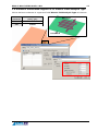
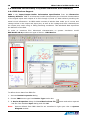
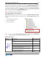
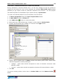
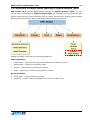
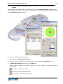
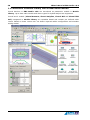
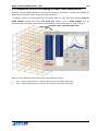
What is New in EMC Studio v.6.0 compared to version 5.1 Date: 25.11.2010 EMCoS 27 Pekin Str. 0160, Tbilisi GEORGIA Email: [email protected] Phone: +995-32-389091 Fax: +995-32-389092 http://www.emcos.com What is New in EMC Studio v.6.0 3 Contents 1 New Features v6.0 ............................................................................................... 5 1.1 New Features and Improvements in Matrix Partition Solution .................................5 1.1.1 Detection of Geometry Elements Related to Dielectric Substrate .....................6 1.2 New Features and Improvements in Multi Excitation Solution .................................7 1.3 New Ideology of S, Y, Z Solution – Multiport Solution ............................................8 1.3.1 Antenna Diversity Analysis by means of Correlation Coefficient.......................9 1.3.2 New 2D Post Processing Tool for Correlation Coefficient Observation ............. 10 1.4 Special Solution for Smart Entry Antenna System............................................... 11 1.4.1 Near Field Calculation in Volume – Near Field Grid ...................................... 11 1.4.2 Near Field Distribution in Near Field Grid ................................................... 13 1.4.3 Field Reference Level – Iso-line and Iso-surface Definition ........................... 14 1.5 LF Magnetic Field Analysis Type for Low Frequency Problems ............................... 15 1.6 Dielectric Substrates Support in LF Electric Field Analysis Type ............................. 17 1.7 Extension of Shield Shapes ............................................................................. 18 1.7.1 Shielded Ribbon Cables Support............................................................... 18 1.7.2 Outer Covering Support for Coaxial, Ribbon and Multi Cables ....................... 18 1.7.3 Wrap Shaped Shields Support.................................................................. 19 1.8 Extended Functionality in System Simulation and Schematic ................................ 20 1.8.1 IBIS Devices Support ............................................................................. 20 1.8.2 Bits Sequence Sources Support................................................................ 21 1.8.3 User - Defined Probes for Circuit File Devices ............................................. 23 1.8.4 Improved Wires Routing in System Diagram .............................................. 24 1.9 ASC File Extension ......................................................................................... 25 1.10 Improved Intersection Detection between Cables and Triangles .......................... 26 1.11 Extension of Object/Model Ideology to Hybrid Analysis Types ............................. 27 1.11.1 New Segments Grouping Functionality - Cable Routes ............................... 28 1.11.2 New Method for Hybrid Cables Creation - Based on Pre-defined Route ......... 29 1.12 Extension of Models Library with Virtual Bench Models....................................... 30 1.13 Improved 2D Post Processing for Near Field Observations .................................. 31 1.14 New 2D Post Processing Tool for Hybrid Analysis Type - Eye Pattern.................... 32 1.15 Full Support of Windows 7 ............................................................................. 32 2 Improvements v6.0 ........................................................................................... 33 What is New in EMC Studio v.6.0 5 1 New Features v6.0 1.1 New Features and Improvements in Matrix Partition Solution EMC Studio v6.0 provides improved Matrix Partitioning calculation scheme. This includes: Improvement of calculation scheme: less HD space required, easier parallel cluster calculations Optimized task processing: one input file definition for set of problems, one execution of computational solver Improvements in Layers organization for geometry objects Layer Sets for convenient definition of calculation task and separate view of each model variation Matrix Partition Calculation Tasks: Base Layer Layer 2 Layer 1 Layer 3 Layer 4 Task1 Task2 Task3 Task4 Task5 (Layers (Layers (Layers (Layers (Layers Set Set Set Set Set 1) 2) 3) 4) 5) = = = = = Base Base Base Base Base Layer Layer Layer Layer Layer + + + + + L1+ L2 L1 + L3 L1 + L2 + L3 L1 + L3 + L4 L1 + L2 + L3 + L4 6 What is New in EMC Studio v.6.0 1.1.1 Detection of Geometry Elements Related to Dielectric Substrate For correct simulations of glass antenna optimization problems using Matrix Partitioning scheme all metallic elements affected by dielectric substrate must be placed to the same Base Layer or Additional Layers Set as dielectric. New geometry selection tool provides fast and convenient access to triangles and wire segments related to particular dielectric substrate. In order to select wires or triangles near selected dielectric substrate(s): 1. Select dielectric substrate(s) to select corresponding geometry elements (wires or triangles) 2. Click Select button on Mesh Editor toolbar and in button popup menu select Triangles > Near Selected Dielectric Substrates or Wires > Near Selected Dielectric Substrates item All wires and triangles related to the selected dielectric substrate(s) will be selected: Selected triangles are located in the Extension Area of Dielectric Substrate What is New in EMC Studio v.6.0 7 1.2 New Features and Improvements in Multi Excitation Solution EMC Studio v6.0 provides improved Multi Excitation calculation scheme. This includes: Improvement of calculation scheme: less HD space required, easier parallel cluster calculations Optimized task processing: one input file definition for set of problems, one execution of computational solver Excitation Sets allows to group several excitation sources for convenient definition of calculation task V2_2 Multi Excitation Calculation Tasks: V1_2 Task1 (Excitations Set 1) = V1_1 + V2_1 Task2 (Excitations Set 2) = V1_2 + V2_2 Task3 (Excitations Set 3) = V1_3 + V2_3 V2_1 V1_1 V1_3 V2_3 8 What is New in EMC Studio v.6.0 1.3 New Ideology of S, Y, Z Solution – Multiport Solution EMC Studio v6.0 provides new ideology of Multiport solution. This includes: Easier calculation approach for analysis of multiport systems User-defined reference impedance User-defined type of output network parameters (S, Z or Y) New Port objects are introduced in TriD solver Antenna diversity analysis by means of Correlation Coefficient New 2D Post Processing Tool for Correlation Coefficient observation What is New in EMC Studio v.6.0 9 1.3.1 Antenna Diversity Analysis by means of Correlation Coefficient EMC Studio v6.0 provides new method for antenna diversity analysis by means of Correlation Coefficient: Port 1 Port 2 66 MHz 125 MHz Total Electric Field (Theta, Magn) [dBV] vs. Phi [deg] Frequency 66 MHz Frequency 125 MHz For convenient antenna Correlation Coefficient observation new 2D Post Processing Tool are available. 10 What is New in EMC Studio v.6.0 1.3.2 New 2D Post Processing Tool for Correlation Coefficient Observation EMC Studio v6.0 provides new 2D post processing tool for antenna correlation coefficient observation and analysis. To activate Correlation Coefficient dialog: Click Correlation Coefficient Select Results>Correlation Coefficient from Main Menu button on Post Processing bar What is New in EMC Studio v.6.0 11 1.4 Special Solution for Smart Entry Antenna System 1.4.1 Near Field Calculation in Volume – Near Field Grid EMC Studio v6.0 provides new observation quantity, Near Field Grid required for near field calculation and observation in volume. In this case field values are calculated in vertices of the defined near field grid. To define near field grid observation region: 1. Click Near Field Grid button on Elements Panel 2. In Create Near Field Grid dialog specify near field grid name (or use default) 3. Define Minimum, Maximum and Step values for each axis (N Points and Size values are recalculated automatically) 4. Define grid visualization settings in Grid Settings group. Three visualization modes are available (points, lines and surface) 12 What is New in EMC Studio v.6.0 Points View Lines View Surface View 5. Define points or lines visualization density by moving Density slider. For surface view move slider to set required transparency level 6. Click Create button Convert Near Field Grid to Field Probes: To convert near field grid to field probes: 1. Select near field grid in Viewer 3D or Tree View 2. Activate near field grid popup menu with right mouse click and select Convert to Field Probes item Near field grid will be converted to field probes located in the grid vertices: What is New in EMC Studio v.6.0 13 1.4.2 Near Field Distribution in Near Field Grid In order to allow observation of near fields in near field grid EMC Studio v6.0 provides updated Near Field 3D post processing tool. To view near field distribution in 3D grid: 1. Activate Near Field Distribution dialog 2. On General tab specify general observation parameters 3. Switch to Areas tab and choose Near Field Grid radio button 4. In 2D Plane group define normal vector (X, Y or Z) and plane level from Plane Level combo box or by moving corresponding slider If Use levels of whole grid is selected then field values for chosen plane level are recalculated related to min. and max. values of whole grid. Total Magnetic Field Distribution Plane level: z = 0.5 m Total Magnetic Field Distribution Plane level: z = 1 m If Enable automatic update check box is switched on then near field visualization in Viewer 3D will be dynamically updated. 14 What is New in EMC Studio v.6.0 1.4.3 Field Reference Level – Iso-line and Iso-surface Definition EMC Studio v6.0 provides new field reference levels visualization options for convenient analysis of smart entry antenna systems – Iso-line and Iso-surface modes. Total Magnetic Field Reference Level – Iso-line View Total Magnetic Field Reference Level – Iso-surface View Note: Iso-surface option is available only for fields calculated in near field grid. What is New in EMC Studio v.6.0 15 1.5 LF Magnetic Field Analysis Type for Low Frequency Problems New LF Magnetic Field Analysis Type in EMC Studio v6.0 provides environment for modeling of low frequency magnetic field interaction with thin 3D sheets characterized by combined resistive and magnetic properties. Automotive and industrial magnetic shielding problems can be effectively solved in frequency range from DC up to several MHz. Magnetic Field above the Aluminium Plate: 10 Measurement Numerical solution 9 8 Measurement Setup: Aluminium Shield B, T 7 6 5 4 3 2 1 0.01 0.1 1 10 Frequency, kHz 100 1000 16 What is New in EMC Studio v.6.0 Magnetic Field above the Steel Plate: Measurement Numerical solution 12 10 B, T 8 Measurement Setup: Steel Shield 6 4 1000 Peal part Imaginary part 2 Permeability 0 0.01 100 0.1 1 10 Frequency, kHz 100 Measurements are performed in AUDI AG, Germany 10 0.01 0.1 1 10 Frequency, kHz 100 1000 Magnetic Field Distribution Aluminum plate; f = 10 Hz Steel plate; f = 10 Hz Aluminum plate; f = 5 kHz Steel plate; f = 5 kHz 1000 What is New in EMC Studio v.6.0 17 1.6 Dielectric Substrates Support in LF Electric Field Analysis Type Infinite dielectric substrate is supported for LF Electric Field Analysis Type calculations: Dielectric Substrate Mutual Capacitance, (C11), [pF] No 2.8478 Yes 4.9843 Potential 1 Potential 0 18 What is New in EMC Studio v.6.0 1.7 Extension of Shield Shapes 1.7.1 Shielded Ribbon Cables Support EMC Studio v6.0 supports shielded ribbon cables in Hybrid Analysis Types: In order to define shield parameters for ribbon cables switch on Shield check box in Parameters Panel. 1.7.2 Outer Covering Support for Coaxial, Ribbon and Multi Cables EMC Studio v6.0 provides definition of outer covering for coaxial, ribbon and multi cables: What is New in EMC Studio v.6.0 19 Outer covering parameters (Material and Thickness) are defined in Outer Covering group in Parameters Panel of Cables Library dialog. 1.7.3 Wrap Shaped Shields Support EMC Studio v6.0 extends shield shapes and provides wrap shaped shields support for multi cables: Wrap Shield Circular Shield 20 What is New in EMC Studio v.6.0 1.8 Extended Functionality in System Simulation and Schematic 1.8.1 IBIS Devices Support IBIS is the Input/Output Buffer Information Specification from the Electronics Industry Alliance. IBIS is a behavioral model that describes the electrical characteristics of the digital inputs and outputs of a ECU through V/I and V/T data without providing the actual circuit information. An IBIS model consists of tabular data made up of current and voltage values in the output and input pins, as well as the voltage and time relationship at the output pins under rising or falling switching conditions. This tabulated data represents the behavior of the ECU. In order to introduce ECU behavioral characteristics to system simulation model EMC Studio v6.0 provides new type of device – IBIS Device. To define device data from IBIS file: 1. Activate Device Properties dialog 2. Choose IBIS device type from Device Type combo box 3. In Device Properties dialog click Load Device from file *.ibs file from standard Open dialog and click OK Note: button and select required Devices defined from IBIS data file are visualized in light cyan color in System Diagram window. What is New in EMC Studio v.6.0 21 After IBIS device creation all pins loaded from IBIS file are imported into Schematic environment as elements for circuit model construction. In Schematic Elements Tree all IBIS pins are located under the elements group having the same name as loaded IBIS file. Pin parameters loaded from IBIS file can be viewed and edited from Elements Properties dialog. For this purpose select pin in Schematic window, activate elements popup menu with right mouse click and select Elements Properties item. Note: HSpice model is used for IBIS devices. 1.8.2 Bits Sequence Sources Support EMC Studio v6.0 supports special type of sources in Schematic Elements Library, intended for bit signal generation in time domain tasks - Bits Sequence Sources. This includes: Pseudo Random Bits Sequence Random Bits Sequence Static Bits Sequence Note: In order to support Bits Sequence Sources in Spice calculations EMC Studio generates bit signal and converts the signal to PWL source. PRBS Voltage Source: Symbol Parameters Default Values Name V1 N (number of bits will be calculated by formula NBits = 2^N - 1) 4 VLow (voltage at low state) 0 VHigh (voltage at high state) 1 Rise Time (time required for a signal to change from VLow value to VHigh value), [s] 2 ns Fall Delay (time required for a signal to change from VHigh value to VLow value), [s] 2 ns Bits Length (pulse width), [s] 10 ns 22 What is New in EMC Studio v.6.0 Spice Syntax: V#name #node1 #node2 PRBS(#param1) PSpice Syntax: V#name #node1 #node2 PRBS(#param1) HSpice Syntax: V#name #node1 #node2 PRBS(#param1) Random Bits Sequence Voltage Source: Symbol Parameters Default Values Name V1 NBit (number of bits will be calculated by formula NBits = 2^N - 1) 16 VLow (voltage at low state) 0 VHigh (voltage at high state) 1 Rise Time (time required for a signal to change from VLow value to VHigh value), [s] 2 ns Fall Delay (time required for a signal to change from VHigh value to VLow value), [s] 2 ns Bits Length (pulse width), [s] 10 ns Spice Syntax: V#name #node1 #node2 RBS(#param1) PSpice Syntax: V#name #node1 #node2 RBS(#param1) HSpice Syntax: V#name #node1 #node2 RBS(#param1) Static Bits Sequence Voltage Source: Symbol Parameters Default Values Name V1 Bits Sequence (user defined sequence of bits) 101101110010 VLow (voltage at low state) 0 VHigh (voltage at high state) 1 Rise Time (time required for a signal to change from VLow value to VHigh value), [s] 2 ns Fall Delay (time required for a signal to change from VHigh value to VLow value), [s] 2 ns Bits Length (pulse width), [s] 10 ns Spice Syntax: V#name #node1 #node2 SBS(#param1) PSpice Syntax: V#name #node1 #node2 SBS(#param1) HSpice Syntax: V#name #node1 #node2 SBS(#param1) What is New in EMC Studio v.6.0 23 1.8.3 User - Defined Probes for Circuit File Devices During calculation of devices defined from *.cir file only voltages on pins are printed to output file and results for inner circuit elements are omitted. EMC Studio v6.0 provides possibility to get output results for particular elements of file devices. For this purpose user-defined probes can be added to spice syntax directly in Spice Editor. To create user-defined probes for circuit elements of the file device: 1. In Device Properties dialog click Open in Spice Editor button 2. In Spice Editor switch to Probes tab 3. Click Add Probe button to create new probe 4. New probe entry (with default type "Voltage") will be added to Probes Table 5. Choose required probe type "Voltage" or "Current" from Type column 6. Double click on probe entry in Name column and define probe name. Probe name definition depends on chosen probe type: "Voltage" - probe name should correspond to name of elements connection node defined in editor "Current" - probe name should correspond to elements full name defined in editor 7. Click OK To remove existing probes, select them in Probes Table and click Remove Probe button. 24 What is New in EMC Studio v.6.0 Defined probes will be appended to the loaded spice file as a comment with the following format: begin probes number_of_probes = N (number of defined probes) probe = m (probe index [from 1 to N]) type = Voltage or Current (type of probe) name = Probe name end probes 1.8.4 Improved Wires Routing in System Diagram Improved System Diagram in EMC Studio v6.0 provides smart rule for automatic routing of connector wires between devices: Old Wire Routing Rule in System Diagram New Wire Routing Rule in System Diagram What is New in EMC Studio v.6.0 25 1.9 ASC File Extension ASC file format is extended with additional information in EMCoS software products (EMC Studio, EMC Expert and Harness Studio Family). This includes: Cable Material Parameters (Insulation and Conductor Materials Parameters) Shield Parameters (Solid, Braided and Layered) Information about Cable Parts and Parameters (Single, TWP, Coaxial, Multi and Fiber) Devices and Splices Parameters Unit Definition for Exported and Imported ASC File Optimization of harness route definition and improved re-segmentation of imported harness ASC file format extension provides better data exchange capabilities between EMC Studio and other EMCoS products: Harness Studio Model EMC Studio Model 26 What is New in EMC Studio v.6.0 1.10 Improved Intersection Detection between Cables and Triangles Improved intersection detection between cables and triangles provides more convenient errors fixing procedure. Problematic cables and triangles are highlighted in Viewer 3D when corresponding errors are selected in Diagnostic Board. This provides fast and easy access to problematic regions. After manual correction of problematic areas corresponding error messages are disabled automatically without reapplying checking functions. This significantly optimizes model pre processing routines and saves time. Error messages are disabled automatically after proper changes in model What is New in EMC Studio v.6.0 27 1.11 Extension of Object/Model Ideology to Hybrid Analysis Types EMC Studio v6.0 extends Object/Model ideology to Hybrid Analysis Types. In new version object parameters of Hybrid Analysis Type are extended with user-defined Cable Routes (special group of the segments used for cables construction). Hybrid cables created based on Cable Routes are also considered as Object/Model parameters. Cables and cable routes have the following attributes: Cable attributes: Cable Name - unique name of the hybrid cable defined based on route Part Number - reference to a library cable Position – 2D position in bundle cross section Route - reference to route on which cable is created Route attributes: Route Name - unique name of the route Segments - unique name of the segments included in cable route 28 What is New in EMC Studio v.6.0 1.11.1 New Segments Grouping Functionality - Cable Routes Segments intended for hybrid cables creation can be combined into special groups called Cable Routes. These groups can be used as pre defined routes during cables creation procedure. Route 2 Route 1 Note: Cable routes and cables defined based on them are stored as a part of EMC Studio object which can be exported to the external *.emm (EMC Model) files or added to Models Library. In order to create new cable route based on selected segments activate segments popup menu and choose Create Cable Route on Segment(s) item. Note: One segment can belong to several routes. Cable routes can be added, edited or deleted directly from Object Properties dialog. To view and modify cable routes properties: 1. Select object in Elements Tree View 2. Activate objects popup menu with right mouse click and select Properties… item 3. In Object Properties Cable Routes tab dialog switch to Cable Routes section displays all cable routes created in current object and provides editing functionality: Add Route - creates new cable route Edit Route - edits cable route content (allows to add or remove segments) Delete Route - deletes selected cable routes What is New in EMC Studio v.6.0 29 1.11.2 New Method for Hybrid Cables Creation - Based on Pre-defined Route When cables are created based on pre-defined routes in Hybrid Analysis Types they are automatically added to the active objects parameters and can be accessed or edited directly from Objects Parameters dialog. To view and modify cables properties: 1. Select object in Elements Tree View 2. Activate objects popup menu with right mouse click and select Properties… item 3. In Object Properties dialog switch to Cables tab Cables section displays all cables created in current object and provides editing functionality: Add Cable - creates new cable Edit Cable - edits cable parameters Delete Cable - deletes selected cables 30 What is New in EMC Studio v.6.0 1.12 Extension of Models Library with Virtual Bench Models Virtual benches in EMC Studio v6.0 are introduced as parametric models in Models Library. Up to date cable models and device types for hybrid analysis are supported. Virtual bench models (Virtual Antenna, Virtual Stripline, Virtual BCI and Virtual TEM Cell) integrated in Models Library are variables based and contain pre defined cable routes. Based on these routes user can define required cables configuration and simulate testing model. What is New in EMC Studio v.6.0 31 1.13 Improved 2D Post Processing for Near Field Observations Preview of field probes selected in 2D post processing is available in centers of triangles for Near Field Areas and in grid vertices of Near Field Grid. To display preview of field probes for near field areas or near field grid activate Field in Field Probes dialog and select All from file option. List of Field Probes will be automatically filled with field probes corresponding to near field areas or near field grid. Preview of the selected field probes Names of the obtained field probes have the following format: "nfa" + Near Field Area ID + internal ID of point from Near Field Area "nfg" + Near Field Grid ID + internal ID of point from Near Field Grid 32 What is New in EMC Studio v.6.0 1.14 New 2D Post Processing Tool for Hybrid Analysis Type - Eye Pattern EMC Studio v6.0 provides new 2D post processing tool Eye Pattern. Eye Pattern post processing tool allows to analyze signal integrity results obtained for System Simulation, Hybrid Cross Talk and Susceptibility analysis in Time Domain calculations. To activate Eye Pattern dialog: button on Post Processing bar Click Eye Pattern Select Results>Eye Pattern from Main Menu 1.15 Full Support of Windows 7 EMC Studio v6.0 provides full support of Windows 7 operating system. What is New in EMC Studio v.6.0 33 2 Improvements v6.0 Improvements in Computational Cores Faster LC calculation with LF Electric Field solver Improved construction of cable bundle cross-section Binary format for TriD output file is supported Improved output file for time domain TriD calculations Definition of multiple calculations for stochastic cables analysis is available in XTalk and Radiation Hybrid solvers Slight improvements in S2Cir converter User's Manual for Hybrid Cores is available Support of Multiple Near Field Sources and Impressed Currents Improvement of Cables Auto-bundling for Random Type Improved Processing of Imported Touchstone and *.cir Devices in Schematic and Cores Improvements in System Diagram and Schematic Improved automatic placement of devices View of indexes of circuit element pins in Schematic Improvements in Cables Library Units for all cable types are changed from meters to millimeters Improved definition of shield parameters Additional parameter Angle for internal wires of multi cables Cables description generation for all cable types Convenient Selection of Splices Improved Union Segments Functionality Possibility to Edit Input File for Hybrid Analysis Type for Advanced Users Improvements in Post Processing Mode Improved field probes processing Convenient Handling of Near Field Areas in 3D Post Processing Improvement of Static2D Viewer GUI Improvements