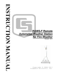
1
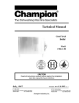
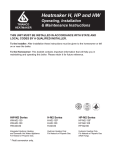
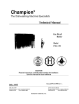
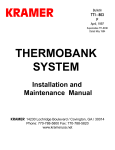
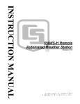
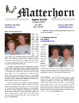
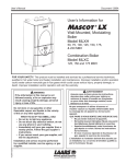
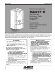
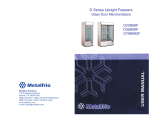
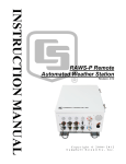
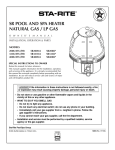
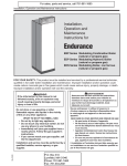
Service Manual
Document 2109
Service Manual for
9600 CB & HWG
HWG-M2 Series
HWG-M2-250
HWG-M2-200
HWG-M2-175
HWG-M2-150
Hot Water Generator
For Natural or
Propane Gas
CB-M2 Series
CB-M2-250
CB-M2-200
CB-M2-175
CB-M2-150
Condensing Boiler
For Natural or
Propane Gas
FOR YOUR SAFETY: This product must be installed and serviced by a professional service technician,
qualified in hot water boiler installation and maintenance. Improper installation and/or operation could
create carbon monoxide gas in flue gases which could cause serious injury, property damage, or death.
Improper installation and/or operation will void the warranty.
WARNING
If the information in this manual is not followed exactly, a fire or explosion may result
causing property damage, personal injury or loss of life.
Do not store or use gasoline or other flammable vapors and liquids in the vicinity of this or
any other appliance.
WHAT TO DO IF YOU SMELL GAS
• Do not try to light any appliance.
• Do not touch any electrical switch; do not use any phone in your building.
• Immediately call your gas supplier from a nearby phone. Follow the gas supplier's
instructions.
• If you cannot reach your gas supplier, call the fire department.
Installation and service must be performed by a qualified installer, service agency, or gas
supplier.
LAARS Heating Systems
Page 2
TABLE OF CONTENTS
SECTION 1.
General Information
1A.
1B.
1C.
1D.
1E.
1F.
1G.
1H.
1I.
1J.
1K.
1L.
1M.
1N.
Introduction ................................................... 3
Start Up Procedures ..................................... 9
Checkout Procedures ................................... 9
Cleaning the Combustion Chamber Coil .... 10
Diverting Valve ........................................... 10
Safety Limit Switch ..................................... 10
Boiler Control .............................................. 10
Stack Switch ............................................... 11
Igniter .......................................................... 11
Transformer ................................................. 11
Unit Pump ................................................... 11
Blower ......................................................... 11
Gas Valve ................................................... 11
Time Delay Relay (TDR) .............................. 11
1O.
1P.
1Q.
1R.
1S.
1T.
1U.
1V.
1W.
1X.
1Y.
Operating Control ........................................ 11
Vent TCO .................................................... 12
Intake TCO .................................................. 12
Thermal Cut-Out (TCO) ................................ 12
Delayed Ignition ........................................... 12
High Gas Consumption ............................... 12
Noisy Operation .......................................... 12
Short Cycling .............................................. 13
Lock Outs (& Trip Outs) .............................. 13
Routine De-Liming Procedure ...................... 14
Sequence of Operation ................................ 14
SECTION 2.
Troubleshooting
2A.
Code ........................................................... 15
9600 CB & HWG Service Manual
SECTION 1.
General Information
1A. Introduction
The Heatmaker 9600 CB condensing boilers and
the Heatmaker 9600 HWG non-automatic circulating
tank water heaters have a dual heat exchanger (H-X)
design. The primary H-X is a copper coil type which
operates in a non-condensing mode. A secondary
stainless steel H-X (economizer) surrounds the primary
H-X to condense water vapor from the flue gases and
extract the maximum amount of heat from the
combustion process. Condensate from the economizer
drains into the bottom of the outer shroud of the boiler
section and into the exhaust duct which provides for
condensate drainage.
Flow rates through the primary H-X are
controlled by a thermostatic diverting valve which
diverts water, as required, from the outlet of the
Figure 1. Heatmaker 9600 Assembly View.
Page 3
primary H-X back to its inlet so that the primary H-X
temperature is always maintained above the
condensation temperature of the water vapor in the flue
gases. A circulator is built into the unit to provide
enough head to circulate water through the H-X’s and
to a secondary heating loop or separate hot water
storage tank.
The forced draft premixed combustion system
contains a blower to provide air flow through the unit,
the air inlet and exhaust piping. The cylindrical burner
is provided with an air/gas mixture which is metered
through fixed orifices. A hot surface igniter (glow coil)
is controlled by the Integrated Boiler Control which
also controls the blower, circulator, and gas valve and
provides for burner flame safety.
The Heatmaker 9600 is designed to use 3" PVC*
or ABS DWV pipe or PVC, ABS or CPVC schedule
40 pipe for both air intake and flue material. Vent
terminations are provided with the unit.
* CB / HWG - M2- 250 flue material can only be ABS or CPVC.
(1)
Diverting valve
(2)
Circulator
(3)
Mixer tube
(4)
Exhaust
(5)
Blower
(6)
Gas valve
(7)
Burner
(8)
Economizer
(9)
Combustion coil
(10)
Cold water inlet
(11)
Hot water outlet
(12)
Heat exchanger drain
(13)
Air vent
LAARS Heating Systems
Page 4
A PORTION OF
HOT WATER
IS RECYCLED
TO MAINTAIN
COMBUSTION
COIL INLET
TEMPERATURE
AT 140°F
THERMOSTATIC
DIVERTING
VALVE
(160° F THERMOSTAT)
(E)
(D)
(B)
(A)
COMBUSTION
COIL
ECONOMIZER
(A) Cold Water Inlet From Tank or System
(B) Economizer Outlet (10°F Rise above inlet)
(C) Combustion Coil Inlet 130-140°F Typical
(D) Combustion Coil Outlet
(E) Hot Water Outlet To Tank or System 160 - 170°F Typical
Figure 2a. Water Flow through a Heatmaker 9600.
HWG - Before S/N 394 - 068
CB - Before S/N 795 - 0014
9600 CB & HWG Service Manual
Page 5
1
2
3
4
5
6
7
8
9
10
11
12
A
B
C
D
Figure 2b. Water Flow through a Heatmaker 9600.
HWG - After S/N 394 - 067
CB - After S/N 795 - 0013
Legend
Mixing Valve
Internal Pump
Mixer Tube
Flue Outlet
Combustion Fan
Air Pressure Switch
Burner
Secondary Heat Exchanger
Primary Heat Exchanger
Return (From Primary Loop)
Gas Valve
Flow (To Primary Loop)
Secondary Heat Exchanger Inlet
Secondary Heat Exchanger Outlet
Primary Heat Exchanger Inlet
Primary Heat Exchanger Outlet
LAARS Heating Systems
Page 6
EXHAUST
INTAKE
TERMINAL
43
WALL
PLATE
50
EXHAUST
TERMINAL
AIR
INTAKE
44
WALL
PLATE
45
AIR
ORIFICE
GAS
ORIFICE
1
2
COMBUSTION
COIL
GAS
ECONOMIZER
7
FLAMEHOLDER
46
REFERENCE PAGE 8 FOR PART NUMBERS
Figure 3. Air/Fuel Flow Through Heatmaker 9600.
EXHAUST
ASSEMBLY
CONDENSATE
9600 CB & HWG Service Manual
Figure 4. Cut Away View of Heatmaker 9600.
Figure 5. Control Box.
Page 7
LAARS Heating Systems
Page 8
32
HIGH LIMIT
SAFETY
SWITCH BOX
31
38
OPERATING LIMIT
CIRCULATOR PUMP
CONTROL BOX
SUB-ASSY
HEATMAKER
9600
BLOWER
ASSEMBLY
16
BLOCKED
FLUE
DETECTOR
30
IGNITER ASSY
6
GAS VALVE
36
VENT
THERMAL
CUT OUT
INTAKE
THERMAL
CUT OUT
THERMAL
CUT OUT
34
33
35
Figure 6. Control Components
#
1
Part Description
Part #
Combustion Coil (Primary H-X) HWG
2400-086
Combustion Coil (Primary H-X) CB
2400-284
2
Economizer Coil (Secondary H-X)
10-078
3
Upper Head
10-034
4
Inner Shroud
10-112
5
Outer Shroud
10-124
Ignitor (w/Gasket) after s/n 391-126
6
2400-286
791-044
6
Ignitor, before s/n 391-127 791-045
2400-248
7
Burner (Flameholder) (w/Gaskets)
2400-082
Burner (w/Gaskets) (250 Series)
2400-308
8
Upper Insulation (Blanket)
10-048
9
Upper Insulation (Board)
10-050
10
Lower Insulation (Board)
10-106
11
Lower Insualtion (Blanket)
10-108
12
Gasket, Igniter (1 req'd)
10-332
13
Gasket, Burner (2 req'd)
10-338
14
Gasket, Blower Inlet (1 req'd)
1-254
15
Gasket, Blower Discharge (1 req'd)
10-324
Gasket, Blower Discharge (250 series)
11-066
16
Blower Assembly (w/Gaskets)
2400-079
Blower Assembly (w/Gaskets) (250)
2400-310
17
Orifice, Air
*
18
Orifice, Gas
*
19
Orifice Union
1-252
20
Mixer Tube
10-252
Mixer Tube (250 Series)
11-016
21
Air Duct Hose
1-458
Air Duct Hose (250 Series)
11-038
22
Gas Valve Balance Line
2400-026
*Not available separately - purchase orifice kit for type of gas
and input desired.
#
23
24
25
26
27
28
29
30
31
32
33
34
35
36
37
38
39
40
41
42
43
44
45
46
Part Description
Jacket, Front Removeable
Jacket, Top
Jacket, Bottom
Control, Boiler Integrated
Transformer, 40 VA
Time Delay Relay
Wiring Harness
Stack Switch
Operating Control
Safety Limit
Intake T.C.O.
Exhaust T.C.O.
T.C.O.
Gas Valve
Gas Valve (250 Series)
Capacitor (Blower Start/Run)
Pump, Grundfos UP 26-99-BF CB
CB-250
HWG
HWG-250
Valve, Pressure Relief (150 PSI)
Valve, Pressure Relief (250 Series)
Valve, Pressure Relief (125 PSI)
Valve, Pressure Relief (250 Series)
Diverting Valve (Complete)
Thermostat (O-Rings
included)(160°F)
before S/N 394-068 or 795-0014
Thermostat (O-Rings
included)(140°F)
before S/N 394-067 or 795-0013
Terminal, Intake
Terminal, Exhaust
Flange, Wall, Vent Pipe
Exhaust Assembly
Exhaust Assembly (250 Series)
* Specify Serial Number
Part #
10-402
10-406*
10-010
2400-224
2400-006
2400-062
10-354
2400-110
2400-056
2400-055
2400-058
2400-058
2400-020
2400-014
2400-015
2400-088
2400-386
2400-387
2400-388
2400-389
2400-094
2400-095
2400-096
2400-097
2400-001
2400-129
2400-130
2400-102
2400-104
2400-100
2400-390
2400-402
9600 CB & HWG Service Manual
Page 9
1B. Start Up Procedures
Make sure that the system is properly filled, completely purged of air and system valves are open.
2. Open system gas cock(s) and gas control knob on
gas valve (if closed).
3. Set the room thermostat, aquastat or storage tank
aquastat to call for heat.
4. Turn on electrical power to the unit.
5. The green light on the boiler control will light and
the internal circulator and blower will start. After
a 15 second prepurge the igniter will come on for
20 seconds and then the gas valve will open and
ignition will occur (for more details see
“Sequence of Operation”).
Note: Air in new gas lines may prevent ignition.
The boiler control will make a total of three attempts
for ignition before lockout. To reset the control, switch
off the power switch for 10 seconds.
EXHAUST
TERMINAL
1.
1C. Checkout Procedures
1.
2.
Check burner input rate:
Allow burner to operate for at least 5 minutes
before checking the input. On most LP
installations it will be impossible to check the
input, however, checking combustion as in step 2
below will guarantee proper burner operation. To
check the input (where possible) time the gas
meter to determine the time required for 4 cubic
feet of gas to pass through it. No other equipment
supplied by the gas meter should be operating
when the timing is done. Table 1 can be used to
convert the time to input rate.
Due to the effects of altitude and other minor
variances, it is possible that the input rate will
differ slightly from the rating plate value.
Check combustion (see Figure 7).
It is important to check the combustion with a
CO2 or O2 tester (Bacharach for example) to
ensure maximum efficiency and reliability. Insert
Time (4CF)
57 sec
58
Input Rate (Natural Gas)
252,600 BTU/hr
248,300
59
244,000
70
71
205,700
202,800
72
74
200,000
194,600
80
82
180,000
175,600
84
171,400
94
96
153,200
150,000
98
146,900
Table 1. Time-to-Input Rate Conversion.
1/4 IN. PER FT.
COMBUSTION
TESTER
SAMPLE
TUBE
9600 CB
Figure 7. Checking Combustion.
the tester sample tube through the exhaust
terminal and at least 6" (152mm) into the flue
pipe. The unit must operate for 5 minutes before
taking a sample. Take a sample and determine the
CO2 or O2
CO2 - 8% to 8.5% (natural gas)
O2 - 7% to 6%
CO2 - 9% to 9.8% (propane gas)
If the burner is not operating in this range it
should be adjusted (see Burner Adjustment).
3. Burner Adjustment
The Heatmaker 9600 CB & HWG burner system
is a pre-mixed forced combustion system. Outside
air is drawn through the air orifice (located in the
rubber hose in the air induction system) and
mixed with the gas which is drawn in downstream
of the air orifice. All the air required for complete
combustion comes into the system in this manner.
The gas is metered through the gas orifice located
in the gas orifice union.
Adjusting the burner is limited to changing the
gas orifice to achieve proper combustion. The air
orifice cannot be altered and the gas valve
pressure should not be changed.
Before changing the gas orifice to adjust the
burner, make the following checks:
a. Gas valve supply pressure is between 4 and
14 in. W.C. (2.3 and 8.1 oz / in²)
b. The differential pressure on the outlet side
of the gas valve (manifold pressure) is
between -0.05 and -0.35 in. W.C.
If a. and b. are correct proceed as follows:
When measuring CO2 (natural gas units),
readings below 8% generally indicate lean mixture (not
enough gas). Reading above 9 1/4% indicate a rich
mixture (too much gas). Readings for LP units are
higher; below 9 1/4% is lean and above 10 3/4% is
rich. If the readings are below the minimum values,
install a larger gas orifice. If the readings are above the
maximum value install a smaller orifice.
LAARS Heating Systems
Page 10
COMBUSTION
COIL
MANIFOLDS
ECONOMIZER
OUTLET
ECONOMIZER
INNER
SHROUD
MANIFOLD
DRAIN
ECONOMIZER
RETAINERS (4)
OUTER SHROUD
CLAMPS (4)
COLD WATER
INLET
PLASTIC FLANGE,
(4) NUTS
Figure 8. Disassembly.
1D. Cleaning the Combustion
Chamber Coil
Note: In normal operation this procedure is
seldom required. Should it prove necessary, the
following procedure is used to access the coil for
cleaning.
1. Turn off gas and electrical power to unit.
2. Remove upper and lower front covers.
3. Disconnect flue and combustion air pipes and
remove jacket top.
4. Remove flue pipe assembly by disconnecting
from outer shroud.
5. Remove mixer tube and blower assembly.
6. Remove igniter and burner (flameholder).
7. Fit mask and eye protection.
8. Fit mask and eye protection.
9. Locate vacuum hose at flue outlet of outer
shroud and start vacuum cleaner.
10. Bend air chuck extension 90° at a point about
2-3" from end.
Insert air chuck extension through burner hole in
upper head. Direct end of extension toward fins of
heat exchanger and blow off accumulated residue.
Methodically move up and down and completely
around the heat exchanger. After completion of this,
remove the extension from the burner hole and inspect
the condition of the heat exchanger with a flashlight
and inspection mirror. If there are areas on the heat
exchanger that still have some residue, repeat the
process on those areas until the heat exchanger is
clean.
After the heat exchanger is clean, remove the
vacuum cleaner from the outer shroud flue outlet and
stop vacuum cleaner.
Carefully inspect the seal between the outer
shroud and the upper head and the joint in the outer
shroud. If there is any evidence of leakage from either
of these joints, clean off the silicone in that area and
prepare the surface for resealing. Commercially
available oven cleane is an appropriate cleaning agent.
Reseal the affected areas witih silicone, reassemble all
parts in the reverse order and check boiler operation.
1E. Diverting Valve
The diverting valve is a thermostatically
controlled device which keeps the primary heat
exchanger (H-X) from operating in the condensing
mode. When return water from the storage tank or the
system is below 130°F (54°C) the diverting valve
recycles a portion of the outlet water from the primary
H-X back to the primary H-X inlet so that the
minimum temperature required to prevent
condensation on the primary H-X is maintained at
160°F (71°C). The thermostat element is similar to
those used in large industrial engines.
To change the thermostatic element, valve off
the unit and turn off electrical power. Open boiler
drain to relieve pressure and close again. Remove the
cap screws (3) and remove top of valve. Remove and
replace the element (with barrel up), spring and sealing
disc. Place O-ring under valve top and replace top.
Secure with cap screws and tighten. Turn on valves
and bleed air from the top of the diverting valve. Turn
on electrical power and restart unit.
1F. Safety Limit Switch
The Safety Limit Switch has a fixed set point of
245ºF (118°C). It has a manual reset button which
may be reset at temperatures below 240ºF (116°C).
To replace the switch, shut off the 120 volt
power and valve off the unit. Drain a gallon of water
from the boiler and remove the 3/8 NPTM fitting
which seals the capillary. Remove the two screws
which hold the switch to the side panel, remove the
switch and unplug the switch wires. Install the
replacement in the reverse order, open isolation valves
and bleed air from the diverting valve petcock. Switch
on 120 volt power and restart unit.
1G. Boiler Control
The boiler control controls the combustion
process, the gas valve, the igniter, the blower, and the
unit pump.
It provides blower prepurge as well as burner
flame sensing. When replacing the boiler control all
plugs are color coded and it is not possible to miswire
the control. See sequence of operation for operating
details.
9600 CB & HWG Service Manual
1H. Stack Switch
The Stack Switch is a normally open single pole
switch which is operated by the pressure difference
across the air orifice. It is set to close when a static
pressure difference of 1 in. W.C. is generated by the
combustion air blower. Its function is to prove airflow
and to inhibit burner operation in the event of flue
stoppage. The switch is wired directly to the boiler
control. It is located on the inside of the jacket back
panel.
1I. Igniter
The Igniter is a “glow bar” type silicone carbide
unit. It is energized whenever there is a call for heat
and the red “IGNITER” light on the boiler control is
lit. After the igniter is switched off and boiler continues
to run, the igniter functions as a flame sensor for the
boiler control.
If the igniter fails and must be replaced, always
install a new igniter gasket with the replacement
igniter.
1J. Transformer
The control transformer accepts 120 VAC power
and provides 40 VA of 24 VAC power for the boiler
control only. It is not capable of supplying control
power for external devices such as zone valves. They
must have their own separate power supply.
1K. Unit Pump
The unit pump is a wetted rotor type pump which
operates whenever there is a call for heat or hot
water.
If a pump change is required for any reason,
valve off the boiler and drain approximately 1 or 2
gallons of water (3.79 to 7.58L) from the unit through
the drain under the chamber. Drain is accessed by
removing lower front panel. Turn off the main
disconnect switch and unplug the pump wires, remove
the pump motor. The pump housing need not be
removed. The replacement pump motor should be
installed in the reverse order from which the old pump
motor was removed. After filling the system, be sure to
bleed air from the diverting valve petcock.
1L. Blower
The combustion air blower is a high head
centrifugal blower,. It is designed to provide about 4"
W.C. of suction at 43 CFM. This performance is
necessary to operate the gas valve reliably, to
overcome induction system friction losses and to
eliminate any sensitivity to wind striking the vent
terminal. It is powered by a 120 volt motor which
draws about 1.65 amps at rated load. It is controlled
by the boiler control. Whenever there is a call for heat
and 30 seconds after, the blower should be energized.
If a blower change is required, turn off the 120 volt
Page 11
power and unplug the power wires from the blower
motor. Disconnect intake exhaust vents and remove top
jacket. Remove the six bolts and nuts from the blower
discharge flange and the four nuts from the blower
inlet flange. The blower may now be deflected enough
to permit its removal. Replace the new blower using
new gaskets, in the reverse order from which the old
blower was removed. The four Inlet flange nuts,
however, should only be finger tight initially and then
tightened with a wrench after all other operations have
been completed. The combustion should be checked for
correct air-fueled ration whenever the blower is
replaced (see Burner Adjustment.)
1M. Gas Valve
The gas valve is a solenoid operated, negative
pressure regulated valve. The outlet pressure is
regulated at minus .2 inches W.C. It is designed to
operate with supply pressures of 4-14 inches W.C.
Within that range of supply pressures, the regulated
discharge pressure may vary from minus .05 to minus
.35 inches W.C. The regulator is not adjustable and the
effect of this variation in discharge pressure is not
significant. Because of the fixed regulator setting, gas
flow must only be adjusted by changing the gas orifice.
To remove the gas valve, shut off the 120 volt
power and the master gas cock in gas line, loosen the
nut on the gas orifice union and remove the orifice
union plus piping to the gas valve. Disconnect the
wires from the gas valve. the valve may now be
unscrewed from the inlet piping. It may be necessary
to deflect the inlet piping somewhat in order to clear
the boiler jacket. After the valve has been removed,
replace with a new valve in the reverse order in which
the old valve was removed. Do not overtighten the
fittings into the valve body as this may cause damage
to the valve.
1N. Time Delay Relay(TDR)
The time Delay Relay controls the unit pump and
keeps it operating for approximately one minute after
the blower post purge stops. This function dries out the
moisture in the chamber to prevent corrosion. Control
voltage on the TDR is 24 volts from the limit circuit.
The contacts to supply pump power are 120 VAC.
They open one minute after the 24 volt control voltage
is interrupted. Turn off disconnect switch before
changing TDR.
1O. Operating Control
The operating control functions as a high limit to
prevent boiler outlet temperatures from exceeding
210°F (99°C) on CBs and 185°F (85°C) on HWGs
during periods of low load or high return water
temperatures. It will reset automatically when the
boiler temperature drops to 170°F (77°C). To replace
immersion type, valve off boiler and drain about a
Page 12
gallon of water from it. Turn off electrical power and
disconnect wires from operating control. Remove
operating control from diverting valve body and
replace with new control. Connect wires to control and
open isolation valves. Bleed air from the diverting
valve petcock, turn on electrical power and restart
boiler. The strap on type may be changed without
draining.
1P. Vent TCO
The vent TCO is a normally closed temperature
switch which functions to shutdown the burner if flue
gas temperatures exceed 180 - 200ºF (82-93°C). It is
mounted on the 3" (76mm) exhaust pipe inside the unit
between the top of the lower panel and the top. Switch
off electrical power when changing this safety.
1Q. Intake TCO
The intake TCO is a temperature switch with
normally closed contacts which open on a temperature
rise at 180°F (82°C). It is identical to the vent TCO
and functions to interrupt power to the gas valve if the
mixer tube temperature exceeds 180°F (82°C). It is
mounted on the mixer tube about 3" (76mm) above
burner flange. Switch off electrical power when
changing this safety also.
1R. Thermal Cut-Out (TCO)
The thermal cut-out is a probe type temperature
switch with normally closed contacts which open on a
temperature rise at 450°F (232°C). It is located on the
right side of the upper head with the probe extending
down into the exhaust passage between the boiler coil
and the economizer coil. It functions to interrupt power
to the gas valve if the flue gas temperatures exceed
450°F (232°C) for any reason. Switch off electrical
power when replacing.
1S. Delayed Ignition
1.
2.
3.
4.
Possible Causes - Time of occurrence
High lockups on LP - occurs on start up.
Gas valve regulation problem - occurs on start up.
Defective burner (flameholder) - occurs primarily
on burner shutdown
Natural gas orifice in LP unit - occurs on startup
High lock up pressures on LP fuel systems are
the most common cause of delayed ignitions on
Heatmaker boilers. The high LP supply pressure
results from improper second stage regulator selection
or a faulty regulator.
It can be detected by measuring the gas supply
pressure to the unit at the inlet pressure tap on the gas
valve. Use a water manometer or pressure gage with a
scale reading of at least 25 in. W.C. or 1 oz/in 2.
Install the pressure tap in the 1/8 NPTF plugged port
LAARS Heating Systems
located above the gas inlet port on the gas valve. The
gas supply to the boiler must be shut off before making
this connection. The Heatmaker boiler is designed to
operate with supply pressures of 4-14 in. W.C. (8.1 oz/
in2) with the boiler not operating it is likely that this is
the cause of the delayed ignition. Lock up pressures
must be measured when the boiler is not operating and
preferably immediately after boiler shutdown.
Gas valve regulation problems can also cause
delayed ignitions. To detect gas valve regulation
problems it is necessary to have an inclined manometer
or a Magnehelic pressure gage. The normal gas valve
regulator setting is -0.2 IN. W.C. This should happen
smoothly without allowing pressure spikes positive
when the solenoid opens then the gas valve regulator is
faulty and may be the cause of the delayed ignition.
A defective burner (flameholder) can cause a
delayed ignition however not often. If the gas supply
pressure and the gas valve are functioning properly and
the air and gas orifices are correct the burner should be
inspected. To inspect, remove the mixer tube and the
burner will lift out of the top of the chamber. There
should be no perforations other than the punched holes.
Replace in the reverse order with new gaskets.
1T. High Gas Consumption
Improper burner operation caused by incorrect
air/fuel ratio (CO2 or high O2 out of the specified
range) will cause high gas consumption. It is most
noticeable on LP fired units with low CO2 or high O2,
however, units operating on LP or natural gas with
incorrect air/fuel ratios will not provide their best
efficiency. If no combustion analyzing equipment
(CO2 or O2) is available, an indication of the air/fuel
ration can be gotten by briefly sniffing the flue gases.
When running properly the Heatmaker’s flue gases
should have no smell. If they have a strong piercing
smell, the gas orifice is probably too small. Do not
attempt to do re-orificing without an O2 or CO2 kit.
1U. Noisy Operation
There are two principal sources of excessive
noise.
1. Combustion
2. Boiling (kettling or knocking)
Combustion noise can occur when the burner is
operating with a very rich or a very lean mixture. A
rich mixture (high CO2 or low O2 - gas orifice too
large) will cause a high pitched noise that is loudest at
the vent terminal. A lean mixture (low CO2 or high O2
- gas orifice too small) will cause a very uneven
rumbly noise and may sometimes be associated with a
nuisance lockout situation and a strong piercing odor
at the vent terminal. Both noises may be eliminated by
proper burner adjustment (see Burner Adjustment).
9600 CB & HWG Service Manual
Boiling noises can occur because of air in the
secondary loop of a heating system (9600 CB
applications) or because of pump failures in either the
9600 CB or 9600 HWG.
Another boiling noise which occurs primarily on
9600 HWG units can result from liming of the primary
heat exchanger. This noise is more pronounced and
may occur at any temperature. If the pump appears to
be operating properly and the unit continues to run
normally except for the knocking sound then liming
should be suspected and the unit should be de-limed
according to the “Routine De-liming Procedure”. If the
knocking is very sever, de-liming may not stop the
noise and the primary heat exchanger will need to be
replaced.
The knocking sound may also exist on 9600 CB
and 9600 HWG units for a very short time followed by
a safety limit trip out. The generally results from total
pump failure (impeller sheared off or motor not
running at all).
1V. Short Cycling
1.
2.
There are two different types of short cycling
System related
Combustion related
The most common cause of system related short
cycling is boiler oversizing (9600 CB). Because the
9600 CB is a low mass boiler with high output it will
short cycle if system load or water flow are insufficient
to accept all of its output. This situation may also
occur with a properly sized boiler when it is installed in
a zoned system and one or more of the zones are very
small. If a small zone causes the problem then it may
be necessary to only allow that zone to
operate when another zone is calling.
This can be accomplished without
repiping in a zone valve system by disconnection the
end switch wire from
the zone valve which controls the small zone(s). If the
boiler is oversized, cycle
time may be reduced by reducing the
boiler input. An orifice kit is available to reduce input
from 200,00 BTU/HR to 150,000 BTU/HR or
175,000 BTU/HR.
System related short cycling can also occur on
9600 HWG Units. It results from very high aquastat
settings on the storage tank. Settings higher than 160°170°F (71°-77°C) should be suspected of being the
cause. Many times tank aquastats are set high to
compensate for an undersized system. If they are set
too high and the unit short cycles then the output from
the system will actually be reduced.
Combustion related short cycling occurs when the
burner is incorrectly adjusted. Lean mixtures (low
CO2 or high O2) cause the boiler control to lose the
flame signal. The control then causes a restart and if
Page 13
the flame signal is sensed on the restart then the
burner will operate again. The intermittent sending and
losing of the flame signal by the boiler control causes it
to short cycle the burner. If combustion related short
cycling is suspected refer to “Checking Combustion”.
1W. Lock Outs (& Trip Outs)
1.
2.
3.
4.
The principal cause of nuisance lockouts are
moisture in the combustion chamber
poor combustion
igniter failure
short cycling
Safety limit trip outs are generally caused by low
flow or recirculation in the primary heat exchanger.
Moisture in the combustion chamber can be
caused by a failure of the thermostatic element in the
diverting valve. If the element fails in the full open
position, it will cause the primary heat exchanger to
operate in the condensing mode by allowing low outlet
temperatures. This condition should be suspected if
boiler outlet temperatures are consistently below 160°F
(71°C). The moisture causes a loss in flame sensing
and the boiler control will shut the unit down.
Poor combustion may cause a boiler control
lockout by transmitting a very weak flame signal to the
boiler control. The boiler control senses a flame using
the flame recertification principle. This principle
utilizes the fact that a flame is not only conductive but
it converts AC voltages to DC. The igniter which
becomes a flame sensor after it is deenergized as an
igniter has an AC voltage applied to it by the control.
If a flame exists the AC is converted to DC and
conducted to ground through the burner or the primary
heat exchanger.
Since natural gas or LP are neither conductive
nor capable or rectifying an AC voltage to DC, the
burner control can determine if a flame exists or not by
the presence of DC or AC current. Poor combustion
can make this decision difficult because of poor
conductivity. There are many causes for poor
combustion. Incorrect burner adjustment is the most
obvious, however, a blocked condensate drain or an
improper flue installation can cause a restriction in the
flue which will cause poor combustion. If there is a
restriction in the flue from condensate or rain water
buildup a gurgling sound can be heard at the vent
terminal.
Igniter failure may also cause a nuisance lockout
but not very often. If igniter failure is the cause there
probably will be an indication of overheating in the
igniter area resulting from gasket failure.
Short cycling may cause either burner control
lockouts or tripouts of the manual reset safety limit.
Generally it will be tripouts, however, in some
instances a lockout will occur and the boiler control
LAARS Heating Systems
Page 14
will require resetting. If a lockout occurs for any of the
reasons stated in this section the “VALVE/FLAME”
light on the boiler control will flash.
Tripouts of the manual reset safety limit can be
caused by a failure of the thermostat in the diverting
valve, short cycling or a calibration change in the
safety limit. If the thermostat in the diverting valve
fails in the closed position, all of the water leaving the
outlet of the primary heat exchanger will be
recirculated back to the inlet and the temperature will
rise rapidly. This rapid temperature rise may cause the
safety limit to trip before the operating control senses
high temperature. Short cycling may cause a tripout in
the same manner. A calibration shift in the safety limit
may also cause it to trip out. If the temperature of the
water leaving the unit is well below 240°F (116°C) and
the recirculation line from the diverting valve to the
pump inlet is not extremely hot the safety limit may be
defective. These same conditions may also indicate a
pump failure, however, knocking generally occurs
when a pump fails.
1X. Routine De-Liming Procedure
ROUTINE DE-LIMING PROCEDURE in hard
water areas. This should be done on a regularly
scheduled basis.
1. Close the gas cock or manual gas shutoff (see
Figure 9) and shut off the main disconnect switch.
2. Isolate the HeatMaker 9600 HWG unit from the
system by closing the shutoff valves. If recirc.
lines are piped, isolate the return system from
water heater.
3. Remove the lower front panel from the water
heater and connect a hose to the drain fitting.
(Located under the cylindrical chamber.) Relieve
pressure at drain.
4. Connect a hose to the drain (provided by
installer) on the cold (return) side piping to the
appliance.
5. Remove cover from thermostatic valve and
remove thermostat. Wrap tape around / over
cutaway sections in the cover and replace all
parts except thermostat. Reinstall valve cover and
tighten bolts.
6. Fill the water heater combustion coil with
deliming solution from the hose connected under
boiler coil assy. until it exits from upper hose. A
small pump should be used to do the filling from
a plastic container. The upper hose should then
be placed in this container and the pump should
run until the circulator solution is no longer
foamy.
7.
Shut off pump and disconnect from hose.
Carefully drain solution from hoses and connect
city water to lower hose to flush combustion coil.
Flush for approximately 5 minutes with city
water.
8. Remove hoses, close drain cock, close drain on
cold / return, and replace lower front panel .
9. Remove cover from thermostatic valve and
remove tape. Replace thermostat, spring brass
ring and valve cover, and tighten bolts.
10. Open shut off valves and purge air from petcock
at top of thermostatic valve cover.
11. Re-open gas supply and turn on main disconnect
switch to return heater to service.
1Y. Sequence of Operation
On a call for heat from the room thermostat on
9600 CB series boilers, or the tank aquastat on 9600
HWG series, the boiler control is energized through the
control, the vent TCO and the safety limit. It energizes
the pump, checks to ensure that the stack switch
contacts close and the red “PURGE” light lights. The
pump and blower continue to run and for 15 seconds
the red “PURGE” light goes out, the red “igniter” light
lights and the igniter heats for 20 seconds. At the end
of the 20 seconds, the red “VALVE/FLAME’ light is
lit and the gas valve is energized. For 2 seconds the
valve and igniter are energized and burner will ignite.
Following this the igniter is deenergized and the red
“IGNITER” light goes out and the pump and blower
continue to run and the burner operator under the
supervision of the boiler control. If for any reason the
full sequence is completed and the burner doesn’t
ignite, the sequence will be repeated after a blower
“on” time of 45 seconds (30 seconds post purge and 15
seconds prepurge for the next cycle). During this part
of the sequence, the igniter remains on for 30 seconds
and the balance of the sequence is unchanged. If no
ignition occurs again, a third cycle will follow with the
same sequence as the second. After the third “trial for
ignition”, if the burner does not ignite, the system will
“lock out” (valve/flame light flashing) and reset can
only be accomplished by momentarily switching the
power off. At the end of the heating cycle, after the gas
valve is deenergized, the blower will continue to run
for a 30 second post purge and the pump will run for
about another minute. If normal burner operation
during a heating cycle is interrupted by any of the limit
controls the blower will continue to operate for a 30
second post purge and the pump continues to operate
until the call for heat is satisfied.
9600 CB & HWG Service Manual
Page 15
Note: If the stack switch contacts are closed for
any reason when the blower isn’t operating, a sequence
will not occur and after 45 seconds the control will
“lock out” and the “PURGE” light will flash. If the
stack switch contacts are open and do not close during
purge period, after 5 minutes the control will lock out
and the “PURGE” light will flash. If the boiler does not
operate, the green “POWER” light is on and no
indicator lights are flashing, check for an open vent
TCO, operating control or safety limit switch. For
additional troubleshooting information refer to the
trouble shooting flow charts on the pages that follow.
SECTION 2.
Troubleshooting
(Detailed Flow Charts on Page 16-22)
If the burner “locks out” for any reason, the
cause of failure will be displayed by the flashing of one
of the lights.
2A. Code
POWER LED
5
MIN
MAX
20
SEC
PO
ST
PU
RG
E
30
SEC
1
AQUASTAT/AUXILIARY
LIMITS
RU
N
TR
IA
IGN L FOR
ITIO
N
8
SEC
STA
ND
BY
TH
C ER
HEALL MOS
AT FO TA
T
EN R
DS
15
SEC
WA
RM
UP
TH
CA ERM
LL O
FO STA
RH T
EA
T
45
SEC
MAX
PR
EP
UR
GE
STA
ND
BY
PR
O
AIR VE NO
FL
OW
PR
OV
AIR E
FL
OW
PO
ON WE
R
GREEN “POWER” - Light flashing - control
failure, no light, no power
RED “PURGE” - Light flashing - blower or
stack switch failure or possible flue blockage.
RED “VALVE/FLAME” - Light flashing - valve,
igniter or flame sense failure (combustion related
problem).
2
3
CLOSED
CIRCULATOR
AIR PROVING SWITCH
3
OPEN
CLOSED
COMBUSTION
AIR BLOWER
PURGE LED
IGNITER
PROOF OF FLAME
2 SEC
AP
1 SEC
IGNITER LED
GAS CONTROL
VALVE/FLAME LED
1
POWER LED BLINKS ONCE WHEN 24V POWER IS APPLIED AND WHEN THE THERMOSTAT CALLS FOR HEAT.
2
ON AS LONG AS CONTROL IS POWERED AND OPERATING PROPERLY.
3
IF EITHER SWITCH OPENS DURING THE RUN CYCLE, BURNER WILL STOP, FOLLOWED BY POSTPURGE.
CIRCULATOR WILL RUN AS LONG AS THERMOSTAT IS CALLING FOR HEAT. BURNER IGNITION SEQUENCE
WILL RESTART IF SWITCH CLOSES.
Normal Operation.
LAARS Heating Systems
Page 16
GENERAL TROUBLE SHOOTING
RESET BOILER CONTROL BY SWITCHING OFF
POWER AT SIDE OF UNIT FOR 15 SECONDS
YES
NO
1. IS SERVICE SWITCH ON?
2. IS CIRCUIT ON?
3. ARE FUSES OR CIRCUIT
BREAKER OK?
GREEN LIGHT COMES ON
NO
YES
YES
DID BOILER RUN THROUGH A
COMPLETE CYCLE AS DESCRIBED IN SEQUENCE OF
EVENTS PAGE 20
TEST LIMIT
CIRCUIT
PAGE 17
OK
OPEN
CHECK
STACK
SWITCH
YES
NO
CHECK FOR VOLTAGE
(120 VAC) BETWEEN
BLACK AND WHITE
WIRES AT BACK OF "120
VAC" CONNECTOR ON
BOILER CONTROL
PUMP OPERATES
(120 V TO PUMP)
REPLACE
2400-224
YES
DEFECTIVE
REPLACE
REPLACE BOILER
CONTROL 2400-224
CORRECT
REFER TO FLOW
CHART FOR SPECIFIC
PROBLEM
AFTER 5 MINUTES ARE ANY
RED LIGHTS FLASHING
YES
CORRECT AND
RECYCLE BOILER
RUN THROUGH A
FEW CYCLES
0 VOLTS
NO
OK
HAVE QUALIFIED
ELECTRICIAN
REPAIR FAULT IN
120
VOLTS WIRING TO THE
BOILER
CHECK FOR VOLTAGE (24
VAC) BETWEEN YELLOW
WIRES AT BACK OF "VAC
24XFMR" CONNECTOR ON
BOILER CONTROL
24 VOLTS
NO
REPLACE BOILER
CONTROL
2400-224
PURGE - SEE PAGE 18
VALVE/FLAME SEE PAGE 21
1. LIMIT CIRCUIT OPEN
SEE PAGE 17
2. NO CALL FOR HEAT/
HOT WATER
NO
0
VOLTS
REPLACE TRANSFORMER
AND RUN BOILER
THROUGH A FEW CYCLES
*POOR SWITCH CONTACT ON RELAYS, ZONE VALVES, OR THERMOSTATS CAN CAUSE A FLASHING
GREEN LIGHT ON JOHNSON CONTROLS G856DBG - 5201.
9600 CB & HWG Service Manual
Page 17
TESTING LIMIT CIRCUIT
(YOU MUST COMPLETE PAGE 16 FIRST)
RED
1. SWITCH BOILER OFF
2. UNPLUG 9 PIN "CONTROL" PLUG
3. CHECK FOR CONTINUITY AT BACK OF
"CONTROL" PLUG BETWEEN RED WIRES
(BOILER TEMP BELOW 170F)
1
4
7
2
5
8
3
6
9
CN6
"CONTROL"
RED
CONTINUITY
(0 OHMS ON LOW
OHM SCALE)
NO CONTINUITY
(
OHMS)
PUSH SAFETY LIMIT RESET
BUTTON* BUTTON CLICKS
ALL LIMITS OK.
BOILER SHOULD CYCLE PROPERLY ON
A CALL FOR HEAT OR HOT WATER
CONTINUITY
CHECK FOR
CONTINUITY ACROSS
VENT (EXHAUST) TCO
CHECK FOR CONTINUITY ACCROSS
SAFETY LIMIT CONTACTS
CONTINUITY
NO
CONTINUITY
YES
NO
NO OVERHEAT CONDITION
HAS OCCURRED
REPLACE VENT
(EXHAUST) TCO
NO CONTINUITY
CHECK FOR CONTINUITY ACCROSS
OPERATING CONTROL CONTACTS
CONTINUITY
LIMIT CIRCUIT APPEARS OK RECYCLE BOILER A FEW TIMES AFTER
PLUGGING IN "CONTROL" PLUG
REPLACE SAFETY LIMIT
NO CONTINUITY
REPLACE OPERATING
CONTROL
NOTE: AFTER COMPLETEING LIMIT CIRCUIT TESTING, PLUG IN CONTROL PLUG AND RECYCLE
BOILER A FEW TIMES. IF BOILER A BOILER DOES NOT RECYCLE CONNECT A JUMPER TEMPORARILY
BETWEEN THE RED WIRES. IF BOILER STARTS REMOVE JUMPER AND TEMPORARILY JUMP EACH
SAFETY CONTROL UNTIL THE DEFECTIVE CONTROL IS LOCATED. NEVER LEAVE A SAFETY CONTROL
JUMPED.
* CHECK BOILER PUMP IF SAFETY LIMIT HAS TRIPPED.
LAARS Heating Systems
Page 18
RED "PURGE" LIGHT FLASHING
(YOU MUST COMPLETE PAGE 16 FIRST)
RESET BOILER CONTROL BY
SWITCHING POWER OF FOR 15
SECONDS AND THEN ON AGAIN
WITH A CALL FOR HEAT / HOT
WATER AFTER APPROX. TWO
SECONDS GREEN LIGHT COMES
ON AND BLOWER STARTS
NO
YES
NO
AFTER FIVE MINUTES RED
"PURGE" LIGHT FLASHES
YES
STACK SWITCH CONTACTS
NOT CLOSING CHECK FOR
FLUE BLOCKAGE (SNOW,
LEAVES ETC.) AGAINST
VENT TERMINAL
BLOCKAGE
EXISTS
AFTER 45 SECONDS RED
"PURGE" LIGHT FLASHES
NO
YES
AFTER 5 MINS
RED "PURGE"
LITE FLASHES
CHECK BLOWER PAGE 20
CYCLE BOILER MANY TIMES
TO TRY TO CREATE A
MALFUNCTION
NO
BLOCKAGE
CLEAR BLOCKAGE AND
RECYCLE BOILER
YES
SHUT OFF POWER, DISCONNECT
WIRES TO STACK SWITCH, TURN
ON POWER - AFTER TWO SECONDS BLOWER STARTS
NO
YES
CHECK STACK SWITCH
RECONNECT STACK
SWITCH WIRES.
CHECK BLOWER
CHECK STACK SWITCH
9600 CB & HWG Service Manual
Page 19
CHECKING STACK SWITCH
(YOU MUST COMPLETE PAGE 16 FIRST)
1. SWITCH OFF BOILER SWITCH
2. REMOVE BOTH TUBES FROM
STACK SWITCH AND DISCONNECT
ELECTRICAL WIRES
3. CHECK FOR CONTINUITY ACROSS
SWITCH TERMINALS
NO CONTINUITY
( OHMS)
CONTINUITY
(0 OHMS)
REPLACE STACK
SWITCH P/N 2400-110
YES
1. ATTACH TUBES DISCONNECTED
FROM STACK SWITCH TO U-TUBE
MANOMETER
2. SWITCH ON BOILER TO OPERATE
BLOWER
3. MANOMETER INDICATES 1.5" W.C.
OR GREATER
NO
RECONNECT STACK SWITCH
TUBES AND CHECK FOR
CONTINUITY BETWEEN STACK
SWITCH TERMINALS WITH
BLOWER OPERATING
CHECK FOR VENT OBSTRUCTIONS
CLEAR
CONTINUITY
(0 OHMS)
OBSTRUCTED
NO CONTINUITY
( OHMS)
CHECK BLOWER
PAGE 20
STACK SWITCH OK
CLEAR OBSTRUCTIONS &
RECONNECT TUBES & ELECTRICAL WIRES TO STACK
SWITCH - START BOILER &
RUN THROUGH A FEW
CYCLES
REPLACE STACK
SWITCH P/N 2400-110
NOTE: CHECK TUBES ON STACK SWITCH FOR PROPER CONNECTIONS
TUBE CONNECTION CLOSEST TO YOU SHOULD CONNECT TO BARBED TEE FITTING ABOVE AIR ORIFICE.
LAARS Heating Systems
Page 20
CHECKING BLOWER
(YOU MUST COMPLETE PAGE 16 FIRST)
WITH A CALL FOR HEAT RESET
BOILER CONTROL BY SWITCHING
OFF BOILER SWITCH FOR 15 SECS.
AFTER TWO SECONDS GREEN
POWER LIGHT COMES ON.
NO
YES
BLOWER STARTS
REFER TO GENERAL TROUBLE
SHOOTING SECTION PAGE 16
YES
NO
CONNECT MANOMETER TO "PRESSURE TAP" ON
GAS VALVE - PRESSURE DURING BLOWER
OPERATION WITHOUT GASFLOW (VALVE/FLAME
LIGHT NOT LIT) IS - 4 IN. W.C.
YES
BLOWER O.K.
NO
CHECK FOR VOLTAGE 120 VAC
AT BLOWER WIRE CONNECTOR
(WITHIN 5 MINS. AFTER GREEN
LIGHT)
0 VOLTS
120 VAC
REPLACE BLOWER
CHECK TT, LIMITS,
STACK SWITCH
OK
REPLACE BOILER
CONTROL 2400-224
REPLACE BLOWER
OPEN
REFER TO PAGE 17
REFER TO PAGE 19
9600 CB & HWG Service Manual
Page 21
RED "VALVE/FLAME" LIGHT FLASHING
(YOU MUST COMPLETE PAGE 16 FIRST)
ARE GAS VALVES AND GAS METER TURNED ON.
IS THERE GAS IN LP TANK (LP UNITS).
YES
NO
RESET BOILER BY SWITCHING POWER OFF FOR
15 SECONDS - WHEN "VALVE/FLAME" LITE LIGHTS
IS THERE 24 VAC BETWEEN ORANGE AND YELLOW WIRES ON GAS VALVE AND/OR DOES GAS
VALVE CLICK?
TURN ON VALVES, FILL LP TANK ON LP UNIT
- IF REQ'D - RESET BOILER BY SWITCHING
POWER OFF FOR 15 SECONDS. RUN
THROUGH TWO TO THREE CYCLES
NO
YES
DOES BURNER IGNITE AND
APPEAR TO RUN PROPERLY?
CHECK TCO AND INTAKE TCO FOR CONTINUITY
NUISANCE LOCKOUT CAUSED FLASHING
LITE - CHECK COMBUSTION
CHECK IGNITERIGNITER OK?
REPLACE
DEFECTIVE
TCO
NO
YES
CHECK FOR GAS FLOW
- IS METER MOVING?
YES
CONTINUITY
(0 OHMS)
NO CONTINUITY
( OHMS)
NO
YES
CHECK
WIRES TO
GAS VALVE
OK
REPLACE
IGNITER
NO
REPLACE
INTEGRATED
BOILER
CONTROL P/
N 2400-224
FAULTY
CHECK GAS AND AIR ORIFICE
FOR PROPER SIZE
INCORRECT
INSTALL
CORRECT
ORIFICES
REPLACE GAS VALVE
CORRECT
BOILER CYCLES THROUGH THREE CYCLES AFTER
RESETTING AND "VALVE/FLAME" LITE FLASHES
REPLACE INTEGRATED BOILER CONTROL P/N 2400-224
CORRECT
WIRING
LAARS Heating Systems
Page 22
CHECKING INTERNAL PUMP
(YOU MUST COMPLETE PAGE 16 FIRST)
SWITCH POWER ON, GREEN
POWER LIGHT LIGHTS
NO
YES
SEE TROUBLE SHOOTING
CHART PAGE 16
CALL FOR HEAT EXISTS
(THERE IS 24 VOLTS ON
PINS #7 & #9 ON
'CONTROL' PLUG - CN6)
NO
YES
TURN UP T'STAT OR AQUASTAT OR
CORRECT STAT PROBLEM
THERE IS 120 VAC AT
'CIRCULATOR' PLUG-CN5
NO
YES
THERE IS 120 VAC AT PUMP
REPLACE BOILER
CONTROL P/N 2400-224
NO
YES
CORRECT WIRING BETWEEN
PUMP AND CONTROL BOX
MOTOR PUMP RUNS
NO
YES
REPLACE PUMP
PUMP IS PUMPING
YES
PUMP OK
NO
PUMP IS AIR BOUND OR IMPELLER HAS
BROKEN; ELIMINATE AIR OR REPLACE PUMP
9600 CB & HWG Service Manual
Figure 9. 9600 Ladder Diagram.
Figure 10. 9600 Wiring Diagram.
Caution
Label all wires prior to disconnection when servicing controls. Wiring errors can
cause improper and dangerous operation. Verify proper operation after servicing!
Page 23
Quick Reference Trouble Shooter
A. SHORT CYCLING:
1. 9600 HWG - tank aquastat set too high
2. 9600 CB and 9600 HWG - Units shuts down before reaching limit. Continuously restarts
without resetting
a. Limit out of calibration
b. Wrong air/gas orifices for input or fuel (refer to HeatMaker 9600 gas orifice chart ONLY)
c. Thermostat heat anticipator set below 0.9 amps. (9600 CB only).
3. 9600 CB - boiler oversized for total load or small zone.
B. HEATMAKER 9600 OVERHEATS QUICKLY OR KNOCKS DURING OPERATION:
Boiling noise in combustion chamber.
1. Air in combustion coil or in pump: Purge system
2. Pump failure or control failure.
3. 9600 HWG lime buildup in primary heat exchanger.
4. 9600 HWG restriction in storage tank piping.
5. Defective diverting valve element.
6. 9600 CB restriction in supply/return piping.
C. DELAYED IGNITION: Unit starts or stops with a “pop”.
1. Wrong gas orifice for fuel or air orifice size.
2. LP - Gas regulator lock up 3” or greater above run pressure: correct regulator and check gas pipe
sizing against piping chart in installation manual. Set regulator for maximum run pressure of 9”.
3. Remove blower and inspect flameholder (burner) for hole.
4. Check that the blower flanges and gas piping are sealed.
D. OCCASIONAL LOCKOUTS: Requires interruption of power to re-start or reset of safety limit.
1. Air in system causes safety limit to open. Vent air form system and eliminate source of
air (9600 CB mostly).
2. Condensing in primary heat exchanger or moisture in combustion chamber
a. defective element in diverting valve
b. improper installation of intake terminal
c. blocked condensate and condensate overflow system
3. Poor Combustion - check CO2 or O2.
4. Intermittent igniter failure: defective igniter gasket allows igniter base to overheat.
5. Occasional failure of blower: red “PURGE” light will be flashing.
6. 9600 CB zone control short cycling or voltage problem: Operate thermostats in various sequences
to create suspect problem. Note: Three wire zone valves such as Taco or Watts must have isolating
relay between end switch and HeatMaker 9600 CB.
800.900.9276 • Fax 800.559.1583 (Customer Service, Service Advisors)
20 Industrial Way, Rochester, NH 03867 • 603.335.6300 • Fax 603.335.3355 (Applications Engineering)
1869 Sismet Road, Mississauga, Ontario, Canada L4W 1W8 • 905.238.0100 • Fax 905.366.0130
www.Laars.com
Litho in U.S.A. © Laars Heating Systems 0810 Document 2109