1
Exclusive Technology Feature
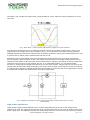
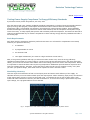
The graph in Fig. 2 depicts the output from a programmable ac source. Note the incoming waveform is a pure
sine wave.
Fig. 2. Power factor = cosine of phase angle between voltage and current waveform.
To make this measurement we use a wattmeter because it factors in the effect of power factor, cosine of the
angle between the voltage and current waveforms (cos φ). It is important to note that the energy efficiency
standard demands an input-power-measurement uncertainty of less than 2% for power measurements of 0.5 W
or greater and 10 mW for power measurements less than 0.5 W.
Wattmeters from several leading instrument manufacturers can be configured to meet these requirements.
Since a wattmeter features both a current- and voltage-sensing element, the voltage-sensing element can be
configured either before or after the input current-sense element. Typically, information on how to configure the
instrument can be found in its user manual. For low- or no-load measurements, you can achieve better
accuracy by configuring the voltage sense before the current-sense element. This prevents the current from the
voltage-sense element from being measured by the current-sense element. Given that the current consumed by
the voltage-sense element is typically greater than the allowable 10 mW at 230 Vac, this configuration is critical
to meeting the standard’s low measurement-uncertainty requirements.
Fig. 3. Wattmeter connections. Connect voltage sense before current sense for low or no-load
measurements.
High-Power Applications
Higher-power designs present different issues. In these applications the power loss in the voltage-sense
element is so small, the voltage-sense element can be connected after the current sense to locate it close to the
power supply input. This approach prevents the voltage drop across the current-sense element and the internal
© 2012 How2Power. All rights reserved.
Page 2 of 6