1
Section 5, 5-1
(5) Memory channels & banks
It is convenient to store commonly used frequencies into a memory channel along with mode etc, this
saves having to key the data in over and over again. Memory read is very straightforward and quick
when compared to re-typing all data.
5-1 Memory channel overview
Think of memory channels as pages in a notebook each of which is numbered to identify it. Data may be
written to each new page (memory channel) and each page may be overwritten with new data, they can
be used over and over again. The AR8200 has 1,000 memory channels in addition to 10 ‘quick
memory’ channels and a priority channel.
Each memory channel may hold:
l one frequency
l receive mode
l tuning step
l step-adjust
l frequency offset
l attenuator setting
l noise limiter status
l AFC status
l pass status
l write protect
l text comment of up to 12 characters
The alphanumeric comment may be used to ease identification at a later date and to provide text search
facilities.
The 1,000 memory channels are divided into 20 banks, each initially having 50 channels. The memory
banks are identified by letters A, B, C, D, E, F, G, H, I, J (upper case letters) and a, b, c, d, e, f, g, h, i, j
(lower case letters) and initially numbered from 00 to 49.
Examples are “A00” for the first channel location in memory bank “A” and “A49” for the last memory
channel in memory bank “A”. “e15” is the location of memory bank “e” (lower case) channel “15”.
During the manufacture and testing of the receiver, various test frequencies may be entered into the
receiver’s memory banks so the memory locations may not be completely blank.
&Note: Where memory channels and banks are empty the indication “- - -” is often displayed.
The stored data may be quickly and easily recalled, changed or deleted using the memory recall, edit
and delete facilities.
&Note:
It is suggested that one or two frequencies be held in each memory bank
to make the recalling and scrolling of memory banks fluent, if no data is stored, the
AR8200 may take up to 5 or 6 seconds to respond when attempting to change memory
bank while the CPU checks for data.
51
Section 5-1, 5-2
Auto-store
When shipped from the factory, memory bank “J” is reserved for auto-store of memory channels
from search mode. This is a useful facility to quickly build a list of active frequencies. Please refer
to section 8-7-5 of this manual for further information regarding AUTO-STORE.
Dynamic memory bank resizing
The lettered memory banks are regarded as a ‘pair’ making a total of 100 memory channels per bank,
initially equally divided between the upper and lower case letters. It is however possible to reallocate the
100 channels in blocks of 10 channels between the same letters A/a, B/b, C,c etc This means that the
initial 50/50 may be reallocated as 60/40, 70/30, 80/20, 90/10, or 10/90, 20/80, 30/70, 40/60. This
‘dynamic’ memory reallocation can be useful to optimise the memory layout where a large or small
collection of frequencies need to be monitored without unnecessarily wasting memory banks with just a
few channels occupied.
Write protect
It is possible to write protect individual memory channels to prevent accidental deletion, whole memory
banks and a ‘global’ write protect facility are also available.
Memory backup
The data contents of memory and search banks are held in an flash-ROM so that no backup battery or
capacitor is required for memory retention.
&Note: When the AR8200 is switched OFF, all VFO data will be automatically stored.
Should the NiCads (or dry batteries if in use) become completely exhausted, the last stored
memory channel or last VFO data ‘may’ be lost if the AR8200 is not powered-down using the
key and insufficient power is available to save the data.
5-2 Storing VFO frequencies & data into memory
It is possible to save frequencies to the ten quick memories for simple recalling but for longer-term
storage, the 1,000 main memory channels offer a better and more flexible system.
The process to save a displayed VFO frequency to memory is as follows:
a) In VFO mode, select the required frequency, mode, attenuator etc
to initiate memory write
b)
c) Use the keypad, main dial or ïðñò keys to select the desired memory location
(BANK and CHANNEL)
d) Add a text comment (optional) or delete an existing comment
e) Add memory channel write protect (optional)
f) Exit the menu to save the data to the specified memory location
Lets assume that you wish to store the frequency of 123.500 MHz
(with the attenuator off, noise limiter off, AFC off) into memory bank
“E” location “25” (E25) while in VFO mode with the text comment of
“AIRBAND”. If a mistake is made during programming,
the
key to abort entry and return to 2VFO mode.
a) Start by selecting VFO mode then key in the frequency of 123.500
MHz, “mode and step size” are set to the default auto “AUT” (if not
use the key sequence
52
)
Section 5-2
to place the AR8200 into VFO mode.
to select the desired frequency, the mode and step size will be automatically set by
the AR8200 microprocessor.
b)
the
key for more than one second to enter ‘memory input’ mode.
One line up from the bottom of the LCD will be the legend
“M-WRITE” with the highlight cursor positioned to the left of the
bank identification letter such as “j”. The microprocessor will
automatically select the youngest free memory location.
c) You may change the bank identifier at this time by pushing the
ï ð keys or by typing in a three digit memory location using the
numeric keypad.
You will notice that to the right of the keypad numbers, there are
small orange letters which are bank identifiers, available memory
locations are A - J and a - j. Key 1 is “A”, key 2 is “B” etc, ignore
the letters K - T as these are used in search mode only. The lower
case bank identifiers may be accessed pushing the CASE SHIFT
key
Remember, if you take too long entering data (90 seconds)
the display will revert to it’s original condition of 2VFO mode,
if you are selecting the memory location via a three digit
key sequence, you only have 2 seconds before the keypad
times-out!
Assuming that you wish to store 123.500 MHz into “E25”
to select bank “E” then select the channel,
for “25”. If any data is already stored
in location “E25”, the bottom line of the LCD will flash with the
stored frequency. You may accept & store the data (by pushing
or add a text comment at this point (see below).
d) To add the text comment “AIRBAND”,
ò then use the
main dial to select the text and the ï ð keys to move position of
text input.
A maximum of 12 characters may be added to each memory
channel, it is recommended that a minimum of three be used for
efficient use of the text search feature (a minimum of 2 characters
are required for text search). Refer to section 12 of this manual for
details of text search and section 13-2 for short cut text input).
53
Section 5-2, 5-2-1
If the memory location has been used previously and a text comment is displayed,
to
delete the existing comment.
&Note: It is possible to use keypad short cuts to select text characters, please refer to
section 13-2 of this manual for further details.
You may accept the new frequency and text comment “AIRBAND” by pushing
or you may add
memory channel write protect (see below).
e) To add the memory channel write protect,
off.
ò to access the “PROTECT” menu, the default is
to toggle the status to “ON”.
To accept the input and store the data to the specified location,
. The display will
revert to 2VFO mode.
&Important note: It is suggested that you do not use the write protect facility until you are
familiar with the operation of the AR8200 as it will prevent certain functions being carried out
at a future time.
5-2-1 Another example of memory write
Let’s assume that you wish to store the frequency of 433.000 MHz auto-mode into memory location
“d10” with the text comment of “70cm”.
a)
to place the AR8200 into VFO mode
to select the desired
frequency.
b)
to initiate ‘memory input’ mode.
c) Select the bank by pushing the ï ð keys and using the main dial for channel number, or by typing in
a three character memory address using the numeric keypad.
which acts as the CASE
Assuming that you wish to store 433.000 MHz into “d10”
SHIFT key to select the lower case banks then
select the channel
to select bank lower case “d”. Next
for “10”. If any data is already stored in location
“d10”, the bottom line of the LCD will flash with the stored frequency.
You need to carry out this key sequence fluently within 2 seconds or the bank location will time out.
The 2 second time out does not apply when the bank and channel are selected using the main dial
and ï ð keys.
54
Section 5-2-1, 5-2-2, 5-3
To recap:
Once the three digit memory location has been selected, the 2 second keypad time-out does not apply to
the rest of the sequence.
d) To add the text comment “70cm”,
ï ð keys to move position of text input.
ò then use the main dial to select the text and the
To accept the new frequency and text comment “70cm”,
, if you wish to add write protect
ò to access the PROTECT menu.
&Note: If the memory location has been previously used and a text comment is displayed,
to delete the existing comment.
e) In the write protect menu,
to toggle the status
to “ON”, the default is off.
To accept the input and store the data to the specified location,
. The display will revert to 2VFO mode.
5-2-2 Automatic memory allocation
When you
to start the memory write sequence, the AR8200 will initially offer the first
available empty memory location which has no data stored in it.
to accept the
channel offered or choose another location as described in the previous sections. Alternatively you may
the ò key to add a text comment then complete memory write by pushing
. If the
AR8200 has to look through many full memory channels before an empty channel is located, the
message “MEM WRITE SEARCH BLANK CH” may be briefly displayed.
5-3 Memory write protect
As indicated in section 5-2, it is possible to write protect memory contents to ensure that important
memory channels are not accidentally over-written. It is important to remember that by write protecting a
memory channel, it may prevent certain facilities from being used (such as over-writing the memory
channel or copying / swapping memory data to it).
The memory protect status may be assigned as the last stage of memory write (as per section 5-2 of this
manual) or toggled on/off using the memory channel EDIT facility, refer to section 9-6 of this manual
regarding memory channel EDIT facilities, in particular MEMORY PROTECT.
It is also possible to write protect a whole memory bank, this prevents accidental deletion of data when
resizing memory banks.
55
Section 5-3, 5-4
The memory bank write protect may be toggled on/off using the SCAN environment menu accessed by
followed by four pushes of the ò key.
the key sequence
to toggle bank select on/off and
the
to accept the changes and exit the menu.
Please refer to section 7-8-6 of this manual for details on MEMORY BANK write PROTECT.
&Note: Memory channel write protect prevents accidental over-writing and deletion of specific
memory channels but does not prevent loss of data due to memory resizing or when using the
optional external memory slot card.
5-4 Memory read “M.RD”
Once frequency and mode data has been stored into a memory location, its retrieval is quick and simple.
Let’s assume that you wish to retrieve the frequency of 123.500 MHz which has been programmed into
to memory “E25” during an earlier example in the preceding section 5-2 of this manual.
to place the receiver into memory read mode, the legend “M.RD” appears toward the
top left of the LCD to confirm operation. The AR8200 will monitor whatever memory channel first appears
when you enter memory read.
The AR8200 will display memory channel, mode, frequency, tuning step, text comment (if one was used),
attenuator status, noise limiter status and AFC status. The memory channel last used (for memory write
or recall) will initially be displayed, If the desired memory channel is not immediately displayed it may be
recalled by keying in the required three digit location.
To recall memory channel “E25”
(there is no need to push enter).
The “BANK/CH SEL” legend automatically appears
when the first key is pushed to remind you that you
are recalling memory channels in memory read
mode. Keypad memory recall requires a three digit
location, one letter for the bank and two numbers for
the channel. If you hesitate for more that 2 seconds
while recalling memory channels via the keypad the
sequence will time out, for more leisurely memory
recall use the ï ð ñ ò keys.
To recall memory “b06” the CASE SHIFT key needs to be used to access the lower case bank,
(there is no need to push
enter). If you attempt to recall a memory which has no valid data (because it is blank) the next valid
memory channel will be displayed instead. Blank memory channels are ignored.
56
Section 5-4-1, 5-5
5-4-1 Memory channel review / hunt
From VFO mode
to enter memory read “M.RD” mode.
The main dial may be rotated or the ñ ò keys pushed to review, hunt for and select memory channels
one by one, channels with no data stored will be skipped.
the ï ð keys to move between
memory banks one by one.
&Important note: It is suggested that each memory bank be programmed with at least one
memory channel otherwise the AR8200 may appear slow or sluggish when recalling banks
as the CPU has to check all memory channels for valid data, this is particularly noticeable if
jumping between bank “A” and “j” (opposite ends of the AR8200 memory map).
Memory read using the main dial and ï ð ñ ò keys is useful for reviewing memory contents and
hunting for a specific channel if you forget where you stored it! Should you know the number of the
required memory channel, the keypad method of memory recall will be much faster. The AR8200 will
monitor whichever memory channel is displayed in memory read “M.RD” mode.
It is also possible to hunt for memory channels using the TEXT SEARCH facility, please refer to
section 12-2 of this manual for further details.
5-5 Deleting memory channels
It is possible to over-write a memory channel with new data, edit the contents of a memory channel or
delete the channel entirely. When in memory read mode, use the key sequence
to access the “MEM DELETE” menu. The LCD menu invites you to “PUSH ENTER”
to delete the current memory channel,
to delete it or
to abort.
When deleted, the AR8200 increments to the next memory channel which contains data. It is also
possible to delete whole memory banks in one go using the DELETE menu. Please refer to the
section 10-3 of this manual relating to memory bank DELETE options.
57
Section 5-5-1, 5-5-2, 5-6, 5-7
5-5-1 Memory channel editing
It is possible to copy, move, swap and edit memory channels to assist the management of data.
Please refer to section 9 of this manual regarding the EDIT menu.
5-5-2 Adding text names to memory banks
To assist with memory management and identification, memory banks can be named. The SCAN BANK
menu is used to add or edit memory bank names.
To access the SCAN BANK menu
. The LCD will initially display the
legend “M-BANK”, the currently selected memory bank ‘pair’ (i.e. D/d or A/a or C/c etc) and the current
size allocation for the bank displayed i.e. B:50 b:50 for memory bank “B/b” with the allocation of 50
channels for “B” and 50 channels for “b”, this split of 50/50 being the default.
Use the main dial, ï ð keys or numeric keypad to select the required bank you wish to add a name to.
the ò key to move to the “BANK TEXT” menu.
Use the ñ ò keys to move between upper and lower bank identifiers, add text using the main dial and
ï ð keys or use the keypad. To save the data and exit the menu
.
5-6 Transfer of memory channel to VFO
While in memory read, should you wish to tune away from the memory channel and benefit from not
having to re-enter the frequency, mode etc, the data may be quickly transferred from memory to ‘VFO’
mode.
To transfer memory channel data to VFO simply
. The LCD will display the legend
“VFO” along with receive frequency, receive mode, tuning step size and other relevant information such
as attenuator, noise limiter and AFC status. You may monitor the frequency or tune away from it using
the main dial or ï ð ñ ò keys.
5-7 Dynamic memory bank resizing
The lettered memory banks are regarded as a ‘pair’ making a total of 100 memory channels per bank,
initially equally divided between the upper and lower case letters. For example memory bank “A” will
have 50 channels numbered from 00 to 49 (A00 - A49) and memory bank “a” will also have 50 channels
numbered from 00 to 49 (a00 - a49) making a total of 100 channels.
It is possible to reallocate the 100 channels in blocks of 10 channels between the same letters A/a, B/b,
C,c etc This means that the initial 50/50 may be reallocated as 60/40, 70/30, 80/20, 90/10, or 10/90,
20/80, 30/70, 40/60. This ‘dynamic’ memory reallocation can be useful to optimise the memory layout
where a large or small collection of frequencies need to be monitored without unnecessarily wasting
memory banks with just a few channels occupied.
The SCAN BANK menu is used to customise many features including memory bank resizing.
To access the SCAN BANK menu
58
.
Section 5-7, 6
The LCD will initially display the legend “M-BANK” , the currently
selected memory bank ‘pair’ (i.e. D/d or A/a or C/c etc) and the
current size allocation for the bank displayed i.e. A:50 a:50 for
memory bank “A/a” with the allocation of 50 channels for “A” and
50 channels for “a”, this split of 50/50 being the default. Use the
main dial, ï ð keys or numeric keypad to select the required
bank for resizing.
the ò key to move to the
“BANK TEXT” menu where a text comment may be added
(optionally) to ease identification of each bank (use the ñ ò keys
to move between upper and lower bank identifiers).
the ò key to move on to the resizing menu. The LCD will display the upper and lower case
identifiers on the same line with the current default allocation of 50/50 channels per bank. Use the main
dial or ï ð keys to reallocate the channels in increments of 10 channels (60/40, 70/30, 80/20, 90/10, or
10/90, 20/80, 30/70, 40/60).
&Note:
If you resize a memory which currently contains 50 channels to a new size of 10
channels, the last 40 channels will be deleted and data will be lost! Potentially when you resize
memory banks, programmed data may be lost so it is suggested that you carefully organise
your memory data before resizing memory channels. Individual memory channel protect will be
ignored but if a whole memory bank is protected, resizing will be inhibited.
After selecting the resizing value
ò to display the memory sorting menu, the legend
“MEM SORTING” will be displayed, the following lines confirm the current and proposed memory bank
sizes.
to initiate the resizing process. The LCD will clear except for the words
“MEM SORTING !!” with the exclamation marks flashing to indicate that the sorting process is in
operation… this can take several minutes depending upon the amount of data held in memory.
After sorting, the display returns to its previous condition (before the SCAN BANK menu was accessed).
&Important note: Memory sorting can take several minutes, do not switch the AR8200 off,
disconnect power, remove batteries or allow the batteries to fail during memory sorting or data
corruption may occur.
(6) Priority operation
The PRIORITY feature enables you to carry on scanning, searching or monitoring while the AR8200
checks a frequency taken from one of the 1,000 memory channels (A00 default) every 5 seconds
(default) for activity.
The priority checking is accomplished by momentarily moving to the priority frequency to see if it is
‘active’. If activity is found, the receiver remains on the frequency until the signal disappears. If no
activity is detected, the receiver returns to the VFO frequency, scan channel or search bank from where it
originated. The priority facility has a large number of applications and is particularly useful for keeping an
eye on a distress frequency while scanning or searching another frequency band.
&Note: Depending upon the frequency and mode stored as priority, an audible
‘click’ may be heard when the priority facility is in operation. This is quite normal and
is caused by the internal switching of circuitry necessary to accomplish the frequency
change as two frequencies cannot simultaneously be monitored by the receiver.
59
Section 6, 6-1, 6-2
&Note: The priority mode is automatically suspended during entry of frequencies via the
keypad, this prevents the receiver from changing frequency while you are busy programming.
Priority operation is disabled when the band scope is in operation.
6-1 Engaging PRIORITY channel
Once engaged, the default channel used for PRIORITY is “A00” and the frequency contained is checked
for activity every 5 seconds.
First ensure that there is data stored in memory channel “A00”.
To engage the priority facility
, this may be carried out while in SCAN,
SEARCH or VFO modes. The legend “PRI” is displayed in the top left hand corner of the LCD to indicate
that PRIORITY IS ENGAGED (switched on).
If activity is encountered on the priority channel, the AR8200 will stay on the priority frequency until the
transmission ends (and the squelch closes) after which time the priority frequency will be checked for
activity every few seconds.
&Note: Once priority has been activated, the data contents of the memory channel used
(default A00) may be altered without affecting the data used for PRIORITY operation which is
stored separately and assumes an identity of its own irrespective of the data contents of memory
A00.
Should you subsequently wish to alter the priority data, you
will have to use the “PRIO SET” menu detailed in section 6-2-1
of this manual.
To cancel priority operation
(which
acts as a toggle), the legend “PRI” will be removed from the LCD.
6-2 Changing PRIORITY channel data
The default channel used for PRIORITY is “A00” and the frequency copied from this channel is checked
for activity every 5 seconds. You may select a different memory channel from which the data will be
copied or may vary the sampling time for priority activity checking.
60
Section 6-2, 6-2-1, 6-2-2
This is accomplished by using the “PRIO SET” menu accessed by
the key sequence
.
The legend “PRIO SET” appears on the top line of the LCD to
confirm selection.
6-2-1 Changing the priority channel data pickup channel
Should you wish the priority channel to use data contained in another memory location, access the
“PRIO SET” menu using the key sequence
, the legend “PRIO SET”
appears on the top line of the LCD to confirm selection.
Select the new location for data pickup by the priority channel, use the main dial to move through the
memory locations one at a time or use the ï ð keys to move between banks, alternatively quickly key in
a three digit memory location via the keypad.
For example, select memory location “A23” using the key sequence
.
The priority interval time menu may be accessed using the ò key or
to exit the menu.
The newly nominated channel data will be used for priority monitoring.
&Note: If you attempt to nominate a channel which contains no data, the input will be
ignored and the previously used data will continue to be employed.
6-2-2 Changing priority interval time
Should you wish to check the priority frequency more or less often, the sampling time (interval) may be
set using the “PRIO SET” menu. Use the key sequence
“PRIO SET” menu.
to access the
the ò key to move the cursor to the “INTERVAL” input line.
Use the main dial to vary the interval time in increments of 1 second, the ï ð keys may be used to vary
the interval time in increment of 10 seconds. Priority time may be varied between the range of 1s to 99s.
the
key to act as a short cut to 5 seconds (default).
The more often you check the priority channel, the greater chance you have of ‘catching’ activity,
however the greater the interruption to normal monitoring.
to accept the input and exit the menu.
&Note:
Priority interval time is also used for VFO SCAN timings.
61
Section 7, 7-1, 7-2
(7) SCAN - scanning memory channels & banks
The AR8200 has a SCAN mode whereby the contents stored in the MEMORY CHANNELS ARE
AUTOMATICALLY RECALLED AND MONITORED very quickly for activity - scanned.
* It is important that you do not confuse SCAN and SEARCH modes. *
SEARCH mode (covered later in this manual) automatically TUNES THE RECEIVER
THROUGH ALL FREQUENCIES between two specified frequency limits
looking for active frequencies.
7-1 SCAN - outline introduction
During SCAN, the AR8200 automatically recalls each memory channel which contains data in numeric
order and monitors it looking for activity. When an ‘active’ memory channel is located (when a signal is
found and the squelch is open) the AR8200 will temporarily stop scanning.
At default when shipped from the factory, the AR8200 will remain on the active memory channel until
the received signal disappears and the squelch closes. The CPU will then wait a further 2 seconds in
case a reply is audible (such as aircraft and air traffic communications) and will then resume scanning
the memory channels again.
If the ñ ò keys are pushed or the main dial rotated (while scanning or when stopped on an active
channel), the receiver resumes scanning in the direction of the arrow key or rotation. This is particularly
useful for taking a second look a channels which have just been scanned.
Additional facilities available in SCAN
Memory banks may be “LINKED” and “UNLINKED” to effectively make larger or smaller groups of
memories which may be scanned together.
“PASS” may be used whereby memory channels can be skipped when not required (such as when
permanently busy), they may be easily reinstated at a later time.
“AUTO STORE” reserves memory bank “J” so that active frequencies found while conducting a
SEARCH may be automatically written to memory. This is a useful tool for compiling an activity list of
rarely used frequencies especially when unattended. Refer to section 8-7-5 of this manual for further
information relating to auto store.
It is possible to alter the sequence of scanning events using the SCAN ENVIRONMENT menu. There
are several scanning parameters which may be changed to suit your preferences and requirements
DELAY, LEVEL, VOICE, FREE & MODE, it is possible to mix combinations of all parameters.
7-2 SCAN considerations
It is presumed that you have already stored your favourite and commonly used frequencies into the
memory banks (as per section 5-2 of this manual).
A total of 1,000 memory channels are provided which are divided into 20 banks, each (at default) having
50 channels. The memory banks are identified by letters A, B, C, D, E, F, G, H, I, J (upper case letters)
and a, b, c, d, e, f, g, h, i, j (lower case letters) and numbered from 00 to 49.
62
Section 7-2, 7-3
When in SCAN MODE, the memory banks are referred to as “SCAN BANK A”, “SCAN BANK B”,
“SCAN BANK f” etc rather than using the full title “SCAN MEMORY BANK A”, “SCAN MEMORY BANK B”
etc. This terminology has been employed to make the explanation of and referral to SCAN MEMORY
BANKS (SCAN BANKS) less long-winded.
When shipped from the factory, memory bank “J” is reserved for auto-store of memory channels from
search mode so may already have frequencies stored.
Keep your memory banks tidy - for best scan speed
In order to achieve the maximum scanning speed, it is advisable to keep all similar frequencies and
modes grouped together within the memory banks. The greater the frequency change between memory
channels, then the further the receiver’s VCO (Voltage Controlled Oscillator) has to travel and the
slower the scan rates. Similarly, when many changes of mode are called, more switching has to be
accomplished and the scan speed may be reduced.
Memory channel data may be entered in duplicate into several channels. This will ensure the
channel data is scanned more frequently to increase the chances of activity being detected.
Limitations of SCAN mode
Should a number of different modes and wide range of frequencies be used, then the SCAN process
may be affected by noise or differences in squelch characteristic on some frequencies and modes.
To help provide the best operation of SCAN, additional facilities have been provided (configurable via the
SCAN ENVIRONMENT menu). Should you listen to noisy frequencies or bands containing carriers,
make liberal use of the AUDIO, LEVEL and FREE scan facilities.
7-3 Starting to SCAN
Presuming that some memory channels are programmed with data, to start the scan process will take
one or two pushes of the
key depending upon which operating mode is currently employed
(in VFO and search mode the first press accessed memory read):Memory read mode “M.RD”
VFO mode “VFO” or “2VFO”
Search mode “SRCH”
The legend “SCAN” is displayed toward the top left of the LCD to indicate that the SCAN process has
been started, a bank letter will also be displayed representing the current bank. Ensure that the
squelch control is advanced clockwise to threshold point so that background noise is cancelled
and the squelch closes (otherwise scan will not operate).
63
Section 7-3, 7-3-1, 7-4, 7-5
When SCAN has been selected, only the currently displayed memory bank WHICH CONTAINS DATA
will be SCANNED (as bank link is default off), receive mode and frequency are unimportant. Any
memory channels which contain no data (empty) will be ignored (skipped).
7-3-1 Transfer of active memory to VFO
When the scan process is paused on a busy channel,
to transfer the current memory
frequency to VFO where it may be monitored.
7-4 Selecting a scan bank
The memory bank identifier (such as “A”) will be
displayed on the left of the LCD under the legend
“SCAN”. If more than one memory channel is
programmed into the current memory bank the
channel numbers will be changing.
When an ‘active’ channel has been located (busy, so the
squelch opens) the scan process will
temporarily pause on the active channel, the memory
location (such as “A03”) will be displayed along with
any accompanying text (displayed underneath
the memory location).
To select another memory bank for
scanning, use the ï ð keys or
the corresponding letter on the
keypad from A to J, for lower case banks
the
CASE SHIFT
key first.
If no data is available,
the next bank with
valid data will be
recalled (empty
memory banks are
skipped).
To scan more that one
memory bank at a
time, please refer to
the scan bank linking
section 7-7 of this
manual.
7-5 Channel PASS
When scanning, you may encounter active memory channels which you do not wish to currently monitor.
It is possible to manually force the scan process to continue by pressing the
key or ñ ò keys
but this manual intervention can be an annoyance. For this reason it is possible to temporarily PASS
64
Section 7-5, 7-5-1, 7-5-2
unwanted channels so that they are skipped when scanning. PASS
does not delete the memory contents but simply ‘tags’ the channel
to be skipped. In memory read, the PASS tag may toggled on/off
and the tags removed in one operation using the delete pass
channel facility of the DELETE menu.
While paused (during scan) on a busy channel which you do not
currently wish to monitor,
to skip it. The scan
process will immediately move on to the next memory channel of
the current bank in the direction (up or down) which has been
previously used for tuning or memory read. This tagged memory channel will be skipped during
subsequent scans until the tag is removed. The legend “PAS” will have been assigned to the skipped
memory channel which may be reviewed in memory read mode.
7-5-1 Toggling memory channel PASS
The
key may also be used to tag (skip) unwanted channels when in memory
read. To cancel channel pass tag on a particular memory channel, recall it in memory
read mode then
. The LCD legend “PAS” indicates when the channel
is locked out, the
key toggles “PAS” on/off.
7-5-2 Removing ALL memory PASS tags in one go
It is possible to remove the memory PASS tags of ALL memory channels in all banks in one operation
using the DELET menu.
to access the DELETE menu.
the
ò key six times to display
the menu option “DEL MEM PASS”.
&Note: It will take a little while for the AR8200 to look for PROTECT channels and PASS
channels as you work through the menus.
If at least one memory channel has been tagged PASS, the third line from the bottom of the LCD will
display a memory location such as “PASS-CH A17” with the “A17” simply confirming that at least one
memory channel is tagged PASS. If no memory channels have been tagged PASS, the LCD will display
“PASS-CH ---”.
To remove all memory PASS tags in one go
, the legend “MEM PASS CH ALL OFF!!” will
be displayed to show that removal of pass tags is in process followed by “MEM PASS CH SEARCH !!” as
the AR8200 checks that all tags have been removed. The LCD will then display “PASS-CH ---” to
confirm that no channels are now tagged as PASS. To exit the menu and return to the standard display
.
65
Section 7-6, 7-6-1, 7-6-2, 7-7
7-6 Deleting memory channels
Although it is possible to over-write memory channels with new data, edit memory channels, swap, copy,
move and to PASS (skip) them, there will be occasions when you want to delete memory channels
completely.
7-6-1 Deleting single memory channels
While in memory read mode,
to delete the currently displayed memory
channel. As a safe guard against accidental deletion you will be instructed to
execute the deletion, alternatively
to
to abort delete.
Once memory channels have been deleted, the data is destroyed and cannot be recalled again.
7-6-2 Deleting whole memory banks in one go
Should you wish to delete the entire contents of a memory bank, the DELETE menu may be used, this is
quicker than recalling each memory in memory read mode and deleting them individually, especially if
there are more than about five or six channels involved.
the ò key three times to
to access the DELETE menu.
display the menu item “DELETE MEM-BANK B00”. The LCD will display a memory bank location such
as “MEM-BANK B00” with the “B00” being the last memory bank used. Use the ï ð ñ ò keys to select
the desired memory bank for deletion, alternatively type in the required bank letter via the keypad (the
CASE SHIFT key
will be required to access the lower case memory banks). If there are no
channels which contain data in the selected memory bank, the LCD legend “B --“ will be displayed with
“B” being the current bank and “--“ indicating that no channels are available for recall or scan (as they are
empty).
To delete all memory channels from the displayed bank
. After a few seconds the LCD
will display “DELETE MEM-BANK B--“ indicating that the selected bank no longer contains memory data.
.
To exit the menu and return to the standard display
7-7 Scan bank link (scan group)
It is possible to custom define scan parameters for a single bank
or group of memory banks.
Use the key sequence
to access
the “SCAN GROUP” menu. Bank “SCAN GROUP 0” contains a
default listing and cannot be overwritten (so displays “LINK OFF”
on the bottom line of the LCD), banks 1 to 9 are available for
custom programming.
Use the main dial or ï ð keys to select the SCAN GROUP
number, for SCAN-GROUP numbers 1 to 9 the legend
66
Section 7-7, 7-8
“BANK LINK” will be displayed on the bottom line of
the LCD indicating that programming is possible.
ò to move to the memory bank letters, then
reverse highlight the letters you wish to link together
as a group of memory channels to scan using the
ï ð ñ ò keys,
to mark desired
memory banks, both upper and lower case letters may
be highlighted in the same group. The selected banks
(which will form a large scan group) will be displayed
in REVERSE contrast on the LCD.
It is also possible to use the keypad to quickly select the required banks for inclusion as a group, this
saves having to use
to toggle selection, The CASE SHIFT key
is used to toggle
between the upper and lower case memory bank listings.
to accept the data input.
(one or twice) to start scanning if the
AR8200 is not already in scan mode. The memory banks grouped together in the SCAN GROUP will
form a large group during scan. The SCAN GROUP number (and associated data) will be used to define
current scan parameters.
For example: If you group banks “B, E, F, a, h” as SCAN GROUP number “1”, then when any one of
these banks is scanned, all other banks in the group will be scanned in sequence over and over…
B > E > F > a > h > B > E > F > a > h etc (providing each of the banks contains stored memory
channels).
It is possible to scan ANY memory bank, even if it is not contained in the current SCAN GROUP list by
manually selecting the bank using the ï ð keys or keypad while in scan mode.
You can individually configure each of the nine SCAN GROUPS
1 to 9 with a different collection of banks. SCAN GROUP 0
cannot be changed as it contains the default of LINK OFF so
that you can quickly disable bank link when individual memory
scan is required. SCAN GROUP 0 also contains default
settings for DELAY, LEVEL, VOICE, FREE and MODE
parameters.
To change the active SCAN GROUP, access the SCAN GROUP
menu using the key sequence
,
select the desired SCAN GROUP (0 to 9) using the main dial or ï ð keys then
to
accept the change and exit the menu.
7-8 Additional scan facilities
(Scan group environment - DELAY, LEVEL, VOICE, FREE, MODE)
It is possible to further customise the scan parameters for
each of the nine SCAN GROUPS (group 0 cannot be altered
as it contains the default information).
67
Section 7-8, 7-8-1, 7-8-2
Use the key sequence
to access the “SCAN-GROUP” menu. Use the
ï ð keys to select the SCAN-GROUP number between 1 and 9.
ò three times to move down
beyond the bank link facility and onto the additional scan environment facilities: delay, level, voice, free,
mode scan.
1.
DELAY
OFF / 0.1 - 9.9 seconds (default 2.0s)
2.
LEVEL
OFF / 1 - 255 (default OFF)
3.
VOICE
OFF / 1 - 255 (default OFF)
4.
FREE
OFF / 1 - 60 seconds (default OFF)
5.
MODE
ALL, WFM, NFM, SFM, WAM, AM, NAM, USB, LSB, CW
7-8-1 Scan DELAY
The scan DELAY parameter affects the time the AR8200 will remain on an active frequency in scan
mode once the received signal has disappeared and the squelch has closed. This is particularly useful
for customising how long the receiver will wait for a reply before resuming scan. For example, when
communications are passed back and forth between a control tower / aircraft which may take a few
seconds. The limits are OFF and 0.1 to 9.9 seconds in 0.1s increments (default 2.0 seconds).
Scan DELAY is configured via the SCAN-GROUP menu. Use the key sequence
to access the “SCAN-GROUP” menu. Use the ï ð keys to select the SCAN-GROUP
number between 1 and 9.
ò three times to display the scan environment parameters starting
with the DELAY.
to toggle the status between 2.0s and OFF,
the default is 2.0s. Use the main dial to increment delay time in
0.1s or the ï ð keys to increment in 1.0s.
2.0s
OFF
The AR8200 will wait the specified time after the
squelch closes before scan.
The AR8200 will resume scan instantaneously
when the squelch closes.
to accept the changes and return to the display prior to accessing the SCAN
environment menu. Alternatively you may move to the next option (scan LEVEL squelch) by pressing
the ò key.
7-8-2 Scan LEVEL
The scan LEVEL squelch parameter causes the AR8200 to check the signal strength and to only open
the squelch when the signal strength is above the stated level (which is programmable in 256 steps).
The limits are OFF and 1 to 255 (default off).
Scan LEVEL is configured via the SCAN-GROUP menu. Use the key sequence
to access the “SCAN-GROUP” menu.
68
Section 7-8-2, 7-8-3
ò four times to
Use the ï ð keys to select the SCAN-GROUP number between 1 and 9.
display the scan environment parameter of LEVEL.
as a short cut to off (which is the default). Use the main dial to increment value by
1 or use the ï ð keys to increment by 10.
While adjusting level squelch, the “¬” legend will be displayed to the left of the value “LEVEL
¬
3”
indicating that the current value will not cause the squelch to close. Increase the value until the “ ¬”
legend is just extinguished (this may typically be around a value of 120 - 230), the current transmission
and signals below this level will be skipped. There will be no audio produced when a transmission is
encountered below the level configured even though the “S” squelch legend is displayed. This is a
useful alternative to regular squelch on noisy bands such as short wave.
The approximate relationship between signal meter segments and level value is as follows:
1
2
3
4
5
6
7
124
141
154
168
178
185
193
8
9
10
11
12
13
14
200
203
206
208
210
212
214
&Note:
When level squelch is in operation, the rotary squelch control is usually best
rotated to the fully anti-clockwise position.
to accept the changes and return to the display prior to accessing the scan
environment menu. Alternatively you may move to the next option (scan VOICE squelch) by pressing the
ò key.
While scanning, the LCD legend “LSQ” is displayed to indicate that scan LEVEL squelch is in operation.
7-8-3 Scan VOICE
The scan VOICE squelch parameter causes the AR8200 to check the current frequency for valid audio
and to only open the squelch when audio above a specified level (which is programmable in 256 steps) is
detected. The limits are OFF and 1 to 255 (default off).
Scan VOICE is configured via the SCAN-GROUP menu. Use the key sequence
to access the “SCAN-GROUP” menu. Use the ï ð keys to select the SCAN-GROUP
number between 1 and 9.
ò five times to display the scan environment parameter of VOICE.
as a short cut to off (which is the default). Use the main dial to increment value by
1 or use the ï ð keys to increment by 10.
While adjusting voice squelch, the “¬” legend will be displayed to the left of the value “VOICE
¬
12”
indicating that the current value will not cause the squelch to close. Increase the value until the “ ¬”
legend is just extinguished (this may typically be around a value of 1 to 100), the current transmission
and signals with audio below this level will be skipped. There will be no audio produced when a
transmission is encountered with audio below the level configured even though the “S” squelch legend is
displayed.
69
Section 7-8-3, 7-8-4, 7-8-5
&Note: When voice squelch is in operation, the rotary squelch control is usually best rotated
to the fully anti-clockwise position.
to accept the changes and return to the display prior to accessing the scan
environment menu. Alternatively you may move to the next option (scan FREE time) by pressing
the ò key.
While scanning, the LCD legend “VSQ” is displayed to indicate that scan VOICE squelch is in operation.
7-8-4 Scan FREE
The scan FREE time parameter determines how long the AR8200 will remain on an active frequency
before resuming scan even though the frequency is still active. This is useful if you wish to gain a snap
shot of activity without the AR8200 being tied to a busy frequency for long periods of time (such as when
monitoring active amateur band repeaters etc). Scan FREE time saves you having to manually intervene
to force the scan process to resume and saves the need to lockout memory channels using the channel
PASS facility. The limits are OFF and 01 to 60 seconds (default OFF).
Scan FREE time is configured via the SCAN-GROUP menu. Use the key sequence
to access the “SCAN-GROUP” menu. Use the ï ð keys to select the
SCAN-GROUP number between 1 and 9.
ò six times to display the scan environment
parameter of FREE.
to toggle between OFF and 5 seconds (the default is off). Use the main dial to
increment value by 1s or use the ï ð keys to increment by 5s.
to accept the changes and return to the display prior to accessing the scan
environment menu. Alternatively you may move to the next option (scan receive MODE) by pressing
the ò key.
While scanning, the LCD legend “FRE” is displayed to indicate that scan FREE time is in operation and
the scan process will only pause on active frequencies for the specified time.
7-8-5 Scan (receive) MODE
The scan receive MODE parameter enables selected receive modes to be scanned in isolation even
though memory banks may contain many different receive modes. This saves the need to lockout
memory channels using the channel PASS facility when only a certain receive mode is desired (such as
AM for airband monitoring etc).
Scan receive MODE is configured via the SCAN-GROUP menu. Use the key sequence
to access the “SCAN-GROUP” menu. Use the ï ð keys to select the
SCAN-GROUP number between 1 and 9.
parameter of MODE.
70
ò seven times to display the scan environment
Section 7-8-5, 7-8-6, 7-9, 7-9-1, 7-9-2
as a short cut to ALL (which is the default) which will cause all receive modes to be
scanned in the specified scan group. Use the main dial or ï ð keys to select the receive mode:
ALL, WFM, NFM, SFM, WAM, AM, NAM, USB, LSB, CW.
to accept the changes and return to the display
prior to accessing the scan environment menu. The ò key loops
back to the top of the SCAN-GROUP menu.
While scanning, only memory channels with the corresponding
receive mode will be scanned. The legend “SCAN NFM” or
“SCAN AM” etc will be displayed indicating that only specific
modes will be scanned, the modes are displayed in REVERSE
CONTRAST highlighting. If no channel contained within the bank
group matches the specified receive mode, the scan will be
aborted and the display will return to 2VFO mode with an error
beep sounding (if the beep is enabled).
7-8-6 Write protect of memory channels & banks
It is possible to write protect memory channels, whole memory banks, search banks and ‘globally protect’
memory to prevent data being accidentally over-written. Refer to section 11 of this manual regarding the
write protect options.
7-9 Select scan
Select scan enables you to ‘tag’ memory channels to make a temporary list of up to 100 channels for
scanning in a separate list called the SELECT SCAN LIST. Memory channels from any of the 20
memory banks may be mixed together in any order and added to the select scan list.
7-9-1 Adding select scan channels in memory read
In memory read mode or when paused on an active channel in scan mode use the key sequence
to toggle the select scan tag on/off, the legend “SEL” confirms selection.
Even memories marked as channel pass may be added to the select scan list, the pass status will be
ignored by select scan.
7-9-2 Starting / stopping select scan
To start select scan you must first have at least two memory
channels tagged for select scan.
to start select scan. The legend “SEL” will be displayed on the left
hand side of the LCD to indicate that select scan is in progress.
The memory channels will be displayed as select scan progresses
and each memory channel will display the legend “SEL”. The
direction of scan can be reversed using the main dial or ñ ò keys.
To stop select scan,
or
or
71
Section 7-9-3, 7-9-4
7-9-3 Select scan environment
The select scan environment may be customised in respect of DELAY, LEVEL, VOICE, FREE and
MODE. The current SCAN-GROUP selection is used by select scan. To access the scan group
environment menu
. For further information regarding the scan group
environment please refer to section 7-8 of this manual.
7-9-4 Editing the contents of the select scan list
Although it is possible to review all 1,000 memory channels using memory read to assess which memory
channels are tagged for select scan, a quicker method is available via the select scan menu.
to access the “SEL-SCAN” menu.
One hundred select scan channels are available and numbered
from 00 to 99. Use the main dial or ï ð keys to scroll through the
select scan list contents. The select scan numbers are allocated in
the order in which they were tagged in memory read mode, the
memory bank/channel number, frequency and any text comment is
displayed.
Deleting singe select scan channels
To remove the displayed channel from the select scan list
. The frequency is removed
from display (“SEL” tag is removed from the memory channel) and the position in the select scan list will
be filled with the next highest select scan channel number. For example, if you have five select channels
listed and delete number “03”, channel number “04” will slide down to take its place
(any gap is filled) so that “04” will be renumbered as “03”, “05” will become “04” and so on.
Adding new select scan channels
It is possible to tag select scan memories in memory read mode, it is also possible to add additional
select scan channels using the select scan menu.
to access the select scan menu.
the ï key to wrap around to the end of the select scan
list, the legend “SEL-SCAN xx --- ----.---- ------------“ will be
displayed where “xx” is the next available select scan channel.
The ‘dashes’ indicate that the channel is currently unused.
ò to display the legend “BANK/CH SEL” inviting you to
select a memory channel to add to the select scan list.
Select the desired memory channel by keying a three digit location
via the keypad or scroll through the memory banks using the ï ð
keys and main dial to scroll through the memory channels.
to accept the displayed memory location to be
added to the select scan list. The memory data will appear alongside the select scan number.
72
Section 7-9-4, 7-9-5
ð once to move upward to the new end of the
If you wish to add more select scan channels
list and repeat the process.
or
to exit the select scan menu.
It is possible to delete the entire select scan list in one go using the DELETE menu, this is very useful to
enable rapid changes to the select scan list content.
7-9-5 Deleting all select scan channels
Although it is possible to review and delete select scan channels in memory read and by using the select
scan menu, a quicker method is available should you wish to delete all select scan tags in one go. This
is particularly useful when you wish to start a new select scan list (making the select scan list almost like
a note pad).
The DELETE menu is used to delete all select scan channels in one go. To access the delete menu
.
the ò key four times to display the “DELETE SEL-CH”
menu. If at least one select scan channel exists, a channel location will be displayed to the right of the
legend “SEL-CH Xxx” where “Xxx” represents the channel location, if no select scan channels exist the
legend “SEL-CH --” will be displayed.
to delete the select scan list, the “SEL-CH --“ legend confirms deletion.
or
or
or
or
to exit the delete menu.
&Note: Only the select scan ‘tags’ are deleted using this procedure, the memory channel
contents are not erased or altered in any other way.
73
Section 8, 8-1, 8-1-1
(8) Search mode
In search mode, the AR8200 is programmed to automatically tune between two specified frequency limits
looking for activity. Please refer to section 1-3 of this manual if you do not fully understand the
terminology of SEARCH.
8-1 Search types
The AR8200 is equipped with two types of search:VFO SEARCH = search from the current frequency in VFO mode.
Please refer to section 4-3 of this manual for further information.
PROGRAM SEARCH = search between user programmed limits.
8-1-1 Program search overview
There are 40 program search banks (referred to simply as search banks) which can be programmed with
specific parameters:
l LO (lower) start frequency
l HI (upper) stop frequency
l Receive mode (or set to AUTO MODE)
l Receive tuning step (or set to AUTO MODE)
l Step adjust
l Frequency offset
l Attenuator status
l Noise limiter status
l Text comment
l Write protect
l CTCSS tone (if the CT8200 SLOT CARD option is used)
The program search banks are identified by upper case letters A - T and lower case letters a - t. To help
with identification, each bank may be labelled with an alpha-numeric text comment.
74
Section 8-1-1, 8-2, 8-2-1, 8-2-2, 8-2-3
To assist testing in the factory, several search banks may be programmed with data (which can be easy
deleted or over-written). This pre-programming is useful to ease familiarisation during the early days of
operation… so that when you push a key there is something already programmed to work!
8-2 Starting program search
Presuming that data is already stored into a search bank…
the
key to start the program search
process. The LCD legend “SRCH” will be displayed and as
long as the squelch is closed, the search process will start
from the lower frequency limit and will progress toward the
upper frequency limit. When the program limit is reached,
the search loops around and starts the process again.
&Note: If no search banks have been
programmed, the search process will not operate.
8-2-1 Reversing the
direction of search
To reverse the direction of
search use the main dial
or ñ ò keys, this is useful
to enable you to search
back over and over an
interesting point of the
search process.
8-2-2 Forcing the search to resume
If the AR8200 stops on an unwanted busy frequency,
the
key or use the ñ ò keys or
main dial to force the search process to resume from the current frequency displayed.
8-2-3 Stopping the search
While the search process is in progress (not stopped),
to stop searching and transfer
the current frequency to the single VFO for monitoring or tuning from. To exit the search process
the
key for memory read mode or the
key for 2VFO mode (displaying the
data on-screen before search was started).
75
Section 8-2-4, 8-3
8-2-4 Copying an active frequency to the VFO or memory location
It is convenient to transfer an active frequency from search to VFO or memory for periods of extended
listening.
Copy to VFO
When the search process is stopped on an active frequency,
the
key to transfer the
current receive frequency to the single VFO where it may be monitored.
Write to memory
When the search process is stopped on an active frequency,
the
key to write the
current receive frequency into the first available empty memory location (or you may select a specific
location from the 1,000 memory channels available).
8-3 Selection of search bank
There are 40 search banks, while searching use the ï ð keys to step through search banks which
contain data, alternatively you may use the numeric keys (with assigned letters and shifts). If no data is
programmed in the nominated search bank, the next bank containing valid data will be used.
Recalling search banks A - J is very simple involving only one key push, for this reason it is suggested
that these banks are used for primary search tasks.
While searching,
the numeric key corresponding to the required search bank:
A*
B
C
D
E
F
G
H
I
J
* When bank “A” is selected via the keypad, a delay of around two seconds will be encountered before
the
key is acted upon, this is because the
status when selecting banks K - T and k - t.
Tip: to search “A” instantly,
76
key also has a special ‘SHIFT’ command
Section 8-3
Recalling banks K - T requires use of the ‘SHIFT’
command before the letter key, this ‘shift’
command is the use of the
Recalling banks k - t requires use of the ‘case’
and ‘shift’ command before the letter key:
key before a
second numeric key is pushed. You must key
quickly or bank “A” will be selected, the timeout
while using the ‘shift’ key is around two seconds:
k
l
m
K
n
L
o
M
p
N
q
O
r
P
s
Q
t
R
S
T
Recalling banks a - j requires use of the ‘CASE’
command before the letter key, this ‘case’
command (selecting upper or lower case bank
letters) is the use of the
key before a
second numeric key is pushed.
a
b
c
d
e
f
g
h
I
j
77
Section 8-4
8-4 Programming a search bank
Each of the 40 search banks may be programmed with
different frequency limits, receive modes, step size etc as
listed in section 8-1-1 of this manual.
to access the
“SRCH-PROG” menu.
Use the main dial or ï ð keys or keypad to select the
bank you wish to program or over write. (The ò key is
used to move through the menu).
ò
LO Input the lower start
frequency in MHz format
(don’t push enter)
ò
HI Input the higher end frequency in MHz format
(don’t push enter)
ò
MODE SET Use the ï ð keys or main dial to select receive
mode, the
key is used as a short cut to “AUTO”.
&Note: If the receive mode is set to “AUTO”, the receive mode,
channel step, step-adjust, frequency offset will be taken from the
pre-programmed auto band plan data, for this reason the
detailing will not be required while programming so is skipped…
the next menu will be TEXT INPUT.
ò
STEP Assuming that a receive mode other than “AUTO” was selected, you will be presented
with the “SET STEP” menu. Use the main dial or ï ð keys to select the required tuning step
from the following: 0.05 kHz (50 Hz), 0.1 kHz (100 Hz), 0.2 kHz (200 Hz), 0.5 kHz (500 Hz), 1.00
kHz, 2.00 kHz, 5.00 kHz, 6.25 kHz, 8.33 kHz, 9.00 kHz, 10.00 kHz, 12.50 kHz, 20 kHz, 25.00
kHz, 30 kHz, 50 kHz, 100.00 kHz. Alternatively a step size may be entered in kHz format via the
keypad in multiples of 50 Hz in the range of 50 Hz to 999.95 kHz (do not push enter).
78
Section 8-4
&Note: If a step-adjust value is already programmed into the search bank, the step-adjust
menu will be automatically displayed when accessing the step input menu.
STEP ADJ+ If you with to manually enter a step-adjust value for tracking unusual band plans
, the “STEP ADJ+” legend will be displayed.
ò to move the cursor
to the “ADJ+” line and enter a step-adjust value using kHz format (do not push enter). You can
use the ñ key in this menu to move back to STEP size selection.
&Note: Step-adjust value will be calculated automatically by the AR8200 if a manual entry is
not made. The CPU calculates if the selected tuning step size is divisible into the search bank
start and end frequency limits and sets step-adjust accordingly.
ò to access the TEXT INPUT menu.
TEXT The cursor will be positioned in the bottom left corner of the
LCD. If an unwanted text comment exists
to
delete the character
highlighted by the cursor
and the remainder of the line
to the right of the cursor
position. Add text if you
wish.
ò to access the PROTECT menu.
PROTECT It is possible to protect a search bank to prevent
accidental over-writing of data.
to toggle the
write protect status on/off (default is off).
To accept the data input
Alternatively
ò to return to the top of the menu or
.
to abort. The
LCD will revert to its previous display (VFO, search or scan mode).
To start SEARCH
, use the ï
ð
keys or keypad to select search bank.
The attenuator, noise limiter or AFC can be toggled
on/off during the search process.
79
Section 8-5, 8-5-1
8-5 Locking out unwanted active frequencies (PASS)
It is possible to lock out (PASS) unwanted frequencies while in program search mode,
this is useful to eliminate unwanted permanent transmissions. It is important to
understand the PASS facility before using the
key or transmissions may be
missed.
, the search process will resume. It will
While stopped on an unwanted frequency
appear that all frequencies are still searched, however locked out frequencies will be ‘passed over’, the
search will not stop on locked out frequencies but the squelch may momentarily open causing a short
burst of audio before the frequency is passed… if several consecutive active frequencies are locked out,
an audio ‘chuff… chuff… chuff…’ may be encountered.
Locked out PASS frequencies are assigned PASS CHANNEL NUMBERS, there are a total of 50 PASS
channels for each search bank. Frequencies ± 10 kHz from the assigned pass frequency will be
skipped, carefully consider the implications of locking out ± 10 kHz when using USB, LSB and CW.
When you attempt to exceed the limit of 50 pass channels per bank an error beep will be emitted (if beep
is enabled). The locked out frequency will be relevant to the current search bank only… i.e. if you lock
out 124.500 MHz in search bank “A”, this frequency will not be locked out of any other search bank and
may be searched as usual in any other bank.
8-5-1 Search pass menu
It is possible to review, delete and add pass channels using the SEARCH PASS menu.
If you are currently searching
, the “SRCH PASS” menu will be displayed along with
current bank letter.
From any other point
will be displayed,
, the VFO-PASS menu
ò to access the “SRCH PASS”
menu, use the ï ð keys at display the desired search bank
letter.
If pass channels have already been tagged for the current search
bank the legend “PASS xx” will be displayed where “xx” indicates
that data is present. If no pass frequencies have been tagged,
the legend “PASS 00 ----.----” will be displayed.
The ï ð keys, main dial or keypad may be used to change
search bank.
the ò key to access the review section of
the menu, the frequency pass contents of the displayed bank
may be reviewed using the ï ð keys or main dial.
To delete the displayed pass frequency key in a nul value
(0 = zero)
. The frequency pass
channel will be deleted and the list will re-shuffle. The frequency is once again available in search mode.
80
Section 8-5-1, 8-6
To delete the entire contents of the current search pass list
, the legend
“PASS 00 ----.----” confirms deletion. The search pass list may also be deleted using the DELETE menu,
refer to section 10-1 of this manual.
Adding new pass frequencies
Access the search pass list, If you are currently searching
, the “SRCH PASS” menu will be displayed
along with current bank letter. From any other point
, the VFO-PASS menu will be displayed,
ò to access the “SRCH PASS” menu, use the
ï ð keys at display the desired search bank letter.
the ð key to wrap around to the end of the pass
frequency list, the legend “PASS xx ----.----” will be displayed
where “xx” is the next available frequency pass channel. The
‘dashes’ indicate that the channel is currently unused.
Key in a frequency which you wish to skip during search of the
current bank using MHz format and ending with
.
the ð key and repeat the process if you wish to add
further frequencies to be skipped. To accept the data entry and
exit the menu
. This facility is particularly useful if you know what frequencies are
unwanted prior to searching, such as constant carriers etc.
&Note:
You may add frequencies in the range of 100 kHz to 2400 MHz via this menu but
only those within the current search limits will be acted upon.
It is also possible to delete the entire frequency pass list using the DELETE menu, refer to section 10-1
of this manual.
8-6 Search bank link
It is possible to custom define search parameters for a single bank or group of search banks.
Use the key sequence
to access the “SRCH GROUP” menu. Bank
“SRCH GROUP 0” contains a default listing and cannot be overwritten (so displays “LINK OFF” on the
bottom line of the LCD), banks 1 to 9 are available for custom programming.
Use the main dial or ï ð keys to select the SEARCH GROUP number, for SEARCH GROUP numbers
1 to 9 the legend “BANK LINK” will be displayed on the bottom line of the LCD indicating that
programming is possible.
ò to move to the search bank letters A - T and a - t, use the ñ ò keys to move between upper
and lower case letters.
81
Section 8-6, 8-7
Next reverse highlight the letters you wish to link together as a group using the ï ð ñ ò keys,
to mark the desired search banks, both upper and lower case letters may be
highlighted in the same group. The selected banks (which will form a large group) will be displayed in
REVERSE contrast on the LCD.
It is also possible to use the keypad to quickly select the required banks for inclusion as a group, this
saves having to use
to toggle selection, The CASE SHIFT key
between the upper and lower case and the SHIFT key
is used to toggle
is used to access letters between
K - T and k - t.
to accept the data input.
to start searching (if the AR8200 is not already in search mode). The banks grouped
together in the SERACH GROUP will form a large group during search. The SEARCH GROUP number
(and associated data) will be used to define current program search parameters.
For example: If you group banks “A, B, E” as SCAN GROUP number “1”, then when any one bank is
searched, all other banks in the group will be searched in sequence over and over… A > B > E > A > B >
E > A > B > E etc (providing each of the banks contains search program data).
It is possible to search ANY bank, even if it is not contained in the current SEARCH GROUP list by
manually selecting the bank using the ï ð keys or keypad while in search mode.
You can individually configure each of the nine SEARCH GROUPS 1 to 9 with a different collection of
banks. SEARCH GROUP 0 cannot be changed as it contains the default of LINK OFF so that you
can quickly disable bank link when you wish to search only one bank. SEARCH GROUP 0 also contains
default settings for DELAY, LEVEL, VOICE and FREE parameters.
To change the active SEARCH GROUP, access the SEARCH GROUP menu using the key sequence
, select the desired SEARCH GROUP (0 to 9) using the main dial or ï ð
keys then
to accept the change and exit the menu.
8-7 Additional search facilities
(Search group environment - DELAY, LEVEL, VOICE, FREE, AUTO STORE, DELETE J).
It is possible to further customise the search parameters for each of the nine SEARCH GROUPS
(group 0 cannot be altered as it contains the default information).
Use the key sequence
to access the “SRCH-GROUP” menu. Use the
ï ð keys to select a SRCH-GROUP number between 1 and 9.
ò five times to move down
beyond the bank link facility and onto the additional search environment facilities: delay, level, voice,
free, auto store and delete J.
82
Section 8-7, 8-7-1
1.
DELAY
OFF / HOLD / 0.1 - 9.9 seconds (default 2.0s)
2.
LEVEL
OFF / 1 - 255 (default OFF)
3.
VOICE
OFF / 1 - 255 (default OFF)
4.
FREE
OFF / 1 - 60 seconds (default OFF)
5.
AUTO STORE
ON / OFF (default OFF)
6.
DELETE J
Yes / No (using
key)
8-7-1 Search DELAY
The search DELAY parameter affects the time the AR8200 will remain on an active frequency in search
mode once the received signal has disappeared and the squelch has closed. This is particularly useful
for customising how long the receiver will wait for a reply before resuming search. For example, when
communications are passed back and forth between a control tower / aircraft which may take a few
seconds. The limits are OFF / HOLD and 0.1 to 9.9 seconds in 0.1s increments (default 2.0 seconds).
Search DELAY is configured via the SRCH-GROUP menu. Use the key sequence
to access the “SRCH-GROUP” menu. Use the ï ð keys to select the SRCH-GROUP
number between 1 and 9.
ò five times to display the search environment parameters starting
with the DELAY.
to toggle the status between 2.0s / HOLD / OFF, the default is 2.0s. Use the main dial
to increment delay time in 0.1s or the ï ð keys to increment in 1.0s.
2.0s
HOLD
OFF
The AR8200 will wait the specified time after the squelch closes before
resuming search.
The AR8200 will stop indefinitely when an active frequency is located, this is
very useful when you don’t want to miss that once-in-a-lifetime transmission!
The AR8200 will resume search instantaneously when the squelch closes.
to accept the changes and return to the display prior to accessing the SEARCH
environment menu. Alternatively you may move to the next option (search LEVEL squelch) by pressing
the ò key.
83
Section 8-7-2, 8-7-3
8-7-2 Search LEVEL
The search LEVEL squelch parameter causes the AR8200 to check the signal strength and to only open
the squelch when the signal strength is above the stated level (which is programmable in 256 steps).
The limits are OFF and 1 to 255 (default off).
Search LEVEL is configured via the SRCH-GROUP menu. Use the key sequence
to access the “SRCH-GROUP” menu. Use the ï ð keys to select the SRCH-GROUP
ò six times to display the search environment parameter of LEVEL.
number between 1 and 9.
as a short cut to off (which is the default). Use the main dial to increment value by 1
or use the ï ð keys to increment by 10.
While adjusting level squelch, the “¬” legend will be displayed to the left of the value “LEVEL
¬
3”
indicating that the current value will not cause the squelch to close. Increase the value until the “¬”
legend is just extinguished (this may typically be around a value of 120 - 230), the current transmission
and signals below this level will be skipped. There will be no audio produced when a transmission is
encountered below the level configured even though the “S” squelch legend is displayed. This is a
useful alternative to regular squelch on noisy bands such as short wave.
The approximate relationship between signal meter segments and level value is as follows:
1
2
3
4
5
6
7
8
9
10
11
12
13
14
124
141
154
168
178
185
193
200
203
206
208
210
212
214
&Note: When level squelch is in operation, the rotary squelch control is usually best rotated
to the fully anti-clockwise position.
to accept the changes and return to the display prior to accessing the search
environment menu. Alternatively you may move to the next option (search VOICE squelch) by pressing
the ò key.
While searching, the LCD legend “LSQ” is displayed to indicate that search LEVEL squelch is in
operation.
8-7-3 Search VOICE
The search VOICE squelch parameter causes the AR8200 to check the current frequency for valid audio
and to only open the squelch when audio above a specified level (which is programmable in 256 steps) is
detected. The limits are OFF and 1 to 255 (default off).
Search VOICE is configured via the SRCH-GROUP menu. Use the key sequence
to access the “SRCH-GROUP” menu. Use the ï ð keys to select the SRCH-GROUP
number between 1 and 9.
VOICE.
84
ò seven times to display the search environment parameter of
Section 8-7-3, 8-7-4
as a short cut to off (which is the default). Use the main dial to increment value by 1
or use the ï ð keys to increment by 10.
While adjusting voice squelch, the “¬” legend will be displayed to the left of the value “VOICE
¬
12”
indicating that the current value will not cause the squelch to close. Increase the value until the “ ¬”
legend is just extinguished (this may typically be around a value of 1 to 100), the current transmission
and signals with audio below this level will be skipped. There will be no audio produced when a
transmission is encountered with audio below the level configured even though the “S” squelch legend
is displayed.
&Note:
When voice squelch is in operation, the rotary squelch control is usually best rotated
to the fully anti-clockwise position.
to accept the changes and return to the display prior to accessing the search
environment menu. Alternatively you may move to the next option (search FREE time) by pressing
the ò key.
While searching, the LCD legend “VSQ” is displayed to indicate that search VOICE squelch is in
operation.
8-7-4 Search FREE
The search FREE time parameter determines how long the AR8200 will remain on an active frequency
before resuming search even though the frequency is still active. This is useful if you wish to gain a snap
shot of activity without the AR8200 being tied to a busy frequency for long periods of time (such as when
monitoring active amateur band repeaters etc). Search FREE time saves you having to manually
intervene to force the search process to resume and saves the need to lockout (PASS) busy frequencies.
The limits are OFF and 01 to 60 seconds (default OFF).
Search FREE time is configured via the SRCH-GROUP menu. Use the key sequence
to access the “SRCH-GROUP” menu. Use the ï ð keys to select the SRCH-GROUP
number between 1 and 9.
ò eight times to display the search environment parameter of
FREE.
to toggle between OFF and 5 seconds (the default is off). Use the main dial to
increment value in by 1s or use the ï ð keys to increment by 5s.
to accept the changes and return to the display prior to accessing the search
environment menu. Alternatively you may move to the next option (AUTO STORE) by pressing
the ò key.
While searching, the LCD legend “FRE” is displayed to indicate that search FREE time is in operation
and the search process will only pause on active frequencies for the specified time.
85
Section 8-7-5, 8-7-6
8-7-5 AUTO STORE
Auto store causes the first 50 active frequencies located during search to be automatically written to
memory bank “J” (channels J00 to J49). If bank “J” is full, auto store will not function.
&Note: Memory banks are dynamically configurable so that bank “J” has 50 channels at
default buy may be configured to provide 10, 20, 30, 40, 50, 60, 70, 80, or 90 channels.
Refer to section 5-7 of this manual regarding dynamic memory bank resizing.
Search auto store is configured via the SRCH-GROUP menu. Use the key sequence
to access the “SRCH-GROUP” menu. Use the ï ð keys to select the SRCH-GROUP
number between 1 and 9.
ò nine times to display the search environment parameter of AUTO
STORE.
to toggle between OFF and ON (the default is off).
to accept the changes and return to the display prior to accessing the search
environment menu. Alternatively you may move to the next option (DELETE J) by pressing the ò key.
While searching, the LCD legend “AS” is displayed to indicate that auto store is in operation.
Frequencies closer than ± 10 kHz to a frequency already stored in bank “J” will be ignored, this prevents
the same frequency being stored over and over again. As busy frequencies are located and entered
automatically into memory bank “J”, any associated search bank text comment will also be stored into
memory to help identify from which search bank the frequencies originated.
8-7-6 DELETE bank “J”
To simplify the VFO auto store feature, it is possible to delete the contents of memory bank “J” using this
menu… this allows you to quickly ‘dump’ the unwanted contents of the auto store memory bank “J”
before starting a new search with the auto store feature enabled.
‘DELETE J’ is configured via the SRCH-GROUP menu. Use the key sequence
to access the “SRCH-GROUP” menu. Use the ï ð keys to select the SRCH-GROUP
number between 1 and 9.
ò ten times to display the search environment parameter of
DELETE J.
If bank “J” contains data, the legend “J00” will be displayed, if no data is held in bank “J” the legend “J --”
will be displayed.
to delete the contents of bank “J”, this will take a few sections to
action by the CPU. The legend “J --” will be displayed to confirm deletion.
to return to the display prior to accessing the VFO environment menu.
86
Section 8-7-7, 8-7-8
8-7-7 Deleting search banks
A delete menu is provided so that you can delete program search data (of course you may simply
over-write the data too) and frequency pass channels. You cannot delete search banks which have been
write protected.
While in search mode, the DELETE menu is accessed using the key sequence
. (While in SCAN or VFO mode use the key sequence
and use ï ð to select the required search
bank).
The “HI” and “LO” frequency limits will flash on the LCD along
with any associated text comment to aid the identification of the
required search bank. To delete the program search data
, the legend “----.----” confirms data deletion.
to exit the menu returning to the standard
display, alternatively
ò to move to the “DEL PASS” selection point.
When deleting program search data, the associated FREQUENCY PASS channels are not deleted
just in case you wish to go back to the same programming at a later data, after all they will be ignored if
a different frequency range is programmed into program search for this bank. With this in mind, you
may leave regularly used pass frequencies relating to several frequency ranges in the bank to save
reprogramming at a later date when different program search ranges are used (there are a total of 50
pass frequencies per bank and are only acted when searching the current bank).
If frequency pass channels exist for the current bank, the legend “DEL PASS xx” will be displayed with
the “xx” number (00 to 49) indicating that data is present. If no data is present the legend “DEL PASS --”
will be displayed. To delete the frequency pass data
, the legend “DEL PASS --”
confirms deletion.
to exit the menu returning to the standard display.
8-7-8 Write protect and copying search banks
It is possible to write protect search banks to prevent accidental
deletion of stored data, this is accomplished using the EDIT menu.
It is also possible to copy search data from one bank to another
using the same menu. Refer to sections 9-7 & 9-3 of this manual
regarding the write protect and copy options.
87
Section 9, 9-1
(9) EDIT menu
The EDIT menu is a powerful feature which simplifies the management of data and provides the
following operations:
COPY MEM-CH
loads one memory channel to save to another location
COPY MEM-BNK
loads one whole memory bank to save to another location
COPY SEARCH
loads one search bank to save to another location
MOVE MEM-CH
loads one memory channel to save to another location
leaving the original memory location blank
SWAP MEM-CH
swaps the data of two memory channels with each other
EDIT MEM-CH
enables the contents of a memory channel to be changed
including mode, step, frequency, text comment and write
protect
MEM PROTECT
enables you to toggle the write protect status of memory
channels
SRCH PROT
enables you to toggle the write protect status of search
banks
The edit menu is called with the key sequence
9-1 EDIT COPY memory channel
The COPY MEMORY CHANNEL menu enables you to make an exact copy of one memory bank into
another bank location, the original memory bank is left intact and completely unaffected. Due to dynamic
memory bank resizing, it is possible that the highest channel number in any memory bank could be in the
range of 09 to 89 (default is 49).
The “COPY MEM-CH” menu is accessed using the key sequence
Two data input lines are presented LOAD and SAVE.
The cursor will be positioned on the LOAD line. “LOAD”
represents the memory channel which you would like to make a
copy of (this is the data you want). Use the main dial to select
channel number and the ï ð keys to select bank, alternatively
type in a three digit memory location via the keypad.
ò to move to the SAVE line.
“SAVE” is the target
memory location where data is to be written. Use the main dial to
select channel number and the ï ð keys to select bank,
alternatively type in a three digit memory location via the keypad.
to copy the memory channel data to the target location. Both LOAD and SAVE
displayed memory channel locations revert to LOAD location.
The process may be repeated for other locations.
88
.
Section 9-1, 9-2
&Note: If the SAVE location is write protected, the legend “PROTECT” will be displayed.
You must remove write protect from the SAVE memory location before you can copy new
data to that location. You may remove the write protection for one or all memory channels,
refer to sections 11-1 & 11-5 of this manual.
to exit the menu returning to the standard display, alternatively
ò to move
to the “COPY MEM-BNK” selection point.
9-2 EDIT COPY memory bank
The COPY MEMORY BANK menu enables you to make an exact copy of one memory bank into another
location, the original memory bank is left intact and completely unaffected.
Due to dynamic bank resizing, it is possible to write a large memory bank into a small memory bank
location, in this case an exact copy of bank is not possible and data will be lost from the target bank.
For example, if BANK “A” has 80 channels and the target BANK “e” has only 20 channels available, the
last 60 channels will be lost. If banks are the same size (at default all banks are 50 channels in size)
then no data will be lost and exact copies of memory banks will be made.
The “COPY MEM-BNK” menu is accessed using the key sequence
.
the ò key twice to move the cursor to the “COPY MEM-BNK” selection point. Two data input
lines are presented LOAD and SAVE.
The cursor will be positioned on the LOAD line. “LOAD” represents the memory bank which you would
like to make a copy of (this is the data you want). Use the main dial or ï ð keys to select bank,
alternatively type in the required bank via the keypad.
ò to move to the SAVE line.
“SAVE” is the target bank location where data is to be written.
Use the main dial or ï ð keys to select bank, alternatively type in the required bank via the keypad (the
load and save bank locations must be different).
to copy the memory bank data to the target location, the legend “MEM BANK COPY !!”
will be displayed, after a few seconds both LOAD and SAVE displayed memory bank locations revert to
LOAD location.
The process may be repeated for other locations.
89
Section 9-2, 9-3, 9-4
&Note: If the SAVE bank location is write protected, the legend “PROTECT” will be displayed.
You must remove write protect from the SAVE memory bank before you can copy new data to
that location, individual memory channel write protect is ignored. Refer to the write protect
section 11 of this manual.
to exit the menu returning to the standard display, alternatively
ò to move to
the “COPY SEARCH” selection point.
9-3 EDIT COPY search bank
The COPY SEARCH BANK menu enables you to make an exact copy of one search bank into another
location, the original search bank is left intact and completely unaffected.
The “COPY SEARCH” menu is accessed using the key sequence
.
the ò key four times to move the cursor to the “COPY SEARCH” selection point. Two data
input lines are presented LOAD-BNK and SAVE-BNK.
The cursor will be positioned on the LOAD-BNK line. “LOAD” represents the search bank which you
would like to make a copy of (this is the data you want). Use the main dial or ï ð keys to select bank,
alternatively type in the required bank via the keypad.
ò to move to the SAVE-BNK line.
“SAVE” is the target bank location where data is to be
written. Use the main dial or ï ð keys to select bank, alternatively type in the required bank via the
keypad (the load and save locations must be different).
to copy the search bank data to the target location, both LOAD and SAVE displayed
search bank locations revert to LOAD location.
The process may be repeated for other locations.
&Note: If the SAVE location is write protected, the legend “PROTECT” will be displayed.
You must remove write protect from the SAVE search bank before you can copy new data to
that location. Refer to the write protect section 11 of this manual.
to exit the menu returning to the standard display, alternatively
ò to move
to the “MOVE MEM-CH” selection point.
9-4 EDIT MOVE memory channel
The MOVE MEMORY CHANNEL menu enables you to make an exact copy of one memory bank into
another bank location while leaving the original memory empty (data is erased). Due to dynamic memory
bank resizing, it is possible that the highest channel number in any memory bank could be in the range of
09 to 89 (default is 49).
The “MOVE MEM-CH” menu is accessed using the key sequence
the ò key six times to move the cursor to the “MOVE MEM-CH” selection point.
90
.
Section 9-4, 9-5
Two data input lines are presented LOAD and SAVE.
The cursor will be positioned on the LOAD line. “LOAD” represents the
memory channel which you would like to move (this is the data you want).
Use the main dial to select channel number and the ï ð keys to select
bank, alternatively type in a three digit memory location via the keypad.
ò to move to the SAVE line.
“SAVE” is the target memory
location where data is to be written. Use the main dial to select channel
number and the ï ð keys to select bank, alternatively type in a three
digit memory location via the keypad.
to move the memory channel data to the target location.
Both LOAD and SAVE displayed memory channel locations revert to LOAD location. The memory
channel data will have moved from the LOAD to SAVE locations and the original LOAD location will be
empty (contents deleted). It is even possible to move empty memory locations!
The process may be repeated for other locations.
&Note: If the SAVE location is write protected, the legend “PROTECT” will be displayed.
You must remove write protect from the SAVE memory location before you can move new
data to that location. You may remove the write protection for all memory channels in one go,
refer to section 11 of this manual.
to exit the menu returning to the standard display, alternatively
ò to move
to the “SWAP MEM-BNK” selection point.
9-5 EDIT SWAP memory channel
The SWAP MEMORY CHANNEL menu enables you to make an exact copy of one memory bank into
another bank location while simultaneously copying the data from the target location back to the original
memory location…. This means in effect that both channels are load and both are save. For this reason
the legends “CH-A” and “CH-B” are used, both having equal status. Due to dynamic memory bank
resizing, it is possible that the highest channel number in any memory bank could be in the range of 09
to 89 (default is 49).
The “SWAP MEM-CH” menu is accessed using the key sequence
.
the ò key eight times to move the cursor to the “SWAP MEM-CH” selection point. Two data
input lines are presented CH-A and CH-B.
The cursor will be positioned on the CH-A line. Use the main dial to
select channel number and the ï ð keys to select bank, alternatively
type in a three digit memory location via the keypad.
ò to move to the CH-B line.
Use the main dial to select
channel number and the ï ð keys to select bank, alternatively type in a
three digit memory location via the keypad.
91
Section 9-5, 9-6
to swap the memory channel data between CH-A and CH-B. Both CH-A and CH-B
display the memory channel location of CH-A.
The process may be repeated for other locations.
&Note: If either location is write protected, the legend “PROTECT” will be displayed. You
must remove write protect from the memory location before you can swap new data to that
location. You may remove the write protection for all memory channels in one go, refer to
section 11 of this manual.
ò to move
to exit the menu returning to the standard display, alternatively
to the “EDIT MEM-CH” selection point.
9-6 EDIT memory channel
The EDIT MEMORY CHANNEL menu enables you to make the following changes to memory channel
data:
l Receive mode
l Tuning step including step-adjust
l Receive frequency
l Text comment
l Write protect
The “EDIT MEM-CH” menu is accessed using the key sequence
.
the ò key ten times
to move the cursor to the “EDIT MEM-CH” selection point.
A memory channel will be displayed, this will usually be the last channel accessed in memory read
mode. If you desire a different memory channel location, use the main dial to select channel number and
the ï ð keys to select bank, alternatively type in a three digit memory location via the keypad.
If the memory channel is write protected, the legend “PROTECT” will be displayed.
You must remove write protect from the memory location before you can edit the memory
channel data. A short cut to the memory channel “PROTECT” menu is provided when you
first access the edit memory channel menu.
ò to move to the “EDIT MEM-CH
PROTECT” selection point, toggle the protect OFF using the
key then
ñ to return to the “EDIT MEM-CH” menu from where you started.
The write
protect menu is also available as you progress through the “EDIT MEM-CH” menu so that
you may protect the new data as the last step of memory channel editing.
&Important note: You MUST reconfirm the required channel location even if the correct
channel is displayed when the menu is assessed as the ò key will otherwise act as a short cut
to the “MEM PROTECT” menu. The easiest way to reconfirm memory location is to rotate the
main dial one click then back again.
92
Section 9-6, 9-7
ò to move to the “MODE SET” line.
The
Use the main dial or ï ð keys to select receive mode.
key may be used as a short cut to “AUTO”. In auto, receive mode & tuning step will be
read from the pre-programmed auto band plan data.
ò to move to the “SET STEP” line.
Use the main dial or ï ð keys to select the tuning step
size or via the keypad in kHz format (don’t push enter). The
key may be used to access the
STEP-ADJUST menu.
ò to move to the “FREQ SET” line.
The receive
frequency may be overwritten in MHz format using the keypad
(don’t push enter).
ò to move to the “TEXT SET” line.
Use the main dial,
ï ð keys and keypad to select new text (remember that the
key can be used to delete existing text from the cursor
position to the end of the line to the right).
ò to move to the “PROTECT” line.
or ï ð keys or
Use the main dial
key to toggle write protect status on/off
(default is off).
to accept the data and exit the menu returning
to the standard display, alternatively
ò twice to move
to the “SRCH PROT” selection point.
9-7 EDIT Search protect
The SEARCH PROTECT menu enables you to toggle write protect for each search bank to prevent
accidental deletion of data. The search protect menu is the last entry of the EDIT menu.
to access the edit menu then
the ò key twelve times to move the cursor to
the “SRCH PROT” selection point.
The cursor will be positioned on the upper line of the display. Use the main dial or ï ð keys to select
the required search bank, alternatively type in the required bank
via the keypad.
to toggle the write protect
status on/off (default off). The process may be repeated for other
locations.
to exit the menu returning to the standard
display, alternatively
ò to loop to the top of the edit
menu displaying “COPY MEM-CH”.
93
Section 10, 10-1
(10) DELETE menu facilities
It is often desirable to delete many data entries in one go such as memory channels and pass frequencies. To assist with data management a DELETE menu is provided which offers the following facilities:DEL SRCH
delete a search bank
DEL SRCH PASS
delete the search pass frequencies
DELETE VFO PASS
delete the VFO pass frequencies
MEM-BANK
delete complete memory banks
SEL-CH
delete all select scan channels
PRO-CH
delete the write protect status of memory channels
MEM PASS
delete the pass status of all memory channels
The delete menu is accessed using the key sequence
.
10-1 DELETE search banks and search PASS frequencies
The DELETE SEARCH menu enables complete search banks to be deleted in one simple operation.
This makes the new entry of program search information straight forward rather than overwriting existing
program search data (especially if step-adjust etc has been employed).
While in search mode, the DELETE menu is accessed using the key sequence
, (while in SCAN or VFO mode use the key sequence
) with “DEL SRCH” being the first item. Use the main dial, ï ð keys or keypad to
select the desired search bank from the 40 available A - T and a - t. Search banks which are write
protected cannot be deleted, you must remove the protection first.
The “HI” and “LO” frequency limits will flash on the LCD along
with any associated text comment to aid identification of bank.
To delete the program search data
, the legend
“----.----” confirms data deletion.
to exit the menu returning to the standard
display, alternatively
ò to move to the “DEL PASS”
selection point.
When deleting program search data, the associated FREQUENCY PASS channels are not deleted
just in case you wish to go back to the same programming at a later date, after all they will be ignored
if a different frequency range is programmed into program search for this bank. With this in mind, you
may leave regularly used pass frequencies relating to several frequency ranges in the bank to save
reprogramming at a later date when different program search ranges are used (there are a total of 50
pass frequencies per bank and are only acted upon when searching the associated bank).
94
Section 10-1, 10-2, 10-3
If frequency pass channels exist for the current bank, the legend “DEL PASS xx” will be displayed
with the “xx” number (00 to 49) indicating that data is present. If no data is present the legend
“DEL PASS --” will be displayed. To delete the frequency pass data
, the legend
“DEL PASS --” confirms deletion.
&
Note: When searching, an empty search bank will cause the next search bank containing
valid data to be recalled.
to exit the menu returning to the standard display, alternatively
ò to move
to the next item in the menu “DELETE VFO PASS”.
10-2 DELETE VFO PASS
It is possible to delete all VFO frequency pass channels using the DELETE menu (also possible in the
, refer to section 4-3-4 of this manual).
VFO PASS menu accessed by
While in search mode, the DELETE menu is accessed using the key sequence
, (while in SCAN or VFO mode use the key sequence
).
the ò key twice to move the cursor to the “DELETE VFO-PASS”
selection point.
If VFO-PASS channels exist, the legend “VFO-PASS xx” will be displayed with the “xx” number
(00 to 49) indicating that data is present. If no data is present the legend “VFO-PASS --” will be
displayed. To delete VFO-PASS data
, the legend “VFO-PASS --” confirms deletion.
to exit the menu returning to the standard display, alternatively
the
ò key
to move to the next item in the menu “DELETE MEM-BANK”.
10-3 DELETE memory bank
The DELETE MEMORY BANK menu enables complete memory banks to be deleted in one simple
operation.
While in search mode, the DELETE menu is accessed using the key sequence
, (while in SCAN or VFO mode use the key sequence
).
the ò key three times to move the cursor to the “DELETE MEM-BANK”
selection point.
Use the main dial, ï ð keys or keypad to select the desired memory bank from the 20 available A - J
and a - j. Memory banks which are write protected cannot be deleted, you must remove the protection
first, even a single protected memory channel in the displayed memory bank will prevent deletion. You
may remove the write protection for all memory channels in one go, refer to section 11 of this manual.
95
Section 10-3, 10-4, 10-5
If no memory data exists in the selected memory bank, the legend “MEM-BANK X--” will be displayed.
If memory data does exist, the legend “MEM-BANK Xxx” will be displayed with the “xx” number
(00 to 89) indicating that data is present. To delete MEM-BANK data
, the legend
“MEM-BANK Xxx“ confirms deletion.
to exit the menu returning to the standard display, alternatively
the
ò key
to move to the next item in the menu “DELETE SEL-CH”.
10-4 DELETE select scan channels
It is possible to delete all SELECT SCAN channel ‘tags’ using the DELETE menu.
While in search mode, the DELETE menu is accessed using the key sequence
, (while in scan or VFO mode use the key sequence
).
the ò key four times to move the cursor to the “DELETE SEL-CH” selection point.
If SELECT SCAN channels exist, the legend “SEL-CH xx” will be displayed with the “xx” number
(00 to 99) indicating that data is present. If no select scan channels exist the legend “SEL-CH --” will be
displayed. To delete all select scan channels
, the legend “SEL-CH --” confirms
deletion.
If even a single select scan channel is write protected, the select scan bank cannot be deleted, you must
remove the protection first. You may remove the write protection for all memory channels in one go,
refer to section 11 of this manual.
to exit the menu returning to the standard display, alternatively
the
ò key to
move to the next item in the menu “CH PROTECT”.
10-5 DELETE memory channel protect
It is possible to remove the write protection from all memory channels in one go using the DELETE
menu.
While in search mode, the DELETE menu is accessed using the key sequence
, (while in SCAN or VFO mode use the key sequence
).
the ò key five times, the LCD will temporarily display
“MEM PROTECT CH SEARCH !!” as the AR8200 checks to see which memory channels are write
protected (if any). The menu selection “CH PROTECT” will be displayed after a few seconds.
If any memory channels are write protected, the legend “PRO-CH xx” will be displayed with the “xx”
number (00 to 89) indicating that data is present. If no memory channels are write protected, the legend
“PRO-CH --” will be displayed. To remove all memory channel write protection
, the
legend “PRO-CH --” confirms deletion. The memory channels are not affected other than the protect
status being switched off.
96
Section 10-5, 10-6
to exit the menu returning to the standard display, alternatively
the
ò key
to move to the next item in the menu “DEL MEM PASS”.
10-6 DELETE memory channel pass
It is possible to remove the channel pass ‘tags’ from all memory channels in one go using the DELETE
menu.
While in search mode, the DELETE menu is accessed using the key sequence
, (while in SCAN or VFO mode use the key sequence
).
the ò key six times.
&Note: The LCD will temporarily display “MEM PROTECT CH SEARCH !!” after the fifth
push (this takes a few seconds to clear) then push ò for the sixth time the LCD will
temporarily display “MEM PASS CH SEARCH !!” as the AR8200 checks to see which
memory channels have PASS tags (if any).
The menu selection “DEL MEM PASS” will be displayed after a few seconds.
If any memory channels are tagged PASS, the legend “PASS-CH xx” will be displayed with the “xx”
number (00 to 99) indicating that data is present. If no memory channels are tagged PASS, the legend
“PASS-CH --” will be displayed. To delete all memory channel PASS tags
, the legend
“PASS-CH --” confirms deletion.
If even a single memory channel is write protected, the PASS tags cannot be deleted, you must remove
the protection first. You may remove the write protection for all memory channels in one go, refer to
sections 10-5 & 11 of this manual.
to exit the menu returning to the standard display.
97
Section 11, 11-1, 11-2, 11-3
(11) Write protect
It is possible to write protect memory channels, whole memory banks, search banks and ‘globally protect’
memory to prevent data being accidentally over-written.
11-1 Memory CHANNEL write protect
It is possible to protect memories while writing new data, toggle the protect status of previously stored
memory channels and to delete all memory channel protect tags in one go.
11-2 Write protect during memory input
While in VFO mode, select a frequency then
to
access the memory input menu. Key in a three digit location for
memory storage or use the ï ð keys to select bank and main dial
ò to move to the text input
to select channel number.
menu, add text as desired using the ï ð keys to move the
position left and right,
blanks the line from the current
character to the right.
ò to move on to CHANNEL
key or the ï ð keys may be used toggle write protect status on/off (default is
PROTECT. The
off). When protect is ON, the memory channel cannot be overwritten while entering new memories or
when copying, swapping and moving specific memory channels.
11-3 Channel protect status for existing memory channels
Existing memory channel write protect status may also be toggled on/off via the EDIT menu.
to access the edit menu.
the ò key ten times to display the
“EDIT MEM-CH” menu. Key in a three digit location to recall the desired memory channel or use the
ï ð keys to select bank and main dial to select channel number.
the ò key four times
(passing through MODE SET, FREQ SET, TEXT SET and on to PROTECT. The
ï ð keys may be used toggle write protect status on/off (default is off).
key or the
to save the
changes and exit the menu.
PROTECT - Quick method for several channels
If the required memory channel is recalled in memory read mode, you may move directly to the
PROTECT menu using the following key strokes:
menu.
the
to access the edit
ò key eleven times to display the “MEM PROTECT” menu (the memory channel
just recalled will be displayed). The
key is used toggle write protect status on/off. It is still
possible to select other memory channels by keying in a three digit location to recall the desired memory
channel or use the ï ð keys to select bank and main dial to select channel number.
98
Section 11-3, 11-4,11-5
Again use the
key to toggle write protect status on/off… in this manner you may quickly
to save the changes and exit
change the protect status of several memory channels.
the menu.
&Note: Channel write protect is ignored when copying complete memory banks or when
copying ALL data.
11-4 Channel protect delete
It is possible to remove all channel protect tags in one go, this allows you to return the AR8200 to a
known state of operation if you have mixed many facilities together and unexpected results have been
encountered. The DELETE menu is used to delete all memory channel protect tags.
to access the DELETE menu.
the ò key five times to access
the “CH PROTECT” menu used to delete all channel protect tags in one go. If protected channels exist
the legend “PRO-CH A00” will be displayed with “A00” being an example to illustrate that channel protect
tags have been located.
to delete channel protect tags in one go, the legend
“MEM PROTECT CH ALL OFF !!” indicates that deletion of tags is in progress followed by
“MEM PROTECT SEARCH !!” indicating that the CPU is checking that all tags have been removed.
The legend “CH PROTECT ---“ indicates that there are no memory channels tagged as write protect.
&Note:
No memory channels are deleted, only the write protect tags are removed from all
channels in one go.
11-5 Memory BANK write protect
It is also possible to write protect a whole memory bank, this prevents accidental deletion of data when
resizing memory banks. The memory bank write protect may be toggled on/off using the SCAN
environment menu accessed by the key sequence
, the legend
“M-BANK” is displayed.
Both upper and lower case letters are displayed as memory banks are treated as a ‘pair’. Use the
keypad, main dial or ï ð keys to select the memory bank for which you wish to amend protect status.
the
ò key four times to access the “BANK PROTECT” menu.
between upper and lower case banks.
dial or ï ð keys).
Use the ñ ò keys to toggle
to toggle bank protect on/off (or use the main
to accept the changes and exit the menu (alternatively
to abort).
&Note: Memory bank write protect is ignored when loading ALL DATA using the optional
EM8200 slot card.
99
Section 11-6, 11-7
11-6 Search bank write protect
It is possible to write protect individual search banks to prevent accidental deletion. The search bank
write protect may be toggled on/off using the EDIT menu.
to access the edit menu.
the ò key twelve times to display the “SRCH PROT”
menu. Select the desired search bank letter via the keypad, main
dial or ï ð keys.
To select the lower case bank letters, the CASE SHIFT key
must be used.
For example: To select search bank “h” (presuming it has been
previously programmed)
.
To select bank “K - T” the SHIFT key
must be used.
For example: To select bank “N” (presuming it has been previously programmed)
quickly followed by
, you only have 2 seconds to PUSH a key following the use of the
SHIFT key or bank “A” will be used.
To select lower case banks “k - t” both the CASE SHIFT and SHIFT keys must be used.
For example: To select bank “m” use the key sequence
. Remember, you only have 2 seconds to PUSH a key following the use of the
SHIFT key or bank “a” will be used in this example.
The
key is used to toggle search bank write protect status on/off (default is off).
to save the changes and exit the menu.
&Note: Search bank write protect is ignored when loading ALL DATA using the optional
EM8200 slot card.
11-7 Global write protect
For the ultimate in write protection a GLOBAL facility is available. This will ensure that casual users of
the AR8200 will not be able to enter, delete or edit any current data within the AR8200, even the optional
EM8200 will not be able to load data into the radio.
The main CONFIGURATION (CONFIG) menu is used to toggle the global write protect status on/off.
To access the CONFIG menu
.
the ò key nine times to
display “WRITE PROT” with the cursor flashing to the left hand side of this legend.
use the main dial or ï ð keys to toggle global write protection on/off (default is off).
to accept the changes and exit the menu.
100
or
Section 12, 12-1
(12) TEXT search and input
It is possible to add text comments (using a maximum of 12 characters) to:1. individual memory channels
2. memory banks
3. search banks
This aids later identification of stored data. It is also possible to TEXT SEARCH the AR8200 to
automatically hunt for matching text, a minimum of 2 characters are required for TEXT SEARCH, in
practical terms a minimum of 3 characters are recommended and the more characters used, the faster
the resultant search.
12-1 Text input menus
When in text menus, the ï ð keys are used to move cursor position left and right.
The
key is used to delete the current character and remaining line to the right of the cursor
The MAIN DIAL cycles through upper / lower case letters, numbers and characters.
The numeric keys provide short cuts to several characters:
is a short cut for BLANK
is a short cut for number 1
is a short cut for upper case A
is a short cut for upper case Z
is a short cut for lower case a
is a short cut for lower case z
is a short cut for Japanese character set
is a short cut for Japanese character set
is a short cut for various characters & symbols
to accept the input and return to the standard display.
Short cut text input
It is also possible to add text by ‘short cut’ in a similar way to personal pagers. If you
the
key a ‘FLASHING CURSOR’ will be displayed. It is strongly suggested that you refer to sections
13-2 and 13-3 of this manual regarding alternative short cut forms of text input.
101
Section 12-2
12-2 Text search
For fastest text search and greatest reliability, place the AR8200 into memory read, scan or search mode
(it takes a long time while in VFO mode and may fail under certain circumstances). Text search may
take up to 30 seconds to complete.
to access the text search menu “TEXT SET”. Use
existing entry then input the text to search for,
to clear the
to search. The display will show
“TEXT xxx SEARCH !!” to show that a search is in progress with “xxx” representing the text being
searched for.
The first located matching text will be displayed with the memory channel recalled and displayed or
search bank recalled & displayed. The process may be repeated to find additional matching text.
102
Section 13, 13-1
(13) SHORT CUT keys
There are various short cut key combinations available for use with the ‘FLASHING FUNCTION’.
When the “FUNC” legend is flashing, two keys are held simultaneously to provide a short cut to
specific functions which would otherwise require greater key presses or use of a menu.
13-1 Short cut menu access
SCAN short cuts
for flashing “FUNC” cursor then:
to activate the flashing function
legend “FUNC” then refer to the table which is valid
only WHILE THE “FUNC” LEGEND IS FLASHING:Search short cuts
for flashing “FUNC” cursor then:
+
SCAN-GROUP menu
+
SCAN-GROUP DELAY
+
SCAN -GROUP LEVEL
+
SCAN -GROUP VOICE
+
SRCH-GROUP menu
+
SCAN -GROUP FREE
+
SRCH-GROUP DELAY
+
SCAN-GROUP MODE SCAN
+
SRCH-GROUP LEVEL
+
MEMORY BANK TEXT
+
SRCH-GROUP VOICE
+
M-BANK resizing menu
+
SRCH-GROUP FREE
+
BANK PROTECT
+
SEARCH AUTO STORE
Configuration menu short cuts
for flashing “FUNC” cursor then:
VFO short cuts
for flashing “FUNC” cursor then:
+
LAMP
+
VFO-MODE DELAY
+
LCD CONTRAST
+
VFO-MODE LEVEL
+
POWER-SAVE
+
VFO-MODE VOICE
+
AUTO PWR-OFF
+
VFO-MODE FREE
+
REMOTE BPS
+
VFO-MODE QUICK MEMORY
+
FREQ DISP
+
WRITE PROTECT (global)
+
OPENING MESSAGE
Scan, search, edit, delete short cuts
for flashing “FUNC” cursor then:
+
COPY MEM-BNK
Delete short cuts
+
COPY SEARCH
+
MOVE MEM-CH
+
DELETE VFO-PASS
+
SWAP MEM-CH
+
DELETE MEM-BANK
+
EDIT MEM-CH
+
DELETE SEL-CH
+
MEM PROTECT
+
CH PROTECT
+
SRCH PROT
+
DEL MEM PASS
for flashing “FUNC” cursor then:
103
Section 13-2
13-2 Short cut text entry
Entering text into memory channels, memory banks and search banks can be quite long winded.
To speed up the process, while the “FUNC” legend is flashing two keys may be pushed in sequence to
provide a short cut a variety of alphabet letters (upper case), numbers and symbols. This method of text
entry is consistent with that used by PERSONAL PAGERS.
While in a text input menu,
to display the for flashing “FUNC” then refer to the following
table. Look for the required character in the table then PUSH the key shown to the horizontal-left
followed by the vertical key shown above the required character (do not push both keys together).
The first key push will produce a character on the screen which will be replaced with the required
character when the second key is pushed, the cursor with then move one place to the right.
Example: To select the letter “H”
until the flashing “FUNC” is displayed.
, the number “2” will be displayed,
, the desired “H” character will be
displayed and the cursor will move one position to the right. The flashing “FUNC” legend will continue to
flash, if it is not required further
104
for it to be removed from the LCD.


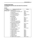
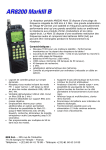
![Stealth Protect Series catalogue 2011_We[...]](http://vs1.manualzilla.com/store/data/005809212_1-caf297493bfcf938dba2b64bb0d79842-150x150.png)