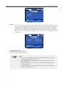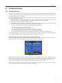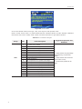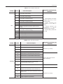
1
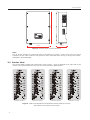
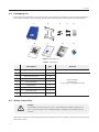
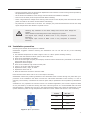
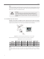
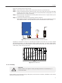
TM
SAMIL POWER
Expert for PV Grid-tied Inverters
SolarLake PV Grid-tied Inverter
Product Manual
SP–SL–V5.1–EN
English
Copyright Declaration
The copyright of this manual belongs to Samil Power Co., Ltd. Any corporation or individual should not plagiarize,
partially copy or fully copy it (including software, etc.), and no reproduction or distribution of it in any form or
by any means. All rights reserved.
Samil Power reserves the right of final interpretation. This manual is subject to change according to user’s or
customer’s feedback. Please check our website at www.samilpower.com for latest version.
01
02
Contents
1
2
3
4
Basic Safety Information
7
1.1
Preface
7
1.2
General Information
7
1.3
Safety Instruction
7
1.4
Assembly
8
1.5
Transport
8
1.6
Electric Connection
8
1.7
Operation
9
1.8
Maintenance And Repair
1.9
EMC / Noise Level Of Inverter
Product Description
10
2.1
Function
10
2.2
Electrical Block Diagram
10
2.3
Dimension
11
2.4
Product Label
12
Protect Device
13
3.1
Power Off
13
3.2
Strengthen The Protection Device
13
Installation
13
4.1
Installation Process
13
4.2
Packaging List
14
4.3
Safety Instruction
14
4.4
Installation Precaution
15
4.5
Preparation
16
4.6
Installation Steps
16
4.7
Connections Of The PV Power System
17
4.8
5
6
9
10
4.7.1
Announcements
17
4.7.2
PV Array Connection Types
17
4.7.3
Assembly Steps Of DC Connector
18
4.7.4
Assembly Steps Of AC Connector
20
4.7.5
Grounding
21
Safety Inspection
22
Run The Inverter
22
5.1
Inspect The Cable
22
5.2
Start Inverter
23
5.3
Check Country Setting And PV Array Connection Type
23
5.3.1
Check Grid-tied Country Setting
23
5.3.2
Check The PV Array Connection Type
25
Operation
26
6.1
Control And Display Panel(Figure 24)
26
6.2
LCD Settings
27
6.3
6.2.1
Standard Interface
27
6.2.2
Main Menu
28
6.2.3
Instantaneous Data
28
6.2.4
Historical Data
28
6.2.5
Event List
28
6.2.6
Settings
28
LCD Function
34
03
7
8
9
10
11
04
Communication And Monitoring
35
7.1
Communication Interface
35
7.2
Communication Mode
35
7.2.1
RS232 Communication For Standalone Type
35
7.2.2
RS485 Communication For Several Inverters
35
7.2.3
Ethernet Communication
37
Troubleshooting
41
8.1
Troubleshooting
41
8.2
Daily Maintenance
46
Decommissioning
46
9.1
Decommissioning Steps
46
9.2
Package
46
9.3
Storage
46
9.4
Disposal
46
Technical Data
47
10.1
Input (DC)
47
10.2
Output (AC)
47
10.3
Efficiency, Safety And Protection
48
10.4
General Data
48
Manufacture Warranty And Liability Clauses
49
● Notes on This Manual
This manual is an integral part of the inverter. Please read the product manual carefully before installation,
operation or maintenance. Keep this product manual for future reference. Please note that all pictures are
edited by Samil Power.
● Scope of Validity
This product manual describes the assembly, installation, commissioning, and maintenance of the following
Samil Power SolarLake Series inverters.
SolarLake 10000TL
SolarLake 12000TL
SolarLake 15000TL
SolarLake 17000TL
Keep this manual where it will be accessible at all times.
● Target Group
This manual is for qualified person (support person, service person are qualified mentioned in this manual).
The tasks described in this manual must only be performed by qualified person.
● Symbols Used
This manual provides safety operation information and uses the symbol in order to ensure personal and
property security and use the inverter efficiently when operating the inverter. You must understand and
absolute these emphasize information to avoid the personal injury and property loss. Please read the
following symbols which used in this manual carefully.
Danger
Danger indicates a hazardous situation which. if not avoided, will result in
death or serious injury.
Warning
Warning indicates a hazardous situation which, if not avoided, could result in
death or serious injury.
Caution
Caution indicates a hazardous situation, if not avoided, could result in minor or
moderate injury.
Note
Note provides tips that are valuable for the optimal operation of user product.
Attention
Attention indicates there are potential risks, if fail to prevent may lead to
equipment cannot run normally or property damage.
05
● Symbols on the Inverter
There are some symbols which are related to issue of security. Please first read and fully understand
the content of the symbols, and then install equipment.
Symbol
Explaination
30 min
There is residual voltage in the inverter! Ensure that AC/DC side are
not charged before installation and maintenance. But when inverter
DC side disconnect for a period of time, capacitance still charge, so
wait for 30 minutes to ensure the capacitance discharge.
Be careful of high voltage.
Be careful of high temperature.
Symbol of CE:
Inverter is accord with CE safety certification standard.
If cause some kinds of property destruction and personal injury without according to the instructions of
this manual. Samil Power Co., Ltd does not take any responsibility for that.
06
Basic safety information
1
Basic safety information
Note
If you have any questions or problems when you read the following information,
please contact Samil Power Co., Ltd.
1.1
Preface
Installation of SolarLake invertermust be completely accord with national and local power grid standards and
regulations.
● Please contact recently authorized repair center if you need any maintenance or repairs. If you want to
know the information of authorized center, please contact your dealer. Please don't maintenance by
yourself or it could cause property destruction and personal injury.
● Read and understand the instruction of this manual ,and be familiar with relevant safety symbols in the
paragraph, then start to install and debug the equipment.
● According to the national and state requirements, before connect the grid, you must get power department
permission, and perform the operation only by qualified electrical engineer.
● Before installing and maintaining the equipment, you should cut off the high voltage application of PV array.
You can also open the switch of SolarArray Combiner to cut off the high voltage. Otherwise, serious injury
may be caused.
1.2
General information
Some parts are electrically charged and some parts are scalding when the inverter is working. Some kinds
of property destruction and personal injury will be caused if unauthorized improper use or wrong install,
wrong operate. The inverter must be transported, loaded, installed and maintained by qualified electrical
engineer(must abide by the effective accident prevention rules of users’ country!)
According to the basic safety rules, qualified electrical engineer should have the ability of assembling,
starting and operating the product and have necessary conditions and qualifications of performing.
Samil Power Co., Ltd does not take any responsibility for the property destruction and personal injury
because of any incorrect use.
1.3
Safety instruction
Danger
Danger to life due to high voltages in the inverter!
• All work on the inverter must be carried out by qualified person only;
• The appliance used by children or persons with reduced physical sensory or
mental capabilities, or lack of experience and knowledge, unless they have
been given supervision or instruction;
• Children should be supervised to ensure that they do not play with the
appliance.
Caution
Danger of burn injuries due to hot enclosure parts!
• During working only can touch the display and key parts of inverter.
07
Basic safety information
Attention
PV array should be connected to the ground in accordance with
requirements of local power department
To protect system and the personnel security, we suggest that PV array of
border and inverter should be reliable grounding.
Warning
Ensure input DC voltage ≤ Max.DC voltage .Over voltage may cause
permanent damage to inverter or other losses, which will not be included in
warranty!
Advertencia
Disconnect both AC and DC power from the inverter before opening the
machine shell and maintaining only by professional electrical engineer.
1.4
Assembly
Please install and start SolarLake inverter according to the following sections. Put the inverter in
appropriate bearing capacity objects (such as wall and components and so on), to ensure that inverter
vertical placed. Choose suitable place for installing electrical equipment. And assure enough fire exit
space, convenience for maintenance. Maintain proper ventilation, and ensure that have the enough air
cooling cycle.
1.5
Transport
In our factory test center, we has strictly tested and inspected on SolarLake inverter to ensure the high
quality of our products. The product has been in a best electrical, mechanical state. Our product is special
packed to ensure that inverter is not damage because of transportation. However, transports accident
could still happen. The transportation company is responsible for damage.
When take delivery of the goods, please check inverter. If you find packing problems that may cause the
damage of the inverter, or find any visible damage, please immediately notice the responsible
transportation company. You can ask solar equipment installation contractor or Samil Power Co., Ltd for
help if necessary.
Must use original package or appropriate package when transportation inverter, to ensure the equipment
transported safely.
1.6
Electric connection
Please comply with all the current electrical regulations about accident prevented in dealing with the
current inverter.
Danger
Before the electrical connection, make sure to use opaque material to cover
the PV battery or disconnected PV panels DC switch. Exposure to the sun, PV
array will produce a dangerous voltage.
08
Basic safety information
Warning
All installation accomplished only by professional electrical engineer.
• Must be trained;
• Completely read the manual operation and understand relevant matters.
Attention
Only get permission by the local power department and complete all electrical
connection by professional electrical engineer then connect inverter into grid.
1.7
Operation
Attention
Some internal components will be fever when inverter is working. Please wear
protective gloves.
Danger
Touching the power grid or the terminal of equipment may lead to die of electric
shock or fire.
• Don’t touch the terminal or conductor which connect to the power
• circuit.
Pay attention to anything about grid connection and security document.
1.8
Maintenance and repair
Danger
• Disconnected with the PV components array and electricity grid before any repair
work.
After turn off AC breaker and DC switch for 5 minutes later, the maintenance or repair
of the inverter can be carried out.
Attention
Inverter should work again after removing any faults. If you need any repair
work, please contact with the local authorized service center.
Attention
Can’t dismounting the internal components of inverter without authorized. Samil
Power Co., Ltd does not take any responsibility for the losses from that.
09
Basic safety information & Product description
1.9
EMC / noise level of inverter
Electromagnetic compatibility (EMC) refers to that one electrical equipment functions in a given
electromagnetic environment without any trouble or error, and impose no unacceptable effect upon the
environment. Therefore, EMC represents the quality characters of electrical equipment
●
●
●
The inherent noise-immune character: immunity to internal electrical noise Panel Invert
External noise immunity: immunity to electromagnetic noise in external system
Noise emission level: influence of electromagnetic emission upon environment.
Warning
Electromagnetic radiation from inverter may be harmful to health.
• Please do not continue to stay away from the inverter in less than 20 cm when inverter
is working.
2
Product description
2.1
Function
The SolarLake Series is a PV inverter which converts the DC current of a PV generator into AC current
and feeds it into the public grid.
PV Modules
Grid-tied Inverter
Grid
Figure 1 PV Grid-tied System
Manufacturing SolarLake inverter uses the latest technology, and strictly observe well recognized safety
procedures. Even so, misoperation will cause property destruction and personal injury.
Inverter must be reliably connected to utility power grid when working. The inverter is not designed for
mobile application.
The inverter was not used in any other or additional purposes. The manufacturer/supplier does not take
any responsibility for that. For purpose, must strictly abide by these relevant specifications of the manual.
2.2
Electrical block diagram
● Electrical block diagram
SolarLake inverter internal function module diagram is presented in figure 2. The DC power which
generate from PV components array is filtered through Input Board .Before enter into inverter DC voltage
is increased by Boost Board. Functions of Input Board are insulation impedance detection, auxiliary power
and input DC voltage / current detection. Internal MPP tracker of inverter insure inverter producing max
power. DC power is changed into AC power by Inverter Board full-bridge circuit. Control Board provides
the control mode and monitors running state of inverter by LCD Board. LCD Board displays fault
information in normal running conditions. ControlBoard also can trigger Output Board internal relay so as
10
Product description
to protect the internal components, Except that, ControlBoard has the functions of residual current
detection, output DC voltage / current detection and EMC function.
Communication Interface
LCD
Input
Boost
Inverter
Output
Board
Board
Board
Board
Output to grid
Solar input
Control Board
Figure 2 Electrical block diagram(DC switch optional)
●
Terminals of PV inverter
Ethernet
Ethernet
RS-485
RS-485
RS-232
RS-485
RS-232
ON
1
2
OFF
AC GRID
AC Output
DC Switch
DC Input
Figure 3 Terminals of PV inverter for 10 KW~17 KW(DC switch is optional)
Note:
For safety reasons, the use of a DC switch is recommended between the PV modules and the power
modules. Customers can select Samil Power SolarLake series inverters according to application
requirements. DC switch is built in SolarLake inverter.
2.3
Dimension
●
Dimension for SolarLake 10000TL, SolarLake 12000TL, SolarLake 15000TL and
SolarLake 17000TL
11
716mm
Product description
520mm
230mm
Figure 4 Overview of the inverters dimension
Note:
The AC output terminal is most length part at the bottom of inverter, so take care of the AC output
terminals. Do not make it stand on the ground or other materials while moving or lifting the inverters,
otherwise it will be damaged.
2.4
Product label
The product label provides basic information of the inverter, which is attached to the right side of the
inverter. Pay special attention to the type of inverter and other specifications.
SolarLake 10000TL
SolarLake 12000TL
SolarLake 15000TL
SolarLake 17000TL
Figure 5 Labels for SolarLake10000TL,SolarLake12000TL,SolarLake 15000TL
and SolarLake 17000TL(From left to right)
12
Protect device & Installation
3
Protect device
3.1
Power off
Inverters will be disconnected physically in safe condition when the local power goes off or the equipment
is maintained to protect the person working on the power grid. It is correspond with current national
standards and regulations. SolarLake inverter is equipped with automatic disconnected protection system
to avoid any possible island operation.
Attention
If want to know more details or possible reasons for malfunction of equipment,
please refer to part 8 of manual.
3.2
Strengthen the protection device
SolarLake inverter equipped with additional protection device to ensure that operate safely in any case
safety .These protection include:
√ Continue to monitor the voltage of grid to keep voltage and frequency in a limit range (according to
relevant countries and regions grid standard);
√ Limit the power automaticallybased on the internal temperatureso as not to overheating
√ Automatically measurement:
●
●
●
●
●
Measure
Measure
Measure
Measure
Measure
DC voltage of PV array;
the three-phase frequency of gird;
the temperature of equipment
input/output current of equipment
output power of equipment.
4
Installation
4.1
Installation process
● Ready to install(refer to 4.2、4.3、4.4、4.5)
Complete the preparation before installation:
......√ � Read the user manual carefully;
......√ �Check the products and parts;
......√ �Inspection installation tools;
......√ �Checkthe installation environment.
● Mechanical installation(refer to 4.6)
Work during mechanical installation:
......√ �Fix the panel of inverter;
......√ �Install inverter.
● Electrical connection(refer to 4.7)
Work during electrical connection:
......√ �Connect DC side;
......√ �Connect AC side;
......√ �Ground joint;
......√ �Connect line of communication.
● Safety inspection(refer to 4.8)
Work during safety inspection:
......√ �Inspect PV array;
......√ �Inspect AC side;
......√ �Inspect DC side;
......√ �Inspect the line of grounding, communication and accessory connection.
13
Installation
4.2
Packaging list
Please check the package list, find out all these in the package. The product on the list are forinstallation.
If find some damage or some missing, please contact Samil Power’s sales.Figure6 is the packing list
1
2
6
3
7
4
8
5
9
TM
Sami
Exper
t for
l Powe
PV Grid-t
ied Invert
r
ers
Sola
rRiv
Prod er PV Grid-tied
Inve
uct
-EN
Man rter
ual
SP-S
R-V5
Figure 6 Packaging list
Table 1 Packing list
4.3
Description
QTY
1
SolarLake inverter
1
2
Back panel
1
3
Input DC connector
4
4
RJ45
3
5
Screw package
1
6
Packing list
1
7
Product manual
1
8
Warranty card
1
9
Quality certificate
1
Remark
Screw package:
2 M4 screws,
5 ø6 screws, 5 expansion screws
Safety instruction
Danger
DC voltage can be as much as 1000 V, three-phase AC voltage reaches up to
400 V. Ensure AC/DC side uncharged before installing and maintaining the
inverter.
Must strictly observe the following standard and specifications when installing, operating and maintaining
SolarLake inverter.
14
Installation
①
Get the permission from the local power department then combine inverter to the grid and operate by
the professional electrical engineer.
②
All the electrical installation must comply with local electrical installation standard.
③
Don't touch the other parts except terminals When installing.
④
There is high electrical voltage when working. Must cut off inverter AC/DC power and external control
power and wait for at least 5 minutes before maintaining
⑤
Pay attention to surface heat of inverter. For example, the power Semiconductor Devices still keep
higher temperature after blackout a period of time.
Warning:Pay attention to the rated voltage and current when design the
system.
Please assess the following factors when designing PV system:
The largest input voltage of MPPT circuit in any case(refer to technical
features);
The largest input current of MPPT circuit in any case(refer to technical
features).
4.4
Installation precaution
Checking environment where system is installed:
SamilPower suggests customer checking the installation site. Do not fall into any of the following
conditions:
●
●
●
●
●
●
●
●
●
●
The ambient temperature is outthe range of -20°C to +60°C (Power derating at 45°C).
Higher than the altitude of about 2,000 m above sea level.
Prone to be damaged by sea water.
Close to corrosive gas or liquid (for example, locations where chemicals are processed or the location
where feed lots of poultry).
Exposed to direct sunlight.
Prone to be flooded or high levels of snow pack.
Little or no air flow and high humidity.
Exposed to steam, vapor, or water.
Exposed to direct cool air.
Near the television antenna or antenna cable.
Fault because of the above case is not in the scope of warranty.
SamilPower assures the product guarantee of the SolarLake series inverters during five years after your
purchase. If the installation site does not meet the instructions described in this manual, it is out of
warranty. The warranty is limited to the costs of repair and/or replacement of the product by SamilPower
only.
Ventilation is very important to cool the inverter. For outdoors application, the inverter requires at least
50 cm (see table 2) of clearance among the other units and ground. It is recommended that the same
clearance(50cm). Installing the inverter in the place mentioned above may cause the malfunction of the
system caused by water or high temperature inside the inverter. Please note that it is out of warranty.
50cm
50cm
50cm
Standard
50cm
11-04-03 10:12:17
Today
5 hours
Total
14.6 kwh
1 minutes
52.7 kwh
5 hours
Normal
15.21 kw
Esc
OK
14.60 kw
49.99 Hz
<ESC> to Main Menu
50cm
Figure 7 Space specification
Position
Min. Size
Side
50cm
Top
50cm
Bottom
50cm
Front
50cm
Table 2 Available Space Size
15
Installation
4.5
Preparation
Below tools are needed before installation.
Figure 8 Installation Tools
Installation Tools: crimping pliers for binding post and RJ45, screw drivers and manual wrench and ф 8
driller, rubber hammer.
4.6
Installation Steps
Step1: Drill holes in the wall with ф 8 driller according to the size of bracket. Keep drilling vertical to the
wall, and don’t shake when drilling to avoid damage to the wall. It need repositioning and drilling
holes if the hole with much error. Then put expansion pipe into the hole vertically, use rubber
hammer to tap the pipe into the wall completely. After that, 5 screws should be twisted into pipes
with bracket. See step 1.
Step 1
Step 2
Step 3
Step 4
Figure 9 Bracket Installation
Step2: Use the bracket to install the inverter onto the narrow vertical panel (or wall). Make upper corner part
of inverter hanging onto the bracket. Lower part match the standard of the bracket. See step 2.
Step3: Make sure the bracket and the inverter side screw holes in a line and matching well. Put the
screw(there are left and right 2 screws ) into the hole and drive into the inverter tightly. See step 3.
16
Installation
Step4: Lock the inverter and the bracket with lock for safety consideration. (This is optional for users. User
can select the lock according to your requirements). See step 4.
4.7
Connections of the PV power system
4.7.1 Announcements
Warning
Ensure that the DC side is not charged before installation and maintenance.
But after DC side discharge for a period of time, the capacitor is still charged,
so need to wait for 5 minutes to ensure that the capacitors is discharged.
Attention
Only professional electrical engineer can install the inverter.
● PV String input connection
Danger
Before the electrical connection, make sure to use opaque material to cover
the PV battery or disconnected PV panels DC side of. Exposure to the sun, PV
array will produce a dangerous voltage.
Note
There are 2 independent MPP trackers in inverter.PV arrays connected to one
MPP tracker should be a unified structure, including the same specification, the
same number and the same angle.
4.7.2
PV array connection types
PV array connection types: There are 2 independent MPP trackers in inverter. We can choose
common-string input connection and multi-strings input connection. We recommend that choose
multi-strings connections to harvest max. PV power.
Input1
Input2
Input1
Input2
DC
DC
DC
DC
AC
AC
Output
AC
AC
Output
Figure 10 Multi-string input connection (Left) and common-string input connection (Right)
17
Installation
Note:
Make sure the right setting (PV string connection setting) via LCD commissioning steps according to
your PV string input connection. Please refer to part5.3 and part 6.2 for details.
Please select PV modules with excellent function and reliable quality. Open-circuit voltage of module
arrays connected in series should be <Max. input DC input voltage. Operating voltage should be
conformed to MPPT voltage range.
Table 3 DC Voltage Limitation
SolarLake
10000TL
SolarLake
12000TL
SolarLake
15000TL
SolarLake
17000TL
320~800 Vdc
380~800 Vdc
380~800 Vdc
430~800 Vdc
Model
MPPTvoltage range
Max.DC voltage
1000 Vdc
Please use PV cable to connect modules to inverter. From junction box(Must have fuse spec.:1000V,
25A fast action) to inverter, voltage drop is about 1-2%. So we suggest the inverter install near PV
module, in order to save cable and reduce DC loss.
Note
Please don’t connect the PV panel positive or negative to ground. And do not
apply for thin film panel.
4.7.3 Assembly steps of DC connector
4.7.3.1 Steps of create DC connector
Step 1:Loosing the screw as following figure.
Step 2: Stripped of the DC insulating layer about 8mm, and then connect the bare wire core into
............core tube of connectors.
18
Installation
Step 3: Insert the cable with the tube core into the fastening nut.
Step 4: Insertthe core tube into slot of connection until hear the voice indicating in place.
Step 5: Tight nuts according to the opposite direction. Now wiring is finished.
4.7.3.2 Electrical connections of DC side
Steps of connections:
Step 1: Equip the breaker or SolarArray Combiner with lighting protection in DC side.
Step 2: Disconnect the breaker or disconnect SolarArray Combiner with SolarLake inverter.
Step 3: Open-circuit voltage of module arrays connected in series<1000V.
Step 4: Connect the positive and negative connector into the terminals on the bottom of inverter.
Step 5: Connect the other input in the same way.
Figure 11 Usemultimeter to measure module array voltage
19
Installation
Note:
There are 4 terminals in the bottom of inverter. Left two are DC input terminals of PV1. Right two
are DC input terminals of PV2. Grounding of PV1 and PV2 can not be connected together or it will
report the fault information. Check the PV+ and PV- from the PV string combiner box correctly.
Make sure PV+ and PV- are connected correctly.
Warning
PV module voltage is very high which belongs to dangerous voltage
range. Please comply with electric safety rules when connecting.
When there is something wrong with module arrays, modules can be
connected with PV grid-tied inverter only after eliminating these
problems.
4.7.4 Assembly steps of AC connector
SolarLake series inverters are designed for three phases grid. Phase voltage is 230±20%,
according to requirements of different countries. Typical frequency is 50Hz. Other technical
requests should comply with the requirement of local public grid. Below figure 12-14 is the AC
output area (terminal block) and 5 wires of cable installation method introduction.
Figure 12 AC output area with terminal block for 5 wires of cable
Below is the AC cable specification table when select the cable for installation.
Table 4 Cable and Micro-breaker Requirement
Model
Cable (Cu)
Micro-Breaker
SolarLake
10000TL
SolarLake
12000TL
SolarLake
15000TL
SolarLake
17000TL
≥4mm²
≥4mm²
≥6mm²
≥6mm²
25A
25A
32A
32A
Note:
For safety reasons, make sure you select the correct specification cables for installation.
Otherwise the power will make the cable hot and overload. It could result in death or serious
injury.
20
Installation
Below are the steps for AC output wiring.
Step 1: Get out of the four screws at four corners of the AC cover, get off the cover.
Step 2: There are 5 white terminals, which are PE, N, L3(T), L2(S), L1(R). Put the 5 wire of AC cable
through the house tunnel, then put the wire into the terminals correctly(make sure the
phase sequence is correctly connected).
Step 3: After 5 wires are connected with terminals please check the wire is in right location.(L wire
is connected with L terminal)
Step 4: Put the terminal house on the terminals, get four screws on.
RCMU breaker should be installed between inverter and grid, and its rated fault current:
100 mA≤Ifn≤300 Ma, 0.1S. Any load should not be connected with inverter directly.
Esc
OK
Input
Output
Figure 13 Incorrect Connections between Load and Inverter
Impedance of SolarLake inverter AC connecting dot should be less than 2Ω. To ensure reliable
anti-islanding function , PV cable should be used to ensure wire loss <1% than normal power.
Moreover, length between AC side and grid connecting dot should be less than 150m. Below chart is
cable length, section area and wire loss.
Figure 14 AC Cable Loss
4.7.5 Grounding
Attention
Neither positive nor negative could grounding because of no transformer, or
it will break down.
In the system, all non-current-carrying metal parts (such as shell of combiner, distribution and inverter)
should be connected to the earth.
21
Installation & Run the inverter
PV String
AC Switchboard
Inverter
L1
L2
L3
N
PE
Earth
Link
PV module frame
Figure 15 Grounding of syste
● Connection of communication
Please refer to part 7.2.2
4.8
Safety inspection
PV array
Inspect the PV array to determine whether each PV array opening voltage meets the standardbefore operating
the inverter.
− Record all the measurement accurately;
− Ensure positive and negative polarity correct.
Collection of inverter DC side
Confirm DC side no voltages and currents by multimeter.
Check the wiring of DC side. Look out for the wiring of polarity, and be consistent with PV array. Measure each
DC input voltage (open). Ensure that polarity is correct. Check voltage bias (in stable weather). If the bias is
more than 3%, may be the problem of PV array.
Collection of inverter AC side
Ensure that the breaker of inverter AC side is “OFF”. Check whether the inverter is connected to the grid
correctly and check whether the voltage of each phase is at a predetermined range. Measure THD (total
harmonic distortion) possibly, then check the curve. If it is distorted seriously, the inverter may not run.
5
5.1
Run the inverter
Inspect the cable
Attention
Inspect all operations, especially inspect whether DC voltage and AC voltage is
in accordance with the range permitted by the inverter.
● Check grid collection of AC side
Check whether the breaker of user’s AC side is disconnected;
SolarLake inverter AC side is three-phase which supplying 400V to grid. Check whether inverter is
connected to grid correctly ( TN-C, TN-S or TT ) and check the collection of PE, N, L3(T), L2(S), L1(R) is ok.
● Check collection of DC input
Check whether the switch of DC side is “OFF”.
AC current source connected to inverter by the main DC cable, Voltage of each main cable should almost
be same and can’t exceed the maximum DC voltage of inverter. In addition to voltage inspection, also
have to check each main cable polarity. Error of polarity of main cable may damage to the SolarLake
inverter. Please check all DC collection again and make sure they are connected firmly.
22
Run the inverter
5.2
Start inverter
Step 1: Turn on DC switch.
Step 2: If it’s the first starting the inverter, please check country setting and PV array connection type
accords to part 5.3.(The default setting of PV array connection type: Multi-string input
connection)
Step 3: Turn on AC breaker;
When the solar arrays generate enough power, inverter will startupautomatically.LCD show “normal” state
which indicates that inverter startup success. If the LCD standard interface shows“permanent”, press
key”ESC” to main menu, press down arrow key to “Event list”, then press “OK”, if there is “inv 44” fault, it
indicates that phase sequence of AC grid is wrong. You should take following measures:
1.
2.
3.
4.
Turn off AC breaker and DC switch.
Wait for 5 minutes.
Exchange the L1 and L2 lines in AC terminals.
Turn on AC breakers and DC switch.
If the invertershows other fault, please refer to part 8--error table.
Note
If the inverter fail, please refer to part 8 --error table.
5.3
Check country setting and PV array connection type
Safety has been set corresponding of provisions of the country in the factory and PV array connection type is
set to multi-string. Checking whether these two settings are correct by following steps.
5.3.1
Check grid-tied country setting
Enter standard interface automatically after startup (If not the standard interface, press “ESC” return to the
standard interface), as shown in figure 16.
Standard
11-04-03 10:12:17
Today
5 hours
Total
14.6 kwh
1 minutes
52.7 kwh
5 hours
Normal
15.21 kw
14.60 kw
49.99 Hz
<ESC> to Main Menu
Figure 16 Standard interface
In the standard interface press “ESC” button then enter the main menu, as shown in figure 17.
23
Run the inverter
Main Menu
11-04-03 10:14:12
Instantaneous
History
Event List
Settings
System Info
<ESC> to Main Menu
Figure 17 Main menu
Press the down arrow key to move the cursor to the" Settings" and then press “OK” key to enter setup
interface, as shown in figure 18.
Settings
11-04-03 10:16:10
Language
Calibration
Time
Update
Country
LCD
AutoTest Ita.
Clear Prod.
Network
Clear Events
Input
Factory Set.
<ESC> to Main Menu
Figure 18 Setup interface
Press the down arrow key to move the cursor to the" Country", then press “OK” key to enter the local
country setting interface, as shown in figure 19.
Commissioning Country
Germany
GreeceContin.
Italy
GreeceIslands
Australia
Netherland
Spain
Belgium
Czech
Bulgaria
Germany
VDE0126-1-1
Current:Germany
Figure 19 Local country setting interface
Check whether the settings of local country is correct. If it is correct, press ”ESC” to enter standard
interface.
If it is not correct, press the up, down, left or right arrow key to move the cursor to select country, then
press “OK” key. Now a password is needed, press the up key and down key to modify the password, and
press the right key and left key to move the cursor. Enter the password and then press “OK” key to confirm
the selection. Then it will return to the standard interface automatically.
Note
When setting grid-tied country and PV array connection type or recovering
Factory Set, please enter the password 000111.
24
Run the inverter
5.3.2 Check the PV array connection type
Enter setup interface by the same way as how to check the local country setting.
Standard
11-04-03 10:12:17
Today
5 hours
Total
14.6 kwh
1 minutes
52.7 kwh
5 hours
Normal
14.60 kw
15.21 kw
49.99 Hz
<ESC> to Main Menu
Figure 20 Standard interface
In the standard interface press ESC button then enter the main menu, as shown in figure 21.
Main Menu
11-04-03 10:14:12
Instantaneous
History
Event List
Settings
System Info
<ESC> to Main Menu
Figure 21 Main menu
Press the down arrow key to move the cursor to the" Settings" and then press “OK” key to enter setup
interface, as shown in figure 22.
Settings
11-04-03 10:16:10
Language
Calibration
Time
Update
Country
LCD
AutoTest Ita.
Clear Prod.
Network
Clear Events
Input
Factory Set.
<ESC> to Main Menu
Figure 22 Setup interface
Press the down arrow key to move the cursor to the" Input", then press “OK” key to enter input setting, as
shown in figure 23.
25
Run the inverter & Operation
Commissioning Input
Common-String
Multi-String
Current : Common-String
Figure 23 Type of PV array connection
Check whether the current PV array connection type is correct. Please refer to section 4.7.2" PV array
connection types " to distinguish type of PV array connection.
If it is correct, press”ESC” to return to the standard interface.
If it is not correct, press the up, down arrow key to move the cursor to select right type, then press “OK”
key. Now asked to enter a password, press the up key and down key to modify the password, press the right
key and left key to move the cursor . Enter the password and confirm the selection. Then it will return to the
standard interface automatically.
6
6.1
Operation
Control and Display Panel(figure 24)
Red LED
Green LED
Buttons
LCD
Figure 24 Display and control panel
There are 6 buttons:OK, ESC, UP, DOWN, RIGHT, LEFT.
OK button: confirm the selection.
ESC button: exit current screen or selection
UP button: move cursor to up selection or increase the values
DOWN button: move cursor to down or decrease the values.
RIGHT button: move cursor to right side or increase the backlight.
LEFT button: move cursor to left side or decrease the backlight.
26
Operation
Standard
11-04-03 10:12:17
Today
5 hours
Total
14.6 kwh
1 minutes
52.7 kwh
5 hours
Normal
14.60 kw
15.21 kw
49.99 Hz
<ESC> to Main Menu
Figure 25 HMI Interface
There are two LEDS on the panel. Different LED status means inverter different working statutes.
Table 5 LED statutes
LED
GREEN LED
RED LED
OFF
FLASH
ON
Fault or Permanent state
or appear unrecoverable
serious fault
Wait or Check state, not
appear unrecoverable
serious fault
Normal state, not appear
unrecoverable serious
fault
No fault
Appear recoverable fault
Appear unrecoverable
serious fault
Wait State: Inverter is waiting to CheckState until the end of reconnection time. In this state, the PV
voltage is more than 250V and grid voltage value is between the max and min limit; Otherwise, Inverter
will go to FaultState or PermanentState.
Check State: Inverter will check isolation resistor, relays, and other safety requirements. It will also do
self-test to ensure inverter software and hardwareare functional. Inverter will go to FaultState or
PermanentState if any error or fault occurs.
Normal State: Inverter feeds to grid energy from PV panel as much as possible according MPP trackers.
Inverter will go to FaultState or PermernentState if any error or fault occurs.
Fault State: Inverter has occurred some recoverable error. It can recover if the errors disappear. If
FaultState exist continually, you should check the inverter according error code in table 6,7,8,9,10.
Permanent State: Inverter has occurred some unrecoverable error. It will stay in PermenentState. You
should take some measure according the error code.
6.2
LCD settings
6.2.1 Standard interface
Enter the standard interface after starting up, as shown in figure 26.
Standard
11-04-03 10:12:17
Today
5 hours
Total
14.6 kwh
1 minutes
52.7 kwh
5 hours
Normal
15.21 kw
14.60 kw
49.99 Hz
<ESC> to Main Menu
Figure 26 Standard interface
27
Operation
6.2.2 Main menu
In the standard interface press “ESC” button then enter the main menu. Main menu is as shown in figure
27.
Main Menu
11-04-03 10:14:12
Instantaneous
History
Event List
Settings
System Info
<ESC> to Main Menu
Figure 27 Main menu
6.2.3
Instantaneous data
Move the cursor to the" Instantaneous" and then press “OK”, the user will see the input, output voltage,
current, power, temperature, insulation and other real-time information.
6.2.4
Historical data
Move the cursor to the" History" and then press “OK”, the user will see the power amount histogram of
every hour. The user press the left or right arrow key to see the DC input power curve, the AC output
power curve, daily electricenergy production histogram in the current month, mensal electricenergy
production histogram in the current in the current year and the the annual power generation column in
recent 20 years.
6.2.5
Event list
Move the cursor to the" Event List" and then press “OK”, the user will see the list of events of inverter.
Record 100 event information at most. Press the up or down keys to select events, and press “OK” to
get the details of the event, including the occurrence time, error code. Press the ESC button to return
to the superior interface progressively.
6.2.6
Settings
Move the cursor to the" Settings" and then press “OK”, the user will enter the setting interface, as shown
in figure 28. Press up, down, left or right to select options, and then press “OK” to enter the option.
Settings
11-04-03 10:16:10
Language
Calibration
Time
Update
Country
LCD
AutoTest Ita.
Clear Prod.
Network
Clear Events
Input
Factory Set.
<ESC> to Main Menu
Figure 28 Setting interface
Note:
If the user wants to reset the Country ( grid located ), input ( PV array connection type ) or Factory Set
( restore factory settings ), need to input password to enter the option. Please enter the password
000111.
28
Operation
6.2.6.1
Setting of grid-tied country
Steps of grid-tied country settings refer to “5.3.1 Check grid-tied country setting”.
6.2.6.2
Type of PV array connection
Steps of type of PV array connection settings refer to “5.3.2 Check the PV array connection
type”.
6.2.6.3
Restore factory settings and enable settings
If the user select Factory Set ( restore factory settings ) in figure 28. System will ask whether
to do this setting. If you want to give up, press “ESC”. If you press “OK”, inverter will clear the
power record, record events, settings of grid-tied country and type of PV array connection after
the user input password. Press right or left arrow key to select the position of figure and press
up or down arrow key to adjust figure when inputting password. Inverter will prompt the (OK )
to start commissioning. Now the user press “OK” and then set the inverter parameters. The
display will display enable interface, as shown in figure 29.
Samil Power Co.,Ltd.
SolarLake17000TL
T170000001
Control CPU
Redundant CPU
Communication CPU
1 . 22
1 . 22
1 . 22
< OK > to start Commissioning
Figure 29 Enable interface
Step 1: Language setting
Press “OK” key to enable settings, and will enter Language setting interface. Press up or down
arrow keys to select the corresponding language, and then press “OK” to confirm the
selection. Then, press “OK” to enter the next step, as shown in figure 30.
Commissioning Language
English
Deutsch
Français
Español
Italiano
Figure 30 Language setting
Note:
Language settings is unrelated with Grid-tied country settings.
Setp2:Grid-tied country setting
Next interface is grid-tied country setting interface, as shown in figure 31. Different countries
have different grid safety rules. Press the up arrow key, down, left or right arrow key to
select corresponding country, and then press “OK” to confirm the selection. Then, press “OK”
key to enter the next step.
29
Operation
Commissioning Country
Germany
GreeceContin.
Italy
GreeceIslands
Australia
Netherland
Spain
Belgium
Czech
Bulgaria
Germany
VDEO126-1-1
Current:Germany
Figure 31 Grid-tied country setting
Step3:Setting of PV array connection type
Next interface is PV array connection type interface, as shown in figure 32. The user should
select input connection type correctly according to the actual situation. Press up or down
arrow keys to select, and then press “OK” to confirm. Then, press “OK” key to enter the next
step.
Commissioning Input
Common-String
Multi-String
Current : Common-String
Figure 32 Setting of PV array connection type
Step 4:Date and time settings
Date and time settings interface as shown in figure 33, set according to the local date and
time. Press left or right arrow key to move the cursor, press the up or down arrow keys to
change value, then press “OK” to confirm the selection.Display time in the upper right corner
of LCD. Then, press “OK” key to enter the next step.
Note:
Inverter will check whether the setting is legitimate when changing the time automatically, and
prevent illegal time value. If find be unable to modify time, please check whether it is legitimate.
Commissioning Time
YYYY
MM
DD
2011 - 04 - 03
hh
mm
ss
10 : 04 : 47
Figure 33 Date and time settings
30
Operation
Step 5:Check boot settings information
LCD will display the settings information. Please check the settings information. If settings is
wrong, please press the “ESC” key to reset. If all the information is correct, please press “OK”
to confirm, the inverter will save all the settings. As shown in figure 34.
Commissioning End
11-04-03 10:04:51
Germany
Common-String
<OK> to start running
<ESC> to back
Figure 34 Check boot settings information
6.2.6.4
Autotest procedure- Italy only
Only country setting is Italy during commissioning, Enter main menu then enter setting
sub-menu, select AutoTestIta. to run, an automatic test of the inverter will initialed by software,
user can get the information via the LCD.(Main menu→Settings→AutoTestIta.) See figure 35.
Settings
11-04-03 10:16:10
Language
Calibration
Time
Update
Country
LCD
AutoTest Ita.
Clear Prod.
Network
Clear Events
Input
Factory Set.
<ESC> to Main Menu
Figure 35 Autotest selection for Italy only
Make sure during commissioning the country is Italy, then inverter can do self-test automatically
follow above instructions.
Operate a new AutoTest procedure
1. Before performing the AutoTest, confirm the country setting is “Italy” and the inverter is
running in normal state.
2. On the display Main Menu find (Settings→ AutoTestIta.) and press OK, then select “New
Autotest” , press OK , the LCD will be cleared, wait a few seconds, and you can see “(OK) to start
Grid R V_max” on the LCD.
3. Press OK button to start grid R V_max test, or press ESC button to exit from “New Autotest”.
If there is no button operation within 5 seconds, the test will start automatically. If the test has
started, key operation is invalid until test is over.
4. After grid R V_max test is over, the LCD will show the result and “(OK) to start V_min”, and
the inverter will reconnect automatically.
5. Then press OK button to start grid R V_min test. Alternatively press ESC button to exit from
“New Autotest”. If there is no button operation within 5 seconds, the test will start automatically.
If the test has started, key operation is invalid until test is over.
6. After grid R V_min test is over, the LCD will show the result and “(OK) to start F_max” , and
the inverter will reconnect automatically.
31
Operation
7. Then, press OK button to start grid R F_max test. Alternatively press ESC button to exit from
“New Autotest”. If there is no button operation within 5 seconds, the test will start automatically.
If the test has started, key operation is invalid untill this test is over.
8. After grid R F_max test is over, the LCD will show the result and “(OK) to start F_min” , and
the inverter will reconnect automatically.
9. Then, press OK button to start grid R F_min test. Alternatively press ESC button to exit from
“New Autotest”. If there is no button operation within 5 seconds, the test will start automatically.
If the test has started, key operation is invalid untill this test is over.
10. After grid R F_min test is over, the LCD will show the result and “(OK) to start Grid S
V_max” , and the inverter will reconnect automatically.
11. Then, press OK button to start grid S V_max test. Alternatively press ESC button to exit from
“New Autotest”. If there is no button operation within 5 seconds, the test will start automatically.
If the test has started, key operation is invalid untill this test is over.
12. After grid S V_max test is over, the LCD will show the result and “(OK) to start V_min”, and
the inverter will reconnect automatically.
13. Then, press OK button to start grid S V_min test. Alternatively press ESC button to exit from
“New Autotest”. If there is no button operation within 5 seconds, the test will start automatically.
If the test has started, key operation is invalid untill this test is over.
14. After grid S V_min test is over, the LCD will show the result and “(OK) to start F_max”, and
the inverter will reconnect automatically.
15. Then, press OK button to start grid S F_max test. Alternatively press ESC button to exit from
“New Autotest”. If there is no button operation within 5 seconds, the test will start automatically.
If the test has started, key operation is invalid untill this test is over.
16. After grid S F_max test is over, the LCD will show the result and “(OK) to start F_min”, and
the inverter will reconnect automatically.
17. Then, press OK button to start grid S F_min test. Alternatively press ESC button to exit from
“New Autotest”. If there is no button operation within 5 seconds, the test will start automatically.
If the test has started, key operation is invalid untill this test is over.
18. After grid S F_min test is over, the LCD will show the result and “(OK) to start Grid T
V_max”, and the inverter will reconnect automatically.
19. Then, press OK button to start grid T V_max test. Alternatively press ESC button to exit from
“New Autotest”. If there is no button operation within 5 seconds, the test will start automatically.
If the test has started, key operation is invalid untill this test is over.
20. After grid T V_max test is over, the LCD will show the result and “(OK) to start V_min”, and
the inverter will reconnect automatically.
21. Then, press OK button to start grid T V_min test. Alternatively press ESC button to exit from
“New Autotest”. If there is no button operation within 5 seconds, the test will start automatically.
If the test has started, key operation is invalid untill this test is over.
22. After grid T V_min test is over, the LCD will show the result and “(OK) to start F_max”, and
the inverter will reconnect automatically.
23. Then, press OK button to start grid T F_max test. Alternatively press ESC button to exit from
“New Autotest”. If there is no button operation within 5 seconds, the test will start automatically.
If the test has started, key operation is invalid untill this test is over.
24. After grid T F_max test is over, the LCD will show the result and “(OK) to start F_min”, and
the inverter will reconnect automatically.
25. Then, press OK button to start grid T F_min test. Alternatively press ESC button to exit from
“New Autotest”. If there is no button operation within 5 seconds, the test will start automatically.
If the test has started, key operation is invalid untill this test is over.
26. After grid T F_min test is over, the LCD will show the result and “(Esc) to exit”, and the
inverter will reconnect automatically.
27. Theautotest function is considered successful once all the previous 12 tests have been
performed. When LCD shows “(Esc) to exit”, press ESC button to exit from “New Autotest” .
32
Operation
Note:
If an unexpected disconnection requirement occurs during the autotest, the autotest is
interrupted. The LCD will show "AutoTest break! (OK) to exit". Press OK button or ESC button to
exit from “New Autotest” . Then, disconnect the AC breaker from all 3 phases and prevent it
from being reactivated, disconnect the DC switch for 5 minutes and connect it again. The
inverter is now in the initialization and you can restart the autotest procedure.
Note:
If user exit from “New Autotest” when any of the previous 12 tests be not performed yet, the
inverter will not record any of the test results.
Procedure of viewing AutoTest results from the inverter’s LCD
Enter Main Menu, then enter Settings sub-menu, select “AutoTest.” and enter it, then select
“Last Results” , press OK button, the LCD will show the latest several results’ time in terms of a
list. The lattest result shows on the top.
Press DOWN or UP button to select one result and press OK button to view the detail. When
entering the detail screen, test results of grid R are shown, press RIGHT or LEFT button to view
other phases’ results. Press ESC button to exit from detail screen.
Procedure of viewing AutoTest results from PC
Note:
After a new AutoTest finished, the results’ data will be sent to PC through the RS-232 port
between the inverter and PC, one “txt” format report will be created automatically. The detailed
operation procedures are as follows:
28. Open the “Enel.exe” file shown in figure 36 in PC(User can download “Enel.exe” application
software from www.samilpower.com ), one "Report" folder will produced at the same directory
with “Enel.exe“ file , and each time “txt” format report generated will be stored to the "Report"
folder, as shown in Figure 37.
Figure 36
Figure 37
29. elect the corresponding models and communication port( PC and the inverter connection
port: com1 ~ com9), as shown in figure 38 and figure 39.
Figure 38
Figure 39
33
Operation
30. Then click "OK" button, “Enel.exe” software automatically reads the inverter’s LATEST test
data, and generates a “txt” format report, as shown in figure 40 and figure 41.
Figure 40
Figure 41
31. If you click “OK” button, one warning message as shown in figure 42 appears, please check
the RS-232 communication connection between the Inverter and PC.
Figure 42
In figure 27, press up, down, left or right arrow key to move the cursor to the" System Info" and
then press “OK”, you will see the machine serial number, software version number and so on.
Press “ESC” and will return to the superior interface progressively.
6.3
LCD Function
LCD shows the most of power information user cares. When the inverter operates normally, user touch
any button, then the backlight is on, user will see the standard interface.
If none key touching in 60 seconds, the backlight will be off. After that user touch any button, the
backlight will be on.
Note that if no operation in 60 seconds, the backlight will goes off. In next 10 seconds if still no operation
the screen will back to standard menu, otherwise the backlight will be illuminated.
Note:
After starting inverter and restoring the factory settings, LCD background light will not shut down
automatically.
34
Communication and Monitoring
7
7.1
Communication and Monitoring
Communication Interface
This product has a communication interface of RS485(standard),Ethernet/RS232(optional)
Operating information like output voltage, current, frequency, fault information, etc., can be delivered to
PC or hardware storage devices or other monitoring equipment via communication interface.
7.2
Communication mode
When user want to know the information of the power station and manage the entire power system. We
offer below 3 types communications.
7.2.1
RS232 Communication for standalone type
RS232 is one communication interface. It transmits the data between PC and one single SolarLake
series inverters (figure 43). For communication cable, one end is male connector; the other end is
female connector.
Figure 43 RS232 Communication Diagram
One inverter can only be communicated with one PC at the same time through RS232 port. Thus this
method is generally used for single inverter’s communication, for examples,software updating and
serviceman’s testing.
7.2.2
RS485 Communication for Several inverters
RS485 is generally for multiple inverters’ communication. Up to 32 inverters could communicate at the
same time, but wire length should be≤1200m. SolarPower Manager can be used for monitoring multiple
inverters at the same time. Users can browser the PV plants operating data collected by SolarPower
Manager through PC. Connecting the system as blow (figure44), user can easily monitoring the PV
power station.
35
Communication and Monitoring
Figure 44 SolarPower Manager Monitoring Diagram
Two types of cable must be prepared when using SolarPower Manager for monitoring multipleinverters.
The communication cable between inverter and inverter:
1. Prepare two 8-PIN RJ45 connectors, to hold the RJ45 connector with the 'clip' on the bottom. To
have to the 'opening' (where you insert the cable) facing you, the order number is 1 to 8 from left
to right.
2. Use a length of communication cable, then push the 8 color wires into the modular plug follow the
same order as shown below.
1
Green
2
Green white
3
Blue
4
Orange white
5
Orange
6
Blue white
7
Brown white
8
Brown
3. Then put the both ends of communication cable into the communication ports of inverter
respectively. If there are N inverters, need N-1 this communication cable.
The communication cable between inverter and SolarPower Manager:
1. Prepare one 8-PIN RJ45 connector and one 4-PIN RJ11 connector. To hold the RJ45 connector with
the 'clip' on the bottom. To have to the 'opening' (where you insert the cable) facing you. The order
number is 1 to 8 from left to right of 8-PIN RJ45 connector, the order number is 1 to 4 from left to
right of 4-PIN RJ11 connector.
2. Use a length of communication cable, then push the wires into the connector follow the same order
as shown below.
36
1
Green
2
Green white
3
Blue
4
Orange white
5
Orange
1
Blue white
6
Blue white
2
Blue
7
Brown white
3
Green white
8
Brown
4
Green
Communication and Monitoring
3. Put the 4-PIN RJ11 connector into the SAMIL COM of SolarPower Manager, put the 8-PIN RJ45
connector into the first or the last one of inverters.
Please see Installation Guide of SolarPower Manager for more information.
Note:
If you want to use SolarPower Manager to monitor numerous SolarLake inverters, every inverter must
have two RJ45 modular jack for RS485. Under the default configuration, COM1 port on inverter is for
ethernet, COM2、COM3 port on inverter is for RS485.
7.2.3
Ethernet communication
User can connect inverter with the router (the router is not special for inverters, user can get any brand in
the market.) according to the requirements, then user can check the inverter’s data in any place of the
world.
WAN
Router
Figure 45 Ethernet communication
Hardware Requirements: Support only windows operating system, includingxp,vista,win7.
Network interface for inverter: COM1.
Monitor mode: LAN and WAN.
LAN: Install SolarPower Browser(Not less than v2.3) in the PC which can monitor inverters .In this mode,
you can use a router or nonuse.
If you use a router, you can monitor 254 inverters.
Parameter setting for router:
Step 1: Enter standard interface automatically after startup (If not the standard interface, press
“ESC” return to the standard interface), as shown in figure 46.
Standard
11-04-03 10:12:17
Today
5 hours
Total
14.6 kwh
1 minutes
52.7 kwh
5 hours
Normal
15.21 kw
14.60 kw
49.99 Hz
<ESC> to Main Menu
Figure 46 Standard interface
37
Communication and Monitoring
Step 2:
Press “ESC” in standard interface then enter the main menu, as shown in figure 47.
Main Menu
11-04-03 10:14:12
Instantaneous
History
Event List
Settings
System Info
<ESC> to Main Menu
Figure 47 Main menu
Step 3:
Move the cursor to the" settings" and then press “OK”, will enter settings interface, as shown
in figure 48.
Settings
11-04-03 14:20:31
Language
Calibration
Time
Update
Country
LCD
AutoTest Ita.
Clear Prod.
Communication
Clear Events
Input
Factory Set.
<ESC> to Main Menu
Figure 48 Settings interface
Step 4:
Move the cursor to the" Communication" and then press “OK”, will enter IP settings interface,
as shown in figure 49.
Communication
11-04-03 14:19:06
Auto IP
Static IP
IP Address
Subnet Mask
Gateway
DNS Server
<ESC> to confirm
Figure 49 IP settings interface
Step 5:
Move the cursor to the" Auto IP" and then press “OK”. Inverter will prompt user to conform
Auto IP and press “OK”. Now setting is over. Rebooting LCD then enter standard interface
automatically.
If you don’t use a router, you can only monitor 1 inverter. Need to use cable to connect inverter with
PC.
38
Communication and Monitoring
Parameter setting for nonuse router:
Step 1: Enter standard interface automatically after startup (If not the standard interface, press "ESC"
with proper times return to the standard interface return to the standard interface), as shown
in figure 50.
Standard
11-04-03 10:12:17
Today
5 hours
Total
14.6 kwh
1 minutes
52.7 kwh
5 hours
Normal
14.60 kw
15.21 kw
49.99 Hz
<ESC> to Main Menu
Figure 50 Standard interface
Step 2: Press “ESC” in standard interface then enter the main menu, as shown in figure 51.
Main Menu
11-04-03 10:14:12
Instantaneous
History
Event List
Settings
System Info
<ESC> to Main Menu
Figure 51 Main menu
Step 3:
Move the cursor to the" settings" and then press “OK”, will enter settings interface, as shown
in figure 52.
Settings
11-04-03 14:20:31
Language
Calibration
Time
Update
Country
LCD
AutoTest Ita.
Clear Prod.
Communication
Clear Events
Input
Factory Set.
<ESC> to Main Menu
Figure 52 Settings interface
Step 4: Move the cursor to the" Communication" and then press “OK”, will enter IP settings interface,
as shown in figure 53.
39
Communication and Monitoring
Communication
11-04-03 14:19:06
Auto IP
Static IP
IP Address
Subnet Mask
Gateway
DNS Server
<ESC> to confirm
Figure 53 IP settings interface
Step 5:
Move the cursor to the" Static IP" and then press “OK”, as shown in figure 54. Now the cursor
stop at the first figure. Press right or left arrow key to move the cursor to select the figure
which need to be modified. Press up or down arrow key to modify figure(IP Address:
192.168.000.002、Subnet Mask:255.255.255.000, the others are 0, as shown in figure 54).
Press “OK” after modifying. LCD will display the setting parameter and press “OK” again,
setting is over. LCD interface will Reboot and
then enter into standard interface
automatically.
Communication
11-04-03 14:19:29
Auto IP
Static IP
IP Address
192.168.000.002
Subnet Mask
255.255.255.000
Gateway
000.000.000.000
DNS Server
000.000.000.000
<ESC> to confirm
Figure 54 IP settings interface
Parameter set for PC:
Set IP address as 192.168.000.001,
Set Subnet mask as 255.255.255.000.
Note
① Need to install SolarLake Inverter Monitoring software in the PC when
using RS232, Ethernet communication.
② Can’t using RS232, RS485 and Ethernet communication mode for a PC
at the same time.
③ The default set is “Auto IP”. If router is used, LAN or WAN monitor is ok
without any setting.
④ In WAN mode, router is necessary and auto IP mode should be selected.
⑤ WAN is not applicable by now.
40
Troubleshooting
8
Troubleshooting
8.1
Troubleshooting
This section contains information and procedures for solving possible problems with the SolarLake series
inverters, and provides user with troubleshooting tips to identify and solve most problems that could occur
with the SolarLake series inverters.
This section will help user narrow down the source of any problems user may encounter. Please read the
following troubleshooting steps.
1. Check thewarning or fault messages on the System Control Panel or Fault codes on the inverter
......information panel. If a message is displayed, record it before doing anything further.
2. Attempt the solution indicated in table 6 ,7,8,9,10.
3. If inverter information panel is not displaying a Fault light, check the following list to make sure that
......the present state of the installation allows proper operation of the unit.
— Is the inverter located in a clean, dry, adequately ventilated place
— Have the DC input breakers been opened
— Are the cables adequately sized and short enough
— Are the input and output connections and wiring in good condition
— Are the configurations settings correct for user particular installation
—Are the display panel and the communications cable properly connected and undamaged
Contact Samil Power Customer Service for further assistance. Please be prepared to describe details of
user system installation and provide the model and serial number of the unit.
View the warning on screen and the steps of false information:
Press “ESC” then enter the main menu in the normal interface. In the interface press “downward” and
select “Event List”, then press “OK” to enter events list shown as figure 55.
Event List
11-06-24 09:11:11
47 Inverter
06-24 09:05:29 ON
46 Inverter
06-24 09:05:29 ON
45 Inverter
06-24 09:05:29 ON
44 Inverter
06-24 09:05:29 ON
7 Grid
06-24 09:05:29 ON
16 Grid
06-24 09:05:29 ON
14 Grid
06-24 09:05:29 ON
12 Grid
06-24 09:05:29 ON
41 Inverter
06-24 09:05:29 ON
40 Inverter
06-24 09:05:29 ON
<ESC> to Main Menu
1/5
Figure 55 Events list
When SolarLake Inverter is at fault, the fault information is composed of “group+code” displayed on LCD.
There 3 kinds of faults( Grid、PV and Inverter). One code indicates one fault. For example "Grid 3"
indicates under voltage L2 phase. Another type of fault is for user, recording modify settings by user.
In the events list display the type of event, code, occurring time and current status.
Press the right or to the left key can flip and press upward or downward key move the cursor. Press “OK”
key can view the details of selected event, shown as figure 56.
41
Troubleshooting
Event Details
Start time
Inverter
11-06-24 09:11:20
2011-06-24 09:05:29
47
Turn off both AC and DC power to the inverter, o n c e the inverter has lost power turn the AC and DC back on.
If the inverter resumes fault operation
, please call support.
<ESC> to Event List
Figure 56 Event Details
In the event details shows event type, code, occurring time and operation hints.
Please contact Samil Power Co.,Ltdforfurthertechnical assistance.Please provide detailed installation
information and inverter model, serial number and fault information to get optimal solution.
Table 6 Error code list of AC grid
Group
Grid
42
Code
Fault description
0
L1 phase over-voltage
1
L1 phase under-voltage
2
L2 phase over-voltage
3
L2 phase under-voltage
4
L3 phase over-voltage
5
L3 phase under-voltage
6
Over-frequency
7
Under-frequency
8
DC component of L1 phase is too large
9
DC component of L2 phase is too large
10
DC component of L3 phase is too large
11
L1 phase over- frequency
12
L1 phase under- frequency
13
L2phase over- frequency
14
L2phase under- frequency
15
L3 phase over- frequency
16
L3 phase under- frequency
Suggestion operation and
Solutions
① Check whether AC grid(voltage
and frequency) is beyond the
scope;
② Check whether the connection
of AC side is correct;
③ If still at fault, please ask for
help.
Troubleshooting
Table 7 Error code list of DC side
Group
PV
Code
Fault description
0
DC side PV1 over-voltage
(input mode: Multi-String)
1
DC side PV2 over-voltage
(input mode: Multi-String)
2
DC side under-voltage
(input mode: Common-String)
3
DC side over-voltage
(input mode: Common-String)
4
PV1 insulation impedance error
5
PV2 insulation impedance reeor
6
Insulation impedance protects power source
auxiliary
7
Input current is not balanced.
(input mode: Common-String)
8
Leakage current error
9
30 mA jumping error
10
60 mA jumping error
11
150 mA jumping error
12
Leakage current more than 300 mA
Suggestion operation and
Solutions
① Check whether the output
voltage of PV array is in the
allowing range.
② Check whether the
insulation of PV cable is
good;
③ Inspect whether the
installation is correct
according to the manual.
④ If still at fault, please ask
for help.
Table 8 Error code list of inverter
Group
Code
Fault description
0
Start working
1
Electrify communication board
2
Electrify control board
3
Blackout of control board
4
Read clock of communication board error
5
Write clock of communication board error
6
Read communication board EEPROM error
7
Write communication board EEPROM error
8
Communicate between control board
communication board error
Inverter
Suggestion operation and
Solutions
Without any remedy
Ask for help if still at fault
after rebooting.
9~29
30
CPU Communication between main control
board and subordinate control board error
31
Main control board and subordinate control
board error
32
Auxiliary power source error
33
High temperature protection
Without any remedy
43
Troubleshooting
Continued:
Wechsel
richter
44
34
Phase locking error
35
Bus under-voltage
36
Bus over-voltage
37
Bus voltage unbalanced
38
Bus Hardware over-voltage protection
(restore)
39
Output hardware over-current protection
(restore)
40
Boost hardware over-current protection
41
Over-current of output(RMS)
42
Choose input mode error
Check whether the collection of PV
array is the same with setting
43
Self- checking error
Ask for help if still at fault after
rebooting.
44
Phase of output error
Check electricity wiring after
power off. Ask for help if still at
fault
45
AD port using to gathering output voltage error
46
AD port using to gathering output current error
47
AD port using to gathering DCI error
48
AD port using to gathering GFCI error
49
IAC_RMS_Unbalance
50
The output hardware over-current protection
(not resume)
51
Bus hardware over-voltage protection
(not resume)
52
Boost1 over-current protection
53
Boost2 over-current protection
54
Output over-current (instantaneous date)
(not resume)
55
Relay can't be disconnect
56
Relay can't be closed
57
Unrecoveriac_rms_unbalance
Without any remedy
Ask for help if still at fault after
rebooting.
Without any remedy
Ask for help if still at fault after
rebooting.
Troubleshooting
Continued:
58
Fan 1 error
59
Fan 2 error
60
Fan 3 error
61
Check the fan. If not turn,
contact to exchange.
Control board EEPROM read and write error
Ask for help if still at fault
after rebooting.
Table 9 User operation accord
Group
Code
User
Description
0
Start serial upgrade program
1
Modify the language
2
Modify the time
3
Modify the country
4
Modify the input method
5
Clean up the production records
6
Clean up event record
7
Restore factory settings
8
Modify the LCD brightness
9
Modified the LCD time
10
Suggestion operation and
Solutions
Without any remedy
Modified the network Settings
Table 10 Other error
Group
Other error
Code
0
Description
LCD displays waiting at all times
Suggestion operation and
Solutions
Ask for help if still at fault after
rebooting.
Note:
“Without any remedy” means that the event is not error, or inverter will resume from error automatically.
45
Troubleshooting & Decommissioning
8.2
Daily maintenance
Inverters generally do not need any maintenance or correction, but need to ensure cooling fan not be
covered by any dust or dirties.
● Inverter cleaning
Please use electric compressing dryer, soft dry cloth or brush to clean inverters. Water, corrosive chemical
substance or intense cleaning agent is not allowed to clean the cooling fan.
● Cooling fin cleaning
To ensure inverter performance and long-period usage, back heat emitter needs to be left with available
space, side fan cannot be covered with dust or snow as it will affect airflow. Please use compressing air,
soft cloth or brush to clean cooling fin, not water, corrosive chemical substance or intense cleaning agent.
9
Decommissioning
9.1
Decommissioning steps
●
●
●
●
●
Switch off the AC grid
Switch Off the DC switch
Wait for 5 minutes
Release the DC connectors
Release the AC terminals via screw drivers.
Now inverters can be demounted in a safe way.
9.2
Package
If possible, please pack the inverter with the original packaging. If it is no longer available, user can also
use an equivalent carton that meets the following requirements: Suitable for loads more than 50 kg;
With handle; Can be fully closed.
9.3
Storage
Store the inverter in dry place where ambient temperatures are always between -25 °C - +70 °C.
9.4 Disposal
Please be sure to deliver inverters at the end of its service and packing materials to certain site (it should
apply disposal regulations for electronic scrap), where can assist relevant department to dispose and
recycle.
46
Technical Data
10 Technical Data
10.1
Input (DC)
SolarLake
10000TL
SolarLake
12000TL
SolarLake
15000TL
SolarLake
17000TL
Max. recommended DC power
[W]
10400
12500
15600
17700
Max.DC voltage [V]
1000
1000
1000
1000
A:16/B:16
A:16/B:16
A:20/B:20
A:20/B:20
2/2
2/2
2/2
2/2
320~800
380~800
380~800
430~800
160/210
160/210
160/210
160/210
SolarLake
10000TL
SolarLake
12000TL
SolarLake
15000TL
SolarLake
17000TL
Model
Total max. input Current [A]
Number of MPP trackers /
strings per MPP tracker
MPPT voltage range
(at full power) [V]
Min. DC voltage /
start voltage [V]
10.2
Output (AC)
Model
AC nominal power [W]
10000
12000
15000
17000
Max. AC power [W]
10000
12000
15000
17000
Max. AC current [A]
16
19.2
24
25
3/N/PE,
230/400
3/N/PE,
230/400
3/N/PE,
230/400
3/N/PE,
230/400
AC grid freq. [Hz]
50
50
50
50
Power factor(cos)
0.9leading…….
0.9lagging
0.9leading…….
0.9lagging
0.9leading…….
0.9lagging
0.9leading…….
0.9lagging
<3%
<3%
<3%
<3%
Nominal AC voltage [V]
Total harmonic distortion
(THD)
47
Technical Data
10.3
Efficiency, Safety and Protection
SolarLake
10000TL
SolarLake
12000TL
SolarLake
15000TL
SolarLake
17000TL
Max. efficiency
97.9%
97.9%
98.0%
98.0%
Euro- efficiency
97.4%
97.4%
97.6%
97.6%
MPPT efficiency
99.9%
99.9%
99.9%
99.9%
Overvoltage / Undervoltage
protection
Yes
Yes
Yes
Yes
DC isolation impedance
monitoring
Yes
Yes
Yes
Yes
Yes
Yes
Yes
Yes
Grid monitoring
Yes
Yes
Yes
Yes
Ground fault current
monitoring
Yes
Yes
Yes
Yes
DC injection monitoring
Yes
Yes
Yes
Yes
SolarLake
10000TL
SolarLake
12000TL
SolarLake
15000TL
SolarLake
17000TL
520*716*230
520*716*230
520*716*230
520*716*230
50
50
50
50
<47
<47
Model
Ground fault protection
10.4
General Data
Model
Dimension (W/H/D) [mm]
Weight [kg]
Cooling concept
Noise emission (typical) [dB]
Fan
<47
Operating temperature
range [°C]
<47
-20 °C ~ +60 (Derating at 45 °C)
Degree of protection
IP65
Pollution Degree
II
Topology
Internal consumption (night)
[W]
LCD display
48
Transformerless
<5
<5
<5
<5
3.5Inch,
TFT-LCD
3.5Inch,
TFT-LCD
3.5Inch,
TFT-LCD
3.5Inch,
TFT-LCD
Technical Data & Manufacture warranty and liability clauses
Continued:
Communication interfaces
Ethernet/ RS232/
RS485
Ethernet/ RS232/
RS485
Standard warranty(Year)
5
5
Ethernet/ RS232/ Ethernet/ RS232/
RS485
RS485
5
5
11 Manufacture warranty and liability clauses
Samil Power Co., Ltd offers 5 years warranty service for SolarLake inverter. Warranty period is from the
date of installation. But the longest period don’t exceed 66 months from the date of delivering goods.
During the warranty period, Samil Power Co., Ltd guarantees normal function of the SolarLake inverter. If
there are faults within our responsibility, we will provide maintenance free of charge. During the warranty
period, if inverter appears malfunction or fault, please contact your dealer or installation contractor.
The followings are not included in the scope of warranty:
● �Use SolarLake inverter for other purpose;
● �Install incorrectly or not conform to the rule;
● �Improper operation
● �Useunqualified protection when working;
● �Modify the equipment without authority;
● �Damage because of external factors or the majeure force(such as lightning, over-voltage, bad
.......... weather, and fire, earthquake, tsunami and so on);
● �Poor ventilation;
● �Don’t comply with the relevant safety regulations;
● �Transportation damage.
49
50
SAMIL POWER CO., LTD.
Marketing & Sales Office
Factory
Add:
Add:
No.52,Huigu Innovation Park, Huishan District,
Wuxi,Jiangsu Province,P.R.China 214174
Tel:
+86 510 83593131
Fax: +86 510 81819678
E-mail:[email protected]
http://www.samilpower.com
Tel:
Fax:
No.66 Taihangshan Road,
Suyu Economic Development Zone, Suqian City,
Jiangsu Province, P.R.China 223800
+86 527 88754666
+86 527 84453877