1
Bosch DCN Standalone Automatic Camera Control
DCN-SWSACC
en
Software Manual
Bosch DCN Standalone Automatic Camera
Control
Table of Contents | en
3
Table of Contents
1
Introduction
5
1.1
System license key
5
2
Installation
6
2.1
Allegiant video switcher
6
2.1.1
Configuration
6
2.1.2
Operation
7
2.2
AutoDome
7
2.2.1
Configuration
7
2.2.2
Operation
8
2.3
Cables
8
2.4
Software Installation
9
3
The DCN-SWSACC application
10
3.1
The application main screen
10
3.1.1
Menu (1)
11
3.1.2
Workflow buttons (2)
11
3.1.3
Configuration list (3)
11
3.1.4
Content panel (4)
11
4
System
12
4.1
PC Communication Settings
12
4.2
Video Url
12
5
Cameras
13
5.1
Camera System Type
13
5.2
Camera Control Settings
13
5.3
Add/Remove camera
14
5.4
Camera Information
14
6
Assign & store
15
6.1
Temporarily PC with 2 serial ports
16
6.1.1
Start configure
16
6.1.2
Assigning the overview
16
6.1.3
Assigning cameras and prepositions to a unit
17
6.1.4
Remove disconnected units
17
6.1.5
Camera menu
17
6.2
Temporarily PC with 1 serial port
18
Bosch Security Systems B.V.
Software Manual
DCN-SWSACC_V4.0 | V1.0 | 2011.10
4
Bosch DCN Standalone Automatic Camera
Control
en | Table of Contents
7
Upload
19
8
Print layout
20
9
Warning and error reports
21
Index
26
DCN-SWSACC_V4.0 | V1.0 | 2011.10
Software Manual
Bosch Security Systems B.V.
Bosch DCN Standalone Automatic Camera
Control
1
Introduction | en
5
Introduction
Version 4.0, 2011-10-24.
DCN-SWSACC Standalone Automatic Camera Control of the DCN Conference systems
interfaces with the Bosch Allegiant or AutoDomes. It selects fixed or prepositioned cameras to
be activated to display the current active speaker at a conference.
Automatic Camera Control in conference applications
When a chairman’s or delegate’s microphone is activated on the equipment, the camera
assigned to that position is activated. When no microphones are active, an ‘overview’ is
automatically selected. The image can be displayed on hall displays or other screens together
with information about the current speaker, such as delegate identification (seat text). The
system operator has a screen, which also displays information about which camera is active.
Automatic Camera Control provides an extra dimension to conference proceedings.
Configuration
The DCN-SWSACC software runs on a PC which is temporarily connected to configure the
DCN Next Generation or DCN Wireless Discussion System and the Bosch Allegiant or
AutoDomes. With this PC the camera positions can be defined using the on-screen Pan, Tilt
and Zoom control and stored as prepositions in the AutoDome camera. At the same time a
delegate position is linked to a camera preposition. When all delegate positions are linked to
camera prepositions the configuration needs to be uploaded to the DCN Conference system
where it will be stored persistent in the CCU or NCO. The configuration file can be printed and
stored on the temporarily PC for later use. After configuration the PC is removed and Bosch
Allegiant or AutoDome is directly connected to the DCN Conference system.
Copyright
No part of this documentation may be reproduced or transmitted in any form by any means,
electronic, mechanical, photocopying, recording, or otherwise, without the prior written
permission of the publisher.For information on getting permission for reprints and excerpts,
contact Bosch Security Systems B.V.
1.1
System license key
The use of the DCN Standalone Automatic Camera Control is depending on the DCN system
license key. Depending on the license key, which is located in the system’s Control Unit,
functions are enabled or disabled.
The license key can be uploaded to the system with the Download and License Tool.
NOTICE!
For demo purposes a demo license is available. In case you have a demo license the Bosch
logo in the right top of the application will note "Demo version not for sale". The demo version
is fully operational but will not be supported. Contact your local Bosch representative if you
have a demo license while you purchased an official license.
Bosch Security Systems B.V.
Software Manual
DCN-SWSACC_V4.0 | V1.0 | 2011.10
6
Bosch DCN Standalone Automatic Camera
Control
en | Installation
2
Installation
This chapter describes how to setup the DCN system and the Camera system. Two different
types of DCN systems are available: single CCU systems and multi CCU systems. Also the
Camera system exists in two different versions: Allegiant video switcher with multiple
cameras and AutoDome which is a single camera.
The system needs to be configured before it can be used operational. To do so, first the
choice has to be made which Camera system is used:
–
Section 2.1 Allegiant video switcher, or
–
Section 2.2 AutoDome.
–
Section 2.3 Cables
–
Section 2.4 Software Installation
2.1
Allegiant video switcher
2.1.1
Configuration
1.
Set the PC Communication Settings:
–
Allegiant: set the baud-rate of the Allegiant to 19k2. Please refer to the Allegiant
user manual how to set the Allegiant’s baud-rate.
–
DCN-CCU2: set the protocol for the serial port via menu 8H to allegiant.
–
DCN-CCU (S500): set the protocol for serial port which is connected to the
temporarily PC to camera control and set the baud-rate to 19k2
–
–
2.
DCN-NCO: set the baud-rate for camera control to 19k2 using menu item 7l.
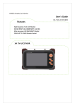
Make the connections to the temporarily PC according the image below:
–
–
3.
Refer to Section 2.3 Cables for cable type (1,6* and 2).
Start the DCN-SWSACC software.
–
Configure the camera control as described in: Section 3 The DCN-SWSACC
application, Section 4 System, Section 5 Cameras and Section 6 Assign & store.
4.
Disconnect the temporarily PC from the DCN system: and the Allegiant.
DCN-SWSACC_V4.0 | V1.0 | 2011.10
Software Manual
Bosch Security Systems B.V.
Bosch DCN Standalone Automatic Camera
Control
2.1.2
Installation | en
7
Operation
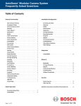
1.
Make the connections according the image below:
–
–
Refer to Section 2.3 Cables for cable type 3.
2.2
AutoDome
2.2.1
Configuration
1.
Set the communication settings:
–
AutoDome: set the baud-rate to 9600. Please refer to the AutoDome user manual
how to set the baud-rate.
–
DCN-CCU2: set the protocol for the serial port via menu 8H to AutoDome.
–
DCN-CCU (S500): set the protocol for serial port which is connected to the
temporarily PC to camera control and set the baud-rate to 9600.
–
–
2.
DCN-NCO: set the baud-rate for camera control to 9600 using menu item 7l.
Make the connections to the temporarily PC according the image below:
–
–
Refer to Section 2.3 Cables for cable types 1,6*, 4 and 6** (**optional: to see a video
image of an AutoDome camera with IP-module in the browser of Assign & store).
3.
Start the DCN-SWSACC software. Refer to Section 2.4 Software Installation.
–
Configure the ‘camera control’ as described in Section 3 The DCN-SWSACC
application, Section 4 System, Section 5 Cameras and Section 6 Assign & store.
4.
Bosch Security Systems B.V.
Disconnect the temporarily PC from the DCN system: and the AutoDome.
Software Manual
DCN-SWSACC_V4.0 | V1.0 | 2011.10
8
Bosch DCN Standalone Automatic Camera
Control
en | Installation
2.2.2
Operation
1.
Make the connections according the image below:
–
–
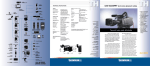
2.3
Refer to Section 2.3 Cables for cable type 5.
Cables
Cable 1. PC to DCN-CCU
Cable 2. PC to Allegiant
Cable 3. CCU/NCO to Allegiant
Cable 4. PC to AutoDome
Cable 5. CCU/NCO to AutoDome
Cable 6. Standard Ethernet cable
DCN-SWSACC_V4.0 | V1.0 | 2011.10
Software Manual
Bosch Security Systems B.V.
Bosch DCN Standalone Automatic Camera
Control
2.4
Installation | en
9
Software Installation
PC requirements
DCN-SWSACC is compatible with Windows Vista and Windows 7 both 32 and 64 bits versions.
Starter editions are not supported.
PC requirements are the same as requested for Windows Vista and Windows 7 by Microsoft.
The DCN system must have version 2.60 or higher.
Installing DCN-SWSACC
DCN-SWSACC needs to be installed from the DVD delivered with the DCN system (check
Bosch Security Systems extranet for the latest version of the software):
1.
Insert the DVD (the software starts automatically).
–
When the software does not start automatically:
–
Select ‘Run...’ from the ‘Start’ menu on the Windows Task bar.
–
Type d:\setup.exe (where d is the DVD drive).
2.
Browse to ‘software’ and select the DCN-SWSACC.
3.
Follow the on-screen instructions.
Bosch Security Systems B.V.
Software Manual
DCN-SWSACC_V4.0 | V1.0 | 2011.10
10
3
Bosch DCN Standalone Automatic Camera
Control
en | The DCN-SWSACC application
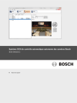
The DCN-SWSACC application
This chapter describes the main part of the application.
3.1
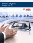
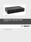
The application main screen
Figure 3.1 Application main screen
1
2
3
4
DCN-SWSACC_V4.0 | V1.0 | 2011.10
Menu
Workflow buttons
Configuration list
Content panel
Software Manual
Bosch Security Systems B.V.
Bosch DCN Standalone Automatic Camera
Control
3.1.1
The DCN-SWSACC application | en
11
Menu (1)
The menu provides access to functionality present in the application.
File
- New (Ctrl+N)
Creates a new configuration.
- Open...(Ctrl+O)
Opens a configuration.
- Save(Ctrl+S)
Saves the configuration to the current configuration filename.
- Save as...
Saves the configuration to a new configuration filename.
- Print (Ctrl+P)
Prints the configuration file.
- Exit (Alt+F4)
Closes DCN-SWSACC.
Tools
- Language settings
Opens a dialog box with the available user interface languages (shown
in native text).
Help
3.1.2
- Contents
Opens the ‘Contents’ of the online help.
- Index
Opens the ‘Index’ of the online help.
- Search
Opens the ‘Search’ of the online help.
- About
Opens the ‘About’ dialog box.
Workflow buttons (2)
The workflow buttons are used to navigate and provide access to the functionality of the DCNSWSACC.
System
PC communication and video URL settings. Refer to Section 4 System.
Cameras
Defines the Camera system and the cameras. Refer to
Section 5 Cameras.
Assign & store
Assign prepositions to the units of the DCN system and store the
prepositions in the Camera system. Refer to Section 6 Assign & store.
Upload
Upload of the configuration to the DCN system. Refer to
Section 7 Upload.
3.1.3
Configuration list (3)
The configuration list is used in: Section 4 System, Section 5 Cameras and Section 6 Assign &
store.
3.1.4
Content panel (4)
The Content panel provides access to: Section 4 System, Section 5 Cameras, Section 6 Assign &
store and Section 7 Upload.
Bosch Security Systems B.V.
Software Manual
DCN-SWSACC_V4.0 | V1.0 | 2011.10
12
4
Bosch DCN Standalone Automatic Camera
Control
en | System
System
This workflow describes the system settings:
4.1
PC Communication Settings
DCN system:
The DCN system: option defines the Serial communication: port of the PC to which the DCNCCU is connected. Selecting --None-- disables the connection to the DCN system:.
For DCN-CCU2 or DCN-NCO a Host name or IP address:must be entered. The IP address of
the unit can be found in the front menu of the DCN-CCU2 or DCN-NCO.
NOTICE!
IP address may not contain leading zeros.
Camera system:
The Camera system: option defines the Serial communication: port of the PC to which the
Camera system: is connected. Selecting --None-- disables the connection to the Camera
system:.
4.2
Video Url
To see a video image of an AutoDome camera with IP-module in the browser of Assign &
store, the following Url: can be used: "http://192.168.0.1/MPEG4.html". Where 192.168.0.1 is
the default IP address of the AutoDome.
NOTICE!
You need to have Sun Java and the MPEG4-ActiveX installed. Refer to the AutoDome user
manual for more information.
In case the Url: is not correct or cannot be reached, the browser reports an appropriate
message or will be empty. Note that the Url: must always start with http://, MPEG must be in
capitals.
The browser in workflow Assign & store is hidden when the Url: is empty or only holds white
spaces.
DCN-SWSACC_V4.0 | V1.0 | 2011.10
Software Manual
Bosch Security Systems B.V.
Bosch DCN Standalone Automatic Camera
Control
5
Cameras | en
13
Cameras
This workflow defines the Camera system and the cameras.
5.1
Camera System Type
The DCN system supports two types of Camera systems:
1.
Allegiant: cameras are connected to the video switcher and multiple screen outputs can
be controlled.
2.
AutoDome: single Pan-Tilt-Zoom camera with single video output.
NOTICE!
When the AutoDome is selected a warning message appears if more than one camera is
defined for the Allegiant.
The Section 5.1 Camera System Type selection is disabled when the Section 6 Assign & store is
active.
5.2
Camera Control Settings
NOTICE!
With the exception of the function Camera override: the following options are all disabled
when Camera System Type is set to AutoDome.
Use Screen line of DCN-SW:
This check box allows you to take the screen line to be shown on the audience screen as
defined in DCN-SW (also DCN-SWDB is needed).
The screen line can be configured by the DCN-SW configuration application via: “Tools >
Person Identification”.
Double seat text:
This check box allows you to specify that an additional line of text can be entered for each
unit number. The text appears on both the operator screen and audience screens. By default,
this option is not enabled (a single seat text line is displayed).
Camera override:
This check box allows you to determine whether a newly switched-on microphone
automatically activates the camera covering its position (check box is selected), or whether
the camera is only activated when the current microphone is switched-off (check box is
deselected).
Camera movement time:
To hide camera movement (as the camera moves from one position to the next), the overview
camera can be activated and displayed during the movement. The movement time can be set
from 0 to 60 seconds in steps of 0.5 seconds.
Bosch Security Systems B.V.
Software Manual
DCN-SWSACC_V4.0 | V1.0 | 2011.10
14
Bosch DCN Standalone Automatic Camera
Control
en | Cameras
Number of audience screens:
This selection allows you to select the Number of audience screens:. The Number of
audience screens: (excluding the operator screen) can be set from 1 till 4. All audience
screens show the same picture.
NOTICE!
It is recommended that the number selected corresponds to the actual number of audience
screens present in the venue. If the number selected is higher than this, there may be some
reduction in system performance.
5.3
Add/Remove camera
NOTICE!
Add/Remove camera is disabled when the Camera System Type is set to AutoDome
Add a new Camera
A new camera is added to the Section 3.1.3 Configuration list (3). Select the new camera
which allows you to enter the Section 5.4 Camera Information. The add camera option is
disabled when no free camera numbers are available.
Remove a selected camera
This option is always disabled when the Section 5.2 Camera Control Settings is visible since no
camera is selected.
5.4
Camera Information
By selection of the Camera System Type in the Section 3.1.3 Configuration list (3) the Camera
Information option becomes visible and allows you to view, select and change the assigned
cameras settings.
Camera name:
This text box allows you to enter 16 characters to define the Camera name:.
Camera number:
This is the number of the camera.
NOTICE!
This camera number must correspond with the internal address of the camera. Refer to the
camera user manual how to change the internal address.
Movable camera
Cameras used in camera control systems can be either fixed or moveable. This check box
allows you to determine if a moveable camera (check box is selected) or none moveable
camera (check box is deselected) is connected.
Number of prepositions:Number of prepositions:
Fixed cameras cannot automatically adjust their positions. Moveable cameras, such as
AutoDome cameras, can automatically adjust their positions (called Preposition:). This text
box allows you to enter or change the number of camera prepositions for each assigned
camera as defined in Section 6.1.3 Assigning cameras and prepositions to a unit. A maximum of
99 camera prepositions are allowed.
DCN-SWSACC_V4.0 | V1.0 | 2011.10
Software Manual
Bosch Security Systems B.V.
Bosch DCN Standalone Automatic Camera
Control
6
Assign & store | en
15
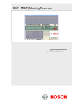
Assign & store
This workflow is used to assign prepositions to the units of the DCN system and store the
prepositions in the Camera system.
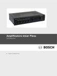
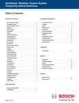
Figure 6.1 Assign & store main window
The Assign & store main window contains the following elements:
1.
Assignment list showing units including the assigned cameras.
2.
Navigation buttons, to navigate through all the units.
3.
Remove selected (disconnected) seat button. To remove a single unit from the list which
is not connected to the DCN system.
4.
Remove all disconnected button. To remove all units from the list which are not
connected to the DCN system.
5.
Start configure button. To start the configuration mode of the DCN system.
6.
Preposition text box to select or define a preposition.
7.
Camera menu button to activate the on-screen Camera menu to change AutoDome
settings which are embedded in the AutoDome (Refer to the AutoDome user manual for
details).
8.
Assign & store button. To assign prepositions to the unit and to store prepositions in the
Camera system.
9.
Pan-Tilt-Zoom-Focus-Iris controls. To control the AutoDome camera.
10. Browser. To see a video image of an AutoDome camera with IP-module.
The system can be configured in two different ways:
1.
Using a Section 6.1 Temporarily PC with 2 serial ports or;
2.
a Section 6.2 Temporarily PC with 1 serial port.
Bosch Security Systems B.V.
Software Manual
DCN-SWSACC_V4.0 | V1.0 | 2011.10
16
Bosch DCN Standalone Automatic Camera
Control
en | Assign & store
6.1
Temporarily PC with 2 serial ports
The following preconditions of Assign & store are required:
1.
Both the DCN system and the Camera system are properly connected and have the
correct settings. Refer to Section 2 Installation for more details.
2.
PC Communication Settings under workflow Section 4 System must correspond with the
3.
The Section 4.2 Video Url must be defined to view the AutoDome video in the browser
4.
Continue with Section 6.1.1 Start configure.
hardware installation.
window.
6.1.1
Start configure
1.
Click the Start configure button.
–
The Start configure button changes into Stop configure button.
CAUTION!
When the connection with the DCN system or Camera system fails the following error
messages could appear:
–
Connection failure. Refer to Section 4.1 PC Communication Settings
–
Incompatible version of the DCN system.
–
Required authorizations missing.
2.
Now all connected units are retrieved from the DCN system. While retrieving a progress
window will be shown. If all units are retrieved they are shown in the Assignment list. By
default the first item in the list is selected, this is the Overview. This Overview will be
shown during the conference if none of the microphones is active or when the Camera
movement time: is not elapsed. The Overview (camera 1) is selected within the
Assignment list.
6.1.2
Assigning the overview
The Overview camera gives a general overview of the conference venue when all the
microphones are off. In case of Allegiant the Overview can also be used when an AutoDome
camera is moving from one preposition to another.
To assign:
1.
Select a Camera:
2.
Select a Preposition if the selected camera is a moveable camera.
3.
Move the camera to the desired position.
4.
Click the Assign & store button. The Camera: and Preposition are assigned to the
Overview and are stored in the Camera system.
After assignment of the Overview the first unit is selected to have a Camera: and Preposition
assigned. The Overview camera can be either a non moveable or moveable (AutoDome)
camera. However, when AutoDome is selected as Camera system, the Overview is always a
preposition of the AutoDome.
DCN-SWSACC_V4.0 | V1.0 | 2011.10
Software Manual
Bosch Security Systems B.V.
Bosch DCN Standalone Automatic Camera
Control
6.1.3
Assign & store | en
17
Assigning cameras and prepositions to a unit
To assign a camera and prepositions to a unit it is first necessary to select that unit. Selecting
a unit number causes all LEDs of the corresponding unit to flash.
There are two ways of selecting the unit:
1.
The DCN-SWSACC software will automatically propose a camera and Preposition. You
can now:
–
Accept this proposal, or change the camera selection and edit fields for Preposition
and Seat text.
2.
Alternatively; press the microphone button or any of the voting keys on a unit.
–
3.
This will result in selection of the Unit in the assignment list.
Click the Assign & store button.
–
The software assigns the camera, Preposition and Seat text to the unit and stores
the prepositions in the Camera system. Automatically the next unit will be selected
and the next Preposition of the selected camera.
NOTICE!
The Allegiant cannot display graphic characters that are used in certain non-European and
non-US languages such as Chinese. Please contact your local Bosch representative how to use
alternative characters.
4.
When all units have a camera assigned the configuration must be uploaded to the DCN
system.
–
Refer to the Section 7 Upload section.
NOTICE!
During configuration, the audience screen continues to show the image from the Overview
camera, except if AutoDome is selected as Camera system then it will show the same view as
the operator screen. The operator screen shows the video of the selected camera.
6.1.4
Remove disconnected units
When a unit is disconnected from the DCN system a disconnect
image is shown in front of
the unit. This unit might be replaced because it was defect. If this unit will not be used
anymore it can be removed by clicking the Remove selected seat button. Click Remove all
disconnected button to remove all disconnected units from the assignment list.
6.1.5
Camera menu
The Camera menu button activates the internal menu of the AutoDome. In this menu special
AutoDome settings can be controlled like inverting the image in case the AutoDome is placed
on a tabletop. Refer to the AutoDome manual for details about the internal menu.
Bosch Security Systems B.V.
Software Manual
DCN-SWSACC_V4.0 | V1.0 | 2011.10
18
6.2
Bosch DCN Standalone Automatic Camera
Control
en | Assign & store
Temporarily PC with 1 serial port
1.
2.
Make a connection between the DCN system and the temporarily PC.
In workflow Section 4 System set the Section 4.1 PC Communication Settings for DCN
system to the correct port.
3.
Start the configuration mode of the DCN system by clicking the Start configure.
–
Now all connected units are retrieved from the DCN system. While retrieving a
progress window might be show. If all units are retrieved they are shown in the
Assignment list.
4.
Click the Stop configure button to stop the DCN system configuration mode.
5.
Disconnect the DCN system from the temporarily PC.
6.
Connect the Camera system to the temporarily PC.
7.
In workflow Section 4 System set the Section 4.1 PC Communication Settings for DCN
system to --None-- and for Camera system to the correct port.
8.
Continue with assigning preposition to the units as described in Section 5 Cameras.
Because the DCN system is not connected the selected unit will not flash the LEDs.
9.
If all cameras and prepositions are assigned, disconnect the Camera system and
reconnect the DCN system.
10. Change the Section 4.1 PC Communication Settings.
11. Start the Section 7 Upload.
DCN-SWSACC_V4.0 | V1.0 | 2011.10
Software Manual
Bosch Security Systems B.V.
Bosch DCN Standalone Automatic Camera
Control
7
Upload | en
19
Upload
This workflow describes Uploading the configuration to the DCN system.
To do so:
1.
Click the Start upload button.
–
The window text is changed into Uploading the configuration to the DCN system.
–
The Start upload button, File (except Exit), Tools menu and Workflow buttons are
disabled.
–
The progress bar is visible and gives the visual indication about the progress of the
upload.
2.
When the Upload process is successfully completed:
–
The window text is changed into Upload successfully finished., the progress bar is
set to 100% and the Start upload button, menu items and Workflow buttons are
enabled.
NOTICE!
The Start upload button is disabled if the Section 4.1 PC Communication Settings for the DCN
System is set to --None-- .
If the Upload process cannot start the window text changes into: Upload failed. and the
progress bar will be hidden.
Failures could be:
–
Unable to set up the connection.
–
Incompatible version of the DCN system.
–
Missing camera control authorization.
If the Upload process failed the window text changes into: Upload failed. and the progress
bar remains on the last value.
Failures could be:
–
Bosch Security Systems B.V.
Lost of connection with the DCN system.
Software Manual
DCN-SWSACC_V4.0 | V1.0 | 2011.10
20
8
Bosch DCN Standalone Automatic Camera
Control
en | Print layout
Print layout
The print function (Section 3.1.1 Menu (1)) allows you to print the camera configuration
settings as given within the table below:
DCN Standalone Automatic Camera Control
Configuration
Name
Camera system
Use Screen line of DCN-SW
Double seat text
Camera override
Movement time
Number of audience screens
configuration1.sacc
ALLEGIANT
No
Yes
Yes
0 seconds
1
Defined Cameras
Camera name
Camera
Camera
Number
1
2
Type
Fixed
Movable
Number of prepositions
1
99
Camera Assignments
ID
0
Seat Type
Overview
Camera
2
Page 1 of 1
DCN-SWSACC_V4.0 | V1.0 | 2011.10
Software Manual
Preposition
1
Seat text 1
Seat text 2
Printed on 4/15/2010 3:58:20 PM
Bosch Security Systems B.V.
Bosch DCN Standalone Automatic Camera
Control
9
Warning and error reports | en
21
Warning and error reports
This section summarizes the warnings and errors and provides the text actually shown.
Warning
Warning when the application exits while configuration process is
active.
Icon
Main instruction
Content
Command links
Button
Warning
Do you want to save the configuration before application exit?
The configuration process is still active.
Save and exit
Exit without saving
Cancel
Warning when the application exits that the configuration is changed
but not yet saved.
Icon
Main instruction
Command links
Button
Warning
Do you want to save the configuration before application exit?
Save and exit
Exit without saving
Cancel
Warning when the file opened can not be read (corrupt, empty, read
fail).
Icon
Main instruction
Content
Buttons
The file {0} can not be opened or is corrupt.
The file can not be opened. Do you want to open a new file?
Open a new file
Don’t open a new file
Error
Error issued when the connection with the DCN system can not be
established.
Icon
Main instruction
Content
Check your connection with the DCN system.
Can not establish the connection with the DCN system. Check the
protocol and baudrate settings on the DCN system. Connection to
the DCN system might be occupied by the DCN-SW server or the
Button
Footer icon
Download and License Tool.
OK
Information
Footer
<a href="Installation.htm">Learn about connecting the DCN
system.</a>
Error
Error issued when the DCN system has incompatible Software
version installed.
Icon
Main instruction
Content
Check the version of your DCN system.
The DCN system with version {0} does not match the version of the
DCN-SWSACC application. Update your DCN system to at least
Button
Bosch Security Systems B.V.
version 2.60.xxxx by using the Download and License Tool.
OK
Software Manual
DCN-SWSACC_V4.0 | V1.0 | 2011.10
22
Bosch DCN Standalone Automatic Camera
Control
en | Warning and error reports
Error
Error issued on start upload when the DCN-SWSACC application has
loaded a single CCU configuration, while it connects to a Multi CCU
DCN system.
Icon
Main instruction
Content
The configuration can not be uploaded. What do you want to do?
This configuration is not intended to be used with the connected
DCN system. The configuration is intended for a single CCU DCN
Button
system, while you are connected to a multi CCU DCN system.
Open another configuration
Continue using the active configuration
Don’t Upload
Error
Error issued on start upload when the DCN-SWSACC application has
Command links
loaded a multi CCU configuration, while it connects to a single CCU
DCN system.
Icon
Main instruction
Content
The configuration can not be uploaded. What do you want to do?
This configuration is not intended to be used with the connected
DCN system. The configuration is intended for a multi CCU DCN
Button
system, while you are connected to a single CCU DCN system.
Don’t Upload
Error
Error issued on start configuration when the DCN-SWSACC
application has loaded a single CCU configuration, while it connects
to a multi CCU DCN system.
Icon
Main instruction
Content
The configuration can not be started. What do you want to do?
This configuration is not intended to be used with the connected
DCN system. The configuration is intended for a single CCU DCN
Command links
Button
Error
system, while you are connected to a multi CCU DCN system.
Open another configuration
Continue using the active configuration
Don’t Start configuration
Error issued on start configuration when the DCN-SWSACC
application has loaded a multi CCU configuration, while it connects
to a single CCU DCN system.
Icon
Main instruction
Content
The configuration can not be started. What do you want to do?
This configuration is not intended to be used with the connected
DCN system. The configuration is intended for a multi CCU DCN
Command links
Button
DCN-SWSACC_V4.0 | V1.0 | 2011.10
system, while you are connected to a single CCU DCN system.
Open another configuration
Continue using the active configuration
Don’t Start configuration
Software Manual
Bosch Security Systems B.V.
Bosch DCN Standalone Automatic Camera
Control
Error
Warning and error reports | en
23
Error issued when the required authorizations are not present in the
DCN system.
Icon
Main instruction
Content
Check the license key of your DCN system.
The license key of the DCN system does not contain the DCNSWSACC authorization. Update your license key online. Use the
Button
Footer Icon
Download and License Tool to upload the new license key.
OK
Information
Footer
<a href="SystemLicenseKey.htm">Learn about the system license
key.</a>
Warning
Warning issued after click on ‘Assign and store’ and the preposition
is assigned for more than one seat.
Icon
Main instruction
Content
Do you want to reuse this preposition?
The preposition is already used for another seat. The preposition will
be updated with the new Pan-Tilt-Zoom settings and may affect the
Buttons
other seat.
Reuse
Don’t reuse
Error
Error issued when the communication with the Allegiant detects and
error. This occurs after a communication session with the Allegiant.
Icon
Main instruction
Content
Check your connection with the Allegiant.
Connection with the Allegiant is lost. Check the <a
href="InstAllegiant.htm">Allegiant installation instruction</a> in the
Button
online help.
OK
Error
Error issued when the communication with the DCN system fails.
This occurs during active connection with the DCN system between
‘Start’ and ‘Stop’ configure.
Icon
Main instruction
Content
Check your connection with the DCN system.
Connection with the DCN system is lost. The configuration process
Button
instructions</a> in the online help.
OK
Error
Error issued when the communication with the DCN system fails.
will be stopped. Check the <a href="Installation.htm">Installation
This occurs during active connection with the DCN system during
upload.
Icon
Main instruction
Bosch Security Systems B.V.
Check your connection with the DCN system.
Software Manual
DCN-SWSACC_V4.0 | V1.0 | 2011.10
24
Bosch DCN Standalone Automatic Camera
Control
en | Warning and error reports
Error
Error issued when the communication with the DCN system fails.
This occurs during active connection with the DCN system during
Content
upload.
Connection with the DCN system is lost. The upload will be stopped.
Check the <a href="Installation.htm">Installation instructions</a> in
Button
Warning
the online help.
OK
Warning issued the ‘AutoDome’ option is selected and there are
multiple camera’s defined for the Allegiant system.
Icon
Main instruction
Content
Do you want to change to AutoDome?
Changing to AutoDome only keeps the first AutoDome camera and
Buttons
shall remove all other cameras and their assignments.
Change to AutoDome
Don’t change
Warning
Warning issued when a camera definition is removes, where the
camera (to remove) has assignments.
Icon
Main instruction
Content
Do you want to remove the camera?
Removing the camera includes removing the assignment made.
Button
Stored prepositions in the camera will not be removed.
Remove camera
Error
Icon
Error issued when application fails to print.
Main instruction
Content
The configuration can not be printed.
Are there printers defined on your system? Is your printer connect
Button
properly to your system?
OK
Warning
Warning issued when configuration is not saved before opening
another configuration file.
Icon
Main instruction
Do you want to save the current configuration before opening a new
Buttons
one?
Save and open
Don't save and open
Error
Icon
Error issued when the application fails to start.
Main instruction
Failed to start the application. Repair the installation by starting the
Button
DCN-SWSACC setup and choose Repair.
OK
DCN-SWSACC_V4.0 | V1.0 | 2011.10
Software Manual
Bosch Security Systems B.V.
Bosch DCN Standalone Automatic Camera
Control
Error
Warning and error reports | en
25
Error issued when the connection with the DCN system by IP
address or Hostname cannot be established.
Icon
Main instruction
Content
Check your connection with the DCN system.
Can not establish the connection with the DCN system. Check the
host name or IP address. Connection to the DCN system might be
Button
Footer Icon
occupied by the DCN-SW server or the Download and License Tool.
OK
Information
Footer
<a href="Installation.htm">Learn about connecting the DCN
system.</a>
Error
Error issued when the connection with the Allegiant can not be
established.
Icon
Main instruction
Content
Check your connection with the camera system.
Can not establish the connection with the Allegiant. Check the
Button
Footer Icon
baudrate settings in the Allegiant.
OK
Information
Footer
<a href="Installation.htm">Learn about connecting the Camera
system.</a>
Error
Icon
Error issued when file cannot be saved.
Main instruction
Content
Button
Can not save the configuration to selected file.
The file might be read only or locked by another application.
OK
Bosch Security Systems B.V.
Software Manual
DCN-SWSACC_V4.0 | V1.0 | 2011.10
26
Bosch DCN Standalone Automatic Camera
Control
en | Index
Index
A
Add/Remove camera 14
Assign & store 15
Assigning the overview 16
C
Cables 8
Camera Control Settings 13
Camera information 14
Camera System Type 13
D
Demo version 5
M
Menu 11
P
PC Communication Settings 12
PC with 1 serial port 18
Print layout 20
R
Remove disconnected units 17
S
System licence key 5
U
Upload 19
V
Video Url 12
W
Workflows 11
DCN-SWSACC_V4.0 | V1.0 | 2011.10
Software Manual
Bosch Security Systems B.V.
Bosch Security Systems B.V.
Kapittelweg 10
4800 RA, Breda
The Netherlands
www.boschsecurity.com
© Bosch Security Systems B.V., 2011