1
SERIES IP440 INDUSTRIAL I/O PACK
32-CHANNEL ISOLATED DIGITAL INPUT MODULE
___________________________________________________________________________________________
6.0 SPECIFICATIONS
Input optocouplers of this device are bipolar and accept voltages
in three ranges: ± (4-18V), ± (16-40V), and ± (38-60V), DC or AC
peak. The optocouplers connect directly to a digital ASIC I/O
controller that provides the I/O read/write functionality, interrupt
handling, and debounce control.
GENERAL SPECIFICATIONS
Operating Temperature.................0 to +70°C.
-40 to +85°C (E Versions)
Relative Humidity..........................5-95% non-condensing.
Storage Temperature....................-55°C to +125°C.
Physical Configuration..................Single Industrial I/O Pack Module.
Length....................................3.880 inches (98.5 mm).
Width.....................................1.780 inches (45.2 mm).
Board Thickness....................0.062 inches (1.59 mm).
Max Component Height..........0.314 inches (7.97 mm).
Connectors:
P1 & P2 .................................IP logic (P1) & field (P2) interface
connectors -.50-pin female
receptacle header (AMP 173279-3
or equivalent).
Power:
+5 Volts (±5%).......................90mA, Typical (all inputs low);
120mA, Typical (all inputs high);
160mA, Maximum.
±12 Volts (±5%) from P1.......0mA Maximum (Not Used).
Isolation........................................Logic and field connections are
optically isolated (see INPUT
specifications). Individual ports
are also isolated from each other.
However, input lines of individual
ports share a common connection
and are not isolated from each
other. Separate port commons are
provided to facilitate port-to-port
isolation. Logic and field lines are
isolated from each other for
voltages up to 250VAC, or 354V
DC on a continuous basis (unit will
withstand a 1500V AC dielectric
strength test for one minute
without breakdown). This complies
with test requirements outlined in
ANSI/ISA-S82.01-1988 for the
voltage rating specified.
Isolation Spacing..........................Printed circuit board minimum
isolation spacings are as follows:
Port-to-Logic - 0.025” Minimum;
Port-to-Port - 0.015” Minimum.
These clearances apply to inner
layer foil spacings (outer layer foil
spacings are greater).
Resistance to RFI.........................No data upsets occur for field
strengths up to 10V per meter at
27MHz, 151MHz, & 460MHz per
SAMA PMC 33.1 test
procedures.
Resistance to EMI........................Unit has been tested with no data
upsets under the influence of EMI
from switching solenoids, commutator motors, and drill motors.
ESD Protection.............................Field input lines are protected from
ESD voltages to ±4KV, typical.
LOGIC/POWER INTERFACE
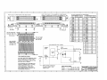
The logic interface to the carrier board is made through
connector P1 (refer to Table 2.2). P1 also provides +5V to power
the module (the ±12V lines are not used). Not all of the IP logic P1
pin functions are used.
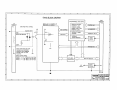
A programmable logic device installed on the IP Module
provides the control signals required to operate the board. It
decodes the selected addresses in the I/O, Interrupt, and ID spaces
and produces the chip selects, control signals, and timing required
by the control registers, as well as, the acknowledgement signal
required by the carrier board per the IP specification. It also stores
the interrupt vector and controls whether event interrupts will drive
the carrier board interrupt request line.
The ID PROM (read only) is implemented in the PLD installed
on the IP module and provides the identification for the individual
module per the IP specification. The ID PROM & configuration and
control registers are all accessed through an 8-bit data bus interface
to the carrier board.
5.0 SERVICE AND REPAIR
SERVICE AND REPAIR ASSISTANCE
Surface-Mounted Technology (SMT) boards are generally
difficult to repair. It is highly recommended that a non-functioning
board be returned to Acromag for repair. The board can be easily
damaged unless special SMT repair and service tools are used.
Further, Acromag has automated test equipment that thoroughly
checks the performance of each board. When a board is first
produced and when any repair is made, it is tested, placed in a burnin room at elevated temperature, and retested before shipment.
Please refer to Acromag's Service Policy Bulletin or contact
Acromag for complete details on how to obtain parts and repair.
PRELIMINARY SERVICE PROCEDURE
Before beginning repair, be sure that all of the procedures in
Section 2, Preparation For Use, have been followed. Also, refer to
the documentation of your carrier board to verify that it is correctly
configured. Replacement of the module with one that is known to
work correctly is a good technique to isolate a faulty module.
CAUTION: POWER MUST BE TURNED OFF BEFORE
REMOVING OR INSERTING BOARDS
Acromag’s Application Engineers can provide further technical
assistance if required. When needed, complete repair services are
also available from Acromag.
- 14 -