1
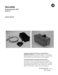
Allen-Bradley DeviceNet Starter Kit (Cat. No. 1787-STARTKIT1) User Manual Important User Information Solid state equipment has operational characteristics differing from those of electromechanical equipment. “Safety Guidelines for the Application, Installation and Maintenance of Solid State Controls” (Publication SGI-1.1) describes some important differences between solid state equipment and hard–wired electromechanical devices. Because of this difference, and also because of the wide variety of uses for solid state equipment, all persons responsible for applying this equipment must satisfy themselves that each intended application of this equipment is acceptable. In no event will the Allen-Bradley Company be responsible or liable for indirect or consequential damages resulting from the use or application of this equipment. The examples and diagrams in this manual are included solely for illustrative purposes. Because of the many variables and requirements associated with any particular installation, the Allen-Bradley Company cannot assume responsibility or liability for actual use based on the examples and diagrams. No patent liability is assumed by Allen-Bradley Company with respect to use of information, circuits, equipment, or software described in this manual. Reproduction of the contents of this manual, in whole or in part, without written permission of the Allen-Bradley Company is prohibited. Throughout this manual we use notes to make you aware of safety considerations. ! ATTENTION: Identifies information about practices or circumstances that can lead to personal injury or death, property damage, or economic loss. Attentions help you: • identify a hazard • avoid the hazard • recognize the consequences Important: Identifies information that is especially important for successful application and understanding of the product. PLC, PLC-5, SLC, SLC 500, SLC 5/02, SLC 5/03, SLC 5/04, 800T RediSTATION, DeviceLink and DeviceNetManager are trademarks of Allen-Bradley Company, Inc. IBM is a registered trademark of International Business Machines, Incorporated. Microsoft is a registered trademark of Microsoft Corporation. Windows, Windows 95 and Windows NT are trademarks of Microsoft Corporation. DeviceNet is a trademark of the Open DeviceNet Vendor Association (O.D.V.A.). Table of Contents Before You Begin Chapter 1 What this Chapter Contains . . . . . . . . . . . . . . . . . . . . . . . . . . . . . What Is DeviceNet? . . . . . . . . . . . . . . . . . . . . . . . . . . . . . . . . . . . What Hardware and Software You Need to Make Use of Your Starter Kit . . . . . . . . . . . . . . . . . . . . . . . . What We Assume You Know and Have Done . . . . . . . . . . . . . . . . . Tool You Must Provide . . . . . . . . . . . . . . . . . . . . . . . . . . . . . . . . . Identify the Starter Kit Components . . . . . . . . . . . . . . . . . . . . . . . . Identify the Components You Must Provide . . . . . . . . . . . . . . . . . . What You Will Be Doing in this Manual . . . . . . . . . . . . . . . . . . . . . Complete the Starter Kit Survey Diskette . . . . . . . . . . . . . . . . . . . . Rely on A-B Quality and DeviceNet Support . . . . . . . . . . . . . . . . . . Related Publications . . . . . . . . . . . . . . . . . . . . . . . . . . . . . . . . Summary and What’s Next . . . . . . . . . . . . . . . . . . . . . . . . . . . . . . Connect the Physical Media Chapter 2 Set Up an Online Connection Chapter 3 What this Chapter Contains . . . . . . . . . . . . . . . . . . . . . . . . . . . . . Illustrated Objective . . . . . . . . . . . . . . . . . . . . . . . . . . . . . . . . . . . Connect the Trunkline . . . . . . . . . . . . . . . . . . . . . . . . . . . . . . . . . Connect the Drop Lines . . . . . . . . . . . . . . . . . . . . . . . . . . . . . . . . Summary and What’s Next . . . . . . . . . . . . . . . . . . . . . . . . . . . . . . What this Chapter Contains . . . . . . . . . . . . . . . . . . . . . . . . . . . . . Illustrated Objective . . . . . . . . . . . . . . . . . . . . . . . . . . . . . . . . . . . Connect the 1770-KFD and Personal Computer . . . . . . . . . . . . . . . Connect the 1747-SDN Scanner Module . . . . . . . . . . . . . . . . . . . . Connect the Power Supply . . . . . . . . . . . . . . . . . . . . . . . . . . . . . . Ground the Starter Kit . . . . . . . . . . . . . . . . . . . . . . . . . . . . . . . . . Apply System Power . . . . . . . . . . . . . . . . . . . . . . . . . . . . . . . . . . Check Scanner Module Diagnostics . . . . . . . . . . . . . . . . . . . . . Set Up an On-line Connection . . . . . . . . . . . . . . . . . . . . . . . . . . . . Perform a Network Who . . . . . . . . . . . . . . . . . . . . . . . . . . . . . . . . Summary and What’s Next . . . . . . . . . . . . . . . . . . . . . . . . . . . . . . 1–1 1–1 1–2 1–2 1–3 1–3 1–3 1–4 1–4 1–5 1–5 1–6 2–1 2–1 2–2 2–3 2–4 3–1 3–1 3–2 3–3 3–4 3–5 3–5 3–6 3–6 3–9 3–10 Publication DN-6.9.1 – June 1996 ii Connect the Devices and Perform Node Commissioning Chapter 4 Configure and Monitor the Devices with DeviceNetManager Chapter 5 Use APS and DeviceNetManager for Control and Diagnostics Chapter 6 Publication DN-6.9.1 – June 1996 What this Chapter Contains . . . . . . . . . . . . . . . . . . . . . . . . . . . . . Illustrated Objective . . . . . . . . . . . . . . . . . . . . . . . . . . . . . . . . . . . Configure the 800T RediSTATION . . . . . . . . . . . . . . . . . . . . . . . . . Connect the 800T RediSTATION . . . . . . . . . . . . . . . . . . . . . . . . . . Check the Node Address of the RediSTATION . . . . . . . . . . . . . . Connect the Series 9000 Photoelectric Sensor . . . . . . . . . . . . . . . . Check the Node Address of the Photoelectric Sensor . . . . . . . . . Perform Node Commissioning . . . . . . . . . . . . . . . . . . . . . . . . . Connect the DeviceLink I/O and Limit Switch . . . . . . . . . . . . . . . . . Check the Node Address of the DeviceLink I/O . . . . . . . . . . . . . Perform Node Commissioning . . . . . . . . . . . . . . . . . . . . . . . . . Summary and What’s Next . . . . . . . . . . . . . . . . . . . . . . . . . . . . . . What this Chapter Contains . . . . . . . . . . . . . . . . . . . . . . . . . . . . . Configure the Series 9000 Photoelectric Sensor . . . . . . . . . . . . . . . Monitor the Status of the Photoelectric Sensor . . . . . . . . . . . . . . . . Configure the DeviceLink I/O . . . . . . . . . . . . . . . . . . . . . . . . . . . . Monitor the Status of the DeviceLink I/O . . . . . . . . . . . . . . . . . . . . Configure the 1747-SDN Scanner Module . . . . . . . . . . . . . . . . . . . Summary and What’s Next . . . . . . . . . . . . . . . . . . . . . . . . . . . . . . What this Chapter Contains . . . . . . . . . . . . . . . . . . . . . . . . . . . . . Create the Ladder Logic Program . . . . . . . . . . . . . . . . . . . . . . . . . Use APS and DeviceNet Manager to Perform and Monitor DeviceNet Control and Diagnostics . . . . . . . . . . . . . . . . . . . . . . . . . . . . . Rung 0 . . . . . . . . . . . . . . . . . . . . . . . . . . . . . . . . . . . . . . . . . . Rung 2 . . . . . . . . . . . . . . . . . . . . . . . . . . . . . . . . . . . . . . . . . . Rung 3 . . . . . . . . . . . . . . . . . . . . . . . . . . . . . . . . . . . . . . . . . . Rung 4 . . . . . . . . . . . . . . . . . . . . . . . . . . . . . . . . . . . . . . . . . . Summary . . . . . . . . . . . . . . . . . . . . . . . . . . . . . . . . . . . . . . . . . . 4–1 4–1 4–2 4–3 4–4 4–5 4–6 4–6 4–9 4–10 4–10 4–13 5–1 5–1 5–4 5–5 5–7 5–8 5–13 6–1 6–2 6–4 6–4 6–4 6–5 6–6 6–7 Chapter 1 What this Chapter Contains This chapter describes what you must know and do before you begin to use your starter kit. The following table describes what this chapter contains and its location. For information about DeviceNetTM network what you need to use this starter kit what we assume you know and have done identifying the starter kit components identifying what components you must provide what you will be doing in this manual completing the survey diskette Allen-Bradley quality and DeviceNet support chapter summary and what’s next What Is DeviceNet? See page 1–1 1–2 1–2 1–3 1–3 1–4 1–4 1–5 1–6 DeviceNet is a low-end, open network providing connections between simple, primarily discrete industrial devices and controllers without the need for intervening I/O modules or blocks. Simple devices include products such as sensors and actuators. The intent of this network is to provide an alternate way for control engineers to connect simple devices to their control systems. The DeviceNet network: • supports devices that are becoming more intelligent • facilitates increasingly precise troubleshooting to reduce down-time (a communication fault can be traced to a single device rather than to the rack or block level as with an I/O network) • reduces installation and startup costs and time (compared to traditional I/O wiring, especially when devices are spread over several hundred feet) Publication DN-6.9.1 – June 1996 1–2 Before You Begin What Hardware and Software You Need for Your Starter Kit The following table lists what materials you need to follow the procedures described in this manual. Notice which products are supplied in the DeviceNet starter kit and which you must provide. Product Quantity Part number Provided in the Starter Kit 1 T-port tap (right keyway) mini-male to conductor 1m drop cable mini-male to micro female 1m drop cable terminator, female 3-receptacle 5-wire terminal block DeviceLink I/O mini-male to mini female limit switch, mini-male Series 9000 Diffuse Photoelectric sensor 800T RediSTATION this user manual Feedback Disk with DeviceNet survey 5 4 4 2 1 1 1 1 1 1 1 1485P-P1N5-MN5R1 1485R-P1M5-C 1485R-P1M5-R5 1485A-T1N5 1492-DNTB3 1485D-A1M5-R4 802T-APJ1 42GNP-9000-QD 2705-T3DN1A42A DN-6.91 CSV-683 What You Must Provide 24 volt, DC power supply (<3amp output) wires for power supply (18 gauge recommended) SLC chassis SLC 5/02, 5/03, or 5/04 processor SLC DeviceNet scanner1 SLC chassis power supply SLC programming software2 IBM compatible PC Microsoft WindowsTM (3.1 or later), Windows NTTM or Window ’95TM software DeviceNetManager TM software1 RS-232 interface module1 PC-to-SLC programming connection3 1 3 1 1 1 1 1 1 1 1 1 1 n/a n/a 1746-A4, -A7, -A10, -A13 1747-L524, -L532, -L542 1747-SDN 1746-P1, -P2, -P3, -P4 APS or AI5 n/a n/a 1787-MGR 1770-KFD n/a3 1 This product is included with DeviceNet Starter Kit 2 or 3. 2 APS software is used in this manual’s examples. 3 Due to the varied possibilities, the components for your PC-to-processor communication link do not appear in the table above or the following illustrations. Your existing PC-to-processor connection is compatible with this document’s procedures and configurations. Important: You can use this starter kit with a PLC chassis, processor and 1771-SDN scanner module. Differences are based on PLC technology (scanner mapping and PLC programming). These variations are described where applicable in this user manual. You can use this starter kit with any DeviceNet master. Refer to your user documentation for more information. What We Assume You Know and Have Done The descriptions in this user manual assume that you know how to install and use all of the hardware and software that you must provide (listed above). We also assume you have these items installed and ready. If you do not, read the documentation associated with these items and have them installed and ready to use before you attempt to assemble your starter kit. Publication DN-6.9.1 – June 1996 Before You Begin 1–3 Tool You Must Provide To connect the wiring in this starter kit, you’ll need a small, flat-blade screwdriver. Identify the Starter Kit Components Unpack your starter kit and use the following illustration to identify all of the components you should have received. Contact your local Allen-Bradley representative if any item is missing. Î Î Î ÎÎ ÎÎ T-port tap (5) Î Î ÎÎ ÎÎ Mini-male to conductor, 1m drop (2) 3-receptacle 5-wire terminal block (1) ÎÎ Mini-male to micro-female (1) Î Î DeviceLink I/O mini-male to mini-female (1) Female terminator (2) Limit switch mini-male (1) ÎÎ ÎÎ ÎÎ ÎÎ ÎÎ This user manual (1) 800T RediSTATION with mini-male connector (1) Series 9000 Photoelectric sensor micro-male (1) floppy disk with survey (1) Identify the Components You Must Provide Use the following illustration to identify all of the hardware and software you must provide. SLC 5/02, 5/03 or 5/04 Processor 24 Volt, DC power supply with three wires (18-gauge recommended) 1747-SDN DeviceNet Scanner Module* 5-pin linear plug with probe holes and jack screws (included with 1747-SDN Scanner Module)* Power Supply SLC chassis 1770-KFD Interface Module* DeviceNetManager Software* SLC Programming Software* * Included with Starter Kit 2 or 3. PC with Windows (3.1) and programming software installed 5-pin linear plug with probe holes (included with 1770-KFD module)* Publication DN-6.9.1 – June 1996 1–4 Before You Begin What You Will Be Doing in this Manual Start Complete The following chapters describe how to setup up a simple DeviceNet network and perform basic operations: Chapter 1 Chapter 2 Chapter 3 Before You Begin Connect the Physical Media Set Up an Online Connection Chapter 6 Chapter 5 Chapter 4 Use APS and DeviceNet Manager Configure the Devices with DeviceNet Manager Connect Devices and Commission Nodes Complete the Starter Kit Feedback Disk Your starter kit contains a Feedback Disk with a Windows-based survey. This survey is designed to get your comments on the starter kit, the DeviceNet network and Allen-Bradley products and services. We will use your input for future product and service development. Feedback Disk Please complete the survey by answering all the questions, enclosing the disk in the self-addressed stamped envelope and mailing it. Allen-Bradley guarantees complete confidentiality of all information on the survey disk. DeviceNet Business Reply Mail self-addressed return envelope Publication DN-6.9.1 – June 1996 Before You Begin Rely on A-B Quality and DeviceNet Support 1–5 We have helped numerous customers around the world achieve their manufacturing goals. For assistance with A-B DeviceNet products, call your local distributor or sales office. Our support network offers complete system integration and support services including application engineering, installation supervision, system startup, training, field service, and ongoing product support. We’re global because we’re local to you. You can access an A-B sales representative, appointed distributor, or authorized system integrator almost anywhere around the world. Perhaps that’s why A-B is the preferred supplier of automation controls in the industry. Related Publications Title Publication Number DN-2.5 DeviceNet Product Overview DeviceNet Sealed Physical Media Bulletin 1485 Product Profile DeviceNet Media System Vendor List PHOTOSWITCH Series 9000 Photoelectric Sensors for the DeviceNet Network Product Profile DeviceNet RediSTATION Product Profile DeviceNet Communication Link Overview Product Profile DeviceLink I/O Product Profile DeviceNet Scanner for 1771 Chassis Product Profile Open DeviceNet Vendor Association Catalog Open Device Network Offers Improved Communications and Flexibility Product Profile DN-1.8 DN-2.1 DN-1.11 DN-1.13 DN-1.18 DN-1.15 DN-1.7 CSV-654 DN-1.9 Publication DN-6.9.1 – June 1996 1–6 Before You Begin Summary and What’s Next In this chapter, you learned: • about the DeviceNet network • what you need to use this starter kit • what we assume you know and have done • to identify the starter kit components • to identify the components you must provide • what you will be doing in this manual • how to complete the starter kit survey diskette • about Allen-Bradley quality and DeviceNet support Move on to Chapter 2 to learn how to connect the physical media. Publication DN-6.9.1 – June 1996 Chapter 2 Connect the Physical Media What this Chapter Contains The following table describes what this chapter contains and its location. For information about: what the network will look like connecting the trunk line connecting the drop lines chapter summary and what’s next Illustrated Objective female terminating resistor Use the illustration below to see how your DeviceNet network will look after following this chapter’s procedures. Ï Ï ÏÏ Ï ÏÏÏÏÏÏÏÏ Ï ÏÏ T-port tap T-port tap 3-receptacle, 5-wire terminal block Mini-male to open conductor mini-male to micro-female drop line ÏÏ See page 2–1 2–2 2–3 2–4 Ï ÏÏ Ï Ï Ï ÏÏÏÏÏÏÏÏÏ ÏÏ ÏÏ T-port tap T-port tap T-port tap female terminating resistor Mini-male to open conductor Mini-male to open conductor drop lines (2) 5-pin linear plug 5-pin linear plug with jack screws Publication DN-6.9.1 – June 1996 2–2 Connect the Physical Media Connect the Trunk Line Gather the following components from your starter kit: Ï Ï ÏÏ Ï Ï ÏÏ Ï Ï ÏÏ ÏÏ ÏÏ Ï Ï Ï Ï Ï Ï Ï Ï Female terminators (2) T-port taps (5) Mini-male to open conductors (2) Ï Ï ÏÏ ÏÏ 3-receptacle 5-wire terminal block (1) Use the following illustration as a guide to connect the trunk line: Basic steps 1. Insert and hand-tighten the T-port taps to each other in groups of two and three. 2. Connect colored wiring on open conductors to matching terminals on the terminal block. 3. Attach terminators to each end of the row of T-port taps. How to wire the terminal block: 2nd terminal strip and receptacle (center and rear) RED WHITE DRAIN BLUE BLACK Important When terminating a DeviceNet system, do not put a terminating resistor on a node. Doing so risks network failure if you remove the node. The resistor must be at the end of the trunk line. female terminating resistor 1st terminal strip and receptacle (left) Ï Ï Ï Ï ÏÏÏ Ï Ï ÏÏ Ï T-port tap RED WHITE DRAIN BLUE BLACK Ï Ï T-port tap terminal block Mini-male to open conductor ÏÏ ÏÏ Mini-male to open conductor Connect this T-port tap to this mini-male connector Ï Ï Ï ÏÏ ÏÏÏ ÏÏÏ ÏÏÏ ÏÏ T-port tap Publication DN-6.9.1 – June 1996 T-port tap T-port tap female terminating resistor Prepare Your Physical Media Connect the Drop Lines 2–3 To connect the drop lines, gather the following components: ÏÏ ÏÏÏÏ Included with your starter kit Included with your 1770-KFD module 5-pin linear plug Mini-male to open conductor drop lines (2) mini-male to micro-female drop line Included with your 1747-SDN module 5-pin linear plug with jack screws ÏÏ Use the following illustration as a guide to attach the drop lines to the trunk line: Ï ÏÏ Ï ÏÏÏÏÏÏÏÏ ÏÏ T-port tap female terminating resistor T-port tap terminal block Mini-male to open conductor Ï Ï Ï ÏÏ ÏÏÏÏÏÏÏÏÏÏÏ ÏÏ ÏÏ T-port tap T-port tap T-port tap female terminating resistor Mini-male to open conductor Mini-male to open conductor drop lines (2) mini-male to micro-female drop line 5-pin linear plug Ï Ï 5-pin linear plug with jack screws Basic steps 1. Insert and hand-tighten each conductor of a mini-male-to-conductor drop line into the appropriate T-port tap. 2. Wire the 5-pin linear plug according to the illustration on the right. Make sure the wiring color sequence matches the color sequence on the label of the 1770-KFD module. 3. How to wire the 5-pin linear plugs: BLACK BLUE DRAIN WHITE RED RED BLUE WHITE DRAIN BLACK Wire the 5-pin linear plug with jack screws according to the illustration on the right. Make sure the wiring color sequence matches the color sequence on the label of the 1747-SDN module. Publication DN-6.9.1 – June 1996 2–4 Connect the Physical Media Summary and What’s Next Publication DN-6.9.1 – June 1996 In this chapter, you learned how to: • understand what the network will look like • connect the trunk line components • connect the drop lines Move on to Chapter 3 to learn how to set up an online connection. Chapter 3 Set Up an Online Connection What this Chapter Contains The following table describes what this chapter contains and its location. For information about: what the network will look like connecting the 1747-SDN scanner module connecting the power supply grounding the network applying system power setting up an online connection performing a Network Who chapter summary and what’s next Illustrated Objective ÎÎÎÎÎÎÎ ÎÎ ÎÎ See page 3–1 3–3 3–4 3–5 3–5 3–6 3–9 3–10 Use the illustration below to see how your DeviceNet network will look after following this chapter’s procedures. ÎÎ ÎÎ Î Î Î Î ÎÎ Publication DN-6.9.1 – June 1996 3–2 Set Up an Online Connection Connect the 1770-KFD and Personal Computer To connect the 1770-KFD interface module: 1. Use the RS-232 cable to connect the 1770-KFD module to your computer’s serial port. ÎÎ Î 1770-KFD interface module RS-232 Cable to your computer Drop line RS-232 2. Use one of the 5-pin linear plugs (attached to the mini-male to open conductor) to connect the 1770-KFD module to the trunk line. RS-232 Cable Mini-male to open conductor with 5-pin linear plug attached 1770-KFD interface module ÎÎ Î Drop line Mini-male to open conductor with 5-pin linear plug attached. Be sure the wiring orientation on the plug matches the wiring color scheme on the 1770-KFD module. Publication DN-6.9.1 – June 1996 Set Up an Online Connection Connect the 1747-SDN Scanner Module For installation information on the 1771-SDN scanner module, refer to the Installation Instructions, publication 1771-5.14. ÎÎ Î ÎÎ ÎÎ Î ÎÎ ÎÎÎÎÎÎÎ Î 3–3 To connect the scanner module: 1. Be sure that the SLC chassis power is off. ! ATTENTION: Do not wire the 1747-SDN Scanner Module with the network power supply on. Wiring the module with the network power supply on may short your network or disrupt communication. 2. Connect the 1747-SDN Scanner Module to the 5-pin linear plug (attached to the mini-male open conductor) as shown in the area of detail below: Î Î Î Î ÎÎÎÎÎÎÎÎÎÎ ÎÎ ÎÎ Drop line SLC chassis Chassis Power Supply 1747-SDN DeviceNet Scanner Module SLC 5/02, -5/03 or -5/04 Processor Mini-male to open conductor with 5-pin linear plug with jack screws. DeviceNet port 5-pin linear plug Be sure the wiring orientation on the plug matches the wiring color scheme on the 1747-SDN Scanner Module module. 3. Tighten the jack screws on the 5-pin linear plug. Publication DN-6.9.1 – June 1996 3–4 Set Up an Online Connection Connect the Power Supply Connect the 24Vdc power supply to the terminal block as shown in the area of detail below: ATTENTION: The cabling in the DeviceNet starter kit is rated at 3 amps. Be sure your power supply output current does not exceed 3 amps. ! RED (24Vdc) RAIL 3 DRAIN (GND) BLACK (0Vdc) RAIL 3 To power source 3rd terminal strip and receptacle (right and front) 24Vdc power supply ÎÎÎÎÎÎ ÎÎ ÎÎ ÎÎ Publication DN-6.9.1 – June 1996 ÎÎÎ Î Î Î ÎÎ ÎÎ ÎÎ ÎÎ ÎÎ ÎÎ Set Up an Online Connection Ground the Network 3–5 You must ground your DeviceNet network at only one location. schematic To ground the network: signal signal drain V– V+ • Connect the network shield and drain wire to an earth or building ground using a 0.25mm (1in) copper braid or a #8 AWG wire up to 3m (10ft) maximum in length • Use the same ground for the V– conductor of the cable system and the dc ground of the power supply. V– V+ class 2 power supply L1 L2 grd 120V ac (typical) Apply System Power Apply power to the devices you just installed in your DeviceNet system: • 24V dc power supply • 1770-KFD interface module • personal computer • SLC chassis with power supply and scanner module installed 24Vdc power supply ÎÎÎÎ ÎÎÎ ÎÎÎÎÎÎ ÎÎ Î ÎÎ ÎÎÎÎ 1770-KFD interface module Personal Computer Power Supply 1747-SDN DeviceNet Scanner Module SLC 5/02, 5/03 or 5/04 Processor Publication DN-6.9.1 – June 1996 3–6 Set Up an Online Connection Check Scanner Module Diagnostics Observe the diagnostics on the scanner module: • the node address and status display should be alternately flashing between 00 and 75 • the module status indicator should illuminate solid green • the network status should be flashing green Top part of module DeviceNet STATUS MODULE NET Node Address and Status Display ADDRESS/ERROR Set Up an On-line Connection Follow these steps to go on line: 1. Start DeviceNetManager software. 2. From the Utilities menu, choose Set Up Online Connection. For installation information on DeviceNetManager Software, refer to the DeviceNetManager User Manual, publication 1787-6.5.3. Publication DN-6.9.1 – June 1996 Set Up an Online Connection 3–7 You see this screen: The node address for the 1770-KFD module should be 62. Is the Node Address for your 1770-KFD 62? Yes No Choose the new address by scrolling to 62 in the Node Address dialog box: Change your project path. and then: You see this screen: Publication DN-6.9.1 – June 1996 3–8 Set Up an Online Connection 3. Choose You see this status bar at the bottom of the Program Manager screen: The status bar indicates you are online. If you see this screen: For troubleshooting information on DeviceNetManager Software, refer to the DeviceNetManager User Manual, publication 1787-6.5.3. check your network connections and repeat the Set Up Online Connection procedure. Publication DN-6.9.1 – June 1996 Set Up an Online Connection Perform a Network Who 3–9 Perform a Network Who to verify that the 1747-SDN Scanner Module and DeviceNetManager software are on the network. 1. From the Who menu, select Network Who. You see this screen: 2. After the 1747-SDN Scanner Module and DeviceNetManager software devices appear on the network, click on If one or both of the devices do not appear, check their connections and repeat the Network Who procedure. Publication DN-6.9.1 – June 1996 3–10 Set Up an Online Connection Summary and What’s Next In this chapter, you learned how to: • connect the 1770-KFD and your personal computer • connect the 1747-SDN scanner module • connect the power supply • ground the network • apply system power • set up an on-line connection • perform a Network Who • chapter summary and what’s next Move on to Chapter 4 to learn how to connect the devices. Publication DN-6.9.1 – June 1996 Chapter 4 Connect the Devices and Perform Node Commissioning What this Chapter Contains The following table describes what this chapter contains and its location. For information about: what the network will look like configuring the 800T RediSTATION operator interface connecting the 800T RediSTATION operator interface connecting the Series 9000 photoelectric sensor and performing node commissioning connecting the DeviceLink I/O and limit switch and performing node commissioning chapter summary and what’s next Illustrated Objective 4–5 4–9 4–13 Use the illustration below to see how your DeviceNet network will look after following this chapter’s procedures. ÎÎ ÎÎ Î ÎÎÎÎÎÎÎ DeviceLink I/O Drop line Series 9000 Photoelectric sensor micro-male See page 4–1 4–2 4–3 Î Î Î Î ÎÎÎÎÎÎÎÎÎÎ 800T RediSTATION operator interface with mini-male connector Î Î Limit switch mini-male Publication DN-6.9.1 – June 1996 4–2 Connect the Devices and Perform Node Commissioning Configure the 800T RediSTATION Operator Interface baud output rate flash rate 1 2 3 4 5 6 7 8 9 10 ON = 1 OFF = 0 node address You must configure the RediSTATION operator interface’s DIP switches before it can go online. This configuration is its commissioning. The RediSTATION operator interface is not commissioned through the software. Switch-configured values include: • node address • baud rate • output fault-state • output flash-rate To configure your RediSTATION operator interface: output fault state 1. Remove the RediSTATION operator interface’s enclosure cover: A. Using a slotted screwdriver, remove the six cover screws. B. Carefully remove the cover so as not to disconnect any wires. C. To easily access the DIP switches, disconnect the 5-pin linear plug from the circuit board. 6 Cover Screws 2. Set the DIP switches to match the illustration below. ! ATTENTION: Do not use a pencil to set the RediSTATION operator interface’s DIP switches. Graphite from the pencil is conductive and may damage the switch. DIP Switches 1 2 3 4 5 6 7 8 9 10 ON = 1 OFF = 0 5-pin linear plug LED Cover In this manual’s example, these dip switch settings indicate that: • the node address is 15 • the baud rate is 125 Kb • the output fault-state is off • the output flash rate is 1 hz (0.5 seconds on and 0.5 seconds off) 3. Re-attach the 5-pin linear plug to the circuit board. 4. Use the six cover screws to re-attach the enclosure to the station’s cover. For more detailed information about setting DIP switches, refer to the RediSTATION Operator Interface User Manual. DeviceNet Connector Publication DN-6.9.1 – June 1996 Connect the Devices and Perform Node Commissioning Connect the 800T RediSTATION Operator Interface Î Î Î ÎÎÎÎÎÎÎ 4–3 Connect the 800T RediSTATION operator interface to the mini-female end of the T-port connector as shown in the area of detail below: ÎÎ ÎÎ Î Î ÎÎÎÎÎÎÎÎÎÎ 800T RediSTATION operator interface with mini-male connector Publication DN-6.9.1 – June 1996 4–4 Connect the Devices and Perform Node Commissioning Check the Node Address of the RediSTATION Operator Interface 1. From the Who menu, select Network Who. You see this screen: 2. After all three devices appear, click on The node address for the RediSTATION operator interface is 15. You configured this node address on page 4–2. 3. Click on Publication DN-6.9.1 – June 1996 Connect the Devices and Perform Node Commissioning Connect the Series 9000 Photoelectric Sensor 4–5 Connect the Series 9000 Photoelectric Sensor to the micro-female end of drop line as shown in the area of detail below: ÎÎ Î ÎÎ ÎÎ Î ÎÎ ÎÎÎÎÎÎÎ Î Î Î Î Î Î ÎÎÎÎÎÎÎÎÎÎ ÎÎ ÎÎ Drop line mini-male to micro-female conductor Î Î Series 9000 Photoelectric sensor micro-male After you connect the photoelectric sensor to the network, look for the illuminated and flashing indicators that indicate the sensor is functioning. Top of Photo sensor Front of Photo sensor yellow - output green - margin red/green - status Pass your hand in front of the sensor’s eye to block it. Observe how the indicators change as you pass your hand back and forth. Publication DN-6.9.1 – June 1996 4–6 Connect the Devices and Perform Node Commissioning Check the Node Address of the Photoelectric Sensor 1. If you have not already done so, refer to Chapter 3 to set up an online connection. 2. From the Who menu, select Network Who. You see this screen: 3. After all four devices appear, click on The node address for the photoelectric sensor should be 63. The following steps show you how to use DeviceNetManager to change the node address to 07. 4. Click on Perform Node Commissioning Commission the node to change the node address. 1. From the Utilities menu, select Publication DN-6.9.1 – June 1996 Connect the Devices and Perform Node Commissioning 4–7 You see this screen: 2. In the Current Device Settings dialog box, scroll to the node address you want to change (in this example, 63). 3. In the New Device Settings dialog box, scroll to 07. 4. Click on The status bar indicates Transaction Completed : Status 5. Click on to verify the address has changed. Publication DN-6.9.1 – June 1996 4–8 Connect the Devices and Perform Node Commissioning You see this screen: 6. After all four devices appear, click on 7. Verify that the node address for the photoelectric sensor has changed from 63 to 07. Publication DN-6.9.1 – June 1996 8. Click on to close network who. 9. Click on to close node commissioning. Connect the Devices and Perform Node Commissioning Connect the DeviceLink I/O and Limit Switch 4–9 Connect the DeviceLink I/O (with the limit switch attached) to the trunk line as shown in the area of detail below: Î Î Î ÎÎÎÎÎÎÎ ÎÎ ÎÎ ÎÎ ÎÎ Î Î ÎÎÎÎÎÎÎÎÎÎ Î ÎÎ DeviceLink I/O mini-male to mini-female ÎÎ ÎÎ ÎÎ Limit switch mini-male After you connect the DeviceLink I/O to the network, look for the flashing green LED that indicates the device is functioning. ÎÎ green LED ÎÎ ÎÎ Publication DN-6.9.1 – June 1996 4–10 Connect the Devices and Perform Node Commissioning Check the Node Address of the DeviceLink I/O 1. From the Who menu, select Network Who. You see this screen: 2. After all five devices appear, click on 3. Click on Perform Node Commissioning You must change the node address for the DeviceLink I/O to 10. Commission the node to change the node address. 1. From the Utilities menu, select Publication DN-6.9.1 – June 1996 Connect the Devices and Perform Node Commissioning 4–11 You see the Device Configuration Node Commissioning screen: 2. In the Current Device Settings dialog box, scroll to the node address you want to change (the incorrect node address number for the DeviceLink I/O). In this example, the number is 63. 3. In the New Device Settings dialog box, scroll to 10. 4. Click on The status bar indicates Transaction Completed : Status 5. Click on to verify the address has changed. Publication DN-6.9.1 – June 1996 4–12 Connect the Devices and Perform Node Commissioning You see this screen: 6. After all five devices appear, click on 7. Verify that the node address for the DeviceLink I/O has changed from 63 to 10. Publication DN-6.9.1 – June 1996 8. Click on to close network who. 9. Click on to close node commissioning. Connect the Devices and Perform Node Commissioning Summary and What’s Next 4–13 In this chapter, you learned how to: • understand what the network should look like • configure the 800T RediSTATION operator interface • connect the 800T RediSTATION operator interface • connect the Series 9000 photoelectric sensor and perform node commissioning • connect the DeviceLink I/O and limit switch and perform node commissioning Move on to Chapter 5 to learn how to configure and monitor devices with the DeviceNetManager software. Publication DN-6.9.1 – June 1996 4–14 Connect the Devices and Perform Node Commissioning Publication DN-6.9.1 – June 1996 Chapter 5 Configure and Monitor the Devices with DeviceNetManager Software What this Chapter Contains The following table describes what this chapter contains and its location. For information about: configuring the Series 9000 photoelectric sensor configuring the DeviceLink I/O configuring the 1747-SDN Scanner Module chapter summary and what’s next Configure the Series 9000 Photoelectric Sensor See page 5–1 5–5 5–8 5–13 Use DeviceNetManager software to change the configuration of the photoelectric sensor: 1. From the Who menu, select Network Who. You see this screen: 2. After all five devices appear, click on 3. Double-click on the Photoelectric Sensor to open its Device Configuration – Enhanced Mode screen. Publication DN-6.9.1 – June 1996 5–2 Configure and Monitor the Devices with DeviceNetManager Software You see this screen: The photoelectric sensor supports these three parameters. Operate Mode is the only configurable parameter. Output and Operating Margin are ‘‘read only” as indicated by the letter ‘‘R.” The sensor is configured for Light Operate. 4. To verify this, pass your hand in front of the sensor and you see that the output (yellow) and margin (green) indicators illuminate. This indicates that the sensor is in Light Operate mode. Top of photoelectric sensor Front of photoelectric sensor These indicators illuminate when the photoelectric sensor detects an object. yellow - output green - margin red/green - status 5. To change this parameter from Light Operate to Dark Operate, first highlight the Output Mode parameter as shown in the above screen, then click on You see this screen: 6. In the Settings dialog box, click in the Dark Operate radio button. Publication DN-6.9.1 – June 1996 Configure and Monitor the Devices with DeviceNetManager Software 5–3 You see the Dark Operate area become highlighted: 7. Click on 8. Click on The Parameters dialog box shows that the mode has changed from light to dark operate: 9. To verify this, pass your hand in front of the photoelectric sensor. When the photoelectric sensor detects your hand, the output indicator (yellow) goes off and the margin indicator (green) goes on. This indicates that the sensor is in Dark Operate mode. Top of photoelectric sensor Front of photoelectric sensor green - margin yellow - output red/green - status 10.To return to Light Operate mode, repeat steps 5–8 and select Light Operate. 11. To close the Device Configuration screen, click on Publication DN-6.9.1 – June 1996 5–4 Configure and Monitor the Devices with DeviceNetManager Software Monitor the Status of the Photoelectric Sensor To monitor the status of the photoelectric sensor: 1. In the Device Configuration screen, click on You see how the DeviceNet Manager software monitors and reports status: • Status flashes Monitoring • Parameters are repeatedly scanned • Value reports current status 2. Hold your hand in front on the photoelectric sensor. You see how the Output Value changes: • Output goes from On to Off 3. Use your thumb to cover part one of the lenses on the photoelectric sensor. You see how the Operating Margin Value changes: • Operating Margin goes from OK to Low Margin Publication DN-6.9.1 – June 1996 Configure and Monitor the Devices with DeviceNetManager Software 5–5 4. Click on 5. Click on Configure the DeviceLink I/O Continue with DeviceNetManager software to change the configuration of the DeviceLink I/O: 1. From the Network Who screen, double-click on the DeviceLink - mini to mic to open its Device Configuration – Enhanced Mode screen. You see this screen: • The On Filter Value indicates the DeviceLink default – 0ms Filter 2. To change this parameter from 0ms to 25ms, first highlight the On Filter parameter as shown in the above screen, then click on Publication DN-6.9.1 – June 1996 5–6 Configure and Monitor the Devices with DeviceNetManager Software You see this screen: 3. In the Settings dialog box, click on the 25ms Filter radio button. You see the 25ms Filter area become highlighted: 4. Click on The Parameters dialog box shows that the mode has changed from 0ms to 25ms: 5. To close the Device Configuration screen, click on Publication DN-6.9.1 – June 1996 Configure and Monitor the Devices with DeviceNetManager Software Monitor the Status of the DeviceLink I/O 5–7 To monitor the status of the DeviceLink I/O: 1. In the Device Configuration screen, click on You see how DeviceNet Manager software monitors and reports status of the DeviceLink I/O: • Status flashes Monitoring • Parameters are repeatedly scanned • Value reports current status 2. Turn and hold the switch on the limit switch. You see how the Output Value changes: • Output goes from Off to On 3. Click on 4. Click on Publication DN-6.9.1 – June 1996 5–8 Configure and Monitor the Devices with DeviceNetManager Software Configure the 1747-SDN Scanner Module Continue with DeviceNetManager software to configure the 1747-SDN Scanner Module. 1. From the Network Who screen, double-click on the 1747-SDN Scanner Module to open its Module Configuration screen. You see this screen: Specify the SLC chassis slot where the scanner module is installed. Note: If you are using a PLC-5 chassis with a 1771-SDN scanner module, select the rack/group/slot of the 1771-SDN Scanner Module. 2. In the Load From dialog box, click on 3. In the Module Settings dialog box, specify the SLC chassis slot where the scanner module is installed. 4. In the Module Settings dialog box, click on Publication DN-6.9.1 – June 1996 Configure and Monitor the Devices with DeviceNetManager Software 5–9 You see this screen: 5. Click on 6. In the Scan List Tools dialog box, click on You see this screen: Note: If you are using a 1771-SDN scanner module, the module should be mapped into Block Transfer 62 input and output. 7. Click on You see this screen: 8. Click on Publication DN-6.9.1 – June 1996 5–10 Configure and Monitor the Devices with DeviceNetManager Software You return to this screen: DeviceNet Manager software verifies that the devices have been mapped. 9. Click on You see this screen: Photoelectric Sensor Node Address 07 DeviceLink I/O Node Address 10 800T RediSTATION Node Address 15 Note: If you are using a 1771-SDN scanner module, PLC-5 data table with block transfer addresses will appear. Observe how the devices’ node addresses are assigned as inputs in the data table map. 10.In the Data Map area, click on the Output radio button. 11. Click on You return to this screen: 12.Click on Publication DN-6.9.1 – June 1996 Configure and Monitor the Devices with DeviceNetManager Software 5–11 You see that all devices are highlighted: 13.In the Save To dialog box, click on You see this screen: 14.Click on You see this screen: DeviceNet STATUS MODULE NET Node Address and Status Display 15.Click on Wait a few more moments for the download to complete. When the download is complete and the scanner has rebooted: • the scanner module alternately flashes 80 and 00 ADDRESS/ERROR Top part of module Publication DN-6.9.1 – June 1996 5–12 Configure and Monitor the Devices with DeviceNetManager Software • the DeviceLink I/O status is solid green ÎÎÎ ÎÎÎ green LED Î • the photoelectric sensor status is solid green Top of photoelectric sensor green status • the DeviceNetManager software status bar indicates Transaction Completed: Status • The Scan List Editor screen also indicates that the devices have been mapped: Devices are mapped 16.Click on Publication DN-6.9.1 – June 1996 Configure and Monitor the Devices with DeviceNetManager Software 5–13 You see this screen: 17.Click on either or We recommend that you save your scanner configuration files for future use. Summary and What’s Next In this chapter, you learned how to configure and monitor these devices using DeviceNetManager software: • Series 9000 photoelectric sensor • DeviceLink I/O • 1747-SDN Scanner Module Move on to Chapter 6 to learn how to use APS ladder logic with DeviceNetManager software. Publication DN-6.9.1 – June 1996 5–14 Configure and Monitor the Devices with DeviceNetManager Software Publication DN-6.9.1 – June 1996 Chapter 6 Use APS with the DeviceNet Starter Kit to Perform Control and Diagnostics Examples What this Chapter Contains This chapter describes how to use Advanced Programming Software (APS) with the DeviceNet Starter kit for DeviceNet control and diagnostics examples: To: create the ladder logic program use APS with DeviceNetManager to perform DeviceNet control and diagnostics examples read the chapter summary See page 6–2 6–4 6–7 To complete the tasks in this chapter, you must have: • Windows with DeviceNetManager software open • your DeviceNet network running with an online connection • APS installed Publication DN-6.9.1 – June 1996 6–2 Use APS with the DeviceNet Starter Kit to Perform Control and Diagnostics Examples Create the Ladder Logic Program Use APS to create the following ladder logic program: MOV MOVE Source Dest MOV MOVE Source Dest I:1 ] [ 16 N152:0 ] [ 10 N152:0 ] [ 7 0:1 ] [ 18 Publication DN-6.9.1 – June 1996 1 0:1.0 1 M1:1.216 * N152:0 0 0:1 ( ) 16 Use APS with the DeviceNet Starter Kit to Perform Control and Diagnostics Examples 6–3 0:1 ( ) 17 N152:0 ] [ 7 N152:0 ] [ 10 I:1 ] [ 17 I:1 ] [ 33 I:1 ] / [ 32 0:1 (L) 10 I:1 ] [ 32 I:1 ] / [ 33 0:1 (U) 18 [END OF FILE] Publication DN-6.9.1 – June 1996 6–4 Use APS with the DeviceNet Starter Kit to Perform Control and Diagnostics Examples Use the APS Ladder Program as You Perform DeviceNet Control and Diagnostics Examples Move through the APS ladder program as you perform the following DeviceNet control and diagnostics examples. Read the text descriptions of each rung as you perform these procedures: Rung 0 This rung turns on when the scanner is put in RUN mode. toggle keyswitch 1. Toggle the SLC processor keyswitch between RUN and PROGRAM. • You see the field behind the ladder rung change color 2. Put the processor in RUN mode. Rung 2 This rung turns on when the red light of the RediSTATION operator interface illuminates and/or blinks. 1. Cursor down to Rung 2, word O:1 bit 16. 2. Activate the limit switch. • You see the red light on the RediSTATION operator interface illuminate • You see the field behind the ladder rung (word O:1 bit 16) change color activate limit switch 3. Press F8 Data Monitor. 4. Again, activate the limit switch. • In the output data table, you can see word O:1 bit 16 changes from 0 to 1 5. Press place hand in front of photoelectric sensor Esc to return to the ladder program. 6. Cursor left to Rung 2, word I:1 bit 6. 7. Place your hand in front of the photoelectric sensor. • You see the red light on the RediSTATION operator interface illuminate • You see the field behind the ladder rung (word I:1 bit 16) change color Publication DN-6.9.1 – June 1996 Use APS with the DeviceNet Starter Kit to Perform Control and Diagnostics Examples 8. Press place hand in front of photoelectric sensor disconnect photoelectric sensor disconnect DeviceLink I/O ÎÎ ÎÎ Data Monitor. 9. Again, place your hand in front of the photoelectric sensor. • In the input data table, you can see word I:1 bit 16 changes from 0 to 1 10.Press Î Î Î ÎÎÎÎÎÎÎ ÎÎ ÎÎ F8 6–5 Esc to return to the ladder program. Rung 3 This rung turns on when the DeviceLink I/O and the photoelectric sensor are pulled off of the DeviceNet network, or when the photoelectric sensor is out of margin. 1. Cursor down to Rung 3, word O:1 bit 17. 2. Pull the DeviceLink I/O and the photoelectric sensor off of the DeviceNet network. • You see the red light illuminate and flash • You see the fields behind the ladder rungs (word O:1 bit 17) and (word N:152 bit 7) change color 3. Press F8 Data Monitor. 4. Press F1 Change Radix. 5. Press F1 Binary Data. • In the integer data table, you can see words 6 and 9 change from 0 to 1 6. Press Esc to return to the ladder program. 7. Cursor down to word I:1 bit 17. pull hand away from front of photoelectric sensor 8. Put your hand over the photoelectric sensor and slowly pull your hand away (out of margin) from the photoelectric sensor. • You see the 800T RediSTATION red light go out • You see the photoelectric sensor indicators go out • You see the field behind the ladder rung (word I:1 bit 17) change color Publication DN-6.9.1 – June 1996 6–6 Use APS with the DeviceNet Starter Kit to Perform Control and Diagnostics Examples 9. Press F8 Data Monitor. 10.Again, place your hand in front of the photoelectric sensor. • In the input data table, you can see word I:1 bit 17 changes from 0 to 1 pull hand away from front of photoelectric sensor 11. Again, slowly pull your hand away (out of margin) from the front of the photoelectric sensor. • In the input data table, you can see word I:1 bit 17 changes back from 1 to 0 Rung 4 This rung turns on when the red or green buttons on the RediSTATION operator interface are pushed. 1. Cursor to Rung 4, word I:1 bit 33. push green button on 800T RediSTATION operator interface 2. Push the green button on the 800T RediSTATION operator interface. • You see the red light illuminate • You see the field behind the ladder rung (word I:1 bit 33) change color 3. Press F8 Data Monitor. • In the input data table, you can see word I:1 bit 33 changes from 0 to 1 each time you push the green button 4. Cursor down to word I:1 bit 32. push red button on 800T RediSTATION operator interface 5. Push the red button on the 800T RediSTATION operator interface. • You see the red light go out • You see the field behind the ladder rung (word I:1 bit 32) change color 6. Press F8 Data Monitor. • In the input data table, you can see word I:1 bit 32 changes from 0 to 1 each time you push the red button Publication DN-6.9.1 – June 1996 7. Press Esc to return to the ladder program. 1. Press F3 to exit APS. Use APS with the DeviceNet Starter Kit to Perform Control and Diagnostics Examples Summary 6–7 In this chapter, you learned how to use APS software with DeviceNet starter kit to perform control and diagnostics: • create the ladder logic program • use APS with DeviceNetManager software to perform control and diagnostics examples Feedback disk You are done performing the tasks in this user manual. For more information on A-B DeviceNet products, call your local distributor or sales office. Please remember to complete the survey on the enclosed floppy disk. DeviceNet Business Reply Mail self-addressed return envelope Publication DN-6.9.1 – June 1996 6–8 Use APS with the DeviceNet Starter Kit to Perform Control and Diagnostics Examples Publication DN-6.9.1 – June 1996 Index Numbers C 1747-SDN scanner module. See scanner module cable system, grounding location, 3–5 1770-KFD connecting, 3–2 node address, 3–7 checking diagnostics. See diagnostics 1770-KFD interface module, applying power, 3–5 800T RediSTATION configuring, 4–2 connecting, 4–3 DIP switches, 4–2 node commissioning, 4–2 A Advanced Programming Software. See APS Allen–Bradley DeviceNet products, 7–2 network architecture, 7–3 related publications, 7–6 support services, 7–6 Allen-Bradley, DeviceNet features and benefits, 7–5 cabling, amperage rating, 3–4 configuring 800T RediSTATION, 4–2 DeviceLink I/O, 5–5 scanner module, 5–8 Series 9000 Photoelectric Sensor, 5–1 connecting 1747-SDN scanner module, 3–3 1770-KFD, 3–2 800T RediSTATION, 4–3 DeviceLink I/O, 4–9 drop lines, 2–3 limit switch, 4–9 personal computer, 3–2 physical media, 2–1 power supply, 3–4 Series 9000 Photoelectric Sensor, 4–5 trunkline, 2–2 connection, online, 3–6 control and diagnostics examples, 6–8 copying files, 6–1 amperage rating, cabling, 3–4 applying, system power, 3–5 applying power 1770-KFD, 3–5 personal computer, 3–5 power supply, 3–5 SLC 500 chassis, 3–5 APS downloading ladder logic, 6–7 ladder program, 6–8 required, 1–2, 1–3 using with starter kit, 6–1 B baud rate, 800T RediSTATION, 4–2 D DeviceLink I/O configuring, 5–5 connecting, 4–9 indicator, 4–9 node address, 4–10 node commissioning, 4–10 DeviceNet Allen-Bradley features and benefits, 7–2 Allen-Bradley system overview, 7–1 features and benefits, 1–1 network definition, 1–1 network grounding, 3–5 related publications, 7–6 DeviceNet cable system, grounding, 3–5 Publication DN-6.9.1 – June 1996 I–2 Index DeviceNetManager network who, 3–9 setting up online connection, 3–6 diagnostics DeviceNet examples, 6–8 scanner module, 3–6 DIP switches, 800T RediSTATION, 4–2 documentation, related, 7–6 downloading, ladder logic, 6–7 downloading scan list, 6–1 drop lines, connecting, 2–3 F floppy disk, copying files, 6–1 G ground location, 3–5 grounding, DeviceNet network, 3–5 H hardware, 1–2 L N network grounding, 3–5 network who, performing, 3–9 node address 1770-KFD, 3–7 800T RediSTATION, 4–2 DeviceLink I/O, 4–10 Series 9000 Photoelectric Sensor, 4–6 node commissioning 800T RediSTATION, 4–2 DeviceLink I/O, 4–10 Series 9000 Photoelectric Sensor, 4–6 O online connection in DeviceNetManager, 3–6 setting up, 3–1 ouput fault state, 800T RediSTATION, 4–2 ouput flash rate, 800T RediSTATION, 4–2 P personal computer applying power, 3–5 connecting, 3–2 required, 1–3 ladder logic, downloading, 6–7 physical media, connecting, 2–1 limit switch, connecting, 4–9 power supply applying power, 3–5 connecting, 3–4 required, 1–3 M module. See scanner module monitoring status DeviceLink I/O, 5–7 Series 9000 Photoelectric Sensor, 5–4 processors compatible, 1–2 required, 1–2 publications, related, 7–6 R requirements hardware, 1–2 software, 1–2 rung descriptions, 6–8 Publication DN-6.9.1 – June 1996 Index S SLC 500, downloading ladder logic, 6–7 scan list, downloading, 6–1 SLC 500 chassis, applying power, 3–5 scanner module configuring, 5–8 connecting, 3–3 diagnostics, 3–6 downloading scan list, 6–1 SLC 500 processor, required, 1–3 Series 9000 Photoelectric Sensor configuring, 5–1 connecting, 4–5 indicators, 4–5, 5–2 monitoring status, 5–4 node address, 4–6 node commissioning, 4–6 operating modes, 5–2 setting DIP switches, 800T RediSTATION, 4–2 setting up, online connection, 3–1 software, 1–2 starter kit, 1–3 components included, 1–3 user–provided, 1–3 control and diagnostics examples, 6–8 floppy disk, copying files, 6–1 procedures, 1–4 system power, applying, 3–5 T tool, required, 1–3 trunkline, connecting, 2–2 Publication DN-6.9.1 – June 1996 I–3 I–4 Index Publication DN-6.9.1 – June 1996 Allen-Bradley, a Rockwell Automation Business, has been helping its customers improve productivity and quality for more than 90 years. We design, manufacture and support a broad range of automation products worldwide. They include logic processors, power and motion control devices, operator interfaces, sensors and a variety of software. Rockwell is one of the world’s leading technology companies. Worldwide representation. Argentina • Australia • Austria • Bahrain • Belgium • Brazil • Bulgaria • Canada • Chile • China, PRC • Colombia • Costa Rica • Croatia • Cyprus • Czech Republic • Denmark • Ecuador • Egypt • El Salvador • Finland • France • Germany • Greece • Guatemala • Honduras • Hong Kong • Hungary • Iceland • India • Indonesia • Ireland • Israel • Italy • Jamaica • Japan • Jordan • Korea • Kuwait • Lebanon • Malaysia • Mexico • Netherlands • New Zealand • Norway • Pakistan • Peru • Philippines • Poland • Portugal • Puerto Rico • Qatar • Romania • Russia–CIS • Saudi Arabia • Singapore • Slovakia • Slovenia • South Africa, Republic • Spain • Sweden • Switzerland • Taiwan • Thailand • Turkey • United Arab Emirates • United Kingdom • United States • Uruguay • Venezuela • Yugoslavia Allen-Bradley Headquarters, 1201 South Second Street, Milwaukee, WI 53204 USA, Tel: (1) 414 382-2000 Fax: (1) 414 382-4444 Publication DN-6.9.1 – June 1996 PN 955122-83 Copyright 1996 Allen-Bradley Company, Inc. Printed in USA