1
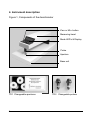
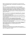
Heiland electronic GmbH
TD / TD1 / TD2
B&W-Densitometers
USERS MANUAL
Version 5
2
Table of Contents
1. GENERAL INFORMATION........................................................... 4
2. SAFETY REGULATIONS ............................................................. 5
3. AREA OF APPLICATIONS........................................................... 5
4. INSTRUMENT DESCRIPTION...................................................... 6
5. INSTALLATION ............................................................................ 9
6. READING.................................................................................... 10
7. CARE OF INSTRUMENT ............................................................ 12
8. CALIBRATION CHECK .............................................................. 12
9. GUARANTEE ............................................................................. 13
10. TECHNICAL DATA................................................................... 14
TD / TD1 / TD2 USERS MANUAL Ver.5
3
1. General information
Dear Customer,
thank you for purchasing a Heiland densitometer. In order to become
familiar with the operation of your instrument, please read these
instructions carefully and completely before your first use.
Packing
The packaging of the instrument is shock-absorbent and
should be kept for the case of further shipping.
Shipment
Use only the original packaging for transportation and shipment. First
lay the cardboard on the surface of the base unit, then place the
plastic block between measuring head and the cardboard. Finally put
the instrument inside the plastic bag.
Put the calibration strip in the users manual and the users manual on
the bottom of the shipment-box, then place the folded cardboard on
the right side and the densitometer on the left side of the
box. Put the cable into the folded cardboard .
4
2. Safety regulations
§
§
§
§
Assure that the main voltage and the frequency on the power
supply unit is the same as the one indicated on the identification
label of the power supply unit.
It is not permitted to exchange the power supply against another
one without the permission of the manufacturer.
Always keep the instrument and the power supply in a dry place
and never immerse it in any kind of liquid.
To prevent electric shock do not open, neither the densitometer
nor the power supply. There are no user serviceable parts inside.
3. Area of applications
§
§
These densitometers are designed for the transmission
measurement of films, like B&W films for photographic
applications, X-Ray films and microfilms. The reading is taken in
units of logarithmic density (log.D) Application of this instrument in
other fields is not allowed without our written permission.
The following applications are given as a brief introduction how to
get benefits of density measurement.
- Finding the right combination of film and developer.
- Determination of true film sensitivity.
- Determination of contrast.
- Comparing diazo origin and copy
TD / TD1 / TD2 USERS MANUAL Ver.5
5
4. Instrument description
Figure 1, Components of the densitometer
Zero or Min. button
Measuring head
Mode LED’s & Display
Probe
Aperture
Base unit
TD1 Changeable apertures
6
TD2 Changeable probes
§
The id-label is located on the bottom of the base unit.
§
The case of the base unit contains the transmission lamp. The
light is emitted through an opal diffuser.
§
The top of the base unit serves as a platform, on which the film
rests during measurement.
§
The measuring head is mounted to the base unit by a precise
bearing. The integrated spring pushes the measuring head in the
upper position. The head contains the sensing electronic, below
of it the probe is mounted.
§
The transmission lamp and the displays are activated when the
measuring head is lowered.
§
The 3-digit display allows a precise reading down to 0.01 log.D.
§
If the minimum sensitivity of the system is reached or if the
measuring head is depressed to fast, the display will flash ‘-888’.
§
If an error occurs during measurement, it will be displayed in the
following way: E XX where XX is the number of the error. The
only error that can be serviced by the user, is 'E 01' i.e. there is to
much light at the probe. This will occur if the aperture (TD1) or the
probe (TD2) is removed . In this case simply install the aperture or
the probe and measure again. In all other cases please consult
the manufacturer.
§
The LED's beside the 3-digit display show the selected
measurement mode while the measuring arm is lowered.
T: Transmission measurement
D: Density values are displayed
§
The 'MIN' switch resets the density display to value 0.00, it is only
active, while the measuring head is lowered (display is on).
All other switches have no functions, except on special versions.
TD / TD1 / TD2 USERS MANUAL Ver.5
7
TD The TD densitometer has a fixed aperture mounted inside the
none exchangeable probe. The diameter of the aperture is according
to the order.
TD 1 This instrument is equipped with a set of 4 changeable
apertures with diameters of 0,5/1/2/3mm. Smaller diameters reduce
the amount of light, thus the max. density is lowered. The aperture is
changed by pressing slightly on the edge of the aperture e.g. with
the fingernail. Please take care that the aperture directs upside while
inserting. After changing the aperture, the density display has to be
reset to 0.00 log.D.
TD 2 This instrument is equipped with changeable probes. The type
MK1 is used for silver and neutral colour films and the type MK2 for
Diazo films (UV measurement).
For exchanging the probe, grip the probe with two fingers and turn it
clock wise or in the right direction (facing it from above). After 3 turns,
it can be released.
Attention: Don't press the measuring head down without a mounted
probe. Otherwise you may damage the spring (bearing).
Place the other probe in the hole inside the base of the measuring
head and secure that the axial direction of the probe is in a right angle
to the base of the measuring head.
Turn the probe counter clock wise or in the left direction (facing it from
above). After some turns, it is fastened. Use no tools for fastening.
After changing the probe, the density display has to be
reset to 0.00 log.D.
Option 03: PC port
At the back side of the base unit is an USB connector located. A
suited cable to connect the densitometer to a PC is delivered with this
option. See appendix for details.
8
5. Installation
5.1 Location conditions.
§
Store and use this instrument only in rooms with a temperature
from 17°C to 27°C (degree Celsius) and relative humidity from 0
to 70 percent. Fast temperature variations may cause
condensation inside the densitometer. Wait at least 30 minutes
after moving the instrument from cold to warm environment
(more than 10°C temperature difference)
§
Keep the densitometer away from these environment:
- Direct Sunlight
- Instruments that emit heat
- Aggressive chemicals or liquids
- Strong magnetic fields, e.g. from transformers, voltage
stabilisers or loud speakers
- Electronic devices that emit strong interference like dimmers
5.2 Switching on.
§
Assure that the main voltage of the power supply unit is the same
as the one indicated on the identification label of this unit.
§
Connect the power supply first to the densitometer and then into
the wall plug
§
The instrument switches on automatically in a stand by mode.
Wait at least 2 minutes before taking the first reading.
TD / TD1 / TD2 USERS MANUAL Ver.5
9
6. Reading
6.1 General instructions.
§
Caution: Always depress the measuring head softly until it stops
on the film to be measured.
§
To prevent damage of the precise bearing, always let the
measuring head return slowly to the "up" position! Never try to
raise it higher than this stop position!
§
On a digital display, the actual value may intermit between two
values. The display changing back and forth between two values
should not be a cause for concern.
6.2 Instructions to avoid incorrect reading.
§
Especially when measuring high densities the subject must be
free from dust, lint, finger prints, and other contaminants.
§
Thick glass plates or filters should be read in low ambient light
because of their light conducting tendency.
§
Films should be placed on the reading area with the emulsion
side down.
6.3 Instructions for reset to zero.
§
Reset the display before starting a series of density
measurements. If the part of the subject used for zeroing does not
have the lowest density, a negative sign will appear while
measuring lower density.
§
Since in photographic applications density is measured above the
base fog, zeroing should always be done on the base fog. That is
an unexposed, but a developed area of film.
10
§
For other applications, the free light-flux can be used for zeroing,
this is equivalent to absolute-zero. If for the measurement of thick
glass plates or filters zeroing to the free light flux is required, then
the subject to be read must be placed on the surface of the filter
or glass plate, so that the light source is not covered up, but the
probe rests on the plate when the measuring head is depressed.
I.e. the probe must always have the same height, while setting the
zero density and while measuring.
6.4 Density measurement.
§
After zeroing the display, measurement is done by slightly
lowering the measuring head until light comes on, then centre the
area to be read over the light source and reading the value with
the fully depressed measuring head.
TD / TD1 / TD2 USERS MANUAL Ver.5
11
7. Care of instrument
§
The housing and especially the reading area should only be
cleaned with a lightly dampened soft cloth or chamois, if
necessary with the addition of a mild cleaner
§
Do not use solvents or abrasive materials.
§
The measuring head and probe should only be cleaned from dust
with a soft brush or compressed air.
§
Unplug the power supply when not in use for long time periods.
§
For necessary repairs send the densitometer and the power
supply unit to manufacturer or authorised service centre. Any
unauthorised opening, will invalidate your guarantee.
§
CAUTION: To prevent an electric shock do not open the power
supply! There are no user serviceable parts inside!
8. Calibration check
The instrument is calibrated at the factory. Certification is shipped
with the instrument in the form of a transmission calibration strip on
which the density values of the calibration are recorded. If the fields
are only numbered 1,2,3,4 please refer to the attached calibration
list.
Note: The densitometer and the calibration strip shipped with it
belong together. Since measuring geometry may defer, the calibration
strip should not be used to check other densitometers.
The calibration strip is made of photographic material. It should be
kept in a dark, cool, dry, and dust-free place to protect density values.
Do not touch reading area with bare hands. Soiled reading areas
cause incorrect readings, especially on high densities.
12
Checking the calibration should be done under the following
conditions:
§ Ambient temperature 20° to 22° Celsius.
§ Relative humidity between 0 and 70 %
§ Voltage and frequency must be in tolerance to the one indicated
on the identification label of the power supply.
§ The instrument should be acclimated to ambient conditions and
have been connected to the power source for a minimum of 5
minutes before calibrating.
§ Use aperture with 3mm diameter (TD1 only).
§ Position the calibration strip so, that the left field (0,00) of it is
centred over the light source. Reset the display to zero.
§ Reading of densities is done in the centre of each test area. If a
slight drifting of values is encountered, the values should be
averaged.
§ The tolerance is ±0.02 log. D. If greater variations are
encountered, the densitometer and the calibration strip should be
sent to the manufacturer or authorised service centre, since a
new calibration is not possible without the necessary testing
devices.
9. Guarantee
This instrument is fully guaranteed for the period of two years from
date of purchase. Proof of purchase is the invoice or receipt.
Damages due to improper handling or unauthorised access are
excluded.
This instrument has been carefully manufactured and tested using
defect free materials and state-of-the-art technology.
In case of a failure the instrument should be returned free of charge
to the manufacturer or authorised service centre accompanied by
proof of purchase.
For the warranted period, the manufacturer will pay cost of
replacement parts and repair. However, the manufacturer reserves
the right to exchange the instrument. Important: Both the instrument
and calibration strip must be send back together!
TD / TD1 / TD2 USERS MANUAL Ver.5
13
10. Technical data
§
§
§
Dimensions length x width x height
Weight
Voltage requirements
§
§
Power consumption
Aperture diameter
§
Reading geometry
standard
Diazo UV probe of TD2
: diffuse/directed
: directed/directed
Maximum subject size
Width x Height
: 260 mm x 2 mm
Maximum measurable density
TD and TD1 aperture
Æ3,0mm
Æ2,0mm
Æ1,0mm
Æ 0,5mm
TD2
Reading variation
Repeat accuracy
Temperature range
Relative humidity
Accessories
: 4,0 D
: 3,5 D
: 3,0 D
: 2,0 D
: 2,5 D
: ±(1% + 0,02 log.D.)
: ± 0,01 D
: 17 ... 27 °C
: 0 ... 70 %
: one calibration strip
§
§
§
§
§
§
§
14
: 200 x 100 x 100 mm
: 1 kg
: 12 V DC by use of a wall
plug power supply
: 3 VA
: 0,5/1/2/3 mm
according to the order
Appendix: Communication parameters
Appendix: Communication parameters
§
Communication port type: USB 2, emulating a serial com port with
9600 Baud, 8 Databit, 2 Stopbit.
§
The measurement value is transmitted automatically by the
instrument every time there is a stable value for about 1 second.
Following syntax is used:
Character-No. possible Char. meaning
1 T/0
Mode Transmission/StandBy
2 +/Sign
3 0...9/. Value MSB
4 0...9/. Value
5 0...9/. Value
6 0...9/. Value LSB
7 D/% Unit Density or Percentage of dot area
8 CR
End of string
§
Examples:
T+1.53D
Transmission density: +1.53 log D
0+....D Stand By
Issue date: December 2004
Technical data may change without notice.
TD / TD1 / TD2 USERS MANUAL Ver.5
15
Heiland electronic GmbH
Schulstraße 8
D-35579 Wetzlar
Telefon: ++49 6441 26978
Fax:
++49 6441 26988
email:
Internet:
[email protected]
http://www.heilandelectronic.de