1
ACUMEN INSTRUMENTS CORPORATION
DataBridge SDR
User’s Manual
revision 1.2 • 2/99
Copyright
This document is copyrighted by Acumen Instruments Corporation with all rights reserved.
No part of this document may be reproduced in any form without prior written consent of
Acumen Instruments Corporation.
Copyright © 1998-1999 by Acumen Instruments Corporation. All rights reserved.
Disclaimer
This manual has been thoroughly reviewed for accuracy, and every effort has been made to
ensure that the information is accurate and complete. However, different versions of this
product have different features and capabilities, and this manual only reflects one of those
versions. Therefore, Acumen Instruments Corporation assumes no responsibility for errors,
omissions or defects in this material, and shall not be liable for any damages resulting from
their use.
The information in this document is subject to change without notice.
ACUMEN INSTRUMENTS CORPORATION MAKES NO WARRANTY OF ANY KIND WITH RESPECT TO
THIS DOCUMENT, EITHER EXPRESSED OR IMPLIED, INCLUDING WITHOUT LIMITATION ANY
IMPLIED WARRANTIES OF MERCHANTABILITY OR FITNESS FOR A PARTICULAR PURPOSE.
Table Of Contents
Getting Started ....................................................................... 1
1.1
1.2
1.3
1.4
1.4.1
Overview.................................................................................................1
Before you start ......................................................................................2
A quick guide to DataBridge SDR ..........................................................2
Deploying DataBridge SDR ....................................................................3
Connecting the power supply and serial cables to your data
recorder ............................................................................................3
Locating your computer’s serial port....................................................4
1.4.2 Communications software ......................................................................5
Configuring DataBridge SDR .................................................. 7
2.1
2.2
2.3
2.4
2.5
2.6
Setting date and time..............................................................................8
Setting data port baud rate .....................................................................9
Data port handshaking ...........................................................................9
Specifying a filename .............................................................................9
Notes about filenames.......................................................................10
Entering messages...............................................................................10
Setting message parameters.............................................................11
Testing your configuration ....................................................................12
Operating DataBridge SDR .................................................. 13
3.1
3.2
3.2.1
3.2.2
3.2.3
3.2.4
3.2.5
3.2.6
3.3
3.4
Stop mode ............................................................................................13
Record mode ........................................................................................13
Receiving data......................................................................................14
Power failure and improper shutdowns ................................................14
Full storage media ................................................................................14
Formatting the storage media...............................................................14
Partitions...............................................................................................14
Considerations for slow devices ...........................................................15
Play mode.............................................................................................16
Real-time clock considerations.............................................................16
Configuration Menu Reference............................................. 17
4.1
4.2
4.3
4.4
Main Menu ............................................................................................17
Edit Messages ......................................................................................19
SCSI Drive Functions ...........................................................................19
File System Functions ..........................................................................21
DIP Switch Reference........................................................... 25
5.1
5.1.1
5.1.2
5.1.3
5.1.4
5.1.5
5.1.6
5.1.7
5.1.8
5.1.9
Overview...............................................................................................25
Enabling data port handshaking (switch 1)...........................................26
Enabling configuration port handshaking (switch 2) .............................26
Reserved switches (switches 3 and 4) .................................................26
Displaying and hiding menus (switch 5) ...............................................26
Disabling buttons (switch 6)..................................................................26
Disabling indicators (switch 7) ..............................................................26
Disabling resume mode (switch 8) .......................................................26
Initiator ID (switch 9).............................................................................27
Setting configuration port baud rate (switches 10-12) ..........................27
i
Table Of Contents
DataBridge SDR User’
s Manual rev 1.2
Troubleshooting ....................................................................29
6.1
Frequently Asked Questions (FAQ) ..................................................... 29
Service and Support .............................................................33
7.1
7.1.1
7.1.2
7.1.3
7.1.4
7.2
7.3
7.3.1
7.3.2
7.3.3
Contacting Acumen Instruments Corporation ...................................... 33
Technical support................................................................................. 33
Mail 33
E-mail ................................................................................................... 34
World Wide Web.................................................................................. 34
Returning Equipment ........................................................................... 34
Warranty............................................................................................... 34
One year warranty................................................................................ 34
Exclusions ............................................................................................ 34
Limitations ............................................................................................ 35
DataBridge SDR Evaluation Kit.............................................37
A.1
A.2
A.2.1
A.3
Overview .............................................................................................. 37
Front panel ........................................................................................... 38
Accessing DIP switches and RTC battery............................................ 38
Rear panel............................................................................................ 39
Serial Port Basics..................................................................41
B.1
B.2
B.2.1
B.3
B.3.1
B.3.2
B.3.3
Serial specifications ............................................................................. 41
Data rates............................................................................................. 41
Data rates and the UART ..................................................................... 42
More asynchronous serial parameters ................................................. 43
DTE and DCE....................................................................................... 43
Handshaking ........................................................................................ 44
Voltage levels....................................................................................... 45
DataBridge SDR Electrical Specifications.............................47
C.1
C.1.1
C.2
C.3
Power requirements ............................................................................. 47
Power receptacle pin configuration ...................................................... 48
Serial communications ......................................................................... 48
SCSI interface ...................................................................................... 48
DataBridge SDR Mechanical Specifications .........................49
D.1
Dimensions .......................................................................................... 49
D.2
Environment ......................................................................................... 50
D.2.1 Desiccant ............................................................................................. 50
ii
DataBridge SDR User’
s Manual rev 1.2
Table Of Contents
The Switch Closure Interface................................................ 51
E.1
E.2
E.3
E.4
E.5
E.6
E.6.1
E.6.2
E.6.3
E.7
E.7.1
E.7.2
E.7.3
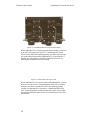
Description............................................................................................51
Operation..............................................................................................51
Switch Closure Interface Data Format..................................................54
Schematic.............................................................................................55
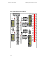
PCB Component Locations ..................................................................56
Bill of Materials .....................................................................................57
Switch Closure Interface: Circuit Board................................................57
Switch Closure Interface: Internal Cable Assemblies...........................57
Switch Closure Interface: External Cable Assemblies..........................58
Specifications .......................................................................................58
Power Requirements ............................................................................58
Isolation ................................................................................................59
Switch sampling rate ............................................................................59
iii
1
Getting Started
1.1
Overview
The DataBridge Serial Data Recorder (SDR) is designed to record serial
data to a SCSI mass storage device using a MD-DOS™/Windows™compatible FAT file. An intuitive three-button user interface activates
DataBridge SDR’
s Stop, Play and Record modes.
DataBridge SDR is equipped with two serial ports. With terminal software
on a PC, you can use the configuration port to manage files, configure and
communicate with the data port, set date and time, set up output messages,
download data, configure the storage media, and enter Record and Play
modes. During Record mode, you can also monitor recording using the
configuration port.
During Record mode, the data port accepts RS-232C serial data from your
data source. For data sources that require initialization or querying,
DataBridge SDR can store and transmit up to ten user-defined messages.
Each message is independent and can be sent once at power-up or
periodically at specific intervals.
The data source is a
device that transmits
serial data for use by a
computer, printer, or
data logger.
DataBridge SDR’
s ports support baud rates up to 230,400 bps and hardware
handshaking for reliable high-speed communication. DataBridge SDR is
also equipped with a real-time clock, power-saving features, non-volatile
memory, and resume-on-power failure feature.
1
Getting Started
1.2
DataBridge SDR User’
s Manual rev 1.2
Before you start
Before you start, be sure you have the following items available:
• The DataBridge serial data recorder (SDR)
• A power supply
• The DataBridge SDR dual serial cable
• The manual supplied with your computer or terminal
1.3
A quick guide to DataBridge SDR
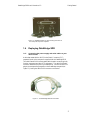
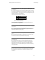
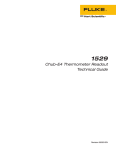
DataBridge SDR’
s basic functions are controlled using the three buttons
located on the front panel (see Figure 1.1). The indicators in the buttons
indicate the DataBridge SDR’
s current operating mode (Stop, Play, Record).
The data indicator indicates that data is received by DataBridge SDR and is
used to verify proper function of the data recorder.
Figure 1.1. DataBridge SDR's front panel showing the location of
the data indicator and Play, Stop, and Record buttons.
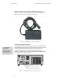
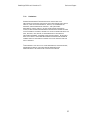
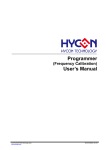
The power connector (see Figure 1.2) found on DataBridge SDR’
s back
panel supplies 5 VDC and/or 12 VDC. The serial connector connects
DataBridge SDR to your data source and (optionally) a PC running
communications software. The SCSI connector is used for high-speed data
downloads using a PC equipped with a SCSI adapter.
2
DataBridge SDR User’
s Manual rev 1.2
Getting Started
Figure 1.2. DataBridge SDR's rear panel showing the location of
the serial ports and power receptacle.
1.4
Deploying DataBridge SDR
1.4.1
Connecting the power supply and serial cables to your
data recorder
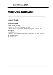
A cable that mates with the AMP Circular Plastic Connector (CPC)
receptacle found on the rear panel is supplied with the DataBridge SDR.
The cable’
s female DB9 connector mates with the male connector typically
found on computers (and other DTE equipment). The cable’
s DB9 male
connector mates with the port on your data source. Connect the AMP CPC
plug to the corresponding receptacle on the DataBridge rear panel (see
Figure 1.2), leaving the cable’
s DB9 connectors unconnected.
Figure 1.3. The DataBridge SDR dual serial cable.
3
Getting Started
DataBridge SDR User’
s Manual rev 1.2
Similarly, the power supply included with DataBridge SDR uses a 4-pin
AMP CPC connector. Connect the power supply to DataBridge SDR, but
leave the IEC cable (for 120 VAC power) unconnected.
Figure 1.4. A DataBridge SDR 120VAC power supply.
Locating your computer’s serial port
Your computer’
s
female DB25
connector is most
likely a parallel port,
not a serial port.
Your serial port is found on the back of your computer. Most computers are
equipped with either a DB9 or DB25 male connector (see Figure 1.5). Male
connectors have pins, while female connectors have sockets. If your
computer uses a serial mouse, it may already occupy your DB9 male
connector. Likewise, if your computer is equipped with an external modem,
it may occupy your DB25 male connector.
DB9 male connector
DB25 male connector
Figure 1.5. Locating the serial port on the rear panel of a PC.
4
DataBridge SDR User’
s Manual rev 1.2
Getting Started
If you are unable to locate your serial port(s), consult the documentation
included with your computer. If all of your computer’
s serial port(s) are
occupied, contact your manufacturer or support provider for information
about adding a serial port to your computer.
If your computer is equipped with a DB9 male receptacle, connect the
DataBridge SDR dual serial cable’
s DB9 female connector to your
computer. If your computer’
s available serial port is a DB25 male
connector, you will need to purchase a DB9M to DB25F adapter, often
referred to as an AT adapter, to connect the 9-pin DataBridge SDR cable to
your 25-pin serial port (the adapter has DB9 male and DB25 female
connectors).
Figure 1.6. DB25 female to DB9 male adapters (AT adapter).
Once you have located your serial port, you need to know whether your port
is configured for operation as COM1, COM2, COM3, or COM4 (some
computers even include COM5-COM8). In most cases, a port that uses a
DB9 male connector is configured as COM1 (or perhaps COM3), while a
DB25 male connector is configured as COM2 (or COM4). If some of your
computer’
s ports are occupied by a mouse, modem, serial printer, or other
serial device, you may need to explore your computer’
s configuration
information and use a process of elimination to determine your port’
s COM
designation.
1.4.2
Communications software
Now that DataBridge SDR is connected to your computer, you must
configure communications software (also known as terminal software) to
communicate with it. Typical communications software includes: Procomm
Plus™, Crosstalk™, and Telix™ (available for DOS users), Windows
Terminal (included with Microsoft® Windows™ 3.1 and Windows NT
3.51), and HyperTerminal™ (included with Microsoft Windows 95/98/NT
4.0).
Configure your software to communicate using the serial port you connected
to DataBridge SDR, the appropriate baud rate (probably 9600 bps), and the
serial data format parameters (probably 8N1). See Section 0 if you need to
5
Getting Started
DataBridge SDR User’
s Manual rev 1.2
change DataBridge SDR’
s serial parameters to match your communications
software.
Be sure your software is configured for half-duplex mode (local echo is off)
and that your software isn’
t adding line feeds to incoming carriage returns.
If your software supports it, enable ANSI or VT-100/VT-102 terminal
emulation.
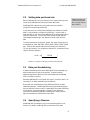
Once DataBridge SDR is connected to your computer and you are running
terminal software, apply power by connecting the power supply’
s IEC cable
to 120 VAC power. The DataBridge main menu should appear (see Figure
1.7).
Acumen Instruments Corporation
DataBridge SDR firmware rev. 1.2b
1
2
3
4
Set time
Set date
Toggle ANSI mode (ANSI is ON)
Toggle messages (messages are OFF)
5
6
7
Edit messages...
SCSI drive functions...
File system functions...
8
9
Enter serial passthrough mode
Set baud rate for attached device
P
R
Enter PLAY mode
Enter RECORD mode
12/02/1998 14:20:30
Current filename is: BRIDGE01.DAT
Enter choice (1,2,3,4,5,6,7,8,9,P,R)
Figure 1.7. The DataBridge main menu.
6
2
Configuring
DataBridge
SDR
Now that you have access to DataBridge SDR’
s menu system, you are ready
to configure it for use with your serial data source. To accomplish this you
must:
• Set DataBridge SDR’
s date and time.
• Specify a filename for recording.
• Ensure that the media you are using is properly formatted and has
enough free space to accommodate your data.
• Be sure that DataBridge SDR and your device are communicating at the
same speed and with the same serial data format parameters.
• Determine whether you need to use hardware handshaking to
communicate with your device.
• Connect your device to DataBridge SDR.
• Check to see that your data source can communicate with DataBridge
SDR.
Before you begin, be sure you have the documentation available for your
serial data source. If possible, be sure you can communicate with the data
source using the supplied software and/or your communications software.
This intimate knowledge of your data source's communications standards
will make connecting it to DataBridge SDR simple.
7
Configuring DataBridge SDR
2.1
For more information
about DataBridge
SDR menus, see
chapter 4.
DataBridge SDR User’
s Manual rev 1.2
Setting date and time
DataBridge SDR features a real-time clock that reports the last modified
date and time in a directory entry. The real-time clock is preset and batterybacked, so setting the date and time is seldom necessary.
To set the time, press 1 at the menu prompt. Then, when prompted further,
enter the time in 24-hour format using two digits for each of hours, minutes,
and seconds (omit the colons (:) between each field). Press any key to
return to the DataBridge main menu. For an example, see Figure 2.1.
Acumen Instruments Corporation
DataBridge SDR firmware rev. 1.2b
1
2
3
4
Set time
Set date
Toggle ANSI mode (ANSI is ON)
Toggle messages (messages are OFF)
5
6
7
Edit messages...
SCSI drive functions...
File system functions...
8
9
Enter serial passthrough mode
Set baud rate for attached device
P
R
Enter PLAY mode
Enter RECORD mode
12/02/1998 14:42:14
Current filename is: BRIDGE01.DAT
Enter choice (1,2,3,4,5,6,7,8,9,P,R) 1
Current time is 14:42:15
Enter new time (hh:mm:ss) 09:00:00
Time set to 09:00:00
Press any key to continue...
Figure 2.1. Setting the time.
To set the date, press 2 at the menu prompt. Then, enter the date using two
digits for each of the month, day, and year fields (omitting any hyphens or
other characters). Press any key to return to the DataBridge main menu.
See Figure 2.2 for an example.
Acumen Instruments Corporation
DataBridge SDR firmware rev. 1.2b
1
2
3
4
Set time
Set date
Toggle ANSI mode (ANSI is ON)
Toggle messages (messages are OFF)
5
6
7
Edit messages...
SCSI drive functions...
File system functions...
8
9
Enter serial passthrough mode
Set baud rate for attached device
P
R
Enter PLAY mode
Enter RECORD mode
02/05/1998 14:42:14
Current filename is: BRIDGE01.DAT
Enter choice (1,2,3,4,5,6,7,8,9,P,R) 2
Current date is 02/05/98
Enter new date (mm/dd/yy) 02/04/98
Date set to 02/04/98
Press any key to continue...
Figure 2.2. Setting the date.
8
DataBridge SDR User’
s Manual rev 1.2
2.2
Configuring DataBridge SDR
Setting data port baud rate
DataBridge SDR uses
a format of eight data
bits, no parity, and one
stop bit (8N1).
Before DataBridge SDR and your data source can communicate, they must
interact at the same data rate and using the same data format.
DataBridge SDR's data port and configuration port are, by default,
configured to communicate at 9600 bps.
If your data source can communicate at 9600 bps (also referred to as 9600
baud), it may be easiest to configure it for 9600 bps. For devices with a
fixed data rate, you will need to set DataBridge SDR's data port baud rate to
match your data source. You may also wish to choose a higher data rate
(and hardware handshaking) if your data source sends a high volume of
data.
To set the baud rate for the data port, press 9, then select a baud rate from
the displayed list (2400, 4800, 9600, 19200, 38400, 57600, 115200, 230400
bps). Select a baud rate that matches the rate used by your data source.
You can use Equation 2.1 to configure the data port for “nonstandard”baud
rates like 7200 and 3600 bps.
7372750
divisor = int
desired baud rate in bps
Equation 2.1. Equation for specifying an arbitrary baud rate divisor.
2.3
Data port handshaking
Hardware handshaking ensures that DataBridge SDR sends messages only
when the data source is ready to accept them. Likewise, hardware
handshaking prevents a data source from sending data when DataBridge
SDR is not ready to receive it.
Remove DataBridge SDR’
s front panel (see Figure 5.1) and turn switch 1 on
(see Table 5.1) to enable handshaking on the data port.
Be sure that your serial data source and DataBridge SDR use the same
handshaking settings. If DataBridge SDR monitors the handshaking signal
but your data source does not send it, DataBridge SDR may wait indefinitely
for "permission" to transmit messages. Likewise, if your data source
monitors the handshaking signals but DataBridge SDR doesn't send the
signal, the software may never transmit output data.
2.4
Specifying a filename
DataBridge SDR records data to a file in the mass storage device’
s root
directory. By default, DataBridge SDR records data to a file called
9
Configuring DataBridge SDR
DataBridge SDR User’
s Manual rev 1.2
BRIDGE.DAT. You can keep this filename or specify a new filename that
DataBridge SDR
records and plays only
files found in the root
directory of the disk.
reflects the data it contains. For example, you may wish to use
PRESSURE.TXT for pressure data or even a name like TEMP0998.TXT for
temperature data from September 1998.
Notes about filenames
When you enter filenames, they must conform to the DOS 8+3 filename
format. This means that files contain up to 8 characters, a period ("dot"),
and up to three more characters. For example, BRIDGE.DAT,
ABCDEFGH.123, and 1 are all valid filenames, while DATA.FILE, and
JOHNSMITH.TXT are not. DataBridge SDR ignores characters you type that
are not allowed in DOS filenames, such as: \/*|[].
To specify the name of the file DataBridge will use for recording data, press
7 at the main menu prompt to enter the File System Functions submenu
(see Figure 2.3).
From the File System Functions menu, press 2. Then, when prompted, type
a filename, pressing the Enter key when finished if your file extension is
shorter than three characters. If your filename (without extension) is eight
characters, DataBridge automatically enters the period (“dot”) before the
extension. You can return to the main menu by pressing Q.
Acumen Instruments Corporation
DataBridge SDR firmware rev. 1.2b
1
2
3
4
5
6
7
8
Q
Current filename is: BRIDGE01.DAT
Display root directory
Change current filename
Delete file
Rename file
Toggle append mode (append is ON)
Download file via XMODEM
Download file as ASCII text
Set scheduled file close parameters (OFF)
Return to main menu
Enter choice (1,2,3,4,5,6,Q) 2
Enter new filename (<cr> to end): ABCDEFGH.123
Figure 2.3. Specifying a filename.
2.5
Entering messages
Some data sources need to receive specific data strings or commands before
they will transmit data. Other data sources send data continuously once they
are initialized with a specific string or command. If your device transmits
data continuously without requiring input, you don’
t need to send output
messages.
10
DataBridge SDR User’
s Manual rev 1.2
Configuring DataBridge SDR
You can configure DataBridge SDR to send up to ten independent messages
to the data source on startup, periodically, or both, on intervals from
once/second to once/194 days.
Messages are stored as ASCII text strings in non-volatile memory. These
storage locations are referred to as messages 0-9. To use messages, first
enter a text string as one of the ten messages. Next, configure the message
to be sent on initialization or at an interval specified in seconds. DataBridge
SDR can also be configured to append a carriage return <CR> and/or line
feed <LF> to any message.
To enter a new message, press 5 at the main menu prompt to enter the Edit
Messages submenu. Then, press 1 to edit a message. When prompted,
enter the desired message number (0-9) and type a message followed by the
Enter key.
Acumen Instruments Corporation
DataBridge SDR firmware rev. 1.2b
#
0
1
2
3
4
5
6
7
8
9
interval
00000000
00000000
00000000
00000000
00000000
00000000
00000000
00000000
00000000
00000000
1
2
Q
I
N
N
N
N
N
N
N
N
N
N
CR
N
N
N
N
N
N
N
N
N
N
LF message contents
N
N
N
N
N
N
N
N
N
N
Edit message contents
Edit message parameters
Return to main menu
Enter choice (1,2,Q) 1
Enter message number (0-9): 0
Enter message(<cr> to end): ASTRAL
Figure 2.4. Changing message zero to “ASTRAL”.
Setting message parameters
To change a message’
s parameters, press 2 at the menu prompt. When
prompted, enter the desired message number (0-9) and type a message
followed by the Enter key.
Output intervals: DataBridge sends a message, then waits a specific amount
of time before sending the message again. DataBridge prompts you to enter
this waiting period, or output interval. To disable a message (but leave its
contents intact), enter 0. For instance, if the message should be output once
every ten seconds, enter 10 and press the Enter key.
Initialization: Some devices begin sending data only after receiving a specific
command, the initialization string. When prompted, press Y to indicate that
DataBridge SDR should send the message once when it enters Record
mode. This feature can be used together with output interval to both
initialize a device with a specific message and send the message periodically.
This is useful for resetting a data source periodically or automatically
11
Configuring DataBridge SDR
DataBridge SDR User’
s Manual rev 1.2
reinitializing a data source if its power is lost. Entering N disables this
feature.
Carriage return and line feed: When prompted, enter Y when prompted to
instruct DataBridge SDR to add a carriage return and/or line feed to the end
of a message. Many devices require a carriage return and/or line feed after a
message, while others require neither. Entering N disables this feature.
Your data source’
s documentation can help you determine whether carriage
returns and/or line feeds are required.
Acumen Instruments Corporation
DataBridge SDR firmware rev. 1.2b
#
0
1
2
3
4
5
6
7
8
9
interval
00000000
00000000
00000000
00000000
00000000
00000000
00000000
00000000
00000000
00000000
1
2
Q
I
N
N
N
N
N
N
N
N
N
N
CR
N
N
N
N
N
N
N
N
N
N
LF message contents
N
N
N
N
N
N
N
N
N
N
Edit message contents
Edit message parameters
Return to main menu
Enter choice (1,2,Q) 4
Enter message number (0-9): 0
Enter output interval in seconds (0-16777215): 10
Initialize with this message (Y/N)? N
Append carriage return to this message (Y/N)? Y
Append line feed to this message (Y/N)? Y
Figure 2.5. Configuring message zero.
2.6
Messages with only a
carriage return (no line
feed) after them will
appear to overwrite
previous messages in
your terminal software.
You can enable your
communications
software’
s "append
linefeeds to incoming
carriage returns"
feature to see these
messages properly.
Testing your configuration
To test your configuration, you can disconnect the configuration port plug
and use a null modem adapter or cable to connect the dual serial cable's
male DB-9 plug to the computer running communications software. Your
computer then becomes a data source.
Press the Record button on the front panel. After a few seconds,
DataBridge SDR’
s record indicator will light and the output messages you
entered will be displayed at the specified output interval.
To ensure that recording is occurring, type several keystrokes on the
computer running communications software or use the software’
s ASCII
upload feature to send a text file. DataBridge SDR’
s data indicator should
blink as you press keys. When finished, press the Stop button on the front
panel. Then, press the Play button to view the data you typed or uploaded.
Note: DataBridge SDR will not display data while it is being recorded. You
can enable your terminal software’
s "local echo" or "full duplex" feature to
view data as you send it.
12
3
Operating
DataBridge
SDR
3.1
Stop mode
Stop mode is the default power up mode. When DataBridge SDR is in Stop
mode, the Stop indicator is illuminated and you can access menu functions
using communications software on a computer attached to the configuration
port.
Before you connect your device, be sure DataBridge SDR is in Stop mode.
3.2
Record mode
When you press the Record button or type R from the main menu,
DataBridge SDR searches for the file you specified in the File System
Functions menu, creates it if necessary, and opens it. Once DataBridge
SDR has successfully opened the file, the record indicator glows and
DataBridge SDR enters Record mode.
Once in Record mode, DataBridge SDR transmits the messages stored in
nonvolatile memory at the specified intervals to the data source connected to
its data port.
13
Operating DataBridge SDR
3.2.1
DataBridge SDR User’
s Manual rev 1.2
Receiving data
Incoming data is appended to the open file as it is received until you press
the Stop button. DataBridge SDR then closes the file, updates its directory
entry (recording file size, date, and time), and returns to Stop mode.
The data indicator, found on DataBridge SDR’
s front panel (see Figure 1.1),
flashes when the data source transmits data. This indicator is useful to
ensure that DataBridge SDR is actually receiving data via the data port.
3.2.2
Power failure and improper shutdowns
If DataBridge SDR loses power while in Record mode, it returns to Record
mode after power is restored. For troubleshooting, this feature is disabled by
setting switch 8 to the on position (see Table 5.1).
An improper shutdown may result in loss of data (due to sector buffering
and caching in the storage device) and minor allocation errors that can be
repaired using the MS-DOS™ SCANDISK.EXE utility, Norton Disk
Doctor™, or Windows 95/98/NT™ Explorer.
3.2.3
Full storage media
When the storage media’
s first valid partition is full, DataBridge SDR
returns to Stop Mode.
DataBridge SDR ejects the disk if you are using removable media. You can
delete files on the target media using your computer or replace it, then insert
the media and press the record button and append data normally.
3.2.4
If your storage media
was included with
DataBridge SDR, it is
already formatted
properly. Most
preformatted media
(such as Zip and Jaz
disks) is also ready for
use.
Formatting the storage media
If you have purchased media for use with a removable mass storage device
or you are installing a new storage device, you will need to format it using
MS-DOS™, Windows 95/98™, Windows NT™, or another operating system
that supports the FAT file system.
DataBridge SDR supports only the FAT file system. If your computer
supports the NTFS, FAT32, HPFS, or other advanced file systems, be sure
your disk is formatted using conventional FAT.
3.2.5
Partitions
In some cases, disks are partitioned to contain multiple "virtual" drives on a
single disk. Partitioning is often done to overcome the 2 gigabyte size limit
in MS-DOS™ (and create multiple 2 gigabyte drives), support multiple
operating systems and file systems, or make more efficient use of disk space
(by using a smaller cluster size).
14
DataBridge SDR User’
s Manual rev 1.2
Operating DataBridge SDR
FDISK.EXE (included with MS-DOS™ and Windows 95/98™), Disk
Administrator (included with Windows NT™), Norton Disk Doctor™, and
Norton DiskEdit™ are useful tools for managing and analyzing disk
partitioning schemes.
DataBridge SDR supports both extended and primary FAT and VFAT
partitions, but always reads and writes files in the first partition it recognizes
as FAT or VFAT.
3.2.6
Considerations for slow devices
Mass storage devices, particularly low-power and removable devices,
sometimes suffer from slow disk access times. It is important to note that
access times quoted by manufacturers are averages. A worst-case access
time can be ten times the number specified. For instance, a drive with a 25
millisecond average access time may sometimes require 250 milliseconds or
more to access a sector.
DataBridge SDR includes a 224-byte character buffer to store characters
received during slow disk accesses. The maximum disk access time before
DataBridge SDR asserts its handshaking signalor characters are lost can be
calculated using Equation 3.1.
t max ≅
224 bytes
average byte rate
Equation 3.1. Maximum disk access time.
The average byte rate for a serial data source that transmits data
continuously given in Equation 3.2.
average byte rate =
bits
1 byte
×
second 10 bits
Equation 3.2. Average byte rate.
So, if a data source transmits data continuously at 9600 bps, the maximum
disk access time is approximately 240 ms.
Most data sources transfer data in short bursts. For example, a device may
send a 10-byte message once per second. In this case, the average byte rate
is simply 10 bytes/second and the maximum disk access time becomes 22.4
seconds.
If your maximum disk access time exceeds your media’
s worst-case access
time, you can expect occasional data loss.
15
Enable hardware
handshaking on
DataBridge SDR and
your serial data source
when possible to avoid
data loss when using
slow media.
Operating DataBridge SDR
3.3
DataBridge SDR User’
s Manual rev 1.2
Play mode
When you press the play button (while in Stop mode), DataBridge SDR
attempts to find the specified file and open it. If it exists, DataBridge SDR
enters Play mode and transmits data via the serial port for viewing,
downloading using your communications software’
s ASCII download
feature, or even simulating the serial device for use with its software. For
example, you could record position data from a GPS receiver using
DataBridge SDR, then use Play mode to plot the data with GPS-ready
mapping software as if the receiver were connected to the computer.
Playback continues until DataBridge SDR reaches the end of the current file
or you press the stop button. You can also hold the Ctrl key and press C
(Ctrl-C) to stop data playback. Once DataBridge SDR reaches the end of
the file, you must press the stop button to return to Stop mode. This gives
you the opportunity to stop your ASCII download and/or save your data
before the menu is displayed.
3.4
Real-time clock considerations
The real-time clock DataBridge SDR uses a small lithium battery to maintain
time when power is not applied. The life of this battery should exceed 5
years.
If you find DataBridge SDR is not keeping time correctly or that the time is
displayed with a question mark (?) after it, you may need to replace the
battery.
To replace the real-time clock’
s battery, find the battery clip located next to
the DataBridge SDR DIP switches (see Figure 5.1). Pull the DataBridge
SDR circuit board forward until you can extract the battery from its holder.
Replace the battery with a Panasonic CR2032, or equivalent, making sure
the positive (+) face is in contact with the battery clip.
16
4
Configuration
Menu
Reference
The DataBridge SDR configuration menu system is split into submenus.
You can use menu functions to manage files, configure and communicate
with the data port, set date and time, set up output messages, download
data, configure the storage media, and control DataBridge SDR without
using the front panel buttons.
4.1
Main Menu
DataBridge SDR’
s core functions are accessed from the main menu (see
Figure 4.1).
17
Configuration Menu Reference
Acumen Instruments Corporation
DataBridge SDR firmware rev. 1.2b
1
2
3
4
Set time
Set date
Toggle ANSI mode (ANSI is ON)
Toggle messages (messages are OFF)
5
6
7
Edit messages...
SCSI drive functions...
File system functions...
8
9
Enter serial passthrough mode
Set baud rate for attached device
P
R
Enter PLAY mode
Enter RECORD mode
DataBridge SDR User’
s Manual rev 1.2
12/02/1998 14:20:30
Current filename is: BRIDGE01.DAT
Enter choice (1,2,3,4,5,6,7,8,9,P,R)
Figure 4.1. DataBridge SDR main menu
The main menu includes functions for controlling both DataBridge SDR and
the attached device.
Serial passthrough mode provides a means for communicating with the
device connected to the data port. To enter passthrough mode, press 8 from
the main menu. To return to the main menu, type +++, then wait two
seconds for the menu to appear.
Note: incorrect handshaking settings may cause DataBridge SDR to hang
during passthrough mode. Particularly, enabling RTS/CTS handshaking for
a device that doesn’
t support hardware handshaking may cause these hangs.
If DataBridge SDR hangs during passthrough, remove power for five
seconds, then reapplying power.
To set the baud rate for the data port, press 9, then select a baud rate from
the displayed list (2400, 4800, 9600, 19200, 38400, 57600, 115200, 230400
bps). Select a baud rate that matches the rate used by the device attached to
the data port. You can use Equation 4.1 to configure the data port for
“nonstandard”baud rates.
7372750
divisor = int
desired baud rate in bps
Equation 4.1. Equation for specifying an arbitrary baud rate divisor.
Like the Play and Record buttons, the main menu commands P and R are
used to immediately enter play and record modes. To return to stop mode,
hold the Ctrl key and press C (Ctrl-C) or press the Stop button.
18
DataBridge SDR User’
s Manual rev 1.2
4.2
Configuration Menu Reference
Edit Messages
To enter the Edit Messages submenu, press 5 from the main menu. The
Edit Messages menu appears (see Figure 4.2).
Acumen Instruments Corporation
DataBridge SDR firmware rev. 1.2b
#
0
1
2
3
4
5
6
7
8
9
interval
00000000
00000000
00000000
00000000
00000000
00000000
00000000
00000000
00000000
00000000
1
2
Q
I
N
N
N
N
N
N
N
N
N
N
CR
N
N
N
N
N
N
N
N
N
N
LF message contents
N
N
N
N
N
N
N
N
N
N
Edit message contents
Edit message parameters
Return to main menu
Enter choice (1,2,Q)
Figure 4.2. The Edit Messages submenu.
The items in the Edit Messages submenu perform like menu items 3 and 4
of the menu described in the User’
s Manual.
From the main menu (see Figure 4.1), pressing 4 enables or disables all
messages. If you are using the message feature, be sure the main menu
displays “messages are ON”after menu item 4.
To return to the Main menu from the Edit Messages menu, press Q.
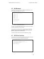
4.3
SCSI Drive Functions
To enter the SCSI Drive Functions submenu, press 6 from the Main menu.
The SCSI Drive Functions menu appears (see Figure 4.3).
Acumen Instruments Corporation
DataBridge SDR firmware rev. 1.2b
1
2
3
4
5
Q
Select SCSI target ID (ID=05)
Set power-on delay (delay=00000015 seconds)
Set suspend parameters for Quantum hard drives (OFF)
Perform REQUEST SENSE command
Perform MODE SENSE command
Return to main menu
Enter choice (1,2,3,4,5,Q)
Figure 4.3. The SCSI Drive Functions submenu.
19
Configuration Menu Reference
DataBridge SDR User’
s Manual rev 1.2
The items in the SCSI Drive Functions menu are used primarily for
configuring DataBridge SDR with a new mass storage device or performing
diagnostics on a SCSI device. The submenu also includes spinup delay
parameters and functions specifically for Quantum hard drives.
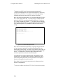
When you install a new storage device, you must tell DataBridge SDR which
SCSI ID the storage device uses. Do this by pressing 1. DataBridge SDR
prints a list of SCSI ID’
s and devices found (see Figure 4.4). The current
SCSI target is marked with the letter "T". The initiator device (DataBridge
SDR) is marked with the letter "I". Type the number (0-7) that corresponds
to the mass storage device or press Enter to keep the current target ID
setting.
target ID=0:<device timeout>
target ID=1:<device timeout>
target ID=2:<device timeout>
target ID=3:<device timeout>
target ID=4:<device timeout>
T target ID=5:IOMEGA ZIP 100
I target ID=6:DataBridge SDR firmware rev. 1.2b
target ID=7:<device timeout>
Enter desired target ID:
Figure 4.4. The select SCSI target ID function.
Menu item 2 controls drive spinup delays. The spinup delay is the amount
of time after power is applied (in seconds) that DataBridge SDR waits
before entering record mode. For instance, if the power-on delay is set to 30
seconds, DataBridge SDR will wait 30 seconds before accessing the storage
device. This allows time for drives with high spindle speeds to reach
maximum speed before reads and writes are attempted.
Use menu item 3 to configure hard drive power-saving features. When
enabled ("ON"), this feature instructs Quantum hard drives to enter a
power-saving mode (sleep mode) once they have been idle for a specific
period of time (specified in tenths of seconds).
Menu items 4 and 5 are used by support personnel to diagnose problems
with SCSI storage devices.
To return to the Main menu from the SCSI Drive Functions menu, press Q.
20
DataBridge SDR User’
s Manual rev 1.2
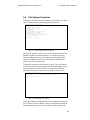
4.4
Configuration Menu Reference
File System Functions
To enter the File System Functions submenu, press 7 from the main menu.
The File System Functions submenu appears (see Figure 4.5).
Acumen Instruments Corporation
DataBridge SDR firmware rev. 1.2b
1
2
3
4
5
6
7
8
Q
Current filename is: BRIDGE01.DAT
Display root directory
Change current filename
Delete file
Rename file
Toggle append mode (append is ON)
Download file via XMODEM
Download file as ASCII text
Set scheduled file close parameters (OFF)
Return to main menu
Enter choice (1,2,3,4,5,6,Q)
Figure 4.5. The File System Functions submenu.
Using the File System Functions menu, you can display a directory of files,
delete and rename files, and download files. You can also control the
filename DataBridge SDR uses for recording, the way DataBridge SDR
resumes recording when power is lost and how often DataBridge SDR
creates a new file for recording data.
To display the current drive’
s root directory, press 1. If the root directory
contains files, each file’
s name, attributes, last modified time/date, and file
size in bytes are shown (see Figure 4.6). Once the directory has been
displayed, press any key to return to the File System Functions menu.
Enter choice (1,2,3,4,5,6,Q) 1
BRIDGE01.DAT
a
12:07:34
BRIDGE02.DAT
a
17:03:46
12/07/1998
09/15/1998
0000039424
0000115215
Press any key to continue...
Figure 4.6. Displaying the root directory.
To change the filename DataBridge SDR uses to record data, press 2 from
the File System Functions submenu. When you are finished, the specified
file name appears at the top of the File System Functions submenu (see
21
Configuration Menu Reference
DataBridge SDR User’
s Manual rev 1.2
Figure 4.5). In addition to file recording and playback, this filename is used
in menu options 3, 4, 6, and 7.
To delete a file found in the root directory, first specify the filename to
delete using menu option 2, then use menu option 3 to delete the file.
To rename a file, specify its filename using menu option 2, then press 4.
When prompted, enter a new name for the file. When using menu options 3
and 4, if the specified file is not found, DataBridge SDR simply returns to
the File System Functions menu.
Menu options 6 and 7 allow you to download the current file using terminal
software. To initiate an XMODEM download, press 6 and wait for the
"begin your download" message (see Figure 4.7). Then, using your terminal
software, start an XMODEM download. You can cancel an XMODEM
download and return to the File System Functions submenu by holding the
Ctrl key and pressing X (Ctrl-X).
Acumen Instruments Corporation
DataBridge SDR firmware rev. 1.2b
1
2
3
4
5
6
7
8
Q
Current filename is: BRIDGE01.DAT
Display root directory
Change current filename
Delete file
Rename file
Toggle append mode (append is OFF)
Download file via XMODEM
Download file as ASCII text
Set scheduled file close parameters (00036000 seconds)
Return to main menu
Enter choice (1,2,3,4,5,6,Q) 6
Begin your XMODEM download now (use CTRL-X to cancel)
Figure 4.7. Downloading a file via XMODEM.
Note: DataBridge SDR uses XMODEM checksum protocol. Terminal
software that automatically selects between XMODEM checksum and
XMODEM CRC may require 5-15 seconds to determine that it is in
XMODEM checksum mode and begin a download.
You can use menu option 7 to download a file as ASCII text. ASCII
downloading doesn’
t provide error checking, but is useful for displaying
short files or for downloading using terminal software that doesn’
t support
XMODEM. To initiate an ASCII download, press 7. When the "begin your
download" message appears, (optionally) initiate an ASCII download using
your terminal software, then press any key to begin or hold the Ctrl key
and press C (Ctrl-C) to return to the File System Functions submenu.
22
DataBridge SDR User’
s Manual rev 1.2
Acumen Instruments Corporation
DataBridge SDR firmware rev. 1.2b
1
2
3
4
5
6
7
8
Q
Configuration Menu Reference
Current filename is: BRIDGE01.DAT
Display root directory
Change current filename
Delete file
Rename file
Toggle append mode (append is OFF)
Download file via XMODEM
Download file as ASCII text
Set scheduled file close parameters (00036000 seconds)
Return to main menu
Enter choice 1,2,3,4,5,6,Q) 7
Press any key to begin your ASCII download (use CTRL-C to cancel)
Figure 4.8. Downloading a file via ASCII.
When power is lost during recording, DataBridge SDR can either append
new data to the current file when power is restored or begin recording using
a new file. Menu option 5 turns append mode on and off. The menu
displays the state of append mode.
When append mode is off, DataBridge SDR will generate a name for the
new file based on the current filename. It does this by incrementing the
filename using the characters 0 through 9 and A through Z. If the file’
s
name without extension is less than eight characters, DataBridge SDR pads
the name with zeros when append mode is off. Examples of filename
generation are shown in Figure 4.9.
Before Incrementing
After Incrementing
BRIDGE.DAT
BRIDGE01.DAT
BRIDGE01.DAT
BRIDGE02.DAT
BRIDGE09.DAT
BRIDGE0A.DAT
BRIDGE0Z.DAT
BRIDGE10.DAT
BRIDGE10.DAT
BRIDGE11.DAT
Figure 4.9. Generating filenames when append mode is off.
Note: A disk’
s root directory typically holds only 512 directory entries. To
avoid exceeding this 512 file limit, do not turn append mode off in
environments where power will be lost frequently.
DataBridge SDR can also periodically close and reopen files. This is useful
to ensure that data is committed to the disk, especially when recording at
low data rates. When used with append mode off, scheduled file closings
ensure that your data files are a manageable size. Each file is stamped with
the date and time when closed, which can later provide useful diagnostic
information.
23
Configuration Menu Reference
DataBridge SDR User’
s Manual rev 1.2
Enter choice (1,2,3,4,5,6,Q) 8
Enable scheduled file closings (Y/N)? Y
Enter file closing interval in seconds (0-16777215): 604800
Figure 4.10. Configuring scheduled file closings.
To schedule file closings, press 8 from the File System Functions submenu.
When prompted, press Y, then enter the file closing interval in seconds (up
to 16777216 seconds). Table 4.1 provides useful conversion factors for
specifying file closing intervals.
Interval
Seconds
1 second
1
1 minute
60
1 hour
3600
1 day
86400
1 week
604800
1 month*
2629800
6 months*
15778800
*based on a 365¼-day year
Table 4.1. File closing intervals.
As with other submenus, you can return to the main menu by pressing Q.
24
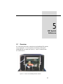
5
DIP Switch
Reference
5.1
Overview
DIP switch settings are used to customize the way DataBridge SDR operates
for your application. You can access the DIP switches by removing the
DataBridge SDR front panel (see Figure 5.1). Table 5.1 summarizes each
DIP switch function.
Figure 5.1. Location of the DataBridge SDR DIP switches.
25
DIP Switch Reference
5.1.1
DataBridge SDR User’
s Manual rev 1.2
Enabling data port handshaking (switch 1)
If your serial data source supports it, you may wish to use switch 1 to enable
hardware handshaking using the RTS and CTS signal lines (see Table 5.1).
This prevents lost data during long disk seeks.
5.1.2
Enabling configuration port handshaking (switch 2)
You may also want to enable hardware handshaking for the configuration
port using switch 2 if you plan to download data using the serial port or if
you are using a slow computer and notice lost characters in the DataBridge
menus (see Table 5.1).
5.1.3
Reserved switches (switches 3 and 4)
Switches 3 and 4 are reserved and must be set to the off position (see Table
5.1).
5.1.4
Displaying and hiding menus (switch 5)
If you connect to the configuration port using a radio modem or other serial
link with a low data rate, you may wish use switch 5 (see Table 5.1) to hide
the configuration menus to make DataBridge SDR more responsive. When
menus are hidden, keystrokes still active menu functions.
5.1.5
Disabling buttons (switch 6)
You can use switch 6 to disable the DataBridge SDR front panel buttons
(see Table 5.1). Use this option if you control DataBridge SDR using only
the configuration port. This prevents accidental contact or switch failure
from returning DataBridge SDR to Stop mode. This option may be useful
when DataBridge SDR will operate for unattended for long periods of time.
5.1.6
Disabling indicators (switch 7)
When power saving is important, you can use switch 7 to disable the front
panel indicators as shown in Table 5.1. When the front panel indicators are
disabled, you can still communicate via the configuration port to determine
DataBridge SDR's current mode.
5.1.7
Disabling resume mode (switch 8)
If you are troubleshooting a problem with DataBridge SDR and have resume
mode turned on (see Section 4.4), you may need to use switch 8 to force
DataBridge SDR into Stop mode when you apply power. Once you've
gotten DataBridge SDR stopped, you can enable resume mode again using
switch 8 as shown in Table 5.1.
26
DataBridge SDR User’
s Manual rev 1.2
5.1.8
DIP Switch Reference
Initiator ID (switch 9)
DataBridge SDR is a SCSI initiator whose ID is, by default, set to 6. If you
are using a device that occupies SCSI ID 6, you may need to use switch 9 to
change the SCSI ID to 7 as shown in Table 5.1.
5.1.9
Setting configuration port baud rate (switches 10-12)
In some cases, you may wish to choose higher (or lower) data rates for the
configuration port. For example, you may need a lower speed if you wish to
configure, control, and monitor DataBridge SDR remotely using a radio
modem. You may need a higher speed if you intend to download data
through the serial port using XMODEM. Switches 10, 11, and 12 are used
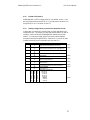
to select a baud rate for the configuration port (see Table 5.1).
switch
setting
off
on
off
on
off
on
off
on
off
on
off
on
off
on
off
on
off
on
1
2
3
4
5
6
7
8
9
function
disable hardware handshaking for the data port
enable hardware handshaking for the data port
disable hardware handshaking for the config. port
enable hardware handshaking for the configuration port
off
off
on
on
off
off
on
on
(switch must be off)
reserved
(switch must be off)
display menus
hide menus
enable the Stop, Play, and Record buttons
disable user interface buttons
enable indicators (LEDs)
disable indicators
enable resume mode
force DataBridge SDR into Stop mode on power-up
initiator SCSI ID=6
initiator SCSI ID=7
configuration port data rate
10:11:12
off
off
off
off
on
on
on
on
reserved
off
on
off
on
off
on
off
on
230,400 bps
115,200 bps
57,600 bps
38,400 bps
19,200 bps
9600 bps
4800 bps
2400 bps
(default)
(default)
(default)
(default)
(default)
(default)
(default)
(default)
Table 5.1. DIP switch settings
27
6
Troubleshooting
6.1
Frequently Asked Questions (FAQ)
Q: When I press the Record or Play button while in Stop Mode, the
indicators don’
t seem to respond quickly. What’
s wrong?
A: The Record and Play indicators only glow once data recording or
playback has begun. Slow media, disk fragmentation, or opening a large
existing file all require more preparation time before recording or playback
can begin.
As a rule, wait until the Record or Play indicator glows before transmitting
data or expecting to observe serial output. If the Record or Play indicator
doesn’
t glow after ten seconds, the disk may be full or may be experiencing a
hardware problem. Reset DataBridge SDR by removing and reapplying
power to see if it successfully enters Record or Play mode. If not, check the
disk for available space or media errors using a computer.
29
Troubleshooting
DataBridge SDR User’
s Manual rev 1.2
Q: Why does the Record indicator blink when DataBridge SDR is in Record
mode?
A: DataBridge SDR shuts off the record indicator momentarily while it
allocates disk clusters and updates directory entries. This “blinking”is
normal behavior intended to be used as a diagnostic tool and gauge of disk
performance and data volume.
Q: When I press the Record button, DataBridge SDR ejects my Zip disk.
Why?
A: DataBridge SDR ejects removable media and returns to Stop Mode
when it can no longer allocate clusters. Delete files from the Zip disk,
reformat it, or replace it. Sometimes disks with corrupt files cause disks to
appear full prematurely. Use ScanDisk, included with DOS or Windows
95™ to check your disk for allocation errors.
Q: I’
ve been using DataBridge SDR with a hard disk for about six months.
Why does it now stay in Stop Mode when I press the Record button?
A: As with the Zip disk, DataBridge SDR returns to Stop Mode when it can
no longer allocate disk clusters (DataBridge SDR obviously cannot eject a
hard disk).
Q: I checked my disk and it is only 99% full. However, DataBridge SDR
still ejects it when I press the record button. Why?
A: To maximize data integrity, DataBridge SDR allocates clusters in
advance. DataBridge SDR will enter Record mode only when it is able to
allocate these clusters. DataBridge SDR is designed to allocate only about
99% of the drives free space, leaving the last sector of the file allocation table
(FAT) free.
Q: Why does the date/time display in menu mode have a question mark
after it?
A: The date and time are shown with a question mark whenever the realtime clock’
s internal oscillator stops. This may occur when the battery
voltage is low or the battery is temporarily shorted or removed. If this
happens repeatedly, replace the real-time clock’
s battery.
30
DataBridge SDR User’
s Manual rev 1.2
Troubleshooting
Q: I want to use my own 5 VDC power supply with DataBridge SDR. How
do I connect it?
A: The power receptacle on the rear panel of DataBridge SDR is a Series 1
size 11 four-pin standard-sex AMP Circular Plastic Connector (CPC), AMP
part number 206061-1. The plug that connects to DataBridge SDR’
s power
receptacle is AMP part number 206060-1.
The connector’
s pinout is shown in Table 6.1.
pin
1
2
3
4
function
+5.0 VDC
ground
ground
+12.0 VDC (if needed)
Table 6.1. Power connector pinout.
Pay careful attention to DataBridge SDR’
s electrical specifications and
power requirements (see Appendix B).
Q: When I connect DataBridge SDR to my computer, why do I see garbage
on my screen?
A: Your terminal’
s baud rate and DataBridge SDR’
s baud rate do not
match. Unrecognizable characters may also be a symptom of mismatched
data formats (data bits, stop bits, parity).
Q: I changed my serial parameters in HyperTerminal and I still see garbage.
Why?
A: HyperTerminal requires that you “disconnect”and “reconnect”(from
the Call menu) before its serial parameters actually change.
Q: Why does HyperTerminal lock up/run very slowly when I connect it to
DataBridge SDR?
A: HyperTerminal does this when it expects handshaking signals and
doesn’
t get them. If you are patient, you can wait for HyperTerminal to
display its Call menu and choose “disconnect”(then disable hardware
handshaking) or you can enable DataBridge SDR’
s hardware handshaking
on the jumper block.
Q: I have a question that is not in this FAQ. How can I find an answer?
A: Call us, write us, or e-mail us. Your question may be one others have
and are afraid to ask. See Section 7.1 of the User’
s Manual for contact
information.
31
7
Service and
Support
7.1
Contacting Acumen Instruments
Corporation
7.1.1
Technical support
Service and technical support can be reached between the hours of 9AM and
5PM (Central Standard Time) Monday through Friday. Acumen Instruments
Corporation can be reached at the following phone numbers:
(515) 233-6560 (voice)
(515) 233-0078 (fax)
7.1.2
Mail
Acumen Instruments Corporation can be reached by mail at:
Acumen Instruments Corporation
209 S. Fifth Street #2
Ames, IA 50010-6848
USA
33
Service and Support
7.1.3
DataBridge SDR User’
s Manual rev 1.2
E-mail
Acumen Instruments Corporation can be reached via e-mail at:
[email protected]
7.1.4
World Wide Web
Acumen Instruments Corporation maintains a web site which contains
product information and downloads:
http://www.acumeninstruments.com
7.2
Returning Equipment
Before returning equipment to Acumen Instruments Corporation, please call
for an RMA number and shipping information. This allows us to plan for
your shipment in order to provide the best possible service. When returning
equipment, please include a note indicating the symptoms of the failure and
any other pertinent information.
7.3
Warranty
7.3.1
One year warranty
Acumen Instruments Corporation warrants this product to be free from
defects in materials and workmanship for a period of one (1) year from the
date of shipment. During the warranty period, Acumen Instruments
Corporation will, at its option, either repair or replace products that prove to
be defective.
7.3.2
Exclusions
This warranty shall not apply to any defect, failure or damage caused by
misuse, abuse, improper application, alteration, accident, disaster,
negligence, use outside of the environmental specifications, improper or
inadequate maintenance, or incorrect repair or servicing not performed or
authorized by Acumen Instruments Corporation.
34
DataBridge SDR User’
s Manual rev 1.2
7.3.3
Service and Support
Limitations
ACUMEN INSTRUMENTS CORPORATION SHALL IN NO EVENT HAVE
OBLIGTIONS OR LIABILITIES TO BUYER OR ANY OTHER PERSON FOR LOSS OF
PROFITS, LOSS OF USE OR INCIDENTAL, SPECIAL, OR CONSEQUENTIAL
DAMAGES, WHETHER BASED ON CONTRACT, TORT (INCLUDING
NEGLIGENCE), STRICT LIABILITY, OR ANY OTHER THEORY OR FORM OF
ACTION, EVEN IF ACUMEN INSTRUMENTS CORPORATION HAS BEEN ADVISED
OF THE POSSIBILITY THEREOF, ARISING OUT OF OR IN CONNECTION WITH THE
SALE, DELIVERY, USE, REPAIR, OR PERFORMANCE OF THIS PRODUCT
(INCLUDING EQUIPMENT, DOCUMENTATION AND SOFTWARE). IN NO EVENT
SHALL THE LIABILITY OF ACUMEN INSTRUMENTS CORPORATION ARISING IN
CONNECTION WITH ANY PRODUCT EXCEED THE ACTUAL AMOUNT PAID FOR
SUCH A PRODUCT.
THIS WARRANTY IS IN LIEU OF ALL OTHER WARRANTIES, WRITTEN OR ORAL,
EXPRESSED OR IMPLIED, INCLUDING IMPLIED WARRANTIES OR
MERCHANTABILITY OR FITNESS FOR A PARTICULAR PURPOSE.
35
A
DataBridge SDR
Evaluation Kit
A.1 Overview
The evaluation kit is intended for use by those familiarizing themselves with
DataBridge technology for custom applications. Housed in an attractive
desktop enclosure, the evaluation system is also suitable for use in laboratory
and other protected environments.
Figure A.1. DataBridge SDR evaluation kit (shown equipped with
an Iomega Zip™ drive).
37
DataBridge SDR Evaluation Kit
DataBridge SDR User’
s Manual rev 1.2
The evaluation kit includes an integral 120/240 VAC power supply, mass
storage device, and necessary cabling. Because it contains the DataBridge
OEM circuit board, the evaluation kit is functionally identical to DataBridge
SDR.
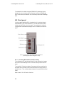
A.2 Front panel
Like the rugged DataBridge SDR, the evaluation kit is controlled using its
illuminated stop, play, and record buttons. The data indicator and power
indicator are also found on the front panel. The evaluation kit is typically
configured with removable mass storage, which is accessible from the front
panel.
Figure A.2. Front panel of the DataBridge SDR evaluation kit
(shown equipped with an Iomega Zip™ drive).
A.2.1
Accessing DIP switches and RTC battery
The configuration DIP switches (see Figure 5.1) and real-time clock battery
are found on the DataBridge OEM circuit board, directly behind the front
panel.
To access the DIP switches or battery, first remove the four screws found in
the rubber feet on the base of the unit and remove the housing by sliding it
toward the rear. Then, carefully detach the plastic front panel from the steel
frame.
Refer to Table 5.1 for DIP switch functions.
38
DataBridge SDR User’
s Manual rev 1.2
DataBridge SDR Evaluation Kit
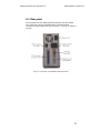
A.3 Rear panel
On the rear panel of the DataBridge SDR evaluation kit are the 120/240
VAC power cord connector and power switch, the DB9 serial port
connectors, and the Centronics-50 SCSI connector. The SCSI ID selector is
not used.
Figure A.3. Rear panel of the DataBridge SDR evaluation kit.
39
B
Serial Port Basics
B.1 Serial specifications
Serial data is any data that is sent one bit at a time using a single electrical
signal. In contrast, parallel data is sent 8, 16, 32, or even 64 bits at a time
using a signal line for each bit. Data that is sent without the use of a master
clock is said to be asynchronous serial data.
Several communications standards exist for the transfer of asynchronous
serial data. Common PC’
s transfer data using the EIA RS-232C (also known
as V.28 or V.24). Updated versions of this standard include RS-232D and
EIA/TIA-232E, but most literature still refers to the RS-232C or RS-232
standard.
Other asynchronous serial standards in common use include RS-422, RS423, and RS-485. These standards allow higher data rates and longer cable
lengths than RS-232 and are common in industrial settings.
B.2 Data rates
The baud rate for a serial connection is the number of bits that are
transmitted per second. It is specified in bits/second or baud. For example,
a 9600 baud serial link transfers 9600 bits per second.
41
Serial Port Basics
DataBridge SDR User’
s Manual rev 1.2
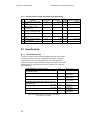
The EIA RS-232C standard permits data rates up to 19200 bps and cable
lengths up to 400 meters (but not both).
data rate
(bps)
19200
9600
4800
2400
1200
600
maximum distance
(meters)
(feet)
15
45
25
76
50
152
100
304
200
608
400
1216
Table B.1. Data rates and distances for RS-232 communications.
Although the specification only defines rates up to 19200 bps,
communication using data rates as high as 230400 bps and a short (<2
meter) cable is common. Standard modems communicate with computers at
up to 115200 bps.
As you may have guessed, the use of high baud rates requires more capable
computer hardware. At high baud rates, a computer must process as many
as 23000 characters per second. The constant attention a computer must
pay to its serial port makes this problematic particularly in multitasking
environments such as Microsoft Windows 3.1/95/98/NT.
B.2.1
Data rates and the UART
Computer hardware designers solve this problem by allowing the computer
to respond to characters less frequently. A Universal Asynchronous
Receiver/Transmitter (UART), the component responsible for
communicating via RS-232, may contain several bytes of memory called a
FIFO (first-in, first-out memory).
The original IBM PC (and many of its successors) used the 8250 UART,
which contained no FIFO. That is, a computer with 8250 (or 16450)
UART’
s must respond to every incoming character.
Newer PC’
s incorporate the 16550 UART or a variant. The 16550
incorporates a 16-byte FIFO and is mandatory for communications at
speeds above 9600 bps and is important for error-free communications at
lower speeds as well.
You can find out which type of UART’
s your computer uses by using the
MSD.EXE tool provided with DOS and Windows or by looking in the
Windows 95/98 control panel.
42
DataBridge SDR User’
s Manual rev 1.2
Serial Port Basics
B.3 More asynchronous serial parameters
In most cases, the data rate in bytes/second can be approximated by dividing
the baud rate (in bits/second) by 10. If a byte consists of 8 bits, why divide
by 10?
To transfer data asynchronously, the UART must frame the 8 data bits
between a stop bit and a start bit. The start bit is always a zero, while the
stop bit is always a one. So, a byte of data sent serially is made up of 10 bits
instead of the usual 8.
Asynchronous serial devices can communicate using 7 or 8 data bits, and 1,
1½ , or 2 stop bits. To further complicate matters, devices can also employ a
parity bit instead of an eighth data bit to check for errors. Even parity
systems transmit a one when the sum of the seven bits is an even number,
while odd parity systems transmit a one when the sum is odd. Still more
exotic systems may specify “mark”or “space”parity, where the parity bit is
always a one or zero, respectively.
What does all of this mean? Device vendors usually specify their data rate
and format using statements like “9600, 8N1”, which translates to 9600 bps,
8 data bits, no parity, and 1 stop bit or “19200, 7E1”, which translates to
19200 bps, 7 data bits, even parity, and 1 stop bit.
B.3.1
DTE and DCE
The RS-232 specification defines two classes of devices: data terminal
equipment (DTE) and data communication equipment (DCE). Your
computer’
s serial port is configured for DTE operation, since the computer
acts as a terminal. Modems and many other serial devices are configured as
DCE, since they are communications equipment.
What’
s the difference? A DTE device’
s TD signal means “I transmit data on
this line.” A DCE’
s TD signal can be read “You (the DTE) transmit data to
me on this line.” A DTE’
s RD signal means “I receive data on this signal
line.” A DCE’
s RD line means, “You, the DTE, will receive the data I
transmit on this signal line.” Sound confusing?
A look at a the DB9 connector pinouts and signal direction with respect to
DTE (e.g. your computer) makes things a little more clear.
43
Most serial devices
format of eight data
bits, no parity, and one
stop bit (8N1).
Serial Port Basics
DataBridge SDR User’
s Manual rev 1.2
signal name
transmitted data
received data
request to send
clear to send
data terminal ready
data set ready
data carrier detect
ring indicator
signal ground
TD
RD
RTS
CTS
DTR
DSR
DCD
RI
GND
pin number
25-pin
9-pin
2
3
3
2
4
7
5
8
20
4
6
6
8
1
22
9
7
5
direction
DTE? DCE
DTE? DCE
DTE? DCE
DTE? DCE
DTE? DCE
DTE? DCE
DTE? DCE
DTE? DCE
Table B.2. Pinouts for 9-pin and 25-pin serial connectors.
The cable that connects DTE devices (such as your computer) and DCE
devices (such as your modem) is simple. It simply connects TD pin to TD,
pin RD to RD, etc. A cable that connects DTE to DTE or DCE to DCE
must connect the TD to RD and RD to TD. This cable is referred to as a
null modem cable because it can connect two terminals (DTE’
s) without the
use of modems (DCE’
s). Note that GND pins are always connected.
Most devices have female connectors (DB9 or DB25) if they are configured
for DCE operation and male connectors if they are configured for DTE
operation, but this is not always the case.
There is a simple trick for determining whether a device is DTE or DCE.
Connect a voltmeter’
s ground line to the connector’
s GND pin. Then,
probe the voltage on the TD and RD pins. If the TD pin voltage is small (3V<Vin<+3V), the device is configured to receive data on the TD pin, and
thus is a DCE device. Likewise, if the RD pin voltage is small, the device is
receiving data on the RD pin, and thus is DTE.
B.3.2
Handshaking
Handshaking signals by the receiving device to tell the transmitter “I am
ready for data”or “I am not ready for data.” These signals are optional: the
receiver may always be ready for data or may choose to simply discard data it
couldn’
t process.
A DTE device asserts the “request to send”(RTS) signal when it is ready to
receive data and deasserts it when it cannot accept data. Likewise, a DCE
device asserts “clear to send”(CTS) when it is ready to receive data. The
RTS and CTS signals form a handshaking pair, and their use constitutes
RTS/CTS handshaking.
The “data terminal ready”(DTR) signal, asserted by the DTE, and the “data
set ready”(DSR), asserted by the DCE serve similar functions and
constitute DTR/DSR handshaking. A DTE or DCE devices may employ
either or both forms of handshaking. Often, deasserting RTS or CTS signals
“micro”events, such as a full buffer that is full but will be empty soon, while
44
DataBridge SDR User’
s Manual rev 1.2
Serial Port Basics
deasserting DTR or DSR may signal “major”events such as that power has
not been applied.
RTS/CTS handshaking and DTR/DSR handshaking are both referred to as
hardware handshaking. Another form of handshaking, XON/XOFF or
software handshaking, requires that the receiver send a character (Control-S,
ASCII 19) to halt data transfer and another character (Control-Q, ASCII
17) to resume transfer. Although this method eliminates the need for the
RTS, CTS, DTR, or DSR signals, it suffers from slow response time by the
receiver and renders 2 characters of the 256-character ASCII set unusable.
At data transfer rates above 9600 bps, it is important to employ handshaking
wherever possible even when UARTs with FIFO buffers are used.
Remember that at 115200 bps, a 16-byte FIFO fills in only 1.3 milliseconds,
while many mass storage devices advertise average seek times of 20-30
milliseconds.
B.3.3
Voltage levels
For noise immunity and long cable lengths, RS-232 devices convert
TTL/CMOS-level signals (0V=logic zero, +5V or +3.3V=logic one) to
higher voltage bipolar signals. For the TD and RD signal lines, RS-232
devices use a voltage between –3V and –25V to transmit a one and a voltage
between +3V and +25V to transmit a zero. For the other signal lines (RTS,
CTS, etc.), RS-232 devices use +3V to +25V to assert the signal and –3V to
–25V to deassert the signal. These voltage levels are defined in the
EIA/TIA-232E specification. So, when a DTE devices drives RTS at –
9.50V, it is signaling the DCE to stop sending data.
A few devices, particularly devices that communicate at low data rates or
over short cables, bypass the voltage conversion altogether. These devices
often require “computer interface kits”that are really no more than a level
converter in a box. These serial ports are often referred to as TTL RS-232,
CMOS RS-232, or 5 Volt RS-232 ports and require level converters to
interact with computers and other serial devices.
45
C
DataBridge SDR
Electrical
Specifications
C.1 Power requirements
DataBridge SDR itself requires only a regulated +5VDC power source.
Additional power requirements depend on the installed recording media. A
typical hard disk requires 5-15W during operation (after spinup). Some
disks require 5VDC while others require both +5VDC and +12VDC
power. Solid-state disks require 2W (112 MB model) at +5VDC, which
keeps power requirements for the entire system to a single +5VDC supply.
The Iomega Zip™ drive requires only +5VDC. Table C.1 outlines power
consumption with an Iomega Zip™ drive installed.
DataBridge SDR circuit board
DataBridge SDR with Iomega Zip™ Drive
Stop mode
+5VDC
60mA
+5VDC
Play mode
+5VDC
Record mode
+5VDC
550mA avg.
1200mA peak
800mA avg.
1200mA peak
800mA avg.
1200mA peak
Table C.1. DataBridge SDR power consumption with Iomega Zip™
drive installed.
47
DataBridge SDR Electrical Specifications
DataBridge SDR User’
s Manual v0.01
DataBridge SDR is also available with an optional 120/220VAC power
supply. Its power requirements are as listed in Table C.2.
120/220 VAC External Power Supply
input voltage
input frequency
input current
100-250 VAC
50-60 Hz
1.2 A
Table C.2. Power requirements for optional AC power supply.
C.1.1
Power receptacle pin configuration
pin
1
2
3
4
function
+5.0 VDC
ground
ground
+12.0 VDC (if needed)
Table C.3. The DataBridge SDR power receptacle pin
configuration.
C.2 Serial communications
serial port
electrical interface compliance
data rates
stop bits
parity
handshaking
EIA/TIA-232E and V.28
300, 1200, 2400, 4800, 9600, 19200,
38400, 57600, 115200, 230400 bps
1 or 2
none, even, odd
RTS/CTS, DTR/DSR
Table C.4. Serial communications specifications for DataBridge
SDR.
C.3 SCSI interface
SCSI interface
SCSI compliance
electrical interface
SCSI transfer mode
SCSI commands
storage capacity
ANSI SCSI standard X3.131-1994
single-ended SCSI
8-bit asynchronous
industry-standard SCSI command set
limited only by storage device and FAT file system
Table C.5. SCSI interface specifications for DataBridge SDR.
48
D
DataBridge SDR
Mechanical
Specifications
D.1 Dimensions
DataBridge SDR circuit board
dimensions
weight
DataBridge SDR in extruded aluminum
enclosure
dimensions
weight (with Iomega Zip™ drive installed)
4.00”L × 3.00”W × 0.40”H
(10.2 cm × 7.6 cm × 1.0 cm)
approx. 1.0 oz. (28.3 grams)
11.50”D × 7.75”W × 4.20”H
(29.2 cm × 19.7 cm × 10.7 cm)
7lbs. 1oz. (3.2 kg)
Table D.1. DataBridge SDR dimensions.
DataBridge SDR is also available with an optional 120/220VAC power
supply. Its dimensions are as listed in Table D.2.
120/220 VAC External Power Supply
dimensions
output cord length
6.00”L × 3.25”W × 2.00”H
(15.25 cm × 8.25 cm × 5.08 cm)
approx. 72”(183 cm)
Table D.2. Dimensions for optional AC power supply.
49
DataBridge SDR Mechanical Specifications
DataBridge SDR User’
s Manual rev 1.2
D.2 Environment
DataBridge SDR’
s extruded aluminum enclosure, buttons and connectors
are designed to, at a minimum, meet the IEC 144/855420 I.P. 65 rating
(dust tight and protected against water jets) and the equivalent NEMA 12
rating (industrial use, dust tight and drip tight).
DataBridge SDR in extruded
aluminum enclosure
operating ambient temperature
relative humidity
altitude
0-50°C
up to 100% R.H., condensing
100,000 ft (limited by recording media only)
Table D.3. DataBridge SDR environment specifications.
Note: The optional external 120/220VAC power supply is not rated for use
in an unprotected environment. For harsh environments an appropriate
power supply should be used.
D.2.1
Desiccant
When used with removable recording media, the interior of the DataBridge
SDR enclosure may be exposed to humidity when the front panel is removed
to access the media. To avoid condensation inside the enclosure, the use of
desiccants is recommended in humid environments.
A desiccant’
s effectiveness will vary depending on the number of times the
front panel is removed and the relative humidity in the when the front panel
is removed. Monitor the humidity inside the enclosure with a disposable
humidity indicator and change desiccant as needed.
A wide range of desiccant products are available from:
United Desiccants
101 Christine Drive
Rio Grande Industrial Park
Belen, NM 87002
(800) 989-DESI
(505) 864-6691
(505) 864-9296 FAX
Humidity indicators are available from:
Humidial Corporation
926 So. 8th Street
PO Box 610
Colton, CA 92324-0610
(909) 825-1793
(800) 966-1793
(909) 825-6271 FAX
50
E
The Switch
Closure
Interface
E.1 Description
The Switch Closure Interface (SwCI) is designed to provide an electrically
isolated and buffered interface to the DataBridge SDR. A DataBridge SDR
equipped with the SwCI will timestamp and log switch openings and
closings.
The SwCI can monitor up to sixteen switch inputs (organized as two 8switch ports). DataBridge SDR, when equipped with an SwCI, has two
additional AMP CPC 13-9 receptacles on the rear panel— one for each 8switch port (see Figure E.4).
E.2 Operation
To use the Switch Closure Interface, first connect the AMP CPC-to-screw
terminal cables to the appropriate ports on the rear panel of your
DataBridge SDR (see Figure E.4). Then, attach normally-open (NO) or
normally-closed (NC) switches to the screw terminals. Once switches are
connected to the SwCI, you can verify normal operation of the SwCI.
51
The Switch Closure Interface
DataBridge SDR User’
s Manual rev 1.2
Figure E.4. The DataBridge SDR rear panel with SwCI installed.
With DataBridge SDR’
s front panel removed, sixteen indicators on the front
of the SwCI are exposed (see Figure E.5). If DataBridge SDR and the
Switch Closure Interface are operating properly, any closed switch will light
the corresponding indicator while DataBridge SDR is in Record mode. If
possible, verify the operation of all switches connected to the SwCI by
observing the indicators without the front panel.
Figure E.5. Sixteen indicator LED's for the SwCI.
With DataBridge SDR’
s front panel in place and DataBridge SDR in Record
mode, you can test the SwCI by generating switch events (i.e. by changing
the state of any switch connected to the SwCI) and observing the data
indicator on DataBridge SDR’
s front panel. If DataBridge SDR and the
SwCI are working properly, the data indicator (see Figure 1.1) should light
as switches are opened or closed. Section 3.2.1 explains the function of the
data indicator.
52
DataBridge SDR User’
s Manual rev 1.2
The Switch Closure Interface
Figure E.6. Connection of switches to the screw terminals.
Figure E.7. Amp CPC-to-screw terminal cable. One of two used
for connecting to the Switch Closure Interface (SwCI).
53
The Switch Closure Interface
DataBridge SDR User’
s Manual rev 1.2
E.3 Switch Closure Interface Data Format
The Switch Closure Interface generates a line of telemetry on any switch
transition, either open-to-closed or closed-to-open. Parsing data for only a
single switch or single transition type (open or closed) is easily accomplished
using a “grep”utility or the DOS “FIND”command.
The SwCI telemetry follows the format:
SW,EVENT,MM/DD/YY,HH:MM:SS,COUNTER
Table E.1 describes each of the telemetry’
s comma-delimited fields.
switch #
event type
date
time
event counter
Switch that generated the event.
There are two sets of eight inputs A1-A8 and B1-B8.
Indicates whether the switch opened or closed.
Both types of events are recorded, so the SwCI is
suitable for use with both normally-open or normallyclosed switches.
The date of the event.
Rolls from “99”to “00”to for the year 2000.
The time of the event.
Recorded in 24-hour format.
Sequential counter.
This number is incremented for each event and helps
determine if any data is lost or out of sequence.
Table E.1. Fields in an SwCI telemetry string.
A1,close,05/01/98,09:10:39,00000001
A1,open, 05/01/98,09:10:45,00000002
B3,close,05/01/98,17:21:17,00000003
B3,open, 05/01/98,17:21:56,00000004
Figure E.8. Sample SwCI telemetry strings.
54
J2
J1
33mF
C1
4.75 kW
R3(d)
470 W
R1(d)
4.75 kW
R3(g)
4.75 kW
R3(h)
470 W
R1(g)
470 W
R1(h)
R4(b)
4.75 kW
R4(c)
4.75 kW
R2(b)
470 W
R2(c)
470 W
55
R4(g)
4.75 kW
R4(h)
R2(g)
470 W
R2(h)
R4(f)
4.75 kW
R2(f)
470 W
R4(e)
4.75 kW
470 W
4.75 kW
R2(e)
470 W
R4(d)
4.75 kW
470 W
R2(d)
R4(a)
R2(a)
U4
R3(f)
R1(f)
4.75 kW
4.75 kW
470 W
470 W
R3(e)
R1(e)
U3
R3(c)
R1(c)
4.75 kW
4.75 kW
470 W
U2
R3(b)
R1(b)
470 W
4.75 kW
470 W
4.75 kW
R3(a)
U1
GND
Vdd
R1(a)
470 W
Isolated
GND
Isolated
+5V
U10
13
12
11
9
10
14
15
16
17
18
19
8
7
6
5
4
3
2
20
11
10
1
12
9
14
15
16
17
18
19
20
13
U6
U5
8
7
6
5
4
3
2
1
0.1mF
C2
0.1mF
C3
0.1mF
C4
0.1mF
C5
0.1mF
C6
0.1mF
C7
7
10
9
8
7
6
5
4
3
2
1
10
9
8
7
6
5
4
D cQ
D cQ
D cQ
D cQ
D cQ
D cQ
D cQ
D cQ
U9
D cQ
D cQ
D cQ
D cQ
D cQ
D cQ
D cQ
11
12
13
14
15
16
17
18
19
20
11
12
13
14
15
16
17
18
19
3
20
2
D cQ
1
U8
8
9
11
4
10
12
3
6
13
2
5
14
U7
1
A1
A3
A5
A7
B1
A2
A4
A6
A8
B2
B4
B6
B5
B3
B8
GND
GND
B7
Vdd
Vdd
J4
SDI
SDO
RE3
SCK
RE1
SS
D0
RE2
D2
RE0
D4
D1
D6
D7
D3
RD
WR
D5
GND
Vdd
J3
2. Schematic
LED1 (A1)
LED2 (A2)
LED3 (A3)
LED4 (A4)
LED5 (A5)
LED6 (A6)
LED7 (A7)
LED8 (A8)
LED9 (B1)
LED10 (B2)
LED11 (B3)
LED12 (B4)
LED13 (B5)
LED14 (B6)
LED15 (B7)
LED16 (B8)
DataBridge SDR User’
s Manual rev 1.2
The Switch Closure Interface
E.4 Schematic
The Switch Closure Interface
DataBridge SDR User’
s Manual rev 1.2
C7
U7
TC74HC574A
U8
Vcc
Q0
Q1
Q2
Q3
Q4
Q5
Q6
Q7
CK
C4
OE
D0
D1
D2
D3
D4
D5
D6
D7
GND
R2
C5
U3
1B
2Y
2A
4Y
U6
LED16
B8
LED15
B7
LED14
B6
LED13
B5
LED12
B4
LED11
B3
LED10
B2
LED9
B1
LED8
A8
LED7
A7
LED6
A6
LED5
A5
LED4
A4
LED3
A3
LED2
A2
LED1
A1
4B
4A
3Y
3B
3A
J5
G1
A1
A2
A3
A4
A5
A6
A7
A8
GND
R4
56
1A
GND
TC74HC541
U4
Vcc
1Y
2B
Vcc
G2
Y1
Y2
Y3
Y4
Y5
Y6
Y7
Y8
J2
C6
TC74HC02
U5
G1
A1
A2
A3
A4
A5
A6
A7
A8
GND
R3
C1
U2
TC74HC541
U9
Vcc
Q0
Q1
Q2
Q3
Q4
Q5
Q6
Q7
CK
C3
TC74HC574A
Vcc
G2
Y1
Y2
Y3
Y4
Y5
Y6
Y7
Y8
U1
C2
OE
D0
D1
D2
D3
D4
D5
D6
D7
GND
J1
J4
IN+
IN-
OUT-
OUT+
R1
U10
E.5 PCB Component Locations
DataBridge SDR User’
s Manual rev 1.2
The Switch Closure Interface
E.6 Bill of Materials
E.6.1
QTY
1
6
2
2
16
2
2
4
2
2
2
1
DESIGN
ATION
DESCRIPTION
MANUFACTURER
C1 33µF/16V tantalum chip capacitor,
TE Series
C2-C7 0.1µF/50V ceramic chip capacitor,
1206 SMD
J1, J2 0.100”shrouded header, gold, 10position, straight
J3, J4 0.100”shrouded header, gold, 20position, straight
LED1- 5V, T1-3/4, red diffused LED
LED16
R1, R2 Bussed, 10-pin, 9-resistor, 470O,
±2%, CSC Series
R3, R4 Bussed, 10-pin, 9-resistor, 4.7kO,
±2%, thick-film conformal SIP
U1-U4 Optocoupler, 4-channel, SMD,
transistor output
U5, U6 Octal Bus Buffer, 20-pin wide
SOIC
U7 Quad 2-input NOR gate, 14-pin
narrow SOIC
U8, U9 Octal D Flip-Flop, 20-pin wide
SOIC
U10 Isolated DC-DC converter, 1W,
5V/5V single output
E.6.2
QTY
Switch Closure Interface: Circuit Board
MANUFACTURER
PART NUMBER
VENDOR
VENDOR PART NUMBER
Panasonic
ECS-T1CD336R Digi-Key
PCS3336CT-ND
Panasonic
ECU-V1H104KBW Digi-Key
PCC104BCT-ND
3M
2510-6002UB Digi-Key
MHB10K-ND
3M
2520-6002UB Digi-Key
MHB20K-ND
MR3050 Digi-Key
MR3050QT-ND
CSC10A-01-471G Newark
81F4857R470.0
4610X-101-472 Digi-Key
4610X-1-472-ND
PS2701-4 Digi-Key
PS2701-4NEC-ND
Toshiba
TC74VHC541FW Digi-Key
TC74VHC541FW-ND
Toshiba
TC74VHC02FN Digi-Key
TC74VHC02FN-ND
Toshiba
TC74VHC574FW Digi-Key
TC74VHC574FW-ND
DSP1N5S5 Digi-Key
DSP1N5S5-ND
QT
Optoelectronics
Vishay-Dale
Bourns
NEC
Power One
Switch Closure Interface: Internal Cable Assemblies
DESCRIPTION
2 0.100”10-pin gold socket
connector w/key, w/strain relief
2 12”-10 conductor ribbon cable,
28AWG, stranded 7x36, 0.050”
pitch, gray PVC
2 Amp CPC Series 1, size13-9
receptacle, sq. flanged, sealed,
std. sex
9 Amp CPC Series 1 pins, gold, 2420 AWG, crimp
2 Amp CPC size 13 connector cap,
circular seal, w/chain
4 4-40x0.375”stainless steel socket
head cap screw
4 4-40 stainless steel machine
screw nut
4 #4 stainless steel medium lock
washer
MANUFACTURER
CW Industries
MANUFACTURER
PART NUMBER
VENDOR
VENDOR PART NUMBER
CWR-217-10-0000 Digi-Key
CKR10G-ND
Belden
9L28010 Newark
36F652WA
Amp
206705-3 Digi-Key
A1669-ND
Amp
66400-4 Digi-Key
A1648-ND
Amp
213485-1 Digi-Key
A16043-ND
Brikksen
Hokel
SSSHCS004003
Brikksen
Hokel
SSHN004
Brikksen
Hokel
SSLW004
57
The Switch Closure Interface
E.6.3
QTY
DataBridge SDR User’
s Manual rev 1.2
Switch Closure Interface: External Cable Assemblies
DESCRIPTION
2 Amp CPC Series 1, size13-9 plug,
std. sex
2 Amp CPC size 13 connector boot,
adhesive lined heat shrink
9 Amp CPC Series 1 sockets, gold,
24-20 AWG, crimp
2 3’-Belden Infinity-FCC (1 million+
Flex Cycles), 9x20 AWG (7x30)
16 0.125”x1”heat shrinkable tubing,
blue
18 0.125”x1”heat shrinkable tubing,
green
34 #6 terminal spade, 22-16AWG,
short, uninsulated
4 8-contact, 0.438”barrier block
MANUFACTURER
MANUFACTURER
PART NUMBER
VENDOR
VENDOR PART NUMBER
Amp
206708-1 Digi-Key
A1302-ND
Amp
54123-1 Digi-Key
A16047-ND
Amp
66399-4 Digi-Key
A1661-ND
Belden
7405A Newark
16F9504
3M
FP-301 Digi-Key
FP018B-5-ND
3M
FP-301 Digi-Key
FP018G-5-ND
Amp
36195 Digi-Key
A09001-ND
Cinch
8-141 Digi-Key
CBB208-ND
E.7 Specifications
E.7.1
Power Requirements
The Switch Closure Interface receives its power through the internal cable
connecting the SwCI to the main DataBridge circuit board. The power
consumed by the SwCI will vary depending on how many switches are
closed, since the optocoupler will draw about 10mA per closed switch, and if
DataBridge SDR is in Record mode, since the indicator LED’
s consume
about 13mA each.
DataBridge SDR circuit board and SwCI
DataBridge SDR and SwCI with Iomega Zip™ Drive
(no switches closed)
Stop mode
+5VDC
approx. 100mA
+5VDC
Play mode
+5VDC
Record mode
+5VDC
600mA avg.
1250mA peak
850mA avg.
1250mA peak
850mA avg.
1250mA peak
DataBridge SDR and SwCI with Iomega Zip™ Drive (all
switches closed)
Stop mode
+5VDC
Play mode
+5VDC
Record mode
+5VDC
Table E.2. DataBridge SDR power consumption with SwCI and
Iomega Zip™ drive installed.
58
760mA avg.
1410mA peak
1200mA avg.
1450mA peak
1200mA avg.
1450mA peak
DataBridge SDR User’
s Manual rev 1.2
E.7.2
The Switch Closure Interface
Isolation
The Switch Closure Interface is designed to provide electrical isolation
between it’
s circuitry and the screw terminals. The optocouplers and
isolated DC-DC converter provide more than 500VDC isolation.
E.7.3
Switch sampling rate
The Switch Closure Interface samples the screw terminals every 5
milliseconds for an effective update rate of 200Hz. To debounce the inputs,
the Switch Closure Interface requires successive events before recording
data.
59