1
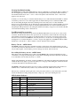
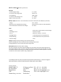
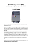
MPPTLA-PR281 Solar Load Controller & Maximum Power Point Tracking Unit User Manual Thank you for purchasing this state of the art product. This product has been designed to provide years of trouble free service. Introduction This unit serves as a mini DB to any low cost home, RDP house, bush house, stable living area, store room, shed, work area or any area, which requires lighting and there is no electricity available and solar can be a way of illumination. This is also a simple way to bring off grid lighting to any area in which lighting is required, or even as a mains failure back up. Installation is simple and can be done by anyone with a few siple tools. The latest PWM proprietary algorithms technology controls the solar panel to always supply the most efficient power, it also controls and monitors the state of a Lead Acid battery. It identifies the state that battery is in, indicates it’s status with LEDs, this constant control ensures best usage of the battery over it’s lifespan. When the battery reaches a critical value, the controller will disconnect the battery to safeguard the battery, until the next charge. The unit does have an override switch, which can be used in cases where lighting is critical, and will stay connected until the battery is completely discharged. The unit comes with 4 switchable circuits, 3 anytime On/Off, and 1 as a Day/Night switch to control a night or security light circuit. Which model is right for you? The most important part when selecting the model for your application, is to calculate the amount of lighting required, and for how long the lights are to remain running on the battery. Once this has been calculated, speak to your dealer on the correct selection for your application. A number of combinations available to fit your requirements. LA09 – use a 20W solar panel and a 9A deep discharge lead acid battery LA18 – Use a 30W solar panel and an 18A deep discharge lead acid battery LA25 – Use a 55W solar panel and an 25A deep discharge lead acid battery LA45 – Use a 70W solar panel and an 45A deep discharge lead acid battery 1 Typical discharge times for the different batteries:If you use our proprietary lights, which provide 240Lumens of light from 2W of consumption, you can use the following table to calculate the system suitable for your application. Battery Capacity Hours- 2W Load Hours - 4W Load Hours - 8W Load Number of lights 9A 1 lamp 2 lamps 4 lamps 27 13.5 6.75 18A 54 27 13.5 25A 75 37.5 18.75 45A 135 67.5 33.75 Electrical connection – Solar Panel Incorrect connection of the PV panel will void the MPPTLA unit warranty. Connect the PV, ensuring that the PV wire polarity matches the unit to the terminals marked ‘PV+’ and ‘PV-‘. ‘PV+’ refers to the positive side and ‘PV-‘ refers to the negative side of the PV panel. If the polarity is correct, and the sun is shining directly on the PV panel, then the orange PV LED will be lit. Electrical Connection – Battery Incorrect connection of the Battery will void the MPPTLA unit warranty. If the battery wires are incorrectly inserted into the unit, the fuse should immediately blow because of reverse polarity. Making this type of error may damage the unit permanently. Care should be taken to ensure that the polarity is correct. The controller has no internal fuse for protection. For safety reasons and for protection, use 10Amp fuse in an inline Fuse holder with a fast blowing fuse, In the case of capacitive loads, where switching on may blow the fuse, then use a slow blow fuse, but do not use a fuse greater than 10Amps. This fuse will protect the unit, the wires and the battery against fire in case of a load fault, wiring fault or a catastrophic failure of the unit. Connect the battery, ensuring that the Battery wire polarity matches the unit to the terminals marked ‘Batt. +’ and ‘Batt. -‘. ‘Batt. +’ refers to the positive side of the battery, where the battery may have a number of marking types, depending on the manufacturer. A printed ‘+’ or text ‘Pos’ or a Red terminal washer will indicate the Positive side of the battery. ‘Batt. -‘ refers to the negative side of the battery. A printed ‘-‘ or text ‘Neg’ or a Black terminal washer will indicate the Negative side of the battery. Electrical Connection – Load Incorrect connection of the load will void the warranty both to the MPPTLA unit and the load. The unit uses a semiconductor, known as a FET to switch the load on and off. The FET makes a connection between the load negative line, and the battery negative line. On no circumstances do you connect the load to any other terminal of the MPPT unit than the ‘Sw1 +/- to Sw4 +/-’ terminals. It is not necessary to have any fuse in line to the load for protection, as there is a thermal fuse that protects the load in case of a short circuit or overload, and there is secondary protection fuse on the battery ‘Positive’ line will protect the system against any faults that may occur on the load side. Connect the load, ensuring that the load wire polarity matches the unit to the terminals marked ‘Sw1+ and -’,’Sw2+ and -’, ‘Sw3 + and -’ and ‘Sw4 + and -’. ‘Sw +’ refers to the positive side of the load. ‘Sw -‘ refers to the negative side of the load. 2 Selecting Day/Night Switching The MPPT unit has a built in Day/Night function, such as a night light or security light. This is available on the ‘Sw4 Night Light’ terminal. Connect the load, ensuring that the load wire polarity matches the unit to the terminals marked ‘Sw4+ and -’. ‘Sw4 +’ refers to the positive side of the load. ‘Sw4 -‘ refers to the negative side of the load. At dusk, as soon as the sun goes down, the internal microprocessor will switch the internal FET on, and the load will be powered. As soon as dawn approaches, the internal microprocessor switches the FET off. In the case that during the night, if the battery discharges below the safety level of 11.0V, the internal microprocessor will switch the load off, and will only again switch the load on at the next night cycle, if the battery gets charged beyond 12V. There is an internal latch which will lock out the load till the battery is charged again. This prevents the load cycling On and Off as the battery voltage recovers from the switched off load and the discharge of the connected load. Load Electronic Fuse protection The unit has a unique electronic fuse protection mechanism. When there is an overload, or a short on the load wires, the thermal fuse will become open circuit. To reset the fuse, switch off all the loads using the panel switches, and switch one switch on at a time and wait a few seconds to see if it trips. If it does trip, then remove the load from the MPPTLA, and verify the wires to see the reason for the tripping. It may be shorting wires or a load that has failed, or a load too large for the application. An LED will indicate which channel is in overload. OL1 – will be switches 1,2 and 3, and OL2 will be switch 4. Battery Cut out – audible buzzer The MPPTLA monitors the battery, and when it reaches a critical level, will sound the buzzer every few seconds to inform the user that the battery is at a critical level and will cut out without notice. The load will only be enabled again, once the battery goes into a charge cycle mode, and exceeds 12V Over riding the battery cut out – audible buzzer There may be times that lighting may be critical, and the MPPTLA has a feature in which the user may override the low voltage cut out. Doing this too many times will damage the battery chemistry, and should be avoided unless it is absolutely necessary to override. Simply push and hold the ‘Over Ride’ switch. The MPPTLA, will enable the output loads. During this time switch off unnecessary lights, to preserve the battery for as long as possible during the override mode. The ‘Override’ LED will be lit to indicate this mode. The MPPTLA will enable the buzzer every few seconds as a warning, and will again switch off the load within an hour, or when the battery reaches a very critical 10.5V level, whichever comes first. The user may override the system again, but at some point, there will be no power in the battery, and will remain off until the next charge brings the battery voltage up to 12V before enabling the load. LED Feedback Indicator LED Colour Indication OL1 Red Over Load on circuit Sw,Sw2,Sw3 OL2 Red Over Load on circuit Sw4 Override Red Over Ride Mode Batt Low Red Battery Low Batt OK Orange Battery has charge Batt Full Green Battery is full Boost Orange Boost mode PV Orange PV working 3 MPPTLA-PR281 Technical specifications PV Input PV Input Supply Voltage 0 – 27V D.C. PV Current at full charge mode 10mA- 4.5A PV Panel Rating 10W to 70W PV maximum load voltage value 17 – 18V DC MPPT Current with no load 10 - 15mA Battery Input (Not Fused – we recommend use an external 5Amp fuse max 10Amp for protection) Voltage 10.5 – 16V DC Maximum current absorbed at full charge 5A (PV Panel size and time of day dependant) Current draw with no load and no PV voltage 10 - 15mA Load Voltage greater than 11.0V to Battery terminal voltage Low voltage cut out Less than 11.0V DC Current Maximum is 4 Amps – not fused Day/Night switch 1 Channel Electronic Fuse protected 1A All day switching 3 Channels Electronic Fuse protected 3A Lock Out Voltage 10.5V Charger (Intelligent charger working in the parameters below) If battery voltage below 11.5V then Boost mode till voltage reaches 14.5V If voltage between 11.5V and 14.5V then trickle charge mode MPPT Mode (Maximum Power Point Tracking) The micro controller uses switch mode technology to ensure that the Solar Panel always operates at it most highest efficiency point at all times. Using this method it increases panel output by 30% over other conventional methods. Introducing this switching technology ensures that smaller PV panels can be used to achieve the same amount of power using a larger panel. In accordance with our policy of continual improvement, Microsolve C.C. reserve the right to alter specifications, materials and dimensions without prior notice. E&OE. Contact details: Simple Lights C.C. P.O. Box 61014 Marshalltown 2107 Johannesburg, South Africa 231 Booysens Road Cnr Webber Selby Johannesburg South Africa 4 Tel: +27 - 11 – 493-5110 Fax: +27 – 11 – 493-5114 Email: [email protected] Web: www.simplelights.co.za