1
SimpleComTools, LLC
XML1000 – User Manual
User Manual
&
Command Reference Guide
xml1000
Serial I/O Server
March 2006
SimpleComTools, LLC
1
SimpleComTools, LLC
XML1000 – User Manual
Copyright © 2005-2006 SimpleComTools, LLC
All rights reserved. January 2006
The information in this document is subject to change without notice. The statements, configurations,
technical data, and recommendations in this document are believed to be accurate and reliable, but are
presented without express or implied warranty. Users must take full responsibility for their applications of any
products specified in this document. The information in this document is proprietary to SimpleComTools, LLC.
Trademarks
SimpleComTools, the SimpleComTools logo, COM1000, XML1000, and the COM1000 and XML1000 logos
are trademarks of Simple Com Tools, LLC.
Statement of conditions
In the interest of improving internal design, operational function, and/or reliability, SimpleComTools, LLC
reserves the right to make changes to the products described in this document without notice.
SimpleComTools, LLC does not assume any liability that may occur due to the use or application of the
product(s) or circuit layout(s) described herein.
USA requirements only
Federal Communications Commission (FCC) Compliance Notice: Radio Frequency Notice
This device complies with Part 15 of the FCC Rules. Operation is subject to the following two conditions:
• This device may not cause harmful interference.
• This device must accept any interference received, including interference that may cause undesired operation.
Note: This equipment has been tested and found to comply with the limits for a Class B digital device,
pursuant to Part 15 of the FCC Rules. These limits are designed to provide reasonable protection against
harmful interference in a residential installation. This equipment generates, uses and can radiate radio
frequency energy and, if not installed and used in accordance with the instructions, may cause harmful
interference to radio communications. However, there is no guarantee that interference will not occur in a
particular installation. If this equipment does cause harmful interference to radio or television reception, which
can be determined by turning the equipment off and on, the user is encouraged to try to correct the
interference by one or more of the following measures:
• Reorient or relocate the receiving antenna.
• Increase the separation between the equipment and receiver.
• Connect the equipment into an outlet on a circuit different from that to which the receiver is connected.
• Consult the dealer or an experienced radio/TV technician for help.
European requirements only
EN 55 022 statement
This is to certify that the SimpleComTools COM1000 is shielded against the generation of radio interference
in accordance with the application of Council Directive 89/336/EEC, Article 4a. Conformity is declared by the
application of EN 55 022 Class B (CISPR 22).
Canada requirements only
Canadian Department of Communications Radio Interference Regulations
This digital apparatus does not exceed the Class B limits for radio-noise emissions from digital apparatus as
set out in the Radio Interference Regulations of the Canadian Department of Communications.
Règlement sur le brouillage radioélectrique du ministère des Communications
Cet appareil numérique respecte les limites de bruits radioélectriques visant les appareils numériques de
classe B prescrites dans le Règlement sur le brouillage radioélectrique du ministère des Communications du
Canada.
SimpleComTools, LLC
2
SimpleComTools, LLC
XML1000 – User Manual
Table of Contents
Page
INTRODUCTION . . . . . . . . . . . . . . . . . . . . . . . . . . . . . . . . . . . . . . . . . . . . . . . . . . . . .
4
GETTING STARTED . . . . . . . . . . . . . . . . . . . . . . . . . . . . . . . . . . . . . . . . . . . . . . . . . . .
9
BASICS OF OPERATION . . . . . . . . . . . . . . . . . . . . . . . . . . . . . . . . . . . . . . . . . . . . . . . .
10
BASICS OF XML . . . . . . . . . . . . . . . . . . . . . . . . . . . . . . . . . . . . . . . . . . . . . . . . . . . . . .
11
COMMUNICATING WITH THE XML1000 . . . . . . . . . . . . . . . . . . . . . . . . . . . . . . . . . .
15
USING THE CONFIGURATION UTILITY . . . . . . . . . . . . . . . . . . . . . . . . . . . . . . . . . .
22
USING ‘AT’ COMMANDS . . . . . . . . . . . . . . . . . . . . . . . . . . . . . . . . . . . . . . . . . . . . . .
26
SimpleComTools, LLC
3
SimpleComTools, LLC
XML1000 – User Manual
1
Introduction
Preface
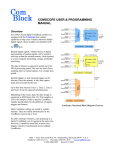
The XML1000 I/O Server is another member of the Simple Com Tools M2M appliance family. Designed to
serve as both a partner to the COM1000 and a stand-alone device, the XML1000 is also an important device
servicing the M2M market. Simplistic in both its design and feature set, the XML1000 serves a virtually unaddressed niche in the M2M market – the low-cost standardsbased, open-source, hardware appliance for capturing and
reporting digital and analog I/O events.
As its name implies, the XML1000 serves the status and
changes to its digital and analog interfaces via an XML format.
XML (Extensible Markup Language) is a simple, flexible text
format similar to HTML. Originally designed to meet the
challenges of electronic publishing and electronic data exchange
requirements, XML is now also playing an increasingly important
role in the exchange of a wide variety of data on the Web,
including Telemetry, SCADA, and M2M applications.
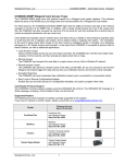
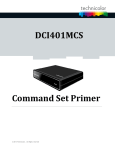
The XML1000 comes with three different interface options;
RS232, RS485, and Ethernet. This manual is dedicated to the RS232 version only.
Serial (RS232) version of XML1000
SimpleComTools, LLC
4
SimpleComTools, LLC
XML1000 – User Manual
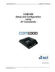
Interfaces
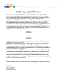
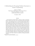
The XML1000 provides the following hardware interfaces:
•
(8) Digital Inputs
•
(8) Analog Inputs
•
(2) Relay Outputs
•
(2) Analog Outputs
•
(1) RS232 DB9 Serial Port
DIGITAL INPUT SIDE
ANALOG INPUT SIDE
Relay
Outputs
Digital
Inputs
Analog
Inputs
Analog
Outputs
Power
Input
This interface is
used to connect a
device that you want
to turn on and off.
This interface is used to
connect simple contact
closure switches.
This interface is used to
connect simple analog
measurement gauges.
This interface is
used to provide
variable 0-5vdc
analog output.
This interface is
used to connect to
a 9-30 VDC
power source.
SimpleComTools, LLC
5
SimpleComTools, LLC
XML1000 – User Manual
Connecting Sensors, Switches, or Devices
The following describes how to wire sensors, switches or controls to the XML1000 inputs.
The RELAY is designed to switch currents (120VAC/2A, 24VDC/5A). In a
sense, the RELAY can act as a contact closure or switch for any external
device. The relay connections are labeled as Normally Open (NO), Common
(COM), and Normally Closed (NC). When wiring, connect your wires to the NO
and COM if you want the switched circuit to be CLOSED when the relay is
ACTIVATED. Connect your wires to NC and COM if you want the switched
circuit to be OPEN when the relay is ACTIVATED.
The DIGITAL INPUT interfaces are designed to connect to up to either dry
contact closures or voltage pulses. The interface provides two (6) wire inputs;
(4) switch inputs and (2) grounds (GND). Switches are connected across any of
the inputs (labeled with numbers 1-8). The grounds (labeled with GND) are used
as commons, and are where you connect the second switch wire. The reasons
for only (4) commons is because you can share the GND inputs between
switches the switches. The following is a wiring example:
The ANALOG INPUT interface has the ability to interface with any analog
sensor with the following voltage output ranges: 0-5 VDC; 0-30 VDC; 4-20mA.
The following is a sensor wiring example:
The ANALOG OUTPUT interface is designed to provide a variable voltage
output of 0-5VDC.
SimpleComTools, LLC
6
SimpleComTools, LLC
XML1000 – User Manual
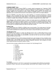
Hardware Dimensions
The XML1000 I/O Server is approximately 4.5” x 4.5” x 1” in size. Exact dimensions are as follows:
Serial Side View
Terminal Side View
Top View
SimpleComTools, LLC
7
SimpleComTools, LLC
XML1000 – User Manual
I/O Options
The XML1000 provides the following hardware interfaces:
•
(8) Digital Inputs
•
(8) Analog Inputs
•
(2) Relay Outputs
•
(2) Analog Outputs
The following describes the potential configuration options available for purchase:
Options
Digital Inputs
Relay Outputs
Analog Inputs
Analog Outputs
A
CC/0-5
(8) Contact Closure
Inputs
(2) SPDT Relays
2A at 120 VAC
5A at 24 VDC
(8) Inputs
at 0-5 VDC
(2) Outputs
at 0-5 VDC
B
CC/0-30
(8) Contact Closure
Inputs
(2) SPDT Relays
2A at 120 VAC
5A at 24 VDC
(8) Inputs
at 0-30 VDC
(2) Outputs
at 0-5 VDC
C
CC/4-20
(8) Contact Closure
Inputs
(2) SPDT Relays
2A at 120 VAC
5A at 24 VDC
(8) Inputs
at 4-20 mA
(2) Outputs
at 0-5 VDC
D
OI/0-5
(8) Optically Isolated
Inputs
(2) SPDT Relays
2A at 120 VAC
5A at 24 VDC
(8) Inputs
at 0-5 VDC
(2) Outputs
at 0-5 VDC
E
OI/0-30
(8) Optically Isolated
Inputs
(2) SPDT Relays
2A at 120 VAC
5A at 24 VDC
(8) Inputs
at 0-30 VDC
(2) Outputs
at 0-5 VDC
F
OI/4-20
(8) Optically Isolated
Inputs
(2) SPDT Relays
2A at 120 VAC
5A at 24 VDC
(8) Inputs
at 4-20 mA
(2) Outputs
at 0-5 VDC
Determining Device Type
The XML1000 provides labeling on the bottom of the device that indicates the device specifications and type.
SimpleComTools, LLC
8
SimpleComTools, LLC
XML1000 – User Manual
2
Getting Started
Before you begin
This guide is intended for qualified service personnel who are installing the XML1000 for the first time or who
need to install a switch, gauge, modem, or other device to an existing XML1000. However, before you install
anything related to the XML1000, make sure that the proper cables have been selected and/or the required
network cabling has been installed using standard cable system practices.
Installation Requirements and Instructions
Mounting:
The XML1000 has (4) slotted mounting holes and (2) oval mounting holes for easy
mounting and installation. You can use either wood or sheet metal screens, hooks, or
other common fasteners to mount or hang the device.
Power:
The XML1000 will accept 9-30VDC. For locations with 110VAC power, you will need
to provide a 100-12VDC power transformer. Tthe XML1000 The power interface is a
standard 2-wire (+ and -) terminal strip. Disconnect the 2-lead terminal strip insert
plug from the XML1000 power interface. With a power adapter or wire that is not yet
connected to a power supply, insert the positive wire into the left (+) side access hole
of the insert plug and tighten the retaining screw. Next, insert the ground wire into the
right (-) side access hole of the terminal strip and tighten the second retaining screw.
Plug the terminal strip plug into the XML1000 power interface. Finally, connect the
other end of the wire or the power supply to your power source.
Do NOT insert live power leads directly into the Analog, Digital, and Relay inputs, as
this may severely damage the XML1000. Failure to comply with this warning will void
any and all existing product warranties or service agreements.
Environment:
SimpleComTools, LLC
The XML1000 is NOT water-resistant, waterproof or weatherproof.
Installation should include an enclosure to protect electronics.
Preferably a NMEA-4 type enclosure to ensure protection from
water and humidity.
9
SimpleComTools, LLC
XML1000 – User Manual
3
Basics of Operation
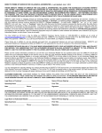
Overview
The XML1000 is a compact XML-based hardware serial I/O server. The term “I/O server” is more commonly
used with software based applications running on a PC or server. They allow you to control or monitor PLCs
or RTUs using various communication protocols, such as DNP, Modbus, etc. In contrast, the XML1000 Serial
I/O server is a hardware appliance that monitors 20
points of I/O locally, allowing you to monitor and
XML1000 Block Diagram
control the I/O using XML as the communications
protocol. The physical interface is an RS232 DB9
port, which allows for a network agnostic
communications transport. Communicating to the
XML100 can be done over serial links, leased-lines,
dialup, or via TCP/IP using IP-to-Ethernet device
servers.
Architecture
The XML1000 is architected to offer an alternative to
the traditionally complex means of communicating
with hardware I/O. It provides a plain ASCII text
based XML interface for capturing and reporting
digital and analog I/O events. To facilitate the
integration of the XML1000 with applications or
devices that do not have the ability to format or
parse XML data, the XMl1000 also supports a set of
Hayes-style AT Commands.
Integration with SCADA applications
Since the XMl1000 I/O server presents I/O data in an open format, it is easily integrated into existing SCADA,
telemetry, or meter reading applications. Applications configured to read I/O from the XML1000 can post the
data to a local or remote database, or expose the data points to industrial automation and SCADA client
applications using automation industry standard protocols, such as OPC and DDE.
SimpleComTools, LLC
10
SimpleComTools, LLC
XML1000 – User Manual
4
Basics of XML
Basics of XML
XML (Extensible Markup Language) is a simple, flexible text format similar to HTML. Originally designed to
meet the challenges of electronic publishing and electronic data exchange requirements, XML is now also
playing an increasingly important role in the exchange of a wide variety of data on the Web, including
Telemetry, SCADA, and M2M applications.
XML provides a text-based means to describe and apply a tree-based structure to information. Since XML is
based on ASCII text, an XML document may be viewed or created using any text based editor, such as
Notepad, or even word processors such as Microsoft Word. This one factor alone has facilitated the rapid
expansion of XML as a document authoring and integration tool.
Prior to the advent of XML, there were very few data description languages that were general-purpose,
Internet protocol-friendly, and very easy to learn and author. In fact, most data interchange formats were
proprietary, special-purpose, "binary" formats, based on bit sequences rather than characters. (This is a fact
that remains true for most SCADA and telemetry devices and applications). However, as processing power
and memory resources increase in the world of embedded hardware, XML will likely emerge as a preferred
way of presenting I/O status and historical data.
Benefits to using XML
Here are just a few of the benefits of using XML to manage data:
Simplicity
Information coded in XML is easy to read and understand, plus it can be processed easily by computers.
Extensibility
There is no fixed set of tags. New tags can be created as they are needed.
Open Standard
XML has quite a few benefits when it comes to deployment in M2M applications. First, XML is a standard,
simple, self-describing way of presenting data. That means the content can be processed with relatively little
development effort, and exchanged across diverse hardware, operating systems, and applications and can be
used with a wide range of development tools and utilities.
Vendor Neutrality
XML is vendor neutral, which means by using XML in communications protocols, and managing their data in
XML formats, companies can maximize the lifetime of their investment and enjoy flexibility in the choices they
will be able to make in future products and solutions.
Separation of the content from the presentation
XML tags describe meaning of the data and not the presentation. This allows the presentation of the data to
be changed without touching the original data. Making it easy to create innumerable variations of querying or
presenting the same data.
Extensive Support
There are a number of companies that have extensive support for XML, including companies such as
Software AG, IBM, Sun, Microsoft, Netscape, DataChannel, SAP and many others. In addition, both
Microsoft's and Netscape's Web browsers support XML, and Microsoft now uses XML as the data exchange
format for Microsoft Office.
SimpleComTools, LLC
11
SimpleComTools, LLC
XML1000 – User Manual
Reading an XML Document
At its base level, all information displays as readable text, interspersed with markup tags that indicate the
information's logical separation into a hierarchy. That hierarchy has container-like elements, followed by the
relevant data. In this respect, browsing through an XML document is similar to looking at the outline of a
textbook, or browsing through a PC operating system such as MS Windows.
Book Outline Example
1. Chapter 1
a. Section 1
i. Data 1
ii. Data 2
iii. Data 3
b. Section 2
i. Data 1
ii. Data 2
iii. Data 3
c. Section 3
Operating System Hierarchy Example
C:\WINDOWS\system32\drivers\etc
C:\
WINDOWS\
system32\
drivers\
etc\
XML1000 Example Output ‘Document’
<?xml version="1.0" encoding="UTF-8"?>
<XML1000>
<DIN>
<D1>1</D1>
<D2>1</D2>
<D3>1</D3>
<D4>1</D4>
<D5>1</D5>
<D6>1</D6>
<D7>1</D7>
<D8>1</D8>
</DIN>
<AOUT>
<AO1>5.0</AO1>
<AO2>3.5</AO2>
</AOUT>
<RELAY>
<R1>0</R1>
<R2>0</R2>
</RELAY>
</XML1000>
SimpleComTools, LLC
Familiar example of a data
presented in TREE format
12
SimpleComTools, LLC
XML1000 – User Manual
XML Syntax Overview
Data being returned from the XML100 is in a structured format called a ‘document’. Each XML document has
both a logical and a physical structure. Physically, the document is composed of units called entities. An entity
may be stored or dynamic data, or may refer to other entities to cause their inclusion in the document.
Documents are composed of declarations, elements, comments, character references, and processing
instructions, all of which are indicated in the document by explicit markup tags. In order to understand a
document and discern the relevant data being provided, you will need to have a detailed description of each
component of the document and instructions on how to use it. This is called a syntax description.
XML Declaration
The first line in an XML document is the XML declaration:
Example: <?xml version="1.0" encoding="UTF-8"?>
This is an optional line stating what version of XML is in use (normally version 1.0), and may also contain
information about character encoding and external dependencies. It is not often necessary, unless using XSL
(eXtensible Stylesheet Languages) to format the data. Several web-browsers including Internet Explorer,
Firefox, and Mozilla support transformation of XML to HTML. Therefore if you are using a browser to view the
data from an XML1000, you would want to use the optional XML declaration.
Elements
The remainder of the XML document consists of nested elements, some of which have other nested
elements and/or content. An element typically consists of two tags surrounding other elements or data.
These tags are called the start and end tags, or tag sets.
The start tag consists of a name surrounded by angle brackets, such as
The end tag consists of the same name surrounded by angle brackets,
but with a forward slash preceding the name, such as
"<sample tag>";
"</sample tag>".
The element's content is everything that appears between the start tag and the end tag, including other
(child) elements and actual data. When there is another set of element tags inside a tag set, the outer tag set
is referred to as the parent tag. The inner tag set that surrounds the data content are called child tags.
The following is a complete XML element, with start tag, text content, and end tag:
<ELEMENT1>Test Data</ELEMENT1>
The following samples show several XML elements, with start tags, nested elements, and data.
<START>
<PARENT1>
<NESTEDELEMENT1>Test Data</NESTEDELEMENT1>
</PARENT1>
</START>
<DATA>
<PARENT1>
<NESTEDELEMENT1>Test Data</NESTEDELEMENT1>
<NESTEDELEMENT2>Test Data</NESTEDELEMENT2>
</PARENT1>
<PARENT2>
<NESTEDELEMENT1>Test Data</NESTEDELEMENT1>
</PARENT2>
</DATA >
SimpleComTools, LLC
13
SimpleComTools, LLC
XML1000 – User Manual
Document Correctness
For an XML document to be correct, it must be both well-formed and valid. That means that the document
conforms both to the rules of XML, as well as the requirements of the schema (in this case, the correct values
required to interrogate and configure the XML1000).
It is therefore possible that documents could be well-formed but not valid. Conversely, documents could
conform to the correct schema, but may not be formatted properly (well-formed). It is essential that both
factors are present in order for XML to work properly.
Well Formed Documents
A well-formed document conforms to all of the W3C XML syntax rules.
For more info on well-formed documents, refer to the W3C website at http://www.w3.org/XML.
Below are some examples of those rules for well-formed documents:
1. The document may have only one root element.
2. Non-empty elements must have both opening and closing tags.
3. Empty elements may be marked with an empty-element (self-closing) tag, such as <EMPTY/>.
4. All attribute values are quoted, either single (') or double (") quotes.
5. Single quotes close a single quote and double quotes close a double quote.
6. Tags may be nested but must not overlap.
7. Each non-root element must be completely contained in another element.
8. Document elements match required case-sensitivity.
Example: the tag <Sample> is not the same as <SAMPLE>.
9. The document complies to its character set definition.
Valid Documents
Valid document have data that conforms to defined content rules, or XML schema.
Below are some examples of those rules for valid documents:
1. Elements must have the correct data type.
2. Elements required to contain a numeric value, may not contain text.
3. Elements required to contain a text may only not contain a numeric as part of the string.
4. Elements that are numeric, must be displayed as the correct type - integer or decimal.
SimpleComTools, LLC
14
SimpleComTools, LLC
XML1000 – User Manual
5
Communicating with the XML1000
The following section provides the basic tools needed to begin communicating with the XML1000 using XML.
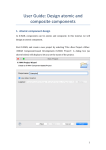
Communicating to the XML1000 Serial I/O Server
Communicating with the XMl1000 Serial I/O Server is done
thru a DB9 male connector (RS232). The port is configured
as a DTE (terminal) port with a baud rate of 115200,8N1. No
flow control is used as this is a 3 wire device (TX, RX and
GND). (All flow control signals are “Looped-Back” for your
convenience).
Therefore, in order to connect to the
XML1000 from a PC, you will need to use either a standard
serial cable and a null adapter or a null serial cable.
Connection Examples
Ethernet Network Connection
To connect an XML1000 to an Ethernet LAN, simply use a Serial Device Server such as the Digi One SP or
the Lantronix UDS-10.
COM1000 connected to a serial device server
Wireless Network Connection (802.11)
To connect an XML1000 to an Ethernet LAN, simply use a Serial Device Server such as the Digi One SP or
the Lantronix UDS-10.
COM1000 connected to a wireless serial device server
SimpleComTools, LLC
15
SimpleComTools, LLC
XML1000 – User Manual
Wireless Network Connection (Cellular)
To connect an XML1000 to an Ethernet LAN, simply use a Serial Device Server such as the Digi One SP or
the Lantronix UDS-10.
COM1000 connected to a serial cellular data modem
Configuring and Querying the device
When sending XML formatted commands to the XML1000, it is important know some basic rules:
1 – Messages send to the device are XML documents.
When you format an XML based command to configure or query the XML1000, all the rules
that pertain to document presentation apply. That means that commands must be both
well-formed and valid. If a command does not meet those rules, the XML1000 will return a
document with the <ERROR> element.
2 – Messages face parsing time limitations
XML formatted commands are processed by the XML1000 parser as a complete message.
Therefore typing an XML formatted message one character at a time will not work.
There is not way to type commands fast enough to send commands by hand.
3 – Support for short (abbreviated) notation.
XML formatted commands may be either normal or abbreviated notation.
For example – when querying the device using the ROOT element, you can send either:
<XML1000></XML1000>
or
<XML1000/>
Long Notation
Abbreviated Notation
Sample of communicating with an XML1000
using HyperTerminal over TCP/IP.
Sending the ROOT element to the device can
be done using the Copy/Paste command.
SimpleComTools, LLC
16
SimpleComTools, LLC
XML1000 – User Manual
Querying the Entire Device Configuration
As shown above, sending either <XML1000></XML1000> or <XML1000/> will query the root element. The
device will respond with all its element values, including general configuration values and live data values.
Querying Specific Values
To query a specific value, the command will have to include the root element followed by the sub element
start and ending tags. Here are some examples:
Query
Response
<?xml version="1.0" encoding="UTF-8"?>
<XML1000>
<CFG>
<UID>TEST1</UID>
<VER>XML1000 1.3.002.A</VER>
<EID>0</EID>
<XSL>1</XSL>
<RBX>1</RBX>
<RBXTMR>1</RBXTMR>
<RBXCNT>0</RBXCNT>
<AUNITS>0</AUNITS>
</CFG>
</XML1000>
Query for General Config Values
<XML1000><CFG></CFG></XML1000>
or
<XML1000><CFG/></XML1000>
<?xml version="1.0" encoding="UTF-8"?>
<XML1000>
<DIN>
<D1>1</D1>
<D2>1</D2>
<D3>1</D3>
<D4>1</D4>
<D5>1</D5>
<D6>1</D6>
<D7>1</D7>
<D8>1</D8>
</DIN>
</XML1000>
Query for Digital Input Values
<XML1000><DIN></DIN></XML1000>
or
<XML1000><DIN/></XML1000>
<?xml version="1.0" encoding="UTF-8"?>
Query for Digital Input Counts
<XML1000><DCNT></DCNT></XML1000>
or
<XML1000><DCNT/></XML1000>
SimpleComTools, LLC
17
<XML1000>
<DCNT>
<C1>000000000</C1>
<C2>000000000</C2>
<C3>000000000</C3>
<C4>000000000</C4>
<C5>000000000</C5>
<C6>000000000</C6>
<C7>000000000</C7>
<C8>000000000</C8>
</DCNT>
</XML1000>
SimpleComTools, LLC
XML1000 – User Manual
<?xml version="1.0" encoding="UTF-8"?>
<XML1000>
<AIN>
<A1>0.0</A1>
<A2>0.0</A2>
<A3>0.0</A3>
<A4>0.0</A4>
<A5>0.0</A5>
<A6>0.0</A6>
<A7>0.0</A7>
<A8>0.7</A8>
</AIN>
</XML1000>
Query for Analog Input Values
<XML1000><AIN></AIN ></XML1000>
or
<XML1000><AIN/></XML1000>
<?xml version="1.0" encoding="UTF-8"?>
Query for Relay Status
<XML1000><RELAY ></RELAY></XML1000>
or
<XML1000><RELAY/></XML1000>
<XML1000>
<RELAY>
<R1>0</R1>
<R2>0</R2>
</RELAY>
</XML1000>
Error Messages
As mentioned earlier, when an invalid message is sent to the XML1000, the device will return an <ERROR>
element, along with the child element describing the type of effort and the offending data if present. The
following described the (5) types of errors:
<BADFORMAT>
This will usually happen if the 5 second inter-character timeout happens and there is garbage in buffer.
<READONLY>
This occurs when attempting to WRITE data to a READ ONLY element.
<DATATYPE>
This occurs when attempting to WRITE an invalid value to any element. (Ex: writing ABC to analog output)
<OUTOFRANGE>
This occurs when attempting to WRITE an unsupported value to any element. (Ex: writing a 2 to relay output).
<SYNTAX>
General error response
XML1000 Element Naming Convention Descriptions
The chosen names for XML elements are what convey the meaning of data in the markup document. This
increases human readability while retaining the structure for parsing. The goal is to choose names that imply
the meaning of the elements and data to a human reader without requiring a reference manual. However,
because being too descriptive can lead to verbose element names (and thus have an impact of processing
power and use of network bandwidth), it may be necessary to have tags that are abbreviated.
Having tags that accomplish the goal of readership without being too verbose is the ideal goal. The XML1000
element names were designed for just that reason. While they may seem a little bit cryptic at first, their
meanings becoming quite clear once they are defined. The following table details each tag and its relationship
to the parent element.
SimpleComTools, LLC
18
SimpleComTools, LLC
XML1000 – User Manual
TAG
DESCRIPTION
DATA TYPE
PARENT
XML1000
Root element
N/A
None
CFG
Parent for CFG elements
N/A
XML1000
UID
Unique Device ID
string
CFG
VER
Firmware Version
string
CFG
EID
Include UID in data responses and RBX
integer
CFG
XSL
Include XML declaration in output
integer
CFG
RBX
Report By Exception feature
integer
CFG
RBXTMR
Time between RBX reports
integer
CFG
RBXCNT
Time between RBX reports
integer
CFG
AUNITS
Sets analog to be volts or decimal
integer
CFG
DIN
Parent for Digital Inputs
N/A
XML1000
Dn
Analog Output values
integer
DIN
DTYPE
Parent for Digital Input Types
N/A
XML1000
Tn
Sets Digital Inputs to NO or NC
integer
DTYPE
DCNT
Parent for Digital Input Counts
N/A
XML1000
Cn
Digital Input counts
integer
DCNT
AIN
Parent for Analog Inputs
N/A
XML1000
An
Analog Input values
decimal
AIN
AMINVAL
Parent for Analog Input Min Values
N/A
XML1000
AnMN
Lowest value since last request
decimal
AMINVAL
AMAXVAL
Parent for Digital Input elements
N/A
XML1000
AnMX
Highest value since last request
decimal
AMAXVAL
AMINSETPT
Parent for Digital Input elements
N/A
XML1000
AnMNSP
Low setpoints for RBX reporting
decimal
AMINSETPT
AMAXSETPT
Parent for Digital Input elements
N/A
XML1000
AnMXSP
High setpoints for RBX reporting
decimal
AMAXSETPT
AOUT
Parent for Digital Input elements
N/A
XML1000
AOn
Analog Output values
decimal
AOUT
RELAY
Parent for Relay Outputs
N/A
XML1000
Rn
Relay Output values
decimal
RELAY
SimpleComTools, LLC
19
SimpleComTools, LLC
XML1000 – User Manual
XML1000 Example Output ‘Document’
<?xml version="1.0" encoding="UTF-8"?>
<XML1000>
<ID>TEST1</ID>
<CFG>
<UID>TEST1</UI
<VER>XML1000 1.3.002.A</VER>
<EID>1</EID>
<XSL>1</XSL>
<RBX>1</RBX>
<RBXTMR>1</RBXTMR>
<RBXCNT>0</RBXCNT>
<AUNITS>0</AUNITS>
</CFG>
<DIN>
<D1>1</D1>
<D2>1</D2>
<D3>1</D3>
<D4>1</D4>
<D5>1</D5>
<D6>1</D6>
<D7>1</D7>
<D8>1</D8>
</DIN>
<DCNT>
<C1>000000001</C1>
<C2>000000001</C2>
<C3>000000001</C3>
<C4>000000001</C4>
<C5>000000001</C5>
<C6>000000001</C6>
<C7>000000001</C7>
<C8>00000000
</DCNT>
<AIN>
<A1>0.0</A1>
<A2>0.0</A2>
<A3>0.0</A3>
<A4>0.0</A4>
<A5>0.0</A5>
<A6>0.0</A6>
<A7>0.0</A7>
<A8>0.7</A8>
</AIN>
<AOUT>
<AO1>5.0</AO1>
<AO2>3.5</AO2>
</AOUT>
<RELAY>
<R1>0</R1>
<R2>0</R2>
</RELAY>
</XML1000>
SimpleComTools, LLC
20
SimpleComTools, LLC
XML1000 – User Manual
XML1000 Example Output ‘Document’
<?xml version="1.0" encoding="UTF-8"?>
<XML1000>
<UID>TEST1</UID>
<CFG>
<UID>TEST1</UI
<VER>XML1000 1.3.002.A</VER>
<EID>1</EID>
<XSL>1</XSL>
<RBX>1</RBX>
<RBXTMR>1</RBXTMR>
<RBXCNT>0</RBXCNT>
<AUNITS>0</AUNITS>
</CFG>
<DIN>
<D1>1</D1>
<D2>1</D2>
<D3>1</D3>
<D4>1</D4>
<D5>1</D5>
<D6>1</D6>
<D7>1</D7>
<D8>1</D8>
</DIN>
<DCNT>
<C1>000000001</C1>
<C2>000000001</C2>
<C3>000000001</C3>
<C4>000000001</C4>
<C5>000000001</C5>
<C6>000000001</C6>
<C7>000000001</C7>
<C8>00000000
</DCNT>
<AIN>
<A1>0.0</A1>
<A2>0.0</A2>
<A3>0.0</A3>
<A4>0.0</A4>
<A5>0.0</A5>
<A6>0.0</A6>
<A7>0.0</A7>
<A8>0.7</A8>
</AIN>
<AOUT>
<AO1>5.0</AO1>
<AO2>3.5</AO2>
</AOUT>
<RELAY>
<R1>0</R1>
<R2>0</R2>
</RELAY>
</XML1000>
SimpleComTools, LLC
21
•
•
•
•
•
•
<XML1000> is the ROOT (top hierarchal) element
Main ‘container’ for all other elements & data
Equivalent to the MAIN C:\ drive of your PC
Each lower data element is wrapped in a container
Equivalent to a folder or sub-directory on your PC
Data array is wrapped with a start and closing tag
•
•
General configuration values (CFG)
Includes UID, VER, EID, XSL, RBX and more
•
•
Digital input STATUS data
<DIN><D1>data</D1></DIN>
•
•
•
•
Digital input COUNT data
DCNT is the ‘parent’ container
Each COUNT has it’s own container as well
<DCNT><C1>data</C1></DCNT>
•
•
Analog input STATUS
<AIN><A1>data</A1></AIN>
•
•
Analog output STATUS
<AOUT><AO1>data</AO1></AOUT>
•
•
Relay output STATUS
<RELAY><R1>data</R1></RELAY>
•
‘</XML1000>’ is the closing tag for the ‘document’
SimpleComTools, LLC
XML1000 – User Manual
6
Using the
xml1000 Configuration Utility
The XML1000 Configuration Utility is provides a desktop style GUI to allow you to read and configure the
XML1000 using simple select boxes and buttons. The utility is also designed to present the end user or
developer with the ability to see the actual XML code being sent to and received from the device in real time.
Configuration Utility
Layout
The utility is broken down into various sections and functional blocks. The layout and explanation of the
functions is as follows:
• CONNECTION
Enables connection to the device over Com Port or TCP/IP connection.
• GENERAL
Displays and sets Unit ID value and displays current firmware version.
• DEVICE CONFIGURATION
Displays and configures global display and reporting behaviors.
• DIGITAL INPUTS
Displays Digital Input states.
• DIGITAL COUNTS
Displays and sets Digital Input counts.
• ANALOG INPUTS
Displays and sets Analog Input values.
• RELAY OUTPUTS
Displays and sets Relay Output states.
• ANALOG OUTPUTS Displays and sets Analog Output values.
• SENT
Displays the XML code most recently sent to the device.
• RECEIVED
Displays the XML code most recently received from the device.
Configuration Utility Connection Steps
Step 1:
Connect your PC to the XML1000 RS232 interface using a standard RS232 cable and null adapter or a null
RS232 cable. The XML1000 interface is a DTE port, so a standard serial cable alone will not work.
Step 2:
Launch the XML1000 Configuration Utility. Select the correct COM Port on your PC from the Connection
Type drop down menu and click on CONNECT. You will be able to view the status of the connection in the
Status window.
Step 3:
Once you have successfully gained access to the device, you can view or edit any of the XML1000
application registers. To view ALL the current register settings, click on the Get All Parameters button.
SimpleComTools, LLC
22
SimpleComTools, LLC
XML1000 – User Manual
Select your communications method
Clink on Get All Parameters to read device
Take note of the ‘Sent’ section.
When you select Get All
Parameters, you will see what is
being sent to the device. In this
case, the application sends
<XML1000/> - which is XML
short notation for the command
<XML1000></XMl1000>
SimpleComTools, LLC
23
SimpleComTools, LLC
XML1000 – User Manual
Take note of the values
located on the status tab.
Take note of the values
located on the tab.
Take note of the
‘Received’ section.
This tab displays COM
setting as well as the number
of bytes sent and received.
These values will be
populated when the values
are returned from the device.
This will show you the
exact XML data returned
from the device.
Selecting TCP/IP will
allow you to connect to
the device over IP.
Enter the IP address and
port into the appropriate
boxes and select
CONNECT.
SimpleComTools, LLC
24
SimpleComTools, LLC
XML1000 – User Manual
Reading and making changes to the device
Reading any individual value is done by using the Get
button. Changes can be made by using either the dropdown menu or entering the desired value in the text box
and hitting the Set button.
All changes are immediately written to the device.
There is no need to ‘save’ any set changes.
Clearing existing values
In the case of numeric values, clearing is simply done by
entering a zero. In the case of text values, clicking on the
Set button with an empty text field will clear the value from
the device.
Making manual changes to commands being sent to the device
While it is possible to change what commands are being sent to the device using the provided Get and Set
buttons, the utility also provides you the ability to manually edit the SENT commands inside the Sent window.
This allows you to test
your understanding of
XML
syntax.
Simply
change the command
being sent to what you
would like to test, and
then click on the Send
button.
What you see in the Sent
window will now be sent
to the device. The new
response will appear in
the refreshed Received
window.
Saving the settings as a template
The XML1000 configuration utility has a TEMPLATE function. This
feature is designed to provide the ability to save a device
configuration for future use or application to another device. Here
are the basic options:
Saving a configuration
Select the File/Save and give the file a name and save it with
either a .txt or .xml extension.
Reading a configuration
Select File/Open and select the configuration file you want to use. When opened, the settings will populate.
Edit values if appropriate, and click on any individual Set button or the Set button next to the
ALL heading.
SimpleComTools, LLC
25
SimpleComTools, LLC
XML1000 – User Manual
6
Using ‘AT’ Commands
As mentioned earlier, the XML1000 AT Commands are a format similar to traditional Hayes-Compatible AT
Commands, but because the device is not a modem, the similarities are modest. In order to configure the
device using AT Commands, follow these directions:
Connection Steps
Step 1:
Connect your PC to the XML1000 RS232 interface using a
standard RS232 cable and null adapter or a null RS232 cable.
The XML1000 interface is a DTE port, so a standard serial
cable alone will not work.
Step 2:
Open a connection using any Terminal program, such as
HyperTerminal or TeraTerm. The default setup for the port is
1152000, 8, None, and 1
Step 3:
Once connected, enter ‘AT’ and hit the RETURN or ENTER key. You should ‘OK’ as the response.
To view ALL the current register settings, enter AT&V.
Step 4:
Once you have successfully gained access to the command prompt, you can view or edit any
of the XML1000 application registers. The following pages detail the available commands.
SimpleComTools, LLC
26
SimpleComTools, LLC
XML1000 – User Manual
Configuration Using AT Commands
The XML1000 Serial I/O Server supports two communications protocols: XML and AT Commands.
The following is a list of the AT Commands listed by category:
Basic Device Configuration Parameters
AT Command
Description
Description: Returns state of all device registers.
&V
Query
AT&V
Returns entire device configuration showing all registers.
Description: Analog Input Units; sets values to be either raw voltage or decimal
Query
AT*AUNITS
AUNITS
Configuration
AT*AUNITS=n
Options:
0 = Raw Voltage Value (Default)
1 = Decimal Value (0-1023)
Description: Choose to include the UID in every report and response.
Query
AT*EID
EID
Configuration
AT*EID=n
Options:
0 = Disabled (Default)
1 = Enabled
Description: Report By Exception; enables automatic reporting of changes in
I/O or passing analog set point thresholds.
Query
AT*RBX
RBX
SimpleComTools, LLC
Configuration
AT*RBX=n
Options:
0 = Disabled (Default)
1 = Report only the specific INPUT value that has changed
2 = Report the entire GROUP when any of the group changes
3 = Report the entire DEVICE when any inputs has changed
27
SimpleComTools, LLC
XML1000 – User Manual
Description: Report By Exception number; # of repeat RBX reports.
Query
AT*RBXNUM
RBXNUM
Configuration
AT*RBXNUM=n
Options:
n = (0 –Never Reports)
n = (1 – 255)
Description: Report By Exception timer. Time between RBX reports (in MIN).
Query
AT*RBXTMR
RBXTMR
Configuration
AT*RBXTMR=n
Options:
n = (0 - 255)
Note:
Setting the value to 0 means RBX will never repeat.
Description: Reads or sets the Unique Device ID (UID).
UID
Query
AT*UID
Configuration
AT*UID=xxxxx
Options:
x = Up to 32 alphanumeric characters.
Description: Current Firmware Version.
VER
Query
AT*VER
Returns current XML1000 firmware version.
Description: XSL Header setting. Enables/disables the XML header for
facilitating the presentation of XML data in an XML tree format when using a
browser.
XSL
Query
AT*XSL
Configuration
AT*XSL=n
Options:
0 = Disabled (Default)
1 = Enabled
SimpleComTools, LLC
28
SimpleComTools, LLC
XML1000 – User Manual
Analog Inputs
AT Command
Description
Description: Analog Input Status.
An
Query
AT*An
Query the state of any Analog Input.
Options:
n = (1 – 8)
Response value is contingent upon the status of the AUNITS register.
(0.00 – 5.00) for units with 0-5VDC inputs when AUNITS=0
(0.00 – 30.00) for units with 0-30VDC inputs when AUNITS=0
(0.00 – 16.00) for units with 4-20mA inputs when AUNITS=0
(0 – 1023) when AUNITS=1
Description: Analog Input Minimum
LOWEST value attained since the last read request.
Query
AT*AnMN
Query the LOWEST attained value for the analog input.
Response value will be in either VOLTAGE or DECIMAL format, whichever one
is selected in the AUNITS register.
Options:
n = (1 – 8)
AnMN
Response value is contingent upon the status of the AUNITS register.
(0.00 – 5.00) for units with 0-5VDC inputs when AUNITS=0
(0.00 – 30.00) for units with 0-30VDC inputs when AUNITS=0
(0.00 – 20.00) for units with 4-20mA inputs when AUNITS=0
(0 – 1023) when AUNITS=1
Configuration
AT*AnMN=y
Command to reset the LOWEST reached value for the analog input.
New value must be in the same format selected in the AUNITS register.
Options:
n = (1 – 8)
y = (0.00 – 5.00) for units with 0-5VDC inputs when AUNITS=0
y = (0.00 – 30.00) for units with 0-30VDC inputs when AUNITS=0
y = (4.00 – 20.00) for units with 4-20mA inputs when AUNITS=0
y = (0 – 1023) when AUNITS=1
SimpleComTools, LLC
29
SimpleComTools, LLC
XML1000 – User Manual
Description: Analog Input Minimum Setpoint.
The LOW setpoint for exception reporting.
Query
AT*AnMNSP
Query the MINIMUM (LOW) SETPOINT of the analog input.
Response value will be in either VOLTAGE or DECIMAL format, whichever one
is selected in the AUNITS register.
Options:
n = (1 – 8)
AnMNSP
Response value is contingent upon the status of the AUNITS register.
(0.00 – 5.00) for units with 0-5VDC inputs when AUNITS=0
(0.00 – 30.00) for units with 0-30VDC inputs when AUNITS=0
(0.00 – 20.00) for units with 4-20mA inputs when AUNITS=0
(0 – 1023) when AUNITS=1
Configuration
AT*AnMNSP=y
Command to set the MINIMUM (LOW) SETPOINT for the analog input.
New value must be in the same format selected in the AUNITS register.
Options:
n = (1 – 8)
y = (0.00 – 5.00) for units with 0-5VDC inputs when AUNITS=0
y = (0.00 – 30.00) for units with 0-30VDC inputs when AUNITS=0
y = (4.00 – 20.00) for units with 4-20mA inputs when AUNITS=0
y = (0 – 1023) when AUNITS=1
Description: Analog Input Maximum
HIGHEST value attained since the last read request.
Query
AT*AnMX
Query the HIGHEST attained value for the analog input.
Response value will be in either VOLTAGE or DECIMAL format, whichever one
is selected in the AUNITS register.
Options:
n = (1 – 8)
AnMX
Response value is contingent upon the status of the AUNITS register.
(0.00 – 5.00) for units with 0-5VDC inputs when AUNITS=0
(0.00 – 30.00) for units with 0-30VDC inputs when AUNITS=0
(0.00 – 20.00) for units with 4-20mA inputs when AUNITS=0
(0 – 1023) when AUNITS=1
Configuration
AT*AnMX=y
Command to reset the HIGHEST reached value for the analog input.
New value must be in the same format selected in the AUNITS register.
Options:
n = (1 – 8)
y = (0.00 – 5.00) for units with 0-5VDC inputs when AUNITS=0
y = (0.00 – 30.00) for units with 0-30VDC inputs when AUNITS=0
y = (4.00 – 20.00) for units with 4-20mA inputs when AUNITS=0
y = (0 – 1023) when AUNITS=1
SimpleComTools, LLC
30
SimpleComTools, LLC
XML1000 – User Manual
Description: Analog Input Maximum Setpoint.
The HIGH setpoint for exception reporting.
Query
AT*AnMXSP
Query the MINIMUM (LOW) SETPOINT of the analog input.
Response value will be in either VOLTAGE or DECIMAL format, whichever one
is selected in the AUNITS register.
Options:
n = (1 – 8)
AnMXSP
Response value is contingent upon the status of the AUNITS register.
(0.00 – 5.00) for units with 0-5VDC inputs when AUNITS=0
(0.00 – 30.00) for units with 0-30VDC inputs when AUNITS=0
(0.00 – 20.00) for units with 4-20mA inputs when AUNITS=0
(0 – 1023) when AUNITS=1
Configuration
AT*AnMNSP=y
Command to set the MAXIMUM (HIGH) SETPOINT for the analog input.
New value must be in the same format selected in the AUNITS register.
Options:
n = (1 – 8)
y = (0.00 – 5.00) for units with 0-5VDC inputs when AUNITS=0
y = (0.00 – 30.00) for units with 0-30VDC inputs when AUNITS=0
y = (4.00 – 20.00) for units with 4-20mA inputs when AUNITS=0
y = (0 – 1023) when AUNITS=1
Digital Inputs (States)
AT Command
Description
Description: Digital Input TYPE. Adjusts the value of the input between
Normally Open and Normally Closed.
Query
AT*Tn
Query the state of a Digital Input.
Options:
n = (1 - 8)
Tn
Configuration
AT*Tn=y
Options:
n = (1 – 8)
y = (0 or 1)
y = 0 (Normally Open)
y = 1 (Normally Closed)
Description: Current state of the Digital Input. Response value will indicate the
state of the switch displayed as a 0 or 1.
Dn
SimpleComTools, LLC
Query
AT*Dn
Query the state of a Digital Input.
Options:
n = (1 – 8)
31
SimpleComTools, LLC
XML1000 – User Manual
Digital Inputs (Counts)
AT Command
Description
Description: Digital Input Counts. Response value will be a 9 digit value
between 0 and 999999999.
Query
AT*Cn
Query the accumulated COUNT value of a Digital Input.
Options:
n = (1 – 8)
Cn
Configuration (Reset)
AT*Cn=y
Command to reset the COUNT value of a Digital Input. Option is given to set the
counter to any value between 0 and 999999999.
Options:
n = (1 – 8)
y = (0 – 999999999) Sets the counter any desired value
Relay Outputs
AT Command
Description
Description: Relay Output state. Response value displayed as a 0 or 1.
Query
AT*Rn
Query the state of the Relay Output.
Options:
n = (1 – 8)
Rn
SimpleComTools, LLC
Configuration
AT*Rn=y
Changes the state of the Relay Output.
Options:
n = (1 or 2)
y = (0 or 1)
y = 0 (De-energized)
y = 1 (Energized)
32
SimpleComTools, LLC
XML1000 – User Manual
Analog Outputs
AT Command
Description
Description: Analog Output value.
Query
AT*A0n
Query the state of an Analog Output.
Options:
n = (1 or 2)
AOn
Response value is contingent upon the status of the AUNITS register.
(0.00 – 5.00) for units with 0-5VDC inputs when AUNITS=0
(0.00 – 30.00) for units with 0-30VDC inputs when AUNITS=0
(0.00 – 20.00) for units with 4-20mA inputs when AUNITS=0
(0 – 1023) when AUNITS=1
Configuration (Output Send)
AT*A0n=y
Command to set the voltage OUTPUT for an Analog output.
Options:
n = (1 or 2)
y = (0.00 – 5.00) for units with 0-5VDC inputs when AUNITS=0
y = (0.00 – 30.00) for units with 0-30VDC inputs when AUNITS=0
y = (4.00 – 20.00) for units with 4-20mA inputs when AUNITS=0
y = (0 – 1023) when AUNITS=1
SimpleComTools, LLC
33