1
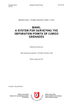
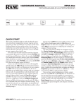
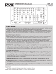
OPERATORS MANUAL
SRM 66
SPLITTER ROUTER MIXER
Out[x]:[y] IN1 IN2 IN3 IN4
Copy
+6 -3 +6 Off
IN5 IN6 MST LIM
+6 -25 +0 Max
QUICK START
Before complaining about having to install the SRM 66 in the rack twice (because you forgot to set the internal
highpass filters ahead of time), take note that the very first (non-joke) line in this manual is: Before installing the SRM 66
in a rack, be sure the internally switchable 80 Hertz highpass filters are set as desired. They are shipped with the filters in
the OUT (disabled) position. (See the bottom of page Manual-2 to enable these filters.) If you were smart enough to read
this much of the manual, this paragraph may already have saved you a few minutes of your life – you’re welcome. If
you’ve learned the hard way, hopefully you’ve learned an important lesson – read at least the first line in the manual first.
Make all connections with the power and amplifiers off. The SRM 66 is fully balanced and equipped with removable 5position Euroblock connectors. Inputs and Outputs are arranged on Euroblocks in pairs, i.e., 1&2, 3&4, 5&6.
Be sure the FP LOCK switch (on rear) is in the out position to enable programming from the front panel.
Apply power so the PWR LED lights and LCD screen glows with the SRM 66 welcome marquee. During initialization,
the startup muting circuit immediately starts counting down from 40 in the Limiter Gain Reduction area of the display.
Adjust the VIEWING ANGLE with a miniature screwdriver if necessary.
With signal applied to the Inputs, watch the MIX INPUT HEADROOM indicators. These verify correct setting of the
Output of the previous device and the rear panel Input GAIN switches. Adjust so that 4 dB lights during peaks.
Navigating the LCD Edit pages is simple. The top buttons marked << and >> are the left/right Page scroll buttons.
These navigate to Output pages 1 through 6, the assign Outputs to Output Group page, the assign Remote to Group page,
the assign Group to Master Remote page, the Group Levels page, and the Memory page.
The bottom buttons marked < and > are the left/right cursor buttons. These select the (underlined) parameter to edit.
Rotating the DATA knob changes the parameter setting.
Let’s start by navigating to Output 1’s page. Move the cursor under IN1. With a signal driving Input 1 and a working
amplifier connected to Output 1, adjust the DATA knob to the desired level. Adjust any other Input going to Output 1. MST
controls the Master level of Output 1. LIM sets the Limit Threshold of the Limiter circuit for Output 1.
To Copy settings from Output 1 to any other Output, move the cursor to Copy. Press the EXE button. The display now
reads Paste. Change the page to the one you want these same settings in, and press EXE again. The settings have now
been pasted into the new Output.
Settings may be Stored and Recalled in the Memory Page. To Store, select the Store field, select a Memory number
with the DATA wheel and press EXE. To Recall, select the Recall field, select a Memory number with the DATA wheel
and press EXE. Look deeper into this manual for information on remote control of Memories, level adjustments and, the
most powerful feature of the SRM 66, Output Groups which “link” Output levels. A Master Remote feature allows controlling the level of any Output Groups assigned to it.
To maintain signal control over the specified dynamic range, the Master output should be turned off when no inputs are
routed to a given output.
CAUTION: Never connect anything except an approved Rane Power Supply to the thing that looks like a red telephone jack on the rear of the SRM 66. This is an 18 VAC center tapped power input. Consult the Rane factory for a
replacement or substitute.
SRM 66 CONNECTION
Balanced Operation
Connect the ‘+’ to ‘+’, ‘–’ to ‘–’, and shield to shield. Use
only when driving from a true balanced source and driving to
a true balanced destination — either transformer coupled or
active drive.
uses two conductors plus a shield; connect ‘+’ to ‘+’, the
unbalanced source ground to ‘–’, and the cable shield to the
SRM 66’s ground.
Going to an unbalanced device using a single conductor
plus a shield, connect ‘+’ to ‘+’, leave ‘–’ unconnected and
connect the cable shields at both ends to ground.
Unbalanced Operation
To avoid nasty side effects such as hum and noise – which
are consequences of unbalanced operation – keep cable
lengths as short as possible. For lengths longer than ten feet,
use a transformer such as a Rane BB 44x.
Coming from an unbalanced source, the SRM 66’s Input
Combination Operation
For combined balanced and unbalanced operation, use
whichever half of the above instructions apply for each end.
See the “Sound System Interconnection” RaneNote included
with this manual for more information on cabling and
grounding requirements.
WEAR PARTS: This product contains no wear parts.
Manual-1
FRONT PANEL DESCRIPTION
Out[x]:[y] IN1 IN2 IN3 IN4
Copy
+6 -3 +6 Off
IN5 IN6 MST LIM
+6 -25 +0 Max
� MIX INPUT HEADROOM meters. These assist setting of the rear panel GAIN switches as well as the output level of the
preceding device. The 16 dB and 4 dB LEDs indicate the remaining headroom for each of the six Inputs. Optimal settings
allow the 4 dB LEDs to flash only during signal peaks.
� Edit Pages. This 2x40 backlit LCD screen displays the Edit pages for controlling and revealing all the functions of the SRM
66 (see �). Refer to the OPERATION section on page Manual-4 for details.
� VIEWING ANGLE adjust. This recessed adjustment allows optimizing the LCD display contrast for various vertical
viewing angles.
� DATA wheel. Allows adjustment of a field parameter after it is selected with the Page (see �) and Cursor (see �) buttons.
Turning the DATA wheel clockwise increases the parameter, and turning it counterclockwise decreases the parameter.
� Page buttons. The Previous Page << and Next Page >> buttons scroll through all 10 Edit pages. When the EXE button is
held and MAX >> is pressed, the selected parameter jumps to its highest value (see �).
� Cursor buttons. The Previous < and Next > cursor buttons scroll through each of the adjustable fields on each page. These
buttons select each adjustable parameter along the bottom row by moving the underline left < or right >. When any parameter is selected, the DATA wheel adjusts that parameter. When the EXE button is held and MIN > is pressed, the selected
parameter jumps to its lowest value (see �).
� EXE (Execute) button. Several commands are implemented with this button. Holding down EXE while pressing MAX >>
alters the selected parameter to its highest nominal value. Holding down EXE while pressing MIN > alters the selected
parameter to its lowest value or Off. Pressing EXE when the Copy, Paste, Recall, Store, and Zero commands are
selected executes that function.
� Power indicator. In case the backlit Edit display isn’t enough assurance, this yellow indicator glows anytime adequate
power is applied to the SRM 66, alerting you to its on condition.
INTERNAL 80 Hz HIGHPASS FILTERS
Each Output of the SRM 66 features an internally switchable 80 Hz highpass filter. These filters roll off low frequencies. This is useful in small sound reinforcement systems or for use with constant voltage line transformers. These switches
are shipped from the factory in the OUT position. If you wish to enable any or all of the filters for each Output, it will be
necessary to remove the unit’s top cover before installation. Locate the switches near the center of the board, as shown
below. S2 = Output 1, S4 = Output 2, S6 = Output 3, S8 = Output 4, S10 = Output 5, and S12 = Output 6.
Manual-2
REAR PANEL DESCRIPTION
� POWER input connector. Use only an RS 1, or other Remote AC power supply approved by Rane. This unit is supplied
with a remote power supply suitable for connection to this input jack. Consult the factory for a replacement or a substitute.
This unit’s power input is designed for an AC supply, delivering 18 volts, from a center-tapped transformer capable of
supplying at least the 750 mA of current demanded by this product. Using any other type of supply may damage the unit and
void the warranty.
�ÿ Chassis ground point. A #6-32 screw is supplied for chassis grounding purposes. Units with external power supplies such
as this SRM 66 supply do not ground the chassis to earth through the line cord. This chassis connection is critical and in
most installations, required by law. Many chassis ground this point to an amplifier chassis ground or directly to the grounding screw on a grounded AC outlet cover by means of a wire secured on both ends with star washers to guarantee proper
contact. See the CHASSIS GROUNDING note below.
� FP LOCK button. When pressed in, locks out all front panel control except for Group Levels and Memory Recall. The
SR 1L remotes (sold separately) are also able to control Group Levels with FP LOCK engaged. The user is able to view, but
not edit, all Edit pages.
� MEMORY RECALL PORT (MRP). This Port allows any remote switch to recall any of the system Memories. The first
eight Memories recall with simple switch closure to a single pin. A “binary” wiring mode allows access to more complex
Memory recall functions. See Figure 8 on page Manual-6. Complete programmability of the MRP is possible using the Edit
MRP Configuration feature found in SRM Exchange software. See DSC 1 & SRM Exchange software on page Manual-7.
� REMOTE INTERFACE PORT (RIP). This Port supports up to seven optional SR 1L “Smart” digital Remote controls as
seen in Figure 4 on page Manual-5. Each Remote may be assigned to adjust the Level of any one of the six SRM 66 Output
Groups or the Master Group.
� OUTPUT GAIN switches. These assist setting the optimal gain structure of the Output stage, depending on what the
following device would like to see (or hear). Balanced signals usually require a +4 dBu setting (button out), and unbalanced
signals usually require the -10 dBV setting (button in).
� OUTPUTS. These balanced Euroblock connectors may be wired balanced or unbalanced. See page Manual-1 or RaneNote
110, “Sound System Interconnection” later in this manual for assistance.
� INPUT GAIN switches. These assist setting the optimal gain structure of the Input stage, depending on the level from the
previous device. Balanced signals usually require a +4 dBu setting (button out), and unbalanced signals usually require the 10 dBV setting (button in). Use the MIX INPUT HEADROOM meters as a guide for determining GAIN switch position (see
� in the Front Panel Description).
� INPUTS. These balanced Euroblock connectors may be wired balanced or unbalanced. See page Manual-1 or RaneNote
110, “Sound System Interconnection” elsewhere in this manual for assistance.
CHASSIS GROUNDING
If after hooking up your system it exhibits excessive hum or buzzing, there is an incompatibility in the grounding inside
a unit(s) or between units somewhere. Your mission is to discover how your particular system wants to be grounded. Try
these things:
1. Try combinations of lifting grounds on units that are supplied with ground lift switches or links. Other than in your own
home, it is illegal and unsafe to use 2-prong to 3-prong AC line cord cheaters, even though this is a common (short term)
remedy. Using such “cheaters” can (and has been known to) electrocute or kill people. [Ace Frehley and Keith Richards
survived; Keith Relf (The Yardbirds) and John Rostill (The Shadows) did not.]
2. If your equipment is in a rack, verify that all chassis are tied to a good earth ground, either through the AC line cord
grounding pin (3rd prong) or the rack screws to another grounded chassis.
3. Units with outboard power supplies may not ground the chassis through the line cord. Make sure that these units are
grounded either to another chassis which is earth grounded, or directly to the grounding screw on a grounded AC outlet
cover.
Please refer to RaneNote 110 “Sound System Interconnection” (elsewhere in this manual) for further information.
Manual-3
OPERATION
The User Interface
All SRM 66 programming is done with the Data wheel
and the front panel buttons using one of the eleven LCD
pages. Each page consists of the page name, multiple parameter fields and possible Command fields and status indicators.
To navigate between pages use the Next Page (>>) and
Previous Page (<<) buttons. Within a page the Next (>) and
Previous (<) buttons move the cursor to each field.
Above each parameter field is a label indicating its
function. Once the cursor is positioned beneath the desired
parameter field, the Data wheel is turned clockwise to
increase the value and counter-clockwise to decrease it. To
quickly jump to extreme maximum or minimum values, hold
down the Shift (EXE) Button and press either the MAX (>>)
or MIN (>) buttons. For added safety, executing MAX for the
Input mix levels sets the level to unity or zero gain, not +6 dB
which is the actual maximum.
Command Fields
Most pages contain a Command field. Here you can Copy
settings from the current page to the clipboard, Paste settings
from the clipboard, Recall page settings from memory, and
Zero all page settings.
To access a command, position the cursor under the
Command field, use the Data wheel to select the desired
command (not all commands are available in all pages) and
press the EXE button.
Clipboard
There are actually three separate clipboards in the SRM
66: one for an Output’s settings (shared by all Outputs), one
for the Remote to Group settings, and one for the Output to
Group settings. Using the clipboard can greatly simplify and
speed setting up multiple Outputs or multiple Memories. The
clipboard settings are lost whenever power is removed.
Status Indicators
Next to the page name in many pages is a Status Indicator.
In the Output pages it shows the current amount of Limiter
gain reduction or startup muting. If there is no gain reduction
being applied, the field is blank. On the Memory page an
asterisk (*) appears in this field whenever the current working
Memory does not match the last recalled Memory.
Programming the SRM 66
Programming each SRM 66 Output requires only one edit
page as in Figure 1. Note that unique Input mix levels are
possible for each Output. All adjustments are in 1 dB steps.
The following parameters define each Output:
IN1 Input one mix Level +6 dB to -25 dB, Off
IN2 Input two mix Level +6 dB to -25 dB, Off
IN3 Input three mix Level +6 dB to -25 dB, Off
IN4 Input four mix Level +6 dB to -25 dB, Off
IN5 Input five mix Level +6 dB to -25 dB, Off
IN6 Input six mix Level +6 dB to -25 dB, Off
MST Master mix Level +0 dB to -59 dB, Off
LIM Limit Threshold Max (0 dB) to -28 dB re: clip point.
Manual-4
Output
Page,
where [x]
indicates
the Output
currently
being
edited.
Limiter gain reduction is
indicated in [y]dB when
the Limiter is active.
Sets the Master
Level reduction for
Output[x]. Range is
0 dB to -59 dB and
Off.
Sets the Input Level of Inputs 1-6
mixed at the Output. Range is +6
dB to -25 dB and Off.
Out[x]:[y] IN1 IN2 IN3 IN4
Copy
+6 -3 +6 Off
Sets the
Limiter
Threshold
for Output
[x].
IN5 IN6 MST LIM
+6 -25 +0 Max
Copy parameters of current page to clipboard.
Paste contents of clipboard to current page.
Recall[n] loads current page parameters from
Memory[n], where [n]=Memory 1-24.
Figure 1. Output Edit Page
Output Groups
The SRM 66 uses Output Groups to link the attenuation
level and Limiter gain reduction of one or more Outputs. Any
one of the seven possible SR 1L remote controls can then be
assigned to control an Output Group Level. The SRM 66 can
also assign any number of the six possible Output Groups to a
Master Group. Any number of the seven possible SR 1L
Remotes can then be assigned to control the Master Group
Level. Understanding and utilizing the power of Groups is
essential to harness the power and versatility of the SRM 66.
The Output to Group Assign page is shown in Figure 2.
Outputs can be assigned to 1 of 6 Output Groups or no Group
(off). For example, a stereo Output pair would typically be
assigned to the same Output Group in order to ensure that the
two stereo Outputs limit together and are controlled by the
same Output Group Level. Output Group Levels may be
controlled from the Group Level page shown in Figure 3 or
by any SR 1L remote assigned to the Group on the Remote to
Group page shown in Figure 5.
The Group to Master Remote assignment page is shown in
Figure 4. Any number of the six (6) possible Output Groups
can be assigned to the Master Group. The Level of all Output
Groups assigned to the Master Group can be controlled by the
MST control on the Group Level page shown in Figure 3 or
by any SR 1L remote assigned to the Master Group on the
Remote to Group Assign page shown in Figure 5. This feature
Output to Group
Page, where Outputs
are assigned to 1 of 6
Groups.
Out->Grp
Copy
Out1
G1
Out1 through Out6 may be assigned
to 1 of 6 Groups or set to Off.
Out2
Off
Out3
G6
Out4
G4
Out5
G3
Figure 2. Output to Group Edit Page
Out6
G2
Group attenuation levels
page. This has the same
action as controlling from
optional SR 1L Remote(s).
Group Lvls
Zero All
G1
-20
Groups G1 through G6 and MST may be
attenuated 0 dB to -29 dB or set to Off.
G2
-10
G3
0
G4
Off
G5
0
G6
-6
MST
0
When Zero All is selected, pressing EXE
sets all Group attenutation levels to 0 dB.
Remote to Group
Page, where Remotes
are assigned to 1 of 7
Groups, or Off.
Rmt->Grp
Copy
Remotes R1 through R7 may be assigned
to 1 of 6 Output Groups, Master, or Off.
R1
G1
R2
Off
R3
G6
R4
G4
R5
G3
R6
G2
R7
MST
Copy parameters of current page to clipboard.
Paste contents of clipboard to current page.
Recall[n] loads current page parameters from
Memory[n], where [n]=Memory number.
Figure 3. Group Levels Edit Page
Figure 5. Remote to Group Assign Page
allows SR 1L remotes to independently control the level of up
to six Zones while allowing one or more Master Remotes to
control the level of all Zones.
Group Level parameters are independent of mix Input
level and Output Master level. Group Levels are not affected
by Memory changes. See the APPLICATIONS section for
more discussion on fully utilizing Group functionality.
SR 1L Remote Controls & Remote Interface Port
(RIP)
The SRM 66 provides a Remote Interface Port (RIP)
which supports up to seven optional SR 1L “Smart” digital
Remote controls as seen in Figure 6. The SR 1L has 31 LEDs
to indicate the Group’s current attenuation setting of 0 to 29
dB in 1 dB steps, the last step is OFF. It is designed to mount
in a standard U.S. electrical box with a minimum depth of 2¼ inches, and can be covered with a standard Decora® plate
cover. (Decora is a registered trademark of Leviton)
Each SR 1L Remote must have a unique address (1-7).
Any of the possible seven (7) Remotes may be assigned to
any one of the six (6) possible Output Groups, to the Master
Group or set to off. See the Remote to Group Assign page in
Figure 5. If a Groups level is altered by one of the SRM 66s
Group Level controls (Fig. 3), then every Remote assigned to
that Group is updated to reflect the new setting. If a Group
Level is adjusted by a Remote, then the SRM 66’s Group
Level page is updated to reflect the new setting.
Each of the 24 Memories stored in the SRM 66 may have
unique assignments for Output to Group, Group to Master
Remote and Remote to Group parameters. This allows for
very flexible room combining applications and system
reconfiguration.
Group to Master Remote
page allows any group to
be assigned to the Master
Remote.
Grp-> Mstr Rmt G1
Copy
On
SR 1L Wiring
The SR 1L Remote interface is a powered, half duplex,
(RS-485) party line system (BYOB). Five wires are required
to connect an SR 1L to the SRM 66’s RIP (Remote Interface
Port [see Figure 7, next page]). Each connection must be
wired. Up to six SR 1Ls can be wired in any combination of
daisy chain (series) or star configurations for a total cable
length of up to 1000 feet (305 meters), assuming the use of
any good quality Category 5 (standard Ethernet) cable.
Engage the RT (termination switch) only on the SR 1L
farthest away from the SRM 66. Hook the Shield connection
to the cable’s shield for best emission suppression. The loop
in the metal at the back of the SR 1L is provided for a cable
tie-wrap.
To lock out SR 1L level changes yet still display the
proper settings, disable the encoder by connecting the
ENCODER LOCK terminal to the V– terminal. Use a key
switch, relay, or any old thing that passes electrons such as a
Tesla coil.
Groups G1 through G6 may be set
Master Remote assign On or Off.
G2
Off
G3
Off
G4
Off
G5
On
Figure 4. Group to Master Remote Assign Page
G6
Off
Figure 6. SR 1L Remote Control
Manual-5
SR 1L Troubleshooting
Double-check all wiring for accuracy before power is
applied via the SRM 66. A single LED on the SR 1L should
light immediately after SRM 66 power is applied. A blinking
LED indicates that it has not yet detected communication on
the Port. This is common until the SRM 66 has fully initialized but should not happen after that point. If after hook up
and SRM 66 power up, an SR 1L LED blinks or does not
respond, one of several problems is to blame. Either the
wiring is incorrect, the SR 1L address is invalid (must be
between 1 and 7), the SRM 66 is not in SR1 mode (under the
RIP parameter in the Memory LCD page), or the SR 1L’s
ENCODER LOCK terminal is shorted, thus locking out the
encoder. Also, the SRM 66 Remote to Group assignment may
be set to Off, thus disabling the entire SR 1L, not just the
encoder.
Alternate Remote Interface Port Modes
There are three Remote Interface Port modes. The default
RIP mode allows communication to SR 1L Remotes. To
permit SR 1L Remote functionality, the RIP parameter setting
on the Memory page must be set to SR1 (the default).
When using the DSC 1 accessory product, the RIP
parameter must be set to DSC. (See DSC 1 & SRM Exchange
Software on page Manual-7.) When using the SRM 66’s
Master Slave feature, RIP must be set to SLAVE, see the next
section.
Advanced SRM 66 & SR 1L Applications
A single SR 1L can control Output Groups across multiple
SRM 66s. For more information on this Master/Slave functionality, see RaneNote 142, “Advanced Applications of the
Ingenious SRM 66 and SR 1L.”
For room controller fans out there, two more RaneNotes
of interest are RaneNote 138, “Using a Control System with
an SRM 66” and RaneNote 139, “Using SR 1Ls with Other
Rane Products.” These RaneNotes happen to cover AMX, but
the Device Control Language and complete communications
details are covered for easy incorporation into Crestron
systems. See the ADVANCED APPLICATIONS & ACCESSORIES section below for more advanced functionality.
All of these RaneNotes are available in PDF form at
http://www.rane.com/library.htm or we’ll email it to you if
you ask [email protected], or we’ll fax or snail mail it if you
ask real nice.
Memories
Twenty-four non-volatile Memories can save up to
twenty-four system configurations. Each Memory contains
the following parameters.
Mix Source Routing
Input 1-2-3-4-5-6 to each Output
Mix Source Levels
+6 dB to -25 dB for each Output
Master Level Reduction +0 dB to -59 dB for each Output
Limit Threshold
Max (0 dBr) to -28 dBr, each Output
Output to Group Assignments
Remote to Group Assignments
Memories are stored and recalled using the Memory page
shown in Figure 9.
Figure 7. Memory Recall Port (MRP)
and Remote Interface Port (RIP)
Memory
Switch
Paging
Mode
Mic
Switch
C 1
2 3
4
5 6
Figure 8. MRP Wiring
Memory Recall Port
In addition to the Memory page, the SRM 66 provides a
Memory Recall Port (MRP). This port allows remote switch
closures to recall any of the twenty-four system Memories.
The first eight Memories recall with simple switch closures
on the eight MRP pins (see the Normal section of Table 1). A
binary wiring mode allows accessing all 24 Memories (see the
Binary section of Table 1).
“Paging” mode provides installers an easy way to configure a system which uses a single switch (such as a push-totalk mic switch) to toggle between two sequential Memories
to change source levels. See Figure 8 and Table 1.
FP LOCK
The recessed FP LOCK switch (on the rear) locks out all
front panel control except for Group Levels and Memory
Recall. With FP LOCK engaged, the SR 1L Remotes are able
to control Group Levels, and all Edit Pages are viewable but
not editable.
Memory page. The
indicates current
parameter settings do
not match the recalled
Memory; [n] indicates
the last recalled
Memory.
*
Selects mode for the
Remote Interface Port.
Select SR1 when used
with SR 1L Remote
devices. DSC mode allows
external communication
options. Slave allows
master/slave operation.
Mem[n]*
Memory [n] [Stored]!
After Execution, this confirms
that Memory [n] has been
Stored or Recalled.
RIP
[SR1]
Memory location
to Recall. Select
Memory with
DATA wheel and
press EXE to
Recall.
Store
[ n]
Recall
[ n]
Memory location to Store.
Select Memory with DATA
wheel and press EXE to Store.
Figure 9. Memory Page
Manual-6
7 8
2
3
4
5
6
7
8
Mode
1
0
0
0
0
0
0
0
1
0
1
0
0
0
0
0
0
2
0
0
1
0
0
0
0
0
3
0
0
0
1
0
0
0
0
0
0
0
0
1
0
0
0
0
0
0
0
0
1
0
0
0
0
0
0
0
0
1
0
7
0
0
0
0
0
0
0
1
8
0
0
0
0
0
1
1
1
1
1
0
0
0
0
1
1
1
2
0
1
0
0
0
1
1
1
3
1
1
0
0
0
1
1
1
0
0
1
0
0
1
1
1
1
0
1
0
0
1
1
1
0
0
0
1
0
1
1
1
7
1
0
0
1
0
1
1
1
8
0
0
0
0
1
1
1
1
9
1
0
0
0
1
1
1
1
10
0
0
0
0
0
1
0
1
no change
1
0
0
0
0
1
0
1
1
0
1
0
0
0
1
0
1
2
1
1
0
0
0
1
0
1
3
0
0
1
0
0
1
0
1
4
1
0
1
0
0
1
0
1
5
0
1
1
0
0
1
0
1
6
1
1
1
0
0
1
0
1
7
0
0
0
1
0
1
0
1
8
1
0
0
1
0
1
0
1
9
0
1
0
1
0
1
0
1
1
1
0
1
0
1
0
1
0
0
1
1
0
1
0
1
1
0
1
1
0
1
0
1
13
0
1
1
1
0
1
0
1
14
1
1
1
1
0
1
0
1
15
0
0
0
0
1
1
0
1
16
1
0
0
0
1
1
0
1
17
0
1
0
0
1
1
0
1
18
Binary
Paging
Normal
1
Result
4
5
6
DSC 1 & SRM Exchange Software
The optional Rane DSC 1 accessory provides a bridge to
connect a PC’s RS-232 port and the SRM 66’s RIP (Remote
Interface Port). Coupled with the included SRM Exchange
Software, the DSC 1 allows the exchange of settings between
an SRM 66 and the PC’s SRM Exchange software. Once the
settings are obtained by the PC they can be manipulated,
stored in a file, printed for future reference or sent to subsequent SRM 66s. SRM Exchange software can be downloaded
from www.rane.com allowing SRM 66 programming
“offline” without an SRM 66 present. However, the DSC 1 is
required to download such settings to the SRM 66.
For programming the Memory Recall Port using the Edit
MRP button, see RaneNote 142 “Advanced Applications for
the Ingenious SRM 66.”
4
5
6
Figure 10. SRM Exchange Software & DSC 1
10
11
12
1
1
0
0
1
1
0
1
19
0
0
1
0
1
1
0
1
20
1
0
1
0
1
1
0
1
21
0
1
1
0
1
1
0
1
22
1
1
1
0
1
1
0
1
23
0
0
0
1
1
1
0
1
24
Table 1. MRP Binary Control
Manual-7
APPLICATIONS
One of the best ways to grasp the true
versatility of the SRM 66 is to observe one
in action.
Figure 11 shows an installation using
one SRM 66 to distribute sound throughout
an entire manufacturing facility. Each
Output can have different mix Inputs and
Levels. For example, the offices may mix in
a different page source than the shop floor.
Also note that all three of the shop floor
Outputs may have different mixes, Master
Levels and Limiter thresholds.
The use of Output Groups allows a large
variety of Remote / Output combinations. In
this example both the offices and lobby
have their own Remotes to control their
own Output Levels, while the shop floor has
two Remotes, either of which can control
the level of all three Output Levels assigned
to them.
The example shown in Figure 12
demonstrates a system using the SRM 66
for room combining. The fact that Group
configurations can be different in each
Memory adds the versatility of linking
multiple Remotes together in one condition
while separating them in another. In
Memory 2, the Master can control both
Output Groups, while permitting individual
control within each divided room.
One thing to keep in mind in such a
situation is the Group’s Level is not stored
in each Memory. This allows you to change
Memories without it resetting the Group’s
Level each time. If a different Group Level
is desired you can change the Group
assignments. For example, in Figure 12
(Memory #2) you could assign Output 1,
Output 2 and Remote 1 to Group 3. When
you changed from Memory #1 to Memory
#2 the Group’s Level would change to the
last value set for that Group. If your
application requires no change in Level
between Memories, simply keep the Group
Level assignments (to Outputs and
Remotes) intact between Memories.
Other applications for the SRM 66 are
time of day clocks with contact closure
outputs which adjust the level and/or
distribution of audio for scheduled events.
Or connect the SRM 66’s MRP through a
relay to the power switches on noisy
machinery to increase and decrease background or paging audio during use in
manufacturing facilities.
Figure 11. Manufacturing Facility System
Figure 12. Room Combining System
ADVANCED APPLICATIONS & ACCESSORIES
For AMX or Crestron room controller applications, see RaneNotes 138 &
139 available from Rane. Two more advanced SRM 66 features are discussed
in RaneNote 142 “Advanced Applications of the Ingenious SRM 66 and SR
1L.” Master/Slave functionality is covered, where one SR 1L remote can
control Output Groups across multiple SRM 66s. SR 1L room controller
applications are greatly simplified using Master/Slave mode; AMX software for
this application is also available from Rane. Also covered in RaneNote 142 is
Edit MRP Configuration which can eliminate the costly, time consuming and
labor intensive diode logic that is occasionally required in applications with
multiple contact closure sensors. This feature is provided via the completely
programmable SRM 66 Memory Recall Port using SRM Exchange software
(see previous page).
©Rane Corporation 10802 47th Ave. W., Mukilteo WA 98275-5098 TEL (425)355-6000 FAX (425)347-7757 WEB http://www.rane.com
Manual-8
102919