1
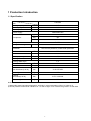
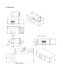
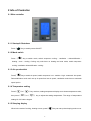
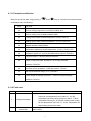
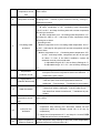
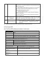
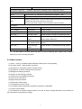
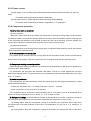
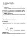
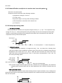
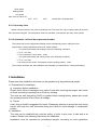
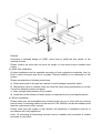
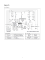
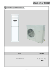
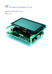
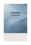
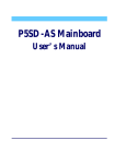
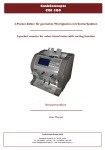
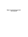
Water Cooled Packaged Unit User Manual Index 1 Production Introduction .................................................................................................. 2 1.1 Specification ......................................................................................................................................... 2 1.2 Dimension ............................................................................................................................................ 3 2 Info of Controller.............................................................................................................. 4 2.1 Wire controller ...................................................................................................................................... 4 2.1.1 Startup & Shutdown ...................................................................................................................................... 4 2.1.2 Mode switch ................................................................................................................................................. 4 2.1.3 Air speed switch............................................................................................................................................ 4 2.1.4 Temperature setting....................................................................................................................................... 4 2.1.5 Sleeping display ............................................................................................................................................ 4 2.1.6 Timing setting ............................................................................................................................................... 5 2.1.7 Canceling ..................................................................................................................................................... 5 2.1.8 Key lock........................................................................................................................................................ 5 2.1.9 Parameter query ........................................................................................................................................... 5 2.1.10 Fahrenheit and Celsius switching:............................................................................................................... 5 2.1.11 Parameter modification ............................................................................................................................... 6 2.1.12 Fault code .................................................................................................................................................. 6 2.2 The Control PCB .................................................................................................................................. 8 2.2.1 The I/O and DIP switching description of control panel ................................................................................. 8 2.2.2 Main function ............................................................................................................................................... 9 2.2.3 Power on sets ............................................................................................................................................. 10 2.2.4 Compressor protection ................................................................................................................................ 10 2.2.5 Sensor open/short circuit............................................................................................................................. 12 2.2.6 No pump output .......................................................................................................................................... 13 2.2.7 Cooling mode ............................................................................................................................................. 13 2.2.8 Ventilation module ...................................................................................................................................... 13 2.2.9 Dehumidification mode(fresh air models don’t have this pattern)............................................................... 14 2.2.10 Heat pump heating mode........................................................................................................................... 14 2.2.11 four-way valve........................................................................................................................................... 15 2.2.12 Automatic cold and hot replacement model ................................................................................................ 15 3 Installation ...................................................................................................................... 15 4 Commissioning .............................................................................................................. 18 5 Maintenance ................................................................................................................... 18 6 Common Malfunction and Treatment ........................................................................... 19 Appendix ........................................................................................................................... 20 1 1 Production Introduction 1.1 Specification Model Item Cooling capacity Rated input power Rated input current CSU 085 TR Kw A 8.5 8.2 14.8 Power Supply Compressor 380V/50Hz/3Ph Type Scroll Qty 1pc Power 9350w Refrigerant Refrigerant charge R407C G 4500 High/low pressure protection, over-heat protection, over-current protection, water-break protection Protection Air flow CFM 3529 Power w 1100 Static pressure Pa 120 m3/h 6.8 Cooling Water Flow 1.2” Cooling Water Pipe Water resistance kPa 32 dB(A) 51 Net dimension(L*W*H) mm 2110*975*654 Net weight Kg 285 Packing dimension(L*W*H) Mm 2170*1100*800 Gross weight Kg 300 Noise Notes: 1) Water side water inlet/outlet temperature: 30ºC/35ºC, indoor temperature: DB 27 ºC, WB 19 ºC. 2) Sound pressure measured at a distance of 1 m and a height of 1.5 m above the ground in a clear field. 2 1.2 Dimension 3 2 Info of Controller 2.1 Wire controller 2.1.1 Startup & Shutdown Press《 》key to switch power ON/OFF. 2.1.2 Mode switch Press 《 》key to switch mode, switch sequence: cooling – ventilation – dehumidification – heating – auto - cooling. Cooling only units have no heating and auto mode, switch sequence: cooling- ventilation-dehumidification- cooling. 2.1.3 Air speed switch Press《 》key to switch air speed, switch sequence: Low - medium - high - automatic- low speed. Dehumidification mode can’t set up air speed but low air speed; ventilation mode has no automatic speed option. 2.1.4 Temperature setting Press《 then press《 》or《 》 key one time, setting temperature display zone shows temperature value, 》or《 》 key to adjust the setting temperature. The range of temperature setting:16~30 Celsius degree. 2.1.5 Sleeping display When in the mode of cooling, heating or auto, press《 4 》key can set up the sleeping mode or not. After setting sleeping mode, it takes about 8 hours to exit sleeping mode automatically. 2.1.6 Timing setting Press 《 》key one time, timing symbol blinking display, fault code area display “--”, which means timing setting undone. Then press 《 》or《 》key can set up the time, the unit is hour. When reduced to 0,it displays “--”. Exiting the timing setting when in timing mode, timing symbol keep blinking. 2.1.7 Canceling Press 《 》key can exit in whatever menu. Long press 《 》key for 3 seconds, which can cancel all the timing setting. 2.1.8 Key lock Long pressing 《 》key for 3 seconds can enter key lock-out state, then will display a symbol of lock, which it is effective only for power ON/OFF key for common clients. Exit the key lock-out state in the same way. 2.1.9 Parameter query When in key lock-out state, long pressing 《 》or《 》key for 3 seconds can enter parameter query menu as following: Temperature Trip-zone Temperature zone C0 Trip-zone zone Return air C2 Outlet water temperature coil C3 Inlet water temperature temperature C1 Indoor temperature 2.1.10 Fahrenheit and Celsius switching: When in lock-out state, press 《 》and《 》key for 3 seconds, which can realize the switch between Fahrenheit and Celsius. 5 2.1.11 Parameter modification When in key lock-out state, long pressing《 》and《 》key for 3 seconds can enter parameter modification menu as following: Temperature zone Trip-zone d0 Defrost exiting temperature (10-30℃), Default 18℃ d1 Defrost exiting time (5-20Min),Default 10Min d2 Cooling recycle water protect temperature 0-20℃,Default 4℃ d3 Heating recycle water protect temperature -10-10℃,Default 4℃ d4 Network address 0-99,Default 0 d5 Temperature difference protect temperature(0-20℃)Default 10℃ d6 0 defaults to power off, 1recover the state before power off, Default 0 d7 0 Defrost mode 1,1 Defrost mode 2,Default 0 d8 0 With Cooling inlet water protection,1 No Cooling inlet water protection ,Default 0 d9 0 No Anti cold air protection, 1 With Anti cold air,, Default 1 da Anti-cold air declines range(0-10)Default 0 db 0 With refrigerant leakage protection, 1 Without refrigerant leakage protection, Default 1 2.1.12 Fault code Code Fault Fault type ① when compressor working for 15 minutes in cooling state, 4 Refrigerant leakage indoor fan coil temperature can’t reduce 2℃ for 10s, compressor will stop working and give an alarm. ②when compressor working for 15 minutes in heating state, indoor fan coil temperature can’t rise 2℃ for 10s, compressor will stop working and give an alarm. 5 return air temperature sensor fault sensor open circuit or short circuit, or Mainboard sensor socket with poor contact. 6 6 Indoor fan coil temperature sensor sensor open circuit or short circuit, or Mainbord sensor socket with poor contact. fault When Indoor fan coil temperature is ≥68℃ in heating state. 8 Compressor overload dropping to 50℃ or below, system automatic recovery. cooling is without this function. (1) cooling/dehumidification mode; ★ when compressor is off : Circulating water temperature <A+2℃or>40℃, and keep for 20s,system will not start compressor and will give an alarm. ★ when compressor is on:Circulating water temperature <A℃ and keep for 180s or >47℃ and keep for 20s, compressor will be off and give an alarm. (2)heating mode; 9 Circulating water protection ★when compressor is off:Circulating water temperature <B+4℃ or>30℃, and keep for 20s,system will not start compressor and will give an alarm. ★when compressor is on:r Circulating water temperature <B℃ or>32℃ and keep for20s, compressor will be off and give an alarm. If it isn’t in the above conditions, system will automatic recovery the normal state. A- adjustable range 0-20℃, the ex-factory Settings is 4℃ B- adjustable range -10℃-10℃, the ex-factory Settings is 4℃ 10 11 low-pressure protection cut off High pressure protection disconnects ① lack of refrigerant;②low pressure switch damage;③the line open circuit from low pressure switch to mainboard;④ mainboard is poor contact ① refrigerant too much;②high pressure switch is damaged; ③the line open circuit from high pressure switch to mainboard;④ice blockage;⑤mainboard is poor contact ① a lack of water;②water pump not running or pump failure; 17 19 water flow switch ③water flow switch is damaged; ④the line open circuit from water flow switch to mainboard;⑤mainboard is poor contact Inlet water sensor open circuit or short circuit, or Mainboard sensor socket with temperature sensor fault poor contact. ① indoor fan coil temperature ≤0℃ keep at least one munite and compressor keep working over 10munites, outdoor fan and 25 indoor fan coil antifreeze compressor switch are off(water cooled unit is off only for compressor); ② indoor fan coil temperature≥12℃ and keep for 1munite,并持续 1 分钟,fault will recovery automatically. 26 water temperature ①after compressor keep working for 3minutes, water temperature difference between difference between inlet and outlet ≤10℃. 7 inlet and outlet ②Inlet water temperature> outlet water temperature when in cooling state, or Inlet water temperature< outlet water temperature when in heating state. when the above cases happen and keep for over 2 minutes, all the modular compressor stop immediately and give an alarm, which need reset manually or restart. Temperature difference value: cooling outlet water temperature-cooling inlet water temperature when in cooling state. cooling inlet water temperature-cooling outlet water temperature when in heating state. Indoor fan coil 26 overheating when indoor fan coil temperature≥57℃,indoor fan run in high speed and compressor keep working. When indoor fan coil temperature≦50℃,system will recovery normal state. ① communication line connection is not correct;②socket is 48 Communication fault loose contact undesirable;③PCB plate socket is cold solder joint PS:If there are multiple failures occur, the fault code will be displayed each one. 2.2 The Control PCB 2.2.1 The I/O and DIP switching description of control panel Analog quantity input Input serial number Name AI1 Return air temperature sensor(R25=10KΩ/3450) AI2 Indoor coil temperature sensor(R25=10KΩ/3450) AI3 Circulating output water temperature sensor(R25=10KΩ/3450) AI4 Circulating input water temperature sensor(R25=10KΩ/3450) DI(connecting passive switching, public side provide DC12V) Input serial num Name DI1 Water flow switch(opto-isolator) DI2 High-pressure switch(opto-isolator) DI3 Low-pressure switch(opto-isolator) model selection S2 air speed selection: OFF = three-speed fan;ON = single speed fan; S3 Fresh air function OFF = without, ON = with S4 water cooled,air cooled OFF = air cooled,ON = water cooled selection S5 Shield some function relative to indoor coil OFF = without,ON = with S6 cooling only or heat pump OFF = heat pump,ON = cooling only selection 8 S7 electrical heating selection OFF = without,ON = with Input power range 100 ~ 256VAC input,built-in switching power,voltage sag 150ms Communication mode CN7-1 4 cord system TTL, Maximum communication distance 30m CN7 3 cord system TTL, Maximum communication distance 30m RS485 communication, communication cable recommend to use Shielded CN8 Twisted Pair with cross section for 0.75 mm². It can provide power supply of DC12V/200mA towards exteral DO section Output serial number Name Remarks DO7(25A/5A) Compressor Output AC220V DO6(25A/5A) Electrical heating Output AC220V cooling only without this item DO5(5A) Four-way valve Output AC220V cooling only without this item DO4(5A) Indoor fan low speed Output AC220 (three speed fan low speed, Single speed outlet port) DO3(5A) Indoor fan Output AC220V(three speed fan intermediate intermediate speed speed) Indoor fan high Output AC220V(three speed fan high speed) DO2(5A) speed DO1(5A) Water pump Passive output ps:The dial switch of control panel had been set up for machine type, please don’t change it arbitrarily to avoid occuring the fault!!! 2.2.2 Main function (1) mode:cooling- ventilation-dehumidification-heating-auto cooling/heating (2) air speed indoor:high-medium-low speed (3) protection for compressor keep 3 minutes to start (4) compressor overload: heating overload function (5) Refrigerant leakage protection (6) Inside coil anti-freezing protection (7) Inside fan coil overheating protection (8) Low pressure protection. (9) High pressure protection (10) Water flow switch failure (11) Temperature sensor Failure (12) Circulating water temperature protection parameter is adjustable (13) Timing on/off setting. (14) Compressor is random delayed switch on in order to reduce voltage fluctuation. Only effective to the compressor at first pitching-in stage. 9 2.2.3 Power on sets A) After power on, the system get the latest parameters from the permanent memory in the main board: Circulating water temperature protection parameters B) If the data is wrong, system will start with the following default Settings: Circulation water temperature protection: refrigeration 4 ℃, heating 4℃ 2.2.4 Compressor protection A) compressor start up protection (1) 3min protection When the system needs to be up loaded, the compressor is allowed to start up after it meet minimum 3 minutes protection. It will shorten the time when the four-way valve commutation system reversing, that is the compressor be allowed to start up after 4s when four-way valve reversing. It can be allowed only one shorten compressor protection time every time the four-way valve reversing. (2) Hardware protection Once the power is cut off and the power supply again, compressor startup latency time is 180 seconds 【The compressor protection time】 B) 90 seconds minimum running time The system has 90 seconds minimum running time for the compressor make sure the oil has enough time to return to the system. Then the compressor can be stopped in the current operation mode. C) Compressor heating overload protection It will take effective while the compressor is running and the temperature in the fan coil is greater than or equal to 68°C when heating. The compressor will stop when the protection take effect. The fan run under against the cold wind model in the heating mode. The system will recover automatically when the temperature inside coil drops to 50 ° C or below. D) Inside coil antifreeze In the refrigeration and dehumidification mode, the system enter into the inside coil antifreeze if it meet all the following conditions: ★Inside coil temperature is 0 ℃ lasting for at least 1 minute, moreover ★The compressor running more than 10 minutes。 The compressor will be shut down if meet conditions above. The system recover automatically when inside coil sensor temperature arrive or above 12 ° C for at least 1 minute. E) Refrigerant leakage(note that take the sample of the temperature to make comparison should be the value when the compressor start up and the value after the compressor running 15 min ) (1) Heating status: when the compressor running for15 minutes, the compressor will be shut down and shows lack of fluoride protection if the indoor coil temperature can not rise of 2 ℃ lasting for 10 seconds, (2) cooling status: when the compressor running for15 minutes, the compressor will be shut down 10 and shows lack of fluoride protection if the indoor coil temperature can not drop of 2 ℃ lasting for 10 seconds,. The compressor will be stopped and alarm if fluorine leakage failure detection in the first time. After 3 minutes compressor protection, it will re-detect according to the above procedure but the cycle shortened to five minutes, if still failed, lock the fault and reset by manually switching on/off. The cycle is 15 + 5 minutes. Only the inside fan can run(Heating by anti-air cooling mode)and compressor can't start anymore when lack of fluoride to protection occurred. Turn it off to recover. This protection no longer testing in the current cycle mode until the next compressor pitching-in cycle if confirmed no leak fluorine. Terminate the lack of fluorine testing in following conditions: ※ Under the system ventilation mode, or ※ The compressor is unloading due to meeting the setting temperature, or ※ Under inside coil defrosting in refrigeration and dehumidification mode. Note:Setting whether cancel the refrigerant leakage by remote parameter controller, cancel refrigerant leakage when the db is 0, the db is 1 refrigerant leakage can make. F) Heating prevent inside coil from overheating Interior wind jump to high speed when the inside coil temperature rise to 57 ℃ or above. The system back to normal when the coil temperature ≦ 50 ℃. G) Low-pressure protect input The compressor is in running status, the compressor will be shut down and alarming when low-pressure protect disconnect time≧ 30 seconds. The system will automatically return to normal once the low-pressure switch is reset at closed status. (1) It will block the detection at first 30s after the compressor start up. (2) The low pressure switch must be off before the compressor start up, otherwise it will alarm. H) High pressure protection input High pressure switch is on in the normal circumstances. The compressor will be shut down and alarming if the high pressure protection disconnect and lasting for 1 seconds,. High pressure switch must be switch on before the compressor start up, or it will alarm. The system will automatically return to normal once in the closed state, I) The temperature of the cooling water protection (1) Refrigeration/dehumidification operation mode; ★The compressor is shut down: Circulating water temperature < A + 2 ℃ or > 40 ℃ and this situation lasting for 20 seconds, the system won’t start up the compressor and alarming at the same time. ★The compressor is running: Circulating water temperature < A ℃ lasting for 180s or >47 ℃ lasting for 20S, The compressor will be shut down and alarming. (2) Heating operation mode; ★The compressor is shut down: Circulating water temperature < B + 4 ℃ or > 30 ℃ and this situation lasting for 20 seconds, the system won’t start up the compressor and alarming at the same time. 11 ★The compressor is running:Circulating water temperature < B ℃ lasting for 180s or >32 ℃ lasting for 20S, The compressor will be shut down and alarming. The system automatically return to normal if it is not under the situation above lasting for 20s. A-Adjustable range 0-20 ℃, the factory default value is 4 ℃ B-Adjustable range -10-10 ℃, the factory default value is 4 ℃ J) Cooling water flow protection Normally, the water flow switch should be in the closed state after the pumps starting for 35 seconds. The compressor will be shut down and alarming if the water flow switch off lasting for 3s. The compressor allows to be start up if alarms lasts 60 seconds and recover. The flow switch must be on before the compressor starting, or it will alarm. The system will automatically return to normal once it switch on. If the flow fault appears 2 times continuous within 30 minutes of, except for the above shut down operation and should alarming immediately. The failure cannot be automatically restored, it is only can be restart through the open key. Only the water flow switch has been restore then the fault alarm can be canceled and restarting K) The fault of difference of inlet and outlet water temperature ( inlet water sensor setting can detect this failure at this moment) Starting to test each inlet/outlet water temperature difference of heat exchanger system when the compressor is running for 18. All of the compressors in this module must be stopped immediately if difference of inlet/outlet temperature do not tally with the actual operating mode (cooling: cooling outlet water is lower than the cooling inlet water, heating: cooling outlet water is higher than the cooling inlet water) or the temperature difference is more than 10℃ (Adjustable 0-20 ℃) lasting for 120s. The fault need to manual reset or power off to restart after the failure alarm output. Cooling running: cooling outlet water temperature-cooling returning water temperature. Heating running: cooling returning water temperature- cooling outlet water temperature. 2.2.5 Sensor open/short circuit A) Returning air temperature sensor It’s 2 seconds for the fault recovery confirmation. The system prohibits the compressor to start up when inspecting the sensor fault continuous. The internal fan output low speed wind if it set to automatically speed wind, otherwise output according to the speed set. 12 B) Temperature sensor of the internal coil tube It’s 2 seconds for the fault recovery confirmation. Non heating mode: a) If the compressor running up, it will begin to inspect after running two min. b) If the compressor don’t start up, it will inspect Continuous. Sensor failure: a) Shows fault code。 b) Refrigeration, dehumidification: Shielding internal coil involve controlling and unit working with fault. c) Heating [heat pump model]: Compressor start-up then internal fan running under lower speed for 20 seconds and then to the set wind speed. Then compressor stop and internal fan running for 30s, then stop 30s start 20s stop 30s …until the compressor meet running with loading.The internal fan will stay stop until fault released allows the compressor pitching-in if has other fault stop the compressor for running such as high pressure jump. C) Circulating water temperature sensor It’s 2 seconds for the fault recovery confirmation. Continuous inspection, for example the fault of the sensor ,the system prevent compressor from tart-up and low speed wind running until the sensor fault is cleared. 2.2.6 No pump output Start condition: system start, the compressor is not allowed to start up at the first 30s after the water pump start up. Shut down condition: system shut down, ventilation mode 2.2.7 Cooling mode Under cooling mode, the compressor begin to start up if Tr-Ts≧0.5℃. The compressor stop running and enter into the time protection functionth if Tr-Ts≦(-1.0)℃. Indoor wind speed running according to the set, the wind speed of the system depend on the following conditions when the wind speed set automatically. Wind speed High medium low -0.5 0.5 1.5 ΔTºC(Tr indoor temperature-Ts set temperature ) 2.2.8 Ventilation module Only high, medium and low speed can choose. Compressor, circulating pump and four way valve are 13 shut down. 2.2.9 Dehumidification mode(fresh air models don’t have this pattern) Indoor fan runs at low speed. Compressor will be shut down under following condition: ※compressor running for 10 min or ※Tr-Ts≦(-1.0)℃ Compressor begin to running under following condition: ※The compressor is shut down for 5 minutes and ※Tr-Ts ≧0.5℃ 2.2.10 Heat pump heating mode No fresh air function: With time protection condition, the compressor begin to start up if ≦(-1.0)℃. The compressor stop runing if Tr-Ts≧1.5℃. Indoor wind speed running according to the set, the wind speed of the system depend on the following conditions when seting the auto speed wind: low-speed wind 20s befor the compressor start up, then set wind speed. Wind speed High medium low -1.0 1.0 2.0 ΔTºC(Ts set temperature-Tr indoor temperature) Cold wind resistant: After the first time electricity or change the mode, first, the indoor fan is shuting down under the condition of the compressor is allow to start. The indoor fan is allowed to start only the temperature of the indoor coil ≧ (30 - dA) ℃. After the indoor fan starts, the indoor fan is shut down if the indoor coil temperature ≤(25 - dA) ℃. If the indoor coil temperature ≧ (40 - dA) ℃,it will running at setting speed. Wind speed Setting speed Low speed Shut down the indoor fan 25℃ 30℃ 40℃ indoor fan coil temperature Note:dA is the range of decline against cold wind , defualt is 0C(0-10Cadjustable), The cold wind resistant will be canceled when the line control parameter is d9. It has the funcition when d9 is 1. Clear spare heat control The compressor will be shut down when heating and wind speed as follows: only in setting wind speed has the function of Clear spare heat and compressor don’t start and the wind at low speed when in the auto wind speed. 14 Wind speed Setting speed Low speed Shut down the indoor fan 30℃ 37℃ 40℃ internal fan coil temperature 2.2.11 four-way valve System will open the four-way valve in heating mode. The valve can only be opened after 60 seconds the compressor stopped. The compressor allows to start after 4 seconds the four-way valve opened. 2.2.12 Automatic cold and hot replacement model The system will convert refrigeration/heating modeI automatically when in different indoor temperature, set ting temperature and mode switch delayed. The system will switch into heating mode in the following conditions: Ts-Tr > 2℃ and The compressor is shut down> 10min The system will switch into cooling mode in the following conditions: Tr-Ts > 2℃ and According to the model: Compressor/ electric heating closed > 10min The concrete operation are same between and automatic non-automatic for cooling and heating. 3 Installation Please note that installation and tests can be operated only by professional people. 1). Preparations for installation. a). Inspection before installation. Please check if there’s damage to any parts of units after receiving the cargos, also check all items according to packing list to avoid any missing. The units are well charged by R407c in system before leaving factory, please also check the system pressure to see if there is leakage. b). Transit Hoist, sling or forklift is suggested for transit. Please pay attention to protect the unit during transit, and keep the units horizontal during the transit to avoid damage to compressor system. 2). Installation The units can be installed freely onto the ceiling, in toilet, in any room, in stair well or at outdoor. Please note following instructions for installation. Installation must be operated by professional people, according to local regulations 15 exactly. Please consider the space for water pipes, power wires, and that of maintenance. 16 Remark: According to standard design of CUBE, users have to install the flow switch, to the interface of units. Please confirm the hoist part can bear the weight of units when they’re installed onto ceiling. 3). Water Pipe installation All pipe installation must be operated according to local regulations completely. And, try best to reduce the parts with curve or grade. Thermal isolation is not necessary for this system. Please pay attention to following instructions. a). Shake proof parts to the pipe are needed, to avoid leakage caused by shake. b). Maintenance valve is needed, users can close the valve during maintenance to cut the connection between system and pipes. c). Keep enough water pressure in the system. d). Install filter at the entrance of water pump, to stop impurity from entering the system. 4). Electric installation. Please make sure all wires/cables are connected well, are not in touch with any running parts of units. Connecting cables of units must be YZW-300/500, and all wires/cables must meet the requirement of this manual. Please make sure the system is well earthed. All operations of installation must be in accordance with local regulations. Note:All protecting & interlocking devices must be installed and connected to related terminals in control box. 17 4 Commissioning Please check the installation of units again and the voltage of power supply before the commissioning. If units with 3 phases have no response after connected to power, please cut off power and adjust the connection of any of 2 phases. Please check the running status of main parts, for example, the noise and shake of motor/compressor, the running direction of motor, the noise of system and duct, etc. Please pay attention to following points during commissioning. a. Indoor temp setting of controller should be reasonable, not too high or too low. b. Please keep the indoor controller away from computer, TV, and other home appliances, to avoid signal jam between different control systems. c. Please keep the doors and windows closed during the operation of units, to avoid energy lost and low energy efficiency. d. Please do not operate with wet hands, do not wash the units with water directly, and controller and PCB box of units should be well damp proof. e. After using the units for some hours, rooms should be well ventilated and kept fresh air for around 15%. Please cut off the power supply of units and call CUBE distributors for help if any accidents happen during operation, including adust smell, sparkles of electric parts, smokes, and so on. Please do not check the units personally in these cases, but waiting for the professional service people. 5 Maintenance 1). Electric maintenance. a). There should be exclusive power supply for the units, with fluctuation of voltage within ±10%. Auto air switch is required for system, and its rated current should be 1.5 times of running current of system. b). System must be well earthed. c). On/Off should be operated no more than 4 times per hour. Electrical control box should be well damp proof. d). There’s phase protection in system for 3 phase units. Please restart the units and adjust the phase connections if system has no response at the first time of power on. 2). Maintenance of units. a). Please prepare well for following points before using units in different seasons. Make sure to connect compressors to power supply for more than 12 hours before units are power on, to reduce the liquid refrigerant in compressors, increase the oil temp, and reduce abrasion of compressor. Check the start and operation of units for the initial use of each time, and cut of power supply immediately if anything wrong is found. b). Clean the return air filters monthly, to guarantee the smooth operation of units. All cleaning must be operated by professional people. 18 c). Check and clean the drainage pipe before starting the units, to guarantee drainage of condensing water. Also, check and clean the drainage pipe in winter to avoid freeze down. d). Do not disassemble the units or maintain personally, please call CUBE distributors for help and wait for service people if any faults are found. e). Make sure to cut off power supply if units will not be used for certain time of period, or there’ll still be some power consumption. And, remember to connect units to power for no less than 12 hours before starting the units. f). All maintenance must be operated when all power supply is cut, to avoid accidents. 6 Common Malfunction and Treatment NO. Description reason treatment 1 Units do not operate with power supply Reverse protection does not function. Indoor temp controller is not adjusted well. Adjust phase connection (for 380V) / Check power supply Adjust indoor temp controller. 2 Low pressure switch protector functions Low refrigerant charge, leakage in system, fault in pressure switch, low air/water flow. Charge refrigerant, fix the leakage, adjust/change the pressure switch, clean filters 3 High exhaust air pressure Sundries in condenser, high refrigerant charge, low air/water flow Clean condenser, reduce refrigerant, clean filters. 4 High inspiring air pressure Over fresh air, disabled thermal isolation of duct, high refrigerant charge. Reduce fresh air, repair duct, reduce refrigerant. 5 Low inspiring air pressure Block in air filter, block in duct, low running speed of ventilator, short circuit in duct, low environmental temp, low refrigerant charge Clean air filter, clean block sundries, adjust speed of ventilator, modify duct, charge refrigerant. 6 Big operation noise Faults in compressor, over refrigerant charge, faults in air system, parts not well screwed, designing problems of duct Change compressor, reduce refrigerant charge, repair ventilator, fix screws, check duct design and repair. 19 Appendix Wiring Diagram 20