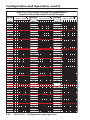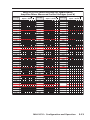
1
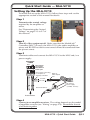
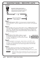
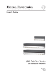
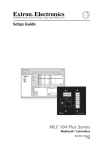
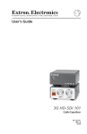
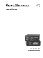
User’s Manual MLA-VC10 MediaLink Accessory 68-690-01 Rev. B 03 08 Precautions Safety Instructions • English This symbol is intended to alert the user of important operating and maintenance (servicing) instructions in the literature provided with the equipment. This symbol is intended to alert the user of the presence of uninsulated dangerous voltage within the product’s enclosure that may present a risk of electric shock. Caution Read Instructions • Read and understand all safety and operating instructions before using the equipment. Retain Instructions • The safety instructions should be kept for future reference. Follow Warnings • Follow all warnings and instructions marked on the equipment or in the user information. Avoid Attachments • Do not use tools or attachments that are not recommended by the equipment manufacturer because they may be hazardous. Consignes de Sécurité • Français Ce symbole sert à avertir l’utilisateur que la documentation fournie avec le matériel contient des instructions importantes concernant l’exploitation et la maintenance (réparation). Ce symbole sert à avertir l’utilisateur de la présence dans le boîtier de l’appareil de tensions dangereuses non isolées posant des risques d’électrocution. Attention Lire les instructions• Prendre connaissance de toutes les consignes de sécurité et d’exploitation avant d’utiliser le matériel. Conserver les instructions• Ranger les consignes de sécurité afin de pouvoir les consulter à l’avenir. Respecter les avertissements • Observer tous les avertissements et consignes marqués sur le matériel ou présentés dans la documentation utilisateur. Eviter les pièces de fixation • Ne pas utiliser de pièces de fixation ni d’outils non recommandés par le fabricant du matériel car cela risquerait de poser certains dangers. Sicherheitsanleitungen • Deutsch Dieses Symbol soll dem Benutzer in der im Lieferumfang enthaltenen Dokumentation besonders wichtige Hinweise zur Bedienung und Wartung (Instandhaltung) geben. Dieses Symbol soll den Benutzer darauf aufmerksam machen, daß im Inneren des Gehäuses dieses Produktes gefährliche Spannungen, die nicht isoliert sind und die einen elektrischen Schock verursachen können, herrschen. Achtung Lesen der Anleitungen • Bevor Sie das Gerät zum ersten Mal verwenden, sollten Sie alle Sicherheits-und Bedienungsanleitungen genau durchlesen und verstehen. Aufbewahren der Anleitungen • Die Hinweise zur elektrischen Sicherheit des Produktes sollten Sie aufbewahren, damit Sie im Bedarfsfall darauf zurückgreifen können. Befolgen der Warnhinweise • Befolgen Sie alle Warnhinweise und Anleitungen auf dem Gerät oder in der Benutzerdokumentation. Keine Zusatzgeräte • Verwenden Sie keine Werkzeuge oder Zusatzgeräte, die nicht ausdrücklich vom Hersteller empfohlen wurden, da diese eine Gefahrenquelle darstellen können. Instrucciones de seguridad • Español Este símbolo se utiliza para advertir al usuario sobre instrucciones importantes de operación y mantenimiento (o cambio de partes) que se desean destacar en el contenido de la documentación suministrada con los equipos. Este símbolo se utiliza para advertir al usuario sobre la presencia de elementos con voltaje peligroso sin protección aislante, que puedan encontrarse dentro de la caja o alojamiento del producto, y que puedan representar riesgo de electrocución. Precaucion Leer las instrucciones • Leer y analizar todas las instrucciones de operación y seguridad, antes de usar el equipo. Conservar las instrucciones • Conservar las instrucciones de seguridad para futura consulta. Obedecer las advertencias • Todas las advertencias e instrucciones marcadas en el equipo o en la documentación del usuario, deben ser obedecidas. Evitar el uso de accesorios • No usar herramientas o accesorios que no sean especificamente recomendados por el fabricante, ya que podrian implicar riesgos. Warning Power sources • This equipment should be operated only from the power source indicated on the product. This equipment is intended to be used with a main power system with a grounded (neutral) conductor. The third (grounding) pin is a safety feature, do not attempt to bypass or disable it. Power disconnection • To remove power from the equipment safely, remove all power cords from the rear of the equipment, or the desktop power module (if detachable), or from the power source receptacle (wall plug). Power cord protection • Power cords should be routed so that they are not likely to be stepped on or pinched by items placed upon or against them. Servicing • Refer all servicing to qualified service personnel. There are no userserviceable parts inside. To prevent the risk of shock, do not attempt to service this equipment yourself because opening or removing covers may expose you to dangerous voltage or other hazards. Slots and openings • If the equipment has slots or holes in the enclosure, these are provided to prevent overheating of sensitive components inside. These openings must never be blocked by other objects. Lithium battery • There is a danger of explosion if battery is incorrectly replaced. Replace it only with the same or equivalent type recommended by the manufacturer. Dispose of used batteries according to the manufacturer’s instructions. Avertissement Alimentations• Ne faire fonctionner ce matériel qu’avec la source d’alimentation indiquée sur l’appareil. Ce matériel doit être utilisé avec une alimentation principale comportant un fil de terre (neutre). Le troisième contact (de mise à la terre) constitue un dispositif de sécurité : n’essayez pas de la contourner ni de la désactiver. Déconnexion de l’alimentation• Pour mettre le matériel hors tension sans danger, déconnectez tous les cordons d’alimentation de l’arrière de l’appareil ou du module d’alimentation de bureau (s’il est amovible) ou encore de la prise secteur. Protection du cordon d’alimentation • Acheminer les cordons d’alimentation de manière à ce que personne ne risque de marcher dessus et à ce qu’ils ne soient pas écrasés ou pincés par des objets. Réparation-maintenance • Faire exécuter toutes les interventions de réparationmaintenance par un technicien qualifié. Aucun des éléments internes ne peut être réparé par l’utilisateur. Afin d’éviter tout danger d’électrocution, l’utilisateur ne doit pas essayer de procéder lui-même à ces opérations car l’ouverture ou le retrait des couvercles risquent de l’exposer à de hautes tensions et autres dangers. Fentes et orifices • Si le boîtier de l’appareil comporte des fentes ou des orifices, ceux-ci servent à empêcher les composants internes sensibles de surchauffer. Ces ouvertures ne doivent jamais être bloquées par des objets. Lithium Batterie • Il a danger d’explosion s’ll y a remplacment incorrect de la batterie. Remplacer uniquement avec une batterie du meme type ou d’un ype equivalent recommande par le constructeur. Mettre au reut les batteries usagees conformement aux instructions du fabricant. Vorsicht Stromquellen • Dieses Gerät sollte nur über die auf dem Produkt angegebene Stromquelle betrieben werden. Dieses Gerät wurde für eine Verwendung mit einer Hauptstromleitung mit einem geerdeten (neutralen) Leiter konzipiert. Der dritte Kontakt ist für einen Erdanschluß, und stellt eine Sicherheitsfunktion dar. Diese sollte nicht umgangen oder außer Betrieb gesetzt werden. Stromunterbrechung • Um das Gerät auf sichere Weise vom Netz zu trennen, sollten Sie alle Netzkabel aus der Rückseite des Gerätes, aus der externen Stomversorgung (falls dies möglich ist) oder aus der Wandsteckdose ziehen. Schutz des Netzkabels • Netzkabel sollten stets so verlegt werden, daß sie nicht im Weg liegen und niemand darauf treten kann oder Objekte darauf- oder unmittelbar dagegengestellt werden können. Wartung • Alle Wartungsmaßnahmen sollten nur von qualifiziertem Servicepersonal durchgeführt werden. Die internen Komponenten des Gerätes sind wartungsfrei. Zur Vermeidung eines elektrischen Schocks versuchen Sie in keinem Fall, dieses Gerät selbst öffnen, da beim Entfernen der Abdeckungen die Gefahr eines elektrischen Schlags und/oder andere Gefahren bestehen. Schlitze und Öffnungen • Wenn das Gerät Schlitze oder Löcher im Gehäuse aufweist, dienen diese zur Vermeidung einer Überhitzung der empfindlichen Teile im Inneren. Diese Öffnungen dürfen niemals von anderen Objekten blockiert werden. Litium-Batterie • Explosionsgefahr, falls die Batterie nicht richtig ersetzt wird. Ersetzen Sie verbrauchte Batterien nur durch den gleichen oder einen vergleichbaren Batterietyp, der auch vom Hersteller empfohlen wird. Entsorgen Sie verbrauchte Batterien bitte gemäß den Herstelleranweisungen. Advertencia Alimentación eléctrica • Este equipo debe conectarse únicamente a la fuente/tipo de alimentación eléctrica indicada en el mismo. La alimentación eléctrica de este equipo debe provenir de un sistema de distribución general con conductor neutro a tierra. La tercera pata (puesta a tierra) es una medida de seguridad, no puentearia ni eliminaria. Desconexión de alimentación eléctrica • Para desconectar con seguridad la acometida de alimentación eléctrica al equipo, desenchufar todos los cables de alimentación en el panel trasero del equipo, o desenchufar el módulo de alimentación (si fuera independiente), o desenchufar el cable del receptáculo de la pared. Protección del cables de alimentación • Los cables de alimentación eléctrica se deben instalar en lugares donde no sean pisados ni apretados por objetos que se puedan apoyar sobre ellos. Reparaciones/mantenimiento • Solicitar siempre los servicios técnicos de personal calificado. En el interior no hay partes a las que el usuario deba acceder. Para evitar riesgo de electrocución, no intentar personalmente la reparación/mantenimiento de este equipo, ya que al abrir o extraer las tapas puede quedar expuesto a voltajes peligrosos u otros riesgos. Ranuras y aberturas • Si el equipo posee ranuras o orificios en su caja/alojamiento, es para evitar el sobrecalientamiento de componentes internos sensibles. Estas aberturas nunca se deben obstruir con otros objetos. Batería de litio • Existe riesgo de explosión si esta batería se coloca en la posición incorrecta. Cambiar esta batería únicamente con el mismo tipo (o su equivalente) recomendado por el fabricante. Desachar las baterías usadas siguiendo las instrucciones del fabricante. 安全须知 • 中文 警告 这个符号提示用户该设备用户手册中 有重要的操作和维护说明。 电源 • 该 设 备 只 能 使 用 产 品 上 标 明 的 电 源 。 设 备 必须使用有地线的供电系统供电。 第三条线 (地线)是安全设施,不能不用或跳过。 这个符号警告用户该设备机壳内有暴 拔掉电源 • 为安全地从设备拔掉电源,请拔掉所有设备后 或桌面电源的电源线,或任何接到市电系统的电源线。 露的危险电压,有触电危险。 电源线保护 • 妥善布线, 避免被踩踏,或重物挤压。 注意 阅读说明书 • 用 户 使 用 该 设 备 前 必 须 阅 读 并 理 解所有安全和使用说明。 保存说明书 • 用户应保存安全说明书以备将来使 用。 遵守警告 • 用户应遵守产品和用户指南上的所有安 全和操作说明。 维护 • 所有维修必须由认证的维修人员进行。 设备内部 没有用户可以更换的零件。为避免出现触电危险不要自 己试图打开设备盖子维修该设备。 通风孔 • 有些设备机壳上有通风槽或孔,它们是用来防止 机内敏感元件过热。 不要用任何东西挡住通风孔。 锂电池 • 不正确的更换电池会有爆炸的危险。 必须使用 与厂家推荐的相同或相近型号的电池。 按照生产厂的 建议处理废弃电池。 避免追加 • 不要使用该产品厂商没有推荐的工具或 追加设备,以避免危险。 声明 所使用电源为 A 级产品,在生活环境中,该产品可能会造成无线电干扰。在这种情况下,可能需要用 户对其干扰采取切实可行的措施。 FCC Class A Notice This equipment has been tested and found to comply with the limits for a Class A digital device, pursuant to part 15 of the FCC Rules. Operation is subject to the following two conditions: (1) this device may not cause harmful interference, and (2) this device must accept any interference received, including interference that may cause undesired operation. The Class A limits are designed to provide reasonable protection against harmful interference when the equipment is operated in a commercial environment. This equipment generates, uses, and can radiate radio frequency energy and, if not installed and used in accordance with the instruction manual, may cause harmful interference to radio communications. Operation of this equipment in a residential area is likely to cause harmful interference, in which case the user will be required to correct the interference at his own expense. N This unit was tested with shielded cables on the peripheral devices. Shielded cables must be used with the unit to ensure compliance with FCC emissions limits. Quick Start Guide — MLA-VC10 Setting Up the MLA‑VC10 To install and set up the MLA-VC10, follow these steps and see the appropriate section of this manual for details: Step 1 Determine the control voltage required by the amplifier or mixer. See “Determining the Control Voltage” on pages 2-3 to 2-7 of this manual. Step 2 Turn all of the equipment off. Make sure that the MediaLink® Controller (MLC) (if used), the MLA-VC10, the audio amplifier or mixer, and RS-232 host device are turned off and disconnected from the power source. Step 3 Terminate cables and connect the MLA-VC10 to the MLC and/or a power supply. MLC/RS-232 POWER AB MLA-VC10's front panel MLC/RS-232 Power port Not used for connecting to computers or 3rd party controllers. White or white-striped wire +12 VDC Ground ( ) An external power supply (12 VDC, 1A max.) Ground all devices To Controllers Step 4 Connect to an amplifier or mixer. The wiring depends on the model of amplifier or mixer (see "Wiring" on page 2-8). Ground the chassis of all units together. MLA-VC10 • Quick Start Guide QS-1 Quick Start Guide — MLA-VC10, cont’d AMP/MIXER CONTROL CTRL * The actual maximum control voltage depends on the Configuration DIP switch settings, but the maximum power output will not be reached if the amplifier's control port voltage measures more than 10 VDC. 0 VDC to +10 VDC* Ground ( ) To Amplifier 6 feet (1.8 m) maximum between the MLA-VC10 and the amplifier Step 5 Connect the power cables to a power source and power on the MLA-VC10, MLC/power supply, RS-232 host device, and amplifier or mixer. Step 6 For most MLC units used with the MLA‑VC10, configure the system with the Global Configurator program (see page 3-2) or RS-232 (see page 3-14). The MLC 206 is not supported by Global configurator MLA_VC10_ and the MediaLink control software (included with the MLC) must dip_switch.eps be used (see page 3-10). Step 7 Set the MLA-VC10’s DIP switches to match the voltage determined in step 1. See “DIP switches” on page 3-11, and the reference tables on pages 3-12 and 3-13. ON CONFIGURATION 1 2 3 4 5 6 7 8 Step 8 Test the system by turning the volume knob on the MLC or by sending a volume-related RS-232 command while listening for a change in the volume level and observing the MLA‑VC10’s LED (which should blink). Step 9 If wiring changes are needed, turn off the power and unplug the equipment, make any necessary wiring changes (see "Troubleshooting", page 3-17), and then restore power to the system. N QS-2 When the MLA-VC10 is attached to the control port of some amplifiers, the amplifier's front panel volume control knob is disabled. MLA-VC10 • Quick Start Guide Table of Contents Chapter One • Introduction..................................................... 1-1 About this Manual..................................................................... 1-2 About the MLA-VC10................................................................ 1-2 Chapter Two • Installation and Setup.............................. 2-1 Front and Rear Panel Features............................................... 2-2 Determining the Control Voltage......................................... 2-3 Measuring voltage for a Peavey UMA 35T II amplifier........ 2-4 Measuring voltage for a Biamp Precedence CMA 60 amplifier 2-5 Measuring the voltage for a TOA A-706 amplifier. ............. 2-6 Measuring the voltage for a TOA A-903 amplifier............... 2-7 Wiring. ........................................................................................... 2-8 Wiring the MLC/Power connector......................................... 2-8 Wiring the amplifier/mixer control connector................... 2-11 Wiring TOA 700 Series amplifiers........................................ 2-12 Wiring TOA 900 Series amplifiers........................................ 2-14 Chapter Three • Configuration and Operation. ........ 3-1 Configuration.............................................................................. 3-2 Global Configurator. .............................................................. 3-2 Adding the MLA-VC10 driver.................................................3-2 Configuring the MLC Button for amplifier mute..................3-5 Configuring a GC2 Monitor for amplifier mute....................3-6 Uploading the Configuration File to the MLC.....................3-10 MediaLink® Control Software.............................................. 3-10 DIP switches.......................................................................... 3-11 Table of MLA-VC10 DIP Switch Settings.............................. 3-12 RS-232 control....................................................................... 3-14 Host-to-MLA communications..............................................3-14 MLA-initiated messages........................................................3-14 Error response........................................................................3-14 Using the command/response table....................................3-15 Command/response table for SIS commands................. 3-16 Operation.................................................................................... 3-17 Troubleshooting........................................................................ 3-17 MLA-VC10 • Table of Contents Table of Contents, cont’d Appendix A • Reference Information .............................A-1 Specifications...............................................................................A-2 Included Parts..............................................................................A-3 Cables.............................................................................................A-3 MLA‑VC10 Functional Block Diagram..................................A-3 All trademarks mentioned in this manual are the properties of their respective owners. 68-690-01 Rev. B 03 08 ii MLA-VC10 • Table of Contents MLA-VC10 1 Chapter One Introduction About this Manual About the MLA-VC10 Introduction About this Manual This manual contains information on how to mount, install and operate the Extron MLA-VC10. Unless otherwise stated, in this manual all references to MediaLink Accessory or Volume Control Accessory pertain to the MLA-VC10. About the MLA-VC10 In conjuction with a MediaLink® Controller (MLC), the Extron MediaLink Accessory Volume Control 10 (MLA-VC10) can be used to remotely control the volume output of an audio mixer or amplifier that has a 0 VDC to 10 VDC variable voltage remote control port for volume control. When used with an MLC, the MLA-VC10 can share the MLC's 12 VDC power supply. It can also be installed with an external 12 VDC power supply and a third party RS-232 control device. Refer to the appropriate user's manual for information on how to wire control connections to the controller, amplifier or mixer. N The MLA-VC10 provides a control voltage (supply voltage) of between 0 and 10 VDC. The MLA-VC10 can contol amplifiers that use a higher control voltage but the amplifier's maximum volume will not be reached. This manual describes how to measure the amplifier's control voltage and special requirements for wiring the MLA-VC10 to specific amplifiers. Figure 1-1 shows a typical application of the MLA-VC10. 1-2 MLA-VC10 • Introduction 1 PL DIS FF OOF OONN VC AY R 2 D DV OFF 3 ON PC E M LU VO 4 NF CO IG s 4 IP Plu C 10 ML Ext ron NF CO R IXEL P/MRO AMONT C MLC 104 IP Plus MediaLink Controller ON 1 2 3 IG 4 UR 5 N IO AT 6 7 8 RL CT 12 VDC RS-232 PO W ST ER AT / US ML C PO/RS-2 WE 32 R A B ML A-V C1 0 Control Voltage MLA-VC10 TR BA LE REO STE VE SS L WE I PO LE EB 2 12 ER MPAPLIFI R AM MIN ON LIM R ITE L DUA O MON OFF MPA 122 12 VDC Power Supply Mini Power Amplifier Speakers VCR DVD Figure 1-1 — The Extron MLA-VC10 MLA-VC10 • Introduction 1-3 Introduction, cont’d 1-4 MLA-VC10 • Introduction MLA-VC10 2 Chapter Two Installation and Setup Front and Rear Panel Features Determining the Control Voltage Wiring Installation and Setup Front and Rear Panel Features MLC/RS-232 POWER POWER/ STATUS MLA-VC10 A B 1 2 Figure 2-1 — MLA-VC10 front panel a b Power/Status indicator LED — This LED lights steadily while the MLA-VC10 receives power, and blinks three times when the MLA-VC10 receives valid RS-232 volume setting commands. MLC/RS-232 Power connector — This 5-pole, 3.5 mm captive screw connector is for transmitting and receiving RS-232 signals and for power and ground connections. Connect cables to this port for: • a MediaLink Controller (MLC) and the MLC's 12 VDC power supply, or • an external 12 VDC power supply and a third party RS-232 control device AMP/MIXER CONTROL CONFIGURATION ON 1 2 3 4 5 6 7 8 CTRL 3 4 Figure 2-2 — MLA-VC10 rear panel c d 2-2 Amp/Mixer Control connector — Connect a cable between the amplifier's or mixer's remote control port and this 2-pole 3.5 mm captive screw connector to provide a ground and control voltage for regulating the audio volume. Configuration DIP switches — Set these eight switches to configure the MLA-VC10 for the control voltage required by the amplifier or mixer. See "DIP switches" on page 3-11. MLA-VC10 • Installation and Setup Determining the Control Voltage The MLA-VC10 drives the amplifier's or mixer's remote control port. Different models of amplifier or mixer may require a different voltage to control the audio volume. You need to know the specific voltage requirements of your equipment before you can configure the MLA-VC10 to control it. Sometimes the equipment's manual lists the required voltage, but usually you will have to test the voltage yourself, using a voltmeter. This section describes how to measure the control voltage for some widely used amplifiers. Most amplifiers come in one of two basic configurations: • two-terminal (control and ground) • three-terminal (reference, control, and ground) N The MLA-VC10 works with a wide range of amplifiers. The models shown in this section are included as examples only. The MLA-VC10 is not limited to working with only the amplifiers shown in this manual. The next two pages show how to measure control voltages on "typical" amplifers: the Peavey UMA 35T II (page 2-4) and Biamp Precedence CMA 60 (page 2-5). Following that, two special case amplifiers are described: the TOA 700 series (page 2-6) and 900 series (page 2-7). MLA-VC10 • Installation and Setup 2-3 Installation and Setup, cont’d Measuring voltage for a Peavey UMA 35T II amplifier Control Terminals for Peavey amplifiers usually consist of two screw terminals. In the example shown below, they are labeled "Remote Vol". Use a voltmeter, set to VDC, to measure the voltage. Meter probes correctly oriented Figure 2-3 — Measuring control voltage for a Peavey UMA 35T II: Meter probes are oriented correctly. In figure 2-3, the measured voltage is positive, so the right terminal is the signal connection and the left terminal is ground connection. Write down the measured voltage and which terminal is ground as this will be important when you set the DIP switches. If the voltage is negative (see figure 2-4), the meter's probes are touching the wrong terminals. Meter probes incorrectly oriented Figure 2-4 — Measuring control voltage for a Peavey UMA 35T II: Meter probes are oriented incorrectly. 2-4 MLA-VC10 • Installation and Setup Measuring voltage for a Biamp Precedence CMA 60 amplifier Several Biamp amplifiers have three screw terminals labeled "remote level". In the picture at right, the control voltage is indicated by a C on the panel over the corresponding screw terminal. The ground terminal is indicated with a reference terminal is indicated by a +10v. and the Even if the voltage is indicated, use a voltmeter to measure the voltage between the control terminal and the ground terminal as shown in figure 2-5. Write down the measured voltage and which terminal is ground as this will be important when you set the DIP switches. Figure 2-5 — Measuring control voltage for a Biamp Precedence CMA 60 N For three-terminal amplifiers, always connect the MLA-VC10 to the control voltage terminal and ground terminal of the amplifier's control port. Leave the other terminal (+10v in this example) open (not connected). N The MLA-VC10 provides a control voltage (supply voltage) of 0 to 10 VDC. The MLA-VC10 can control amplifers that use a higher control voltage. However, in this situation, the maximum volume may not be reached. MLA-VC10 • Installation and Setup 2-5 Installation and Setup, cont’d Measuring the voltage for a TOA A-706 amplifier TOA 700 series amplifiers use a 10k ohm potentiometer instead of the variable DC voltage on the Remote Volume terminals. To control volume on these amplifiers, it is necessary to connect the MLA-VC10 to different terminals on the amplifier (see page 2-12). The control voltage for this amplifier is measured between the "REMOTE VOLUME" Hot (H) terminal and the "POWER REMOTE" negative (-) terminal (see figure 2-6). Write down the measured voltage and which terminal is ground as this will be important when you set the DIP switches. N When measuring voltage, if the reading is positive, the positive probe indicates the signal voltage terminal and the ground probe indicates the ground terminal. If the reading is negative, reverse the probes. Figure 2-6 — Measuring control voltage for a TOA A-706 amplifier N 2-6 The TOA 700 series needs different wiring to connect it to the MLA-VC10 (see pages 2-12 and 2-13). MLA-VC10 • Installation and Setup Measuring the voltage for a TOA A-903 amplifier Control terminals for several TOA amplifiers are two screw terminals labeled "REMT VOL". They do not indicate which terminal is for control voltage and which is the ground. Use a voltmeter set for VDC to measure the voltage. In figure 2-7, the measured voltage is positive, indicating that the upper terminal is the signal voltage terminal and the lower terminal is the ground. Write down the measured voltage and which terminal is ground as this will be important when you set the DIP switches. N When measuring voltage, if the reading is positive, the positive probe indicates the signal voltage terminal and the ground probe indicates the ground terminal. If the reading is negative, reverse the probes. Figure 2-7 — Measuring control voltage for a TOA A-903 amplifier N The TOA 900 series needs different wiring to connect it to the MLA-VC10 (see pages 2-14 and 2-15). MLA-VC10 • Installation and Setup 2-7 Installation and Setup, cont’d Wiring Wiring the MLC/Power connector N Power and communications cables should be at least 18 AWG. N If the cable has a drain wire, it should be ground at both ends. To avoid introducing noise and static into audio channels, the chassis of the MediaLink controller (if used), the power supply, the MLA-VC10, and the amplifier or mixer should all share a common ground. N The 12 VDC, 1 amp power supply kit (PN 70-055-01) provides power for both the MLA-VC10 and the MLC. It is not included with the MLA-VC10. To connect the MLA-VC10 to the power supply and an Extron MLC device or a third party control device follow these instructions and figures 2-8 to 2-11. Smooth Ridges Check the polarity of the wires from A A SECTION A–A the power supply and connect them to Power Supply the captive screw power input on the Output Cord MLA-VC10 front panel. If the power supply is also providing power for an MLC device, connect the same captive screw sockets to the power input on the MLC. Connect the Transmit (Tx) socket (labeled "A") on the front panel of the MLA-VC10 to the Receive (Rx) socket (also labeled "A") on the MLC device. Connect the Receive socket (labeled "B") on the front panel of the MLA-VC10 to the Transmit socket (also labeled "B") on the MLC device. If the MLA-VC10 is to be connected to a third-party control device: • connect the Transmit socket on the front panel of the MLAVC10 to the Receive socket of the control device • connect the Receive socket of the MLA-VC10 to the Transmit socket of the control device • connect the ground socket of the MLA-VC10 to the ground socket on the control device The MLA-VC10 can be connected to a computer serial port using a DB-9 connector that is wired as shown in the figure below. Pin Configuration Male Pin 2 3 5 2-8 RS-232 Function Transmit (Tx) Receive (Rx) Ground (Gnd) MLA-VC10 • Installation and Setup Male 9 Pin D Connector 1 6 5 9 MLC/RS-232 POWER AB MLA-VC10's front panel MLC/RS-232 Power port Not used for connecting to computers or 3rd party controllers. White or white-striped wire +12 VDC Ground ( ) An external power supply (12 VDC, 1A max.) Ground all devices To Controllers Figure 2-8 — Connecting a power supply and controllers to MLA-VC10 To MLA-VC10's front panel MLC/RS-232 Power port +12 VDC Ground ( ) +12V IN Tx MLS GROUND A B GROUND Transmit (Tx) B Receive (Rx) A Rx B Receive (Rx) A Transmit (Tx) +12 VDC Ground ( ) MLS and Power ports for MLC 226 IP or MLC 104 IP Plus PWR RS-232 12V Figure 2-9 — Connecting an MLC 226 IP or MLC 104 IP Plus to MLA-VC10 MLA-VC10 • Installation and Setup 2-9 Installation and Setup, cont’d To MLA-VC10's front panel MLC/RS-232 Power port +12 VDC Ground ( ) B Receive (Rx) A Transmit (Tx) +12 VDC Ground ( ) Transmit (Tx) B Receive (Rx) A A B MLC 206's MLS/Power port MLS / Power Figure 2-10 — Connecting an MLC 206 to MLA-VC10 To MLA-VC10's front panel MLC/RS-232 Power port Ground ( ) B Receive (Rx) A Transmit (Tx) Ground ( ) Transmit (Tx) B Receive (Rx) A Rx Tx Gnd Computer or Third Party Controller's RS-232 Port Figure 2-11 — Connecting a third party controller to MLA-VC10 N The length of the exposed wires in the stripping process is critical. The ideal length is 3/16” (5 mm). If the stripped section of wire is longer than 3/16”, the exposed wires may touch, causing a short circuit between them. If the stripped section of wire is shorter than 3/16”, the wires can be easily pulled out even if tightly fastened by the captive screws. C 2-10 Do not tin the wires. Tinned wire does not hold its shape and can become loose over time. MLA-VC10 • Installation and Setup Wiring the amplifier/mixer control connector There are special instructions for wiring TOA 700 series (page 2-12) and TOA 900 series amplifiers (page 2-14). Connect all other amplifiers and mixers to the 3.5 mm, 2-pole captive screw control port on the rear panel of the MLA-VC10 (see figure 2-12). Ensure that the ground wire connects to the ground terminal on the amplifer (as discussed in the section "Determining the Control Voltage" on pages 2-3 to 2-7). The control wire must connect to the control terminal on the amplifier. N The cable between the MLA-VC10 and the amplifier/ mixer should not be more than 6 feet (1.8 m). Longer cables can pick up background noise that affects sound quality. AMP/MIXER CONTROL CTRL * The actual maximum control voltage depends on the Configuration DIP switch settings, but the maximum power output will not be reached if the amplifier's control port voltage measures more than 10 VDC. 0 VDC to +10 VDC* Ground ( ) To Amplifier 6 feet (1.8 m) maximum between the MLA-VC10 and the amplifier Figure 2-12 — Wiring the MLA's Amplifier/Mixer Control connector N In some applications the amplifier's front panel volume control knob may be disabled when the MLA is attached to the amplifier's control port. In those cases the volume can only be controlled by the MLC's volume control or through Simple Instruction Set (SIS™) commands. MLA-VC10 • Installation and Setup 2-11 Installation and Setup, cont’d Wiring TOA 700 Series amplifiers TOA 700 series amplifers use a 10k ohm potentiometer instead of a variable DC voltage on the Remote Volume terminals. To control volume on these amplifers, follow these steps and see figure 2-13: ON 1.Configure the DIP switch setting on the MLA-VC10 for 10 V, with all switches in the "ON" position (see figure at right). DIP Switches set for 10.0 VDC 2.Use the "-" terminal on the TOA amplifier's Power Remote terminals as an alternative ground point. Connect the Ground ( ) terminal of the MLA-VC10 to the "-" terminal of the TOA 700 Series Power Remote terminals. 3.Although this allows the volume to be controlled using voltage, the remote volume range will be 12 V. To compensate for the higher voltage range, add a resistor between the "CTL" terminal of the MLA-VC10 and the "H" terminal of the TOA amplifier. The following chart (information courtesy of TOA Electronics) shows corresponding resistor and attenuation values: 1 Resistor Values 2 3 4 5 6 7 8 Attenuation Values Maximum Minimum 100k ohm 0 dB -25 dB 82k ohm 0 dB -32 dB 68k ohm -2 dB -38 dB 56k ohm -3 dB -47 dB 47k ohm -4 dB -55 dB 4.This will drop the maximum and minimum volume attenuation but will not achieve complete silence when volume is set to 0. Use Global Configurator to program a relay from the MediaLink Controller to the TOA amplifier's "Mute Control" terminals (see pages 3-5 to 3-9). 5.Configure the Mute Assignment DIP switch on the TOA amplifier to choose which channels are muted at contact closure. The figure at right shows switches 8, 7, 6, 5, 4, M (module), 3, 2, and 1 in the down (ON position), which will MUTE ASSIGNMENT mute all channels. MUTE RECEIVE (INPUT CH) 6.Use Global Configurator 2 software to configure the MLA-VC10 driver (see page 3-2). MUTE SEND NC 8 7 6 5 4 M 3 2 1 M 3 2 1 (INPUT CH) 2-12 MLA-VC10 • Installation and Setup ON Extron MLC 226 IP Extron MLA-VC10 Front MLC/RS-232 POWER POWER/ STATUS MLA-VC10 DISPLAY ON To MLS port A B OFF AUDIO MUTE VOLUME Rear AUTO IMAGE AMP/MIXER CONTROL DVD VCR 1 4 2 5 3 6 DOC CAM LAPTOP PC CONFIGURATION IR CONFIG ON 1 2 3 4 5 6 7 8 MLC 226 IP CTRL R To Relay port C H REMOTE POWER VOLUME REMOTE MUTE CONTROL TOA 700 Series Amplifier Figure 2-13 — Controlling a TOA 700 Series amplifier with MLA-VC10 MLA-VC10 • Installation and Setup 2-13 Installation and Setup, cont’d Wiring TOA 900 Series amplifiers At high volumes, when the MLA-VC10 is used to control TOA 900 series amplifers unwanted "ticking" and low "hum" may be heard at the speakers of a projector or monitor. This is caused by a lack of proper ground isolation between the MLA-VC10 and the TOA amplifier, which creates ground loops between the products. To remove this unwanted noise, follow these steps and see figure 2-14: 1.Configure the DIP switch setting on the ON MLA-VC10 for a control voltage of 0.24 V (see the figure at right and page 3-11). DIP Switches 2.Connect a 1k ohm resistor between the set for 0.24 VDC Ground ( ) terminal of the MLA-VC10 and the lower terminal of the TOA 900 Series Remote Volume terminals. It is recommended that the resistor is placed closest to the amplifier 1 N 2 3 4 5 6 7 8 22 AWG wire is recommended for connecting the resistor between the MLA-VC10 and the TOA 900 Series amplifier. 3.Connect the "CTL" terminal of the MLA-VC10 Amp/Mixer Control port to the upper terminal of the TOA 900 Series Remote Volume terminals. 4.Ground the chassis of the MLC to the display. Either run a ground wire from the chassis screw of the display to any ground pin on the MLC or, if using an Extron Serial cable for projector control with a DB9 connector, attach the shield wire of the cable to any ground pin on the MLC. 5.Ground the chassis of the MLC to the TOA amplifier. This can be done by running a wire from the chassis screw of the TOA amplifier to any ground pin on the MLC. 6.Use Global Configurator 2 software to configure the MLA-VC10 driver appropriately (see pages 3-2 to 3-10). 2-14 MLA-VC10 • Installation and Setup RS-232 Projector To projector port To Ground port Extron MLC 226 IP Extron MLA-VC10 MLC/RS-232 POWER Front MLA-VC10 DISPLAY ON OFF PIC MUTE VOLUME AUTO IMAGE VCR DVD 1 4 2 5 3 6 DOC CAM LAPTOP PC IR To MLS port POWER/ STATUS A B Rear AMP/MIXER CONTROL CONFIG CONFIGURATION ON 1 2 3 4 5 6 7 8 CTRL MLC 226 IP 1k Ohm To Ground port REMT VOL MUTE 1 MUTE 2 GND TOA 900 Series Amplifier Figure 2-14 — Controlling a TOA 900 Series Amplifier with MLA-VC10 MLA-VC10 • Installation and Setup 2-15 Installation and Setup, cont’d 2-16 MLA-VC10 • Installation and Setup MLA-VC10 3 Chapter Three Configuration and Operation Configuration Operation Troubleshooting Configuration and Operation Configuration Global Configurator For the MLA-VC10 to work correctly with most MediaLink Controllers (MLCs), it is necessary to add and configure the MLA-VC10 driver, using Global Configurator. The following sections show the basic steps for configuring an MLA-VC10 to work with an MLC 226 IP plus. For more advanced configuration, consult the manuals that came with the MLC. The MLC 206 is not supported by the Global Configurator software. For instructions on configuring this MLC with MediaLink Control software, see "MediaLink Control Software" on page 3-10. Adding the MLA-VC10 driver To add the MLA-VC10 driver to a MLC, using Global Configurator, follow these instructions: 1. Open the Global Configurator program and, at the prompt, open a new or existing project, as required. 2. For a new project, add a new controller, IP address and a name for the controller. In the pane on the left there are three major subdirectories: "Control Ports", "MLS Port", and "Control Modules" (see figure 3-1 below). 3. To enable serial driver support, click on the MLS Port tab. 4. Select the Disable MLS support (Enable serial driver support) radio button. Select “MLS Port” tab. Select “Disable MLS support” radio button. MLS Port is a separate folder. Figure 3-1 — Opening Global Configurator 3-2 MLA-VC10 • Configuration and Operation 5. Click Yes on the dialog box that asks if you wish to continue with serial configuration. In the pane on the left, "MLS port" is no longer a major subdirectory, but is listed under "Control Ports". 6. Select "MLS port" in the left pane and the Serial Configuration tab in the right pane (see figure 3-2 below). 7. Select "Controller" from the Device Type menu. 8. Select "Extron" from the Manufacturer menu. 9. From the list of drivers, select "Extron MLA-VC10" and click on the Add Driver button. "Extron MLA-VC10" appears in the "Added Driver" list, and replaces "MLS Port" in the pane on the left. A list, with checkable boxes, appears in the "Driver Command and State Configuration" pane. All the boxes must be checked. “Serial Configuration” tab “Add Driver” button Select MLA VC10 from list of drivers. Select Device type (Controller). Select Manufacturer (Extron). Figure 3-2 — Adding a driver 10.Select the Advanced Configuration tab in the right pane (see figure 3-3 on the next page). 11.In the "Volume Settings" section, select "Range" from the "When adjusting the volume, use:" menu, and "100" as "Maximum volume steps for projector". MLA-VC10 • Configuration and Operation 3-3 Configuration and Operation, cont’d “Advanced Configuration” tab Volume Settings Select “Range”. Select “100”. Figure 3-3 — Configuring the driver 12.Select the Front Panel tab in the right pane and select the Volume Up button (see figure 3-4). 13.In the "Button Operations" section, ensure the Driver tab is selected and that all the directories and sub-directories in that window are open. 14. Highlight the "range(0,100,1)" option. 15.Click on the green arrow next to the "Press" pane, which associates the "range(0,100,1)" driver with pressing the Volume "Up" button. 16.Select the Volume Down button and repeat steps 13-15, which will also associate the "range(0,100,1)" driver with pressing the Volume Down button. “Front Panel” Tab Volume Up/Down Buttons “Button Operations” section Press green arrow to associate selected driver with selected front panel button. Select “range(0,100,1)” Figure 3-4 — Configuring the volume buttons 3-4 MLA-VC10 • Configuration and Operation Configuring the MLC Button for amplifier mute There will be some cases when the audio amplifier's control voltage is greater than the MLA-VC10 can handle. In those cases, sound will be heard even when the MLC and MLA-VC10 are at their lowest volume settings. If the audio amplifier has a contact closure mute feature, complete silence can be obtained by connecting an available relay on the MLC to the amplifier's mute terminals. When the relay closes, the audio amplifier mutes the audio output. The following section describes how the relay can be controlled manually with a button. Afterwards, the section "Configuring a GC2 Monitor for Amplifier Mute" shows how the relay can be controlled automatically using GC2 monitors. N This section describes how to configure relays with the MLC 226 IP. The MLC 104 IP plus controller needs the IPA T RLY4 accessory to implement relays. The MLC 206 uses different software (see page 3-10). 1. Select the Front Panel tab and select an available button (see figure 3-5). 2. Rename the button "AUDIO MUTE". 3. Change the button mode to "Toggle". “Front Panel” Tab Button Label Mute Button Select “Toggle” mode. Figure 3-5 — Configuring the mute button (steps 1-3) MLA-VC10 • Configuration and Operation 3-5 Configuration and Operation, cont’d 4. In the Button Operations section, select the Relay tab and expand the "Relay 1" directory (see figure 3-6). 5. At the top of the "Press" pane, select Toggle 1 . 6. Select Relay 1 "On", and add it to the "Press" pane by clicking on the green triangle. “Relay” Tab Toggle 1 or 2 Click green arrow to add action to the “Press” pane. Relay 1 Figure 3-6 — Configuring the mute button (steps 4-6) 7. In the Buttons Operation section, select the Light Control tab and, in the "No Blink" section, select the Red light. Add it to the "Press" pane by clicking on the green triangle (see figure 3-7). “Light Control” Tab “Button Light Control” “No Blink” Figure 3-7 — Configuring the mute button (step 7) 8. At the top of the "Press" pane select Toggle 2 . 9. Select the Relay tab and add Relay 1 "Off" to the "Press" pane. 10.Select the Light Control tab and add "No Blink, Off" to the "Press" pane. Configuring a GC2 Monitor for amplifier mute The amplifier mute can also be controlled automatically with GC2 monitors. It works well when a low level of sound persists at the lowest volume setting. To achieve complete silence, the 3-6 MLA-VC10 • Configuration and Operation mute action must be associated with the lowest volume setting of the MLA VC10. In order to mute the amplifier when MLA VC10 is set to "0" and unmute when the volume increases above "0", follow these instructions: “Monitor” Tab “Add Monitor” Button Figure 3-8 — Adding a monitored condition (step 1) 1. Select the Monitor tab and click on the Add Monitor button (see figure 3-8). The Monitored Conditions Wizard opens (see figure 3-9). 2. Type the name of the monitored condition in the "Enter Monitored Condition Name" text box. Type the name of the monitored condition in the box. Figure 3-9 — Monitored Conditions Wizard (step 2) MLA-VC10 • Configuration and Operation 3-7 Configuration and Operation, cont’d 3. Click the Next button. 4. Select "Extron MLA-VC10" from the "Device" pane. A new range of options opens in the "Status Commands" pane (see figure 3-10). Select monitored condition. Select device. Select status command. Figure 3-10 — Monitored Conditions Wizard (step 4) 5. Select "Volume (Discrete): range (0.100,1)" and choose the options "Equals" and "0.0" (see figure 3-11). 6. Click on Apply Condition. 7. Click Next. Set “Condition Test Parameters” to “Equals” and “0.0”. Click “Apply Condition”. Figure 3-11 — Monitored Conditions Wizard (steps 5-7) 3-8 MLA-VC10 • Configuration and Operation 8. Select "Relay 1" in the "Device" pane (see figure 3-12). 9. Select "Close" in the "Action Commands" pane. 10.Click the Apply Action button. Select Close Select Relay 1. Click Apply Action. Figure 3-12 — Monitored Conditions Wizard (steps 8-10) 11.Click Done, which will close the Monitored Conditions Wizard. This monitor mutes the TOA amplifier when the MLA VC10 volume is turned to 0. 12.Add a new monitor to unmute the TOA amplifier (see steps 2 and 3). 13.Select "Volume (Discrete): range (0.100,1)" and choose the options "Is greater or equal" and "1.0" (see the figure at right and steps 5 and 6). 14.Apply the action and close the Wizard (see steps 7-12). This monitor unmutes the TOA amplifier when the volume on the MLA VC10 is turned to 1 or more. When the Wizard is completed, Global Configurator shows a list of monitored conditions and actions in the "Monitored Conditions" pane (see figure 3-13 on the next page). MLA-VC10 • Configuration and Operation 3-9 Configuration and Operation, cont’d Figure 3-12 — List of Monitored Conditions Uploading the Configuration File to the MLC Once the MLC has been configured on your computer, you must upload the file to the MLC's memory: 1.Click on the Build option in the Global Configurators menu bar. 2.Select the "Build all configurations.." option. 3.Give the file a name and save it. 4.The file will be uploaded to the MLC automatically. MediaLink® Control Software The MLC 206 is not supported by the Global Configurator software. To control volume with an MLC 206 and the MLA-VC10, use the Controller Config portion of the MediaLink control software (included with the MLC). Ensure that the MLC's volume control is set to Switcher instead of "Projector". Refer to the MediaLink Controller's User's Manual for details. 3-10 MLA-VC10 • Configuration and Operation DIP switches Using the table on the two following pages, select the voltage that is closest to the control voltage of the amplifer or mixer (see "Determining the Control Voltage" on pages 2-3 to 2-7). Note the configuration of the DIP switches that is needed to achieve that voltage and set the DIP switches on the rear panel of the MLAVC10 in that configuration. N The switch must be fully up or fully down. An intermediate setting causes the MLA-VC10 to oscillate erratically between the two possible values. CONFIGURATION ON 1 2 3 4 5 6 7 8 0 to 10.0 VDC UP CONFIGURATION 1 2 3 4 5 6 7 8 0 to 4.98 VDC DOWN NOT HALFWAY MLA-VC10 • Configuration and Operation 3-11 Configuration and Operation, cont’d TableMLA-VC10 of MLA-VC10 DIP Switch Settings DIP Switch Settings for Approximate Amplifier/Mixer Measured Control Voltages Closed = up, Closed = up, Closed = up, Voltage Voltage Voltage Open = down, Open = down, Open = down, 1 2 3 4 5 6 7 8 1 2 3 4 5 6 7 8 1 2 3 4 5 6 7 8 10.00 9.96 9.92 9.88 9.84 9.80 9.76 9.73 9.69 9.65 9.61 9.57 9.53 9.49 9.45 8.04 8.00 7.96 7.92 7.88 7.84 7.80 7.76 7.73 7.69 7.65 7.61 7.57 7.53 7.49 1 2 3 4 5 6 7 8 9.41 9.37 9.33 9.29 9.25 9.22 9.18 9.14 9.10 9.06 9.02 8.98 8.94 8.90 8.86 8.82 8.78 8.75 8.71 8.67 1 2 3 4 5 6 7 8 7.45 7.41 7.37 7.33 7.29 7.25 7.22 7.18 7.14 7.10 7.06 7.02 6.98 6.94 6.90 6.86 6.82 6.78 6.75 6.71 1 2 3 4 5 6 7 8 8.63 8.59 8.55 8.51 8.47 8.43 8.39 8.35 8.31 8.27 8.24 8.20 8.16 8.12 8.08 3-12 6.08 6.04 6.00 5.96 5.92 5.88 5.84 5.80 5.76 5.73 5.69 5.65 5.61 5.57 5.53 1 2 3 4 5 6 7 8 5.49 5.45 5.41 5.37 5.33 5.29 5.25 5.22 5.18 5.14 5.10 5.06 5.02 4.98 4.94 4.90 4.86 4.82 4.78 4.75 1 2 3 4 5 6 7 8 6.67 6.63 6.59 6.55 6.51 6.47 6.43 6.39 6.35 6.31 6.27 6.24 6.20 6.16 6.12 1 2 3 4 5 6 7 8 4.71 4.67 4.63 4.59 4.55 4.51 4.47 4.43 4.39 4.35 4.31 4.27 4.24 4.20 4.16 MLA-VC10 • Configuration and Operation MLA-VC10 DIP Switch Settings for Approximate Amplifier/Mixer Measured Control Voltages (cont'd) Voltage Closed = up, , on Closed = up, Closed = up, Voltage Voltage Open = down, Open = down, Open = down, 1 2 3 4 5 6 7 8 1 2 3 4 5 6 7 8 1 2 3 4 5 6 7 8 2.55 2.51 2.47 2.43 2.39 2.35 2.31 2.27 2.24 2.20 2.16 2.12 2.08 2.04 2.00 4.12 4.08 4.04 4.00 3.96 3.92 3.88 3.84 3.80 3.76 3.73 3.69 3.65 3.61 3.57 1 2 3 4 5 6 7 8 1 2 3 4 5 6 7 8 1.96 1.92 1.88 1.84 1.80 1.76 1.73 1.69 1.65 1.61 1.57 1.53 1.49 1.45 1.41 1.37 1.33 1.29 1.25 1.22 3.53 3.49 3.45 3.41 3.37 3.33 3.29 3.25 3.22 3.18 3.14 3.10 3.06 3.02 2.98 2.94 2.90 2.86 2.82 2.78 1 2 3 4 5 6 7 8 2.75 2.71 2.67 2.63 2.59 0.98 0.94 0.90 0.86 0.82 0.78 0.75 0.71 0.67 0.63 0.59 0.55 0.51 0.47 0.43 1 2 3 4 5 6 7 8 0.39 0.35 0.31 0.27 0.24 0.20 0.16 0.12 0.08 0.04 0.00 1 2 3 4 5 6 7 8 1.17 1.14 1.10 1.06 1.02 MLA-VC10 • Configuration and Operation 3-13 Configuration and Operation, cont’d RS-232 control The RS-232 protocol for the MLA-VC10 is 9600 baud, 1 stop bit, no parity, and no flow control. The control device (host) can use Extron Simple Instruction Set (SIS) commands. The MLA has a 5-pole captive screw connector for connecting to the MLC and power. The connector has the following pin assignments: A B C A = Transmit, B = Receive, C = Not Used, = Ground, + = +12 VDC input Host-to-MLA communications SIS commands consist of one or more characters per field. No special characters are required to begin or end a command sequence. When a command is valid, the MLA executes that command and sends a response to the host device. All responses from the interface to the host end with a carriage return and a line feed (CR/LF = ]), which signals the end of the response character string. A string is one or more characters. MLA-initiated messages When the MLA is powered up, it sends the following message (underlined here) to the host: (C) Copyright 2002, Extron Electronics, MLA-VC10] No response is required from the host. The MLA may also send a message of Volxxx, where xxx represents the setting for the percentage of maximum volume. Error response When the MLA receives a valid SIS command, it executes the command and sends a response to the host device. If the MLA is unable to execute the command because the command contains invalid parameters, it returns the following error response to the host: E13 − Invalid value (the number is out of range/too large) 3-14 MLA-VC10 • Configuration and Operation Using the command/response table The command/response table lists valid command ASCII codes, the MLA's responses to the host, and a description of the command's function or the results of executing the command. Lower case characters are acceptable in the command field unless otherwise indicated. The following ASCII to HEX conversion table is for use with the command/response table. ASCII to HEX Conversion Table Space • Symbol definitions ] = CR/LF (carriage return/line feed) (hex 0D 0A) • = Space X! X@ = Volume adjustment range (0 through 100%) X# = Controller firmware version (listed to two decimal places e.g.: x.xx) = On/off status 0 = off/disable 1 = on/enable MLA-VC10 • Configuration and Operation 3-15 3-16 82V +V -V V Example: Increment volume Decrement volume View volume MLA-VC10 • Configuration and Operation 0Z Z Mute off View the audio mute status Amt X@] Q N Query firmware version Request part number Show the firmware version. Show MLA's part number N60-502-01] Ver X@] Show the status of audio mute. Unmute all audio outputs. Show the % of maximum audio volume. X!] Amt0] Decrement audio volume. X!] Mute all audio outputs. Increment audio volume. Amt1] Vol Vol Vol Set volume to 82% of maximum. Vol082 ] X!] Specify the % of maximum audio volume output. Additional description X!] Vol Response (MLC to host) Firmware version, part number & information requests 1Z Mute on Audio mute (overall) X!V ASCII Command (host to MLC) Set the output volume Volume adjustment Command Command/response table for SIS commands Configuration and Operation, cont’d Operation To control audio volume when using a MLA-VC10, turn a connected MediaLink Controller's Volume knob, or send commmands through an RS-232 remote control device such as a computer or third party control device. Troubleshooting If the MLA-VC10's LED does not light: The MLA-VC10 is not receiving power. Check the wiring at the MLA-VC10's MLC/Power port for the correct polarity. Verify that the power supply has been connected to a functional power outlet. If the MLA-VC10's LED does not blink when volume commands are sent: The volume command may be out of the acceptable range (0 to 100 steps). The MLA-VC10 may not be receiving RS-232 commands correctly. If there is no audio output: Check the wiring at the amplifier/mixer to make sure the MLA-VC10 is connected to the correct terminals. Verify that the amplifier/mixer and speakers have been powered on. If the output is noisy or has lots of static: If you are using a TOA 900 series amplifier, follow the instructions on page 2-14. For all other amplifiers/mixers, it may be necessary to move the amplifier/mixer and MLA-VC10 away from sources of electromagnetic interference, such as appliances and large motors. If the voltage control cable is too long, noise may be picked up from many sources. Use a cable that is no longer than 6 feet between the MLA-VC10 and the amplifer or mixer. The ground line may be noisy. Use a different, "clean" grounding source. The chassis of the MediaLink controller (if used), the power supply, the MLA-VC10, and the amplifier or MLA-VC10 • Configuration and Operation 3-17 Configuration and Operation, cont’d mixer should all share a common ground. If the audio output can still be heard when the MLA-VC10 has a volume setting of 0 VDC If you are using a TOA 700 series amplifier, follow the instructions shown on page 2-12. For all other amplifers, check the gain and level settings on the amplifier/mixer. Adjust the gain so that you do not hear any audio output when the MLA-VC10 is set for 0 VDC output (minimum volume). To completely mute audio output, use the contact closure mute relay switches on the MLC 226 IP or the MLC 206. For relay switches with the MLC 104 IP plus, use the IPA T RLY4 accessory. If the volume does not change when you change the volume setting via the MLC or via the RS-232 commands: The wiring at the amplifier/mixer terminals may be reversed. Switch the leads for the ground and control voltage. The DIP switches may be set too high for the output voltage. In this case the amplifer/mixer will output the maximum audio level all the time. Retest the amplifier/mixer's control voltage and reset the DIP switches to match the required voltage. The amplifier may accept a higher control voltage than the MLA-VC10 provides, so the amplifier will not reach its highest volume level. As a last resort, test the equipment with another amplifier that has a lower control volume requirement. If volume changes lead to erratic variation in output volumes: Verify that each DIP switch is set either all the way down or all the way up, not at some intermediate level. CONFIGURATION ON 1 2 3 4 5 6 7 8 0 to 10.0 VDC UP CONFIGURATION 1 2 3 4 5 6 7 8 0 to 4.98 VDC DOWN NOT HALFWAY Leaving a DIP switch in the middle can cause unpredictable changes in volume: the switch intermittently varies between the on and off setting, yielding control voltages from two different ranges, only one of which is appropriate for the equipment. 3-18 MLA-VC10 • Configuration and Operation MLA-VC10 A Appendix A Reference Information Specifications Included Parts Cables MLA-VC10 Functional Block Diagram Reference Information Specifications Control/remote — MLA volume controller Serial control port........................... 1 RS-232, 3.5 mm captive screw connector, 5-pole, shared with power input Baud Rate and protocol................. 9,600 baud, 8 data bits, 1 stop bit, no parity Serial control pin configurations.. A = TX, B = RS, C = not used, 4 = GND, + = +12 VDC input Program control.............................. Extron's Simple Instruction Set (SIS™) Control — amplifier Number/type................................. 1 control voltage Connectors...................................... (1) 3.5 mm captive screw connector, 2 pole Control voltage output range....... 0 - 10 VDC General Power .............................................. Supplied by a 12 VDC, 1 A external power supply or a MediaLink™ controller Power input requirements............ 12 VDC, 60 mA Temperature/humidity................. Storage -40° to +158°F (-40° to +70°C) / 10% to 90%, non-condensing Operating +32° to +122°F (0° to +50°C) / 10% to 90%, non-condensing Cooling............................................ Convection, unvented Rack mount..................................... No Enclosure type ............................... Plastic Enclosure dimensions . ................. 1.0" H x 2.4" W x 2.3" D 2.5 cm H x 6.1 cm W x 5.8 cm D (Depth excludes connectors and DIP switch) Product weight............................... 0.2 lbs (0.1 kg) Shipping weight ............................ 1 lb (0.5 kg) Vibration . ....................................... ISTA/NSTA 1A in carton (International Safe Transit Association) Listings............................................ UL, CUL Compliances.................................... CE, FCC Class A, VCCI, AS/NZS, ICES MTBF................................................ 30,000 hours Warranty . ....................................... 3 years parts and labor N All nominal levels are at ±10%. N Specifications are subject to change without notice. A-2 MLA-VC10 • Reference Information Included Parts These items are included in each order for an MLA-VC10: Included parts Replacement part number MLA-VC10 60-502-01 3.8 mm, 2-pole captive screw connector 10-319-15 3.5 mm, 5-pole captive screw connector 10-319-10 User’s manual Cables Plenum Comm-link cable Part number CTLP/500: 500' (150 m) 22-119-02 CTLP/1000: 1000' (300 m) 22-119-03 CTLP/400: 400' (120 m) 26-461-04 MLA-VC10 Block Diagram.eps MLA‑VC10 Functional Block Diagram Tx Rx MLA-VC10 Gnd+12V Amp/Mixer +V RS-232/MLC Control Microcontroller High Z Digital Pot. Relay Digital Pot. Low Z DIP Sw. Sets Max Voltage DC Voltage Controller Power Up Amp Protection Control Voltage - Amp/Mixer must support remote volume capabilities. - Output impedance of MLA-VC10 is lower than the input impedance of the Amp/ Mixer. - DIP switches set maximum control voltage (10VDC max.). - Relay shorts to ground when power is removed and for 5 seconds after power up. MLA-VC10 • Reference Information A-3 Reference Information, cont’d A-4 MLA-VC10 • Reference Information Extron’s Warranty Extron Electronics warrants this product against defects in materials and workmanship for a period of three years from the date of purchase. In the event of malfunction during the warranty period attributable directly to faulty workmanship and/or materials, Extron Electronics will, at its option, repair or replace said products or components, to whatever extent it shall deem necessary to restore said product to proper operating condition, provided that it is returned within the warranty period, with proof of purchase and description of malfunction to: USA, Canada, South America, and Central America: Extron Electronics 1001 E. Ball Road Anaheim, CA 92805, USA Europe, Africa, and the Middle East: Extron Electronics, Europe Beeldschermweg 6C 3821 AH Amersfoort The Netherlands Asia: Japan: Extron Electronics, Asia 135 Joo Seng Road, #04-01 PM Industrial Bldg. Singapore 368363 Extron Electronics, Japan Kyodo Building, 16 Ichibancho Chiyoda-ku, Tokyo 102-0082 Japan This Limited Warranty does not apply if the fault has been caused by misuse, improper handling care, electrical or mechanical abuse, abnormal operating conditions or nonExtron authorized modification to the product. If it has been determined that the product is defective, please call Extron and ask for an Applications Engineer at (714) 491-1500 (USA), 31.33.453.4040 (Europe), 65.6383.4400 (Asia), or 81.3.3511.7655 (Japan) to receive an RA# (Return Authorization number). This will begin the repair process as quickly as possible. Units must be returned insured, with shipping charges prepaid. If not insured, you assume the risk of loss or damage during shipment. Returned units must include the serial number and a description of the problem, as well as the name of the person to contact in case there are any questions. Extron Electronics makes no further warranties either expressed or implied with respect to the product and its quality, performance, merchantability, or fitness for any particular use. In no event will Extron Electronics be liable for direct, indirect, or consequential damages resulting from any defect in this product even if Extron Electronics has been advised of such damage. Please note that laws vary from state to state and country to country, and that some provisions of this warranty may not apply to you. www.extron.com Extron Electronics, USA 1230 South Lewis Street Anaheim, CA 92805 800.633.9876 714.491.1500 FAX 714.491.1517 Extron Electronics, Europe Beeldschermweg 6C 3821 AH Amersfoort, The Netherlands +800.3987.6673 +31.33.453.4040 FAX +31.33.453.4050 Extron Electronics, Asia 135 Joo Seng Rd. #04-01 PM Industrial Bldg., Singapore 368363 +800.7339.8766 +65.6383.4400 FAX +65.6383.4664 © 2008 Extron Electronics. All rights reserved. Extron Electronics, Japan Kyodo Building, 16 Ichibancho Chiyoda-ku, Tokyo 102-0082 Japan +81.3.3511.7655 FAX +81.3.3511.7656